EP2192621A1 - Sealing member for solar cell panel and solar cell module - Google Patents
Sealing member for solar cell panel and solar cell module Download PDFInfo
- Publication number
- EP2192621A1 EP2192621A1 EP08831737A EP08831737A EP2192621A1 EP 2192621 A1 EP2192621 A1 EP 2192621A1 EP 08831737 A EP08831737 A EP 08831737A EP 08831737 A EP08831737 A EP 08831737A EP 2192621 A1 EP2192621 A1 EP 2192621A1
- Authority
- EP
- European Patent Office
- Prior art keywords
- solar cell
- sealing member
- cell panel
- water
- insulating resin
- Prior art date
- Legal status (The legal status is an assumption and is not a legal conclusion. Google has not performed a legal analysis and makes no representation as to the accuracy of the status listed.)
- Withdrawn
Links
- 238000007789 sealing Methods 0.000 title claims abstract description 114
- 229920005989 resin Polymers 0.000 claims abstract description 54
- 239000011347 resin Substances 0.000 claims abstract description 54
- 239000012790 adhesive layer Substances 0.000 claims abstract description 51
- 239000010410 layer Substances 0.000 claims abstract description 49
- -1 polyethylene terephthalate Polymers 0.000 claims description 53
- 230000002093 peripheral effect Effects 0.000 claims description 32
- 239000006260 foam Substances 0.000 claims description 21
- 229920002943 EPDM rubber Polymers 0.000 claims description 16
- 229920005549 butyl rubber Polymers 0.000 claims description 10
- 229920000139 polyethylene terephthalate Polymers 0.000 claims description 7
- 239000005020 polyethylene terephthalate Substances 0.000 claims description 7
- 239000010408 film Substances 0.000 description 41
- 239000000853 adhesive Substances 0.000 description 25
- 229920001971 elastomer Polymers 0.000 description 23
- 239000005060 rubber Substances 0.000 description 23
- 229910000000 metal hydroxide Inorganic materials 0.000 description 17
- 150000004692 metal hydroxides Chemical class 0.000 description 17
- XLYOFNOQVPJJNP-UHFFFAOYSA-N water Substances O XLYOFNOQVPJJNP-UHFFFAOYSA-N 0.000 description 17
- 238000005187 foaming Methods 0.000 description 16
- 239000003795 chemical substances by application Substances 0.000 description 14
- 239000004088 foaming agent Substances 0.000 description 14
- GDTBXPJZTBHREO-UHFFFAOYSA-N bromine Substances BrBr GDTBXPJZTBHREO-UHFFFAOYSA-N 0.000 description 12
- 229910052794 bromium Inorganic materials 0.000 description 12
- 150000001875 compounds Chemical class 0.000 description 12
- 238000004073 vulcanization Methods 0.000 description 12
- RNFJDJUURJAICM-UHFFFAOYSA-N 2,2,4,4,6,6-hexaphenoxy-1,3,5-triaza-2$l^{5},4$l^{5},6$l^{5}-triphosphacyclohexa-1,3,5-triene Chemical compound N=1P(OC=2C=CC=CC=2)(OC=2C=CC=CC=2)=NP(OC=2C=CC=CC=2)(OC=2C=CC=CC=2)=NP=1(OC=1C=CC=CC=1)OC1=CC=CC=C1 RNFJDJUURJAICM-UHFFFAOYSA-N 0.000 description 11
- 239000003063 flame retardant Substances 0.000 description 11
- 239000003431 cross linking reagent Substances 0.000 description 10
- 238000000034 method Methods 0.000 description 10
- 238000010248 power generation Methods 0.000 description 10
- 230000000052 comparative effect Effects 0.000 description 8
- 239000010409 thin film Substances 0.000 description 8
- 239000000654 additive Substances 0.000 description 7
- 150000001993 dienes Chemical class 0.000 description 7
- 238000004519 manufacturing process Methods 0.000 description 7
- 239000000203 mixture Substances 0.000 description 7
- PXHVJJICTQNCMI-UHFFFAOYSA-N Nickel Chemical compound [Ni] PXHVJJICTQNCMI-UHFFFAOYSA-N 0.000 description 6
- XLOMVQKBTHCTTD-UHFFFAOYSA-N Zinc monoxide Chemical compound [Zn]=O XLOMVQKBTHCTTD-UHFFFAOYSA-N 0.000 description 6
- 239000000945 filler Substances 0.000 description 6
- 238000000465 moulding Methods 0.000 description 6
- NINIDFKCEFEMDL-UHFFFAOYSA-N Sulfur Chemical compound [S] NINIDFKCEFEMDL-UHFFFAOYSA-N 0.000 description 5
- 239000002245 particle Substances 0.000 description 5
- 229910052717 sulfur Inorganic materials 0.000 description 5
- 239000011593 sulfur Substances 0.000 description 5
- VTYYLEPIZMXCLO-UHFFFAOYSA-L Calcium carbonate Chemical compound [Ca+2].[O-]C([O-])=O VTYYLEPIZMXCLO-UHFFFAOYSA-L 0.000 description 4
- 230000000996 additive effect Effects 0.000 description 4
- 229910052782 aluminium Inorganic materials 0.000 description 4
- XAGFODPZIPBFFR-UHFFFAOYSA-N aluminium Chemical compound [Al] XAGFODPZIPBFFR-UHFFFAOYSA-N 0.000 description 4
- 229910052751 metal Inorganic materials 0.000 description 4
- 230000000704 physical effect Effects 0.000 description 4
- 239000010734 process oil Substances 0.000 description 4
- 230000009467 reduction Effects 0.000 description 4
- 235000014692 zinc oxide Nutrition 0.000 description 4
- 239000002253 acid Substances 0.000 description 3
- 239000011777 magnesium Substances 0.000 description 3
- 235000012245 magnesium oxide Nutrition 0.000 description 3
- AXZKOIWUVFPNLO-UHFFFAOYSA-N magnesium;oxygen(2-) Chemical class [O-2].[Mg+2] AXZKOIWUVFPNLO-UHFFFAOYSA-N 0.000 description 3
- 239000000463 material Substances 0.000 description 3
- 239000003094 microcapsule Substances 0.000 description 3
- DZCCLNYLUGNUKQ-UHFFFAOYSA-N n-(4-nitrosophenyl)hydroxylamine Chemical compound ONC1=CC=C(N=O)C=C1 DZCCLNYLUGNUKQ-UHFFFAOYSA-N 0.000 description 3
- 229910052759 nickel Inorganic materials 0.000 description 3
- 230000035939 shock Effects 0.000 description 3
- 150000003464 sulfur compounds Chemical class 0.000 description 3
- KUAZQDVKQLNFPE-UHFFFAOYSA-N thiram Chemical compound CN(C)C(=S)SSC(=S)N(C)C KUAZQDVKQLNFPE-UHFFFAOYSA-N 0.000 description 3
- 229960002447 thiram Drugs 0.000 description 3
- 239000002759 woven fabric Substances 0.000 description 3
- 239000011787 zinc oxide Substances 0.000 description 3
- VXNZUUAINFGPBY-UHFFFAOYSA-N 1-Butene Chemical compound CCC=C VXNZUUAINFGPBY-UHFFFAOYSA-N 0.000 description 2
- HECLRDQVFMWTQS-RGOKHQFPSA-N 1755-01-7 Chemical compound C1[C@H]2[C@@H]3CC=C[C@@H]3[C@@H]1C=C2 HECLRDQVFMWTQS-RGOKHQFPSA-N 0.000 description 2
- NBOCQTNZUPTTEI-UHFFFAOYSA-N 4-[4-(hydrazinesulfonyl)phenoxy]benzenesulfonohydrazide Chemical compound C1=CC(S(=O)(=O)NN)=CC=C1OC1=CC=C(S(=O)(=O)NN)C=C1 NBOCQTNZUPTTEI-UHFFFAOYSA-N 0.000 description 2
- ATRRKUHOCOJYRX-UHFFFAOYSA-N Ammonium bicarbonate Chemical compound [NH4+].OC([O-])=O ATRRKUHOCOJYRX-UHFFFAOYSA-N 0.000 description 2
- VGGSQFUCUMXWEO-UHFFFAOYSA-N Ethene Chemical compound C=C VGGSQFUCUMXWEO-UHFFFAOYSA-N 0.000 description 2
- 239000005977 Ethylene Substances 0.000 description 2
- FYYHWMGAXLPEAU-UHFFFAOYSA-N Magnesium Chemical compound [Mg] FYYHWMGAXLPEAU-UHFFFAOYSA-N 0.000 description 2
- PEEHTFAAVSWFBL-UHFFFAOYSA-N Maleimide Chemical compound O=C1NC(=O)C=C1 PEEHTFAAVSWFBL-UHFFFAOYSA-N 0.000 description 2
- OFBQJSOFQDEBGM-UHFFFAOYSA-N Pentane Chemical compound CCCCC OFBQJSOFQDEBGM-UHFFFAOYSA-N 0.000 description 2
- 239000000817 Petroleum-derived resin Substances 0.000 description 2
- 239000005062 Polybutadiene Substances 0.000 description 2
- 239000002202 Polyethylene glycol Substances 0.000 description 2
- 229920002367 Polyisobutene Polymers 0.000 description 2
- 229920000297 Rayon Polymers 0.000 description 2
- UIIMBOGNXHQVGW-UHFFFAOYSA-M Sodium bicarbonate Chemical compound [Na+].OC([O-])=O UIIMBOGNXHQVGW-UHFFFAOYSA-M 0.000 description 2
- 235000021355 Stearic acid Nutrition 0.000 description 2
- WMVSVUVZSYRWIY-UHFFFAOYSA-N [(4-benzoyloxyiminocyclohexa-2,5-dien-1-ylidene)amino] benzoate Chemical compound C=1C=CC=CC=1C(=O)ON=C(C=C1)C=CC1=NOC(=O)C1=CC=CC=C1 WMVSVUVZSYRWIY-UHFFFAOYSA-N 0.000 description 2
- 150000007513 acids Chemical class 0.000 description 2
- 230000001070 adhesive effect Effects 0.000 description 2
- WNROFYMDJYEPJX-UHFFFAOYSA-K aluminium hydroxide Chemical compound [OH-].[OH-].[OH-].[Al+3] WNROFYMDJYEPJX-UHFFFAOYSA-K 0.000 description 2
- 239000001099 ammonium carbonate Substances 0.000 description 2
- 230000008901 benefit Effects 0.000 description 2
- 239000011575 calcium Substances 0.000 description 2
- 229910000019 calcium carbonate Inorganic materials 0.000 description 2
- 239000006229 carbon black Substances 0.000 description 2
- 238000006243 chemical reaction Methods 0.000 description 2
- 239000010949 copper Substances 0.000 description 2
- 238000004132 cross linking Methods 0.000 description 2
- AUZONCFQVSMFAP-UHFFFAOYSA-N disulfiram Chemical compound CCN(CC)C(=S)SSC(=S)N(CC)CC AUZONCFQVSMFAP-UHFFFAOYSA-N 0.000 description 2
- 230000000694 effects Effects 0.000 description 2
- 150000002148 esters Chemical class 0.000 description 2
- 239000011521 glass Substances 0.000 description 2
- 238000010438 heat treatment Methods 0.000 description 2
- 150000004677 hydrates Chemical class 0.000 description 2
- NNPPMTNAJDCUHE-UHFFFAOYSA-N isobutane Chemical compound CC(C)C NNPPMTNAJDCUHE-UHFFFAOYSA-N 0.000 description 2
- 238000004898 kneading Methods 0.000 description 2
- 238000003475 lamination Methods 0.000 description 2
- 229910052749 magnesium Inorganic materials 0.000 description 2
- VTHJTEIRLNZDEV-UHFFFAOYSA-L magnesium dihydroxide Chemical compound [OH-].[OH-].[Mg+2] VTHJTEIRLNZDEV-UHFFFAOYSA-L 0.000 description 2
- 239000000347 magnesium hydroxide Substances 0.000 description 2
- 229910001862 magnesium hydroxide Inorganic materials 0.000 description 2
- 239000000395 magnesium oxide Substances 0.000 description 2
- CPLXHLVBOLITMK-UHFFFAOYSA-N magnesium oxide Inorganic materials [Mg]=O CPLXHLVBOLITMK-UHFFFAOYSA-N 0.000 description 2
- 239000002184 metal Substances 0.000 description 2
- QIQXTHQIDYTFRH-UHFFFAOYSA-N octadecanoic acid Chemical compound CCCCCCCCCCCCCCCCCC(O)=O QIQXTHQIDYTFRH-UHFFFAOYSA-N 0.000 description 2
- OQCDKBAXFALNLD-UHFFFAOYSA-N octadecanoic acid Natural products CCCCCCCC(C)CCCCCCCCC(O)=O OQCDKBAXFALNLD-UHFFFAOYSA-N 0.000 description 2
- 239000003921 oil Substances 0.000 description 2
- 235000019198 oils Nutrition 0.000 description 2
- YEXPOXQUZXUXJW-UHFFFAOYSA-N oxolead Chemical compound [Pb]=O YEXPOXQUZXUXJW-UHFFFAOYSA-N 0.000 description 2
- 239000000123 paper Substances 0.000 description 2
- 229920000058 polyacrylate Polymers 0.000 description 2
- 229920002857 polybutadiene Polymers 0.000 description 2
- 229920001083 polybutene Polymers 0.000 description 2
- 229920001223 polyethylene glycol Polymers 0.000 description 2
- 239000000843 powder Substances 0.000 description 2
- 239000002964 rayon Substances 0.000 description 2
- 239000008117 stearic acid Substances 0.000 description 2
- 239000000126 substance Substances 0.000 description 2
- 239000000758 substrate Substances 0.000 description 2
- 150000003557 thiazoles Chemical class 0.000 description 2
- 239000010936 titanium Substances 0.000 description 2
- 239000011701 zinc Substances 0.000 description 2
- 229910052725 zinc Inorganic materials 0.000 description 2
- OJOWICOBYCXEKR-APPZFPTMSA-N (1S,4R)-5-ethylidenebicyclo[2.2.1]hept-2-ene Chemical compound CC=C1C[C@@H]2C[C@@H]1C=C2 OJOWICOBYCXEKR-APPZFPTMSA-N 0.000 description 1
- PRBHEGAFLDMLAL-GQCTYLIASA-N (4e)-hexa-1,4-diene Chemical compound C\C=C\CC=C PRBHEGAFLDMLAL-GQCTYLIASA-N 0.000 description 1
- OJOWICOBYCXEKR-KRXBUXKQSA-N (5e)-5-ethylidenebicyclo[2.2.1]hept-2-ene Chemical compound C1C2C(=C/C)/CC1C=C2 OJOWICOBYCXEKR-KRXBUXKQSA-N 0.000 description 1
- USVVENVKYJZFMW-ONEGZZNKSA-N (e)-carboxyiminocarbamic acid Chemical compound OC(=O)\N=N\C(O)=O USVVENVKYJZFMW-ONEGZZNKSA-N 0.000 description 1
- NDRKXFLZSRHAJE-UHFFFAOYSA-N 1,2,3,4,5-pentabromo-6-(2,3,4-tribromophenyl)benzene Chemical group BrC1=C(Br)C(Br)=CC=C1C1=C(Br)C(Br)=C(Br)C(Br)=C1Br NDRKXFLZSRHAJE-UHFFFAOYSA-N 0.000 description 1
- BZQKBFHEWDPQHD-UHFFFAOYSA-N 1,2,3,4,5-pentabromo-6-[2-(2,3,4,5,6-pentabromophenyl)ethyl]benzene Chemical compound BrC1=C(Br)C(Br)=C(Br)C(Br)=C1CCC1=C(Br)C(Br)=C(Br)C(Br)=C1Br BZQKBFHEWDPQHD-UHFFFAOYSA-N 0.000 description 1
- LLVVSBBXENOOQY-UHFFFAOYSA-N 1,2,3,4,5-pentabromobenzene Chemical compound BrC1=CC(Br)=C(Br)C(Br)=C1Br LLVVSBBXENOOQY-UHFFFAOYSA-N 0.000 description 1
- QRFALSDGOMLVIR-UHFFFAOYSA-N 1,2,3,4-tetrabromobenzene Chemical compound BrC1=CC=C(Br)C(Br)=C1Br QRFALSDGOMLVIR-UHFFFAOYSA-N 0.000 description 1
- DEIGXXQKDWULML-UHFFFAOYSA-N 1,2,5,6,9,10-hexabromocyclododecane Chemical compound BrC1CCC(Br)C(Br)CCC(Br)C(Br)CCC1Br DEIGXXQKDWULML-UHFFFAOYSA-N 0.000 description 1
- YATIGPZCMOYEGE-UHFFFAOYSA-N 1,3,5-tribromo-2-[2-(2,4,6-tribromophenoxy)ethoxy]benzene Chemical compound BrC1=CC(Br)=CC(Br)=C1OCCOC1=C(Br)C=C(Br)C=C1Br YATIGPZCMOYEGE-UHFFFAOYSA-N 0.000 description 1
- MKZXROSCOHNKDX-UHFFFAOYSA-N 1,4-dinitrosobenzene Chemical compound O=NC1=CC=C(N=O)C=C1 MKZXROSCOHNKDX-UHFFFAOYSA-N 0.000 description 1
- XXANGWUMCMNLJD-UHFFFAOYSA-N 1-(benzenesulfonamido)-3-(benzenesulfonamidocarbamoylamino)oxyurea Chemical compound C=1C=CC=CC=1S(=O)(=O)NNC(=O)NONC(=O)NNS(=O)(=O)C1=CC=CC=C1 XXANGWUMCMNLJD-UHFFFAOYSA-N 0.000 description 1
- PUKLCKVOVCZYKF-UHFFFAOYSA-N 1-[2-(2,5-dioxopyrrol-1-yl)ethyl]pyrrole-2,5-dione Chemical compound O=C1C=CC(=O)N1CCN1C(=O)C=CC1=O PUKLCKVOVCZYKF-UHFFFAOYSA-N 0.000 description 1
- IPJGAEWUPXWFPL-UHFFFAOYSA-N 1-[3-(2,5-dioxopyrrol-1-yl)phenyl]pyrrole-2,5-dione Chemical compound O=C1C=CC(=O)N1C1=CC=CC(N2C(C=CC2=O)=O)=C1 IPJGAEWUPXWFPL-UHFFFAOYSA-N 0.000 description 1
- AQGZJQNZNONGKY-UHFFFAOYSA-N 1-[4-(2,5-dioxopyrrol-1-yl)phenyl]pyrrole-2,5-dione Chemical compound O=C1C=CC(=O)N1C1=CC=C(N2C(C=CC2=O)=O)C=C1 AQGZJQNZNONGKY-UHFFFAOYSA-N 0.000 description 1
- CQSQUYVFNGIECQ-UHFFFAOYSA-N 1-n,4-n-dimethyl-1-n,4-n-dinitrosobenzene-1,4-dicarboxamide Chemical compound O=NN(C)C(=O)C1=CC=C(C(=O)N(C)N=O)C=C1 CQSQUYVFNGIECQ-UHFFFAOYSA-N 0.000 description 1
- FEEIOCGOXYNQIM-UHFFFAOYSA-N 2,3-di(propan-2-ylidene)bicyclo[2.2.1]hept-5-ene Chemical compound C1C2C=CC1C(=C(C)C)C2=C(C)C FEEIOCGOXYNQIM-UHFFFAOYSA-N 0.000 description 1
- BSWWXRFVMJHFBN-UHFFFAOYSA-N 2,4,6-tribromophenol Chemical compound OC1=C(Br)C=C(Br)C=C1Br BSWWXRFVMJHFBN-UHFFFAOYSA-N 0.000 description 1
- JHJUYGMZIWDHMO-UHFFFAOYSA-N 2,6-dibromo-4-(3,5-dibromo-4-hydroxyphenyl)sulfonylphenol Chemical compound C1=C(Br)C(O)=C(Br)C=C1S(=O)(=O)C1=CC(Br)=C(O)C(Br)=C1 JHJUYGMZIWDHMO-UHFFFAOYSA-N 0.000 description 1
- OZAIFHULBGXAKX-UHFFFAOYSA-N 2-(2-cyanopropan-2-yldiazenyl)-2-methylpropanenitrile Chemical compound N#CC(C)(C)N=NC(C)(C)C#N OZAIFHULBGXAKX-UHFFFAOYSA-N 0.000 description 1
- OEPOKWHJYJXUGD-UHFFFAOYSA-N 2-(3-phenylmethoxyphenyl)-1,3-thiazole-4-carbaldehyde Chemical compound O=CC1=CSC(C=2C=C(OCC=3C=CC=CC=3)C=CC=2)=N1 OEPOKWHJYJXUGD-UHFFFAOYSA-N 0.000 description 1
- KWIPUXXIFQQMKN-UHFFFAOYSA-N 2-azaniumyl-3-(4-cyanophenyl)propanoate Chemical compound OC(=O)C(N)CC1=CC=C(C#N)C=C1 KWIPUXXIFQQMKN-UHFFFAOYSA-N 0.000 description 1
- VSKJLJHPAFKHBX-UHFFFAOYSA-N 2-methylbuta-1,3-diene;styrene Chemical compound CC(=C)C=C.C=CC1=CC=CC=C1.C=CC1=CC=CC=C1 VSKJLJHPAFKHBX-UHFFFAOYSA-N 0.000 description 1
- VEORPZCZECFIRK-UHFFFAOYSA-N 3,3',5,5'-tetrabromobisphenol A Chemical compound C=1C(Br)=C(O)C(Br)=CC=1C(C)(C)C1=CC(Br)=C(O)C(Br)=C1 VEORPZCZECFIRK-UHFFFAOYSA-N 0.000 description 1
- BLJHFERYMGMXSC-UHFFFAOYSA-N 3-[3-(hydrazinesulfonyl)phenyl]sulfonylbenzenesulfonohydrazide Chemical compound NNS(=O)(=O)C1=CC=CC(S(=O)(=O)C=2C=C(C=CC=2)S(=O)(=O)NN)=C1 BLJHFERYMGMXSC-UHFFFAOYSA-N 0.000 description 1
- CPGFMWPQXUXQRX-UHFFFAOYSA-N 3-amino-3-(4-fluorophenyl)propanoic acid Chemical compound OC(=O)CC(N)C1=CC=C(F)C=C1 CPGFMWPQXUXQRX-UHFFFAOYSA-N 0.000 description 1
- BUZICZZQJDLXJN-UHFFFAOYSA-N 3-azaniumyl-4-hydroxybutanoate Chemical compound OCC(N)CC(O)=O BUZICZZQJDLXJN-UHFFFAOYSA-N 0.000 description 1
- LFXNEGVBUADMEB-UHFFFAOYSA-N 3-methylocta-1,7-diene Chemical compound C=CC(C)CCCC=C LFXNEGVBUADMEB-UHFFFAOYSA-N 0.000 description 1
- DYIZJUDNMOIZQO-UHFFFAOYSA-N 4,5,6,7-tetrabromo-2-[2-(4,5,6,7-tetrabromo-1,3-dioxoisoindol-2-yl)ethyl]isoindole-1,3-dione Chemical compound O=C1C(C(=C(Br)C(Br)=C2Br)Br)=C2C(=O)N1CCN1C(=O)C2=C(Br)C(Br)=C(Br)C(Br)=C2C1=O DYIZJUDNMOIZQO-UHFFFAOYSA-N 0.000 description 1
- HBPSHRBTXIZBDI-UHFFFAOYSA-N 4-ethylidene-8-methylnona-1,7-diene Chemical compound C=CCC(=CC)CCC=C(C)C HBPSHRBTXIZBDI-UHFFFAOYSA-N 0.000 description 1
- INYHZQLKOKTDAI-UHFFFAOYSA-N 5-ethenylbicyclo[2.2.1]hept-2-ene Chemical compound C1C2C(C=C)CC1C=C2 INYHZQLKOKTDAI-UHFFFAOYSA-N 0.000 description 1
- OJVSJOBJBMTKIW-UHFFFAOYSA-N 5-methylhepta-1,5-diene Chemical compound CC=C(C)CCC=C OJVSJOBJBMTKIW-UHFFFAOYSA-N 0.000 description 1
- WTQBISBWKRKLIJ-UHFFFAOYSA-N 5-methylidenebicyclo[2.2.1]hept-2-ene Chemical compound C1C2C(=C)CC1C=C2 WTQBISBWKRKLIJ-UHFFFAOYSA-N 0.000 description 1
- KUFDSEQTHICIIF-UHFFFAOYSA-N 6-methylhepta-1,5-diene Chemical compound CC(C)=CCCC=C KUFDSEQTHICIIF-UHFFFAOYSA-N 0.000 description 1
- UCKITPBQPGXDHV-UHFFFAOYSA-N 7-methylocta-1,6-diene Chemical compound CC(C)=CCCCC=C UCKITPBQPGXDHV-UHFFFAOYSA-N 0.000 description 1
- ZCYVEMRRCGMTRW-UHFFFAOYSA-N 7553-56-2 Chemical compound [I] ZCYVEMRRCGMTRW-UHFFFAOYSA-N 0.000 description 1
- NLHHRLWOUZZQLW-UHFFFAOYSA-N Acrylonitrile Chemical compound C=CC#N NLHHRLWOUZZQLW-UHFFFAOYSA-N 0.000 description 1
- 229910000013 Ammonium bicarbonate Inorganic materials 0.000 description 1
- ZOXJGFHDIHLPTG-UHFFFAOYSA-N Boron Chemical compound [B] ZOXJGFHDIHLPTG-UHFFFAOYSA-N 0.000 description 1
- OYPRJOBELJOOCE-UHFFFAOYSA-N Calcium Chemical compound [Ca] OYPRJOBELJOOCE-UHFFFAOYSA-N 0.000 description 1
- RYGMFSIKBFXOCR-UHFFFAOYSA-N Copper Chemical compound [Cu] RYGMFSIKBFXOCR-UHFFFAOYSA-N 0.000 description 1
- 229920000742 Cotton Polymers 0.000 description 1
- MWRWFPQBGSZWNV-UHFFFAOYSA-N Dinitrosopentamethylenetetramine Chemical compound C1N2CN(N=O)CN1CN(N=O)C2 MWRWFPQBGSZWNV-UHFFFAOYSA-N 0.000 description 1
- 229920000181 Ethylene propylene rubber Polymers 0.000 description 1
- 244000043261 Hevea brasiliensis Species 0.000 description 1
- XEEYBQQBJWHFJM-UHFFFAOYSA-N Iron Chemical compound [Fe] XEEYBQQBJWHFJM-UHFFFAOYSA-N 0.000 description 1
- 229920000877 Melamine resin Polymers 0.000 description 1
- 229920000459 Nitrile rubber Polymers 0.000 description 1
- 239000004695 Polyether sulfone Substances 0.000 description 1
- 239000004642 Polyimide Substances 0.000 description 1
- 239000004721 Polyphenylene oxide Substances 0.000 description 1
- 239000004793 Polystyrene Substances 0.000 description 1
- BUGBHKTXTAQXES-UHFFFAOYSA-N Selenium Chemical compound [Se] BUGBHKTXTAQXES-UHFFFAOYSA-N 0.000 description 1
- QHWKHLYUUZGSCW-UHFFFAOYSA-N Tetrabromophthalic anhydride Chemical compound BrC1=C(Br)C(Br)=C2C(=O)OC(=O)C2=C1Br QHWKHLYUUZGSCW-UHFFFAOYSA-N 0.000 description 1
- ATJFFYVFTNAWJD-UHFFFAOYSA-N Tin Chemical compound [Sn] ATJFFYVFTNAWJD-UHFFFAOYSA-N 0.000 description 1
- RTAQQCXQSZGOHL-UHFFFAOYSA-N Titanium Chemical compound [Ti] RTAQQCXQSZGOHL-UHFFFAOYSA-N 0.000 description 1
- 239000007983 Tris buffer Substances 0.000 description 1
- HCHKCACWOHOZIP-UHFFFAOYSA-N Zinc Chemical compound [Zn] HCHKCACWOHOZIP-UHFFFAOYSA-N 0.000 description 1
- 125000005396 acrylic acid ester group Chemical group 0.000 description 1
- 229920000800 acrylic rubber Polymers 0.000 description 1
- 150000001299 aldehydes Chemical class 0.000 description 1
- 229940090948 ammonium benzoate Drugs 0.000 description 1
- 235000012538 ammonium bicarbonate Nutrition 0.000 description 1
- 235000012501 ammonium carbonate Nutrition 0.000 description 1
- CAMXVZOXBADHNJ-UHFFFAOYSA-N ammonium nitrite Chemical compound [NH4+].[O-]N=O CAMXVZOXBADHNJ-UHFFFAOYSA-N 0.000 description 1
- 150000003863 ammonium salts Chemical class 0.000 description 1
- 239000010775 animal oil Substances 0.000 description 1
- 239000010692 aromatic oil Substances 0.000 description 1
- 239000010426 asphalt Substances 0.000 description 1
- 150000001540 azides Chemical class 0.000 description 1
- 229910052788 barium Inorganic materials 0.000 description 1
- VTEKOFXDMRILGB-UHFFFAOYSA-N bis(2-ethylhexyl)carbamothioylsulfanyl n,n-bis(2-ethylhexyl)carbamodithioate Chemical compound CCCCC(CC)CN(CC(CC)CCCC)C(=S)SSC(=S)N(CC(CC)CCCC)CC(CC)CCCC VTEKOFXDMRILGB-UHFFFAOYSA-N 0.000 description 1
- 229910052796 boron Inorganic materials 0.000 description 1
- FACXGONDLDSNOE-UHFFFAOYSA-N buta-1,3-diene;styrene Chemical compound C=CC=C.C=CC1=CC=CC=C1.C=CC1=CC=CC=C1 FACXGONDLDSNOE-UHFFFAOYSA-N 0.000 description 1
- 229910052791 calcium Inorganic materials 0.000 description 1
- DKVNPHBNOWQYFE-UHFFFAOYSA-N carbamodithioic acid Chemical class NC(S)=S DKVNPHBNOWQYFE-UHFFFAOYSA-N 0.000 description 1
- 230000015556 catabolic process Effects 0.000 description 1
- 239000010941 cobalt Substances 0.000 description 1
- 229910017052 cobalt Inorganic materials 0.000 description 1
- GUTLYIVDDKVIGB-UHFFFAOYSA-N cobalt atom Chemical compound [Co] GUTLYIVDDKVIGB-UHFFFAOYSA-N 0.000 description 1
- 230000006835 compression Effects 0.000 description 1
- 238000007906 compression Methods 0.000 description 1
- 229920001577 copolymer Polymers 0.000 description 1
- 229910052802 copper Inorganic materials 0.000 description 1
- 125000004122 cyclic group Chemical group 0.000 description 1
- WHHGLZMJPXIBIX-UHFFFAOYSA-N decabromodiphenyl ether Chemical compound BrC1=C(Br)C(Br)=C(Br)C(Br)=C1OC1=C(Br)C(Br)=C(Br)C(Br)=C1Br WHHGLZMJPXIBIX-UHFFFAOYSA-N 0.000 description 1
- 238000006731 degradation reaction Methods 0.000 description 1
- PGAXJQVAHDTGBB-UHFFFAOYSA-N dibutylcarbamothioylsulfanyl n,n-dibutylcarbamodithioate Chemical compound CCCCN(CCCC)C(=S)SSC(=S)N(CCCC)CCCC PGAXJQVAHDTGBB-UHFFFAOYSA-N 0.000 description 1
- UMNKXPULIDJLSU-UHFFFAOYSA-N dichlorofluoromethane Chemical compound FC(Cl)Cl UMNKXPULIDJLSU-UHFFFAOYSA-N 0.000 description 1
- 229940099364 dichlorofluoromethane Drugs 0.000 description 1
- 238000001035 drying Methods 0.000 description 1
- 230000005611 electricity Effects 0.000 description 1
- 239000003822 epoxy resin Substances 0.000 description 1
- HQQADJVZYDDRJT-UHFFFAOYSA-N ethene;prop-1-ene Chemical group C=C.CC=C HQQADJVZYDDRJT-UHFFFAOYSA-N 0.000 description 1
- 238000011156 evaluation Methods 0.000 description 1
- 238000001125 extrusion Methods 0.000 description 1
- 239000004744 fabric Substances 0.000 description 1
- WSFSSNUMVMOOMR-UHFFFAOYSA-N formaldehyde Substances O=C WSFSSNUMVMOOMR-UHFFFAOYSA-N 0.000 description 1
- IVJISJACKSSFGE-UHFFFAOYSA-N formaldehyde;1,3,5-triazine-2,4,6-triamine Chemical compound O=C.NC1=NC(N)=NC(N)=N1 IVJISJACKSSFGE-UHFFFAOYSA-N 0.000 description 1
- 239000007789 gas Substances 0.000 description 1
- 150000002357 guanidines Chemical class 0.000 description 1
- CAYGQBVSOZLICD-UHFFFAOYSA-N hexabromobenzene Chemical compound BrC1=C(Br)C(Br)=C(Br)C(Br)=C1Br CAYGQBVSOZLICD-UHFFFAOYSA-N 0.000 description 1
- 238000009413 insulation Methods 0.000 description 1
- 239000011630 iodine Substances 0.000 description 1
- 229910052740 iodine Inorganic materials 0.000 description 1
- JEIPFZHSYJVQDO-UHFFFAOYSA-N iron(III) oxide Inorganic materials O=[Fe]O[Fe]=O JEIPFZHSYJVQDO-UHFFFAOYSA-N 0.000 description 1
- 239000001282 iso-butane Substances 0.000 description 1
- ZFSLODLOARCGLH-UHFFFAOYSA-N isocyanuric acid Chemical compound OC1=NC(O)=NC(O)=N1 ZFSLODLOARCGLH-UHFFFAOYSA-N 0.000 description 1
- 229920003049 isoprene rubber Polymers 0.000 description 1
- 239000002655 kraft paper Substances 0.000 description 1
- 239000000944 linseed oil Substances 0.000 description 1
- 231100000053 low toxicity Toxicity 0.000 description 1
- 239000007769 metal material Substances 0.000 description 1
- 239000004005 microsphere Substances 0.000 description 1
- 230000004048 modification Effects 0.000 description 1
- 238000012986 modification Methods 0.000 description 1
- 229920003052 natural elastomer Polymers 0.000 description 1
- 229920001194 natural rubber Polymers 0.000 description 1
- 229910000480 nickel oxide Inorganic materials 0.000 description 1
- 150000002825 nitriles Chemical class 0.000 description 1
- 150000002832 nitroso derivatives Chemical class 0.000 description 1
- 239000004745 nonwoven fabric Substances 0.000 description 1
- SJYNFBVQFBRSIB-UHFFFAOYSA-N norbornadiene Chemical compound C1=CC2C=CC1C2 SJYNFBVQFBRSIB-UHFFFAOYSA-N 0.000 description 1
- 150000001451 organic peroxides Chemical class 0.000 description 1
- 150000002923 oximes Chemical class 0.000 description 1
- GNRSAWUEBMWBQH-UHFFFAOYSA-N oxonickel Chemical compound [Ni]=O GNRSAWUEBMWBQH-UHFFFAOYSA-N 0.000 description 1
- 239000003208 petroleum Substances 0.000 description 1
- 150000003014 phosphoric acid esters Chemical class 0.000 description 1
- 150000003021 phthalic acid derivatives Chemical class 0.000 description 1
- 229920001084 poly(chloroprene) Polymers 0.000 description 1
- 229920003207 poly(ethylene-2,6-naphthalate) Polymers 0.000 description 1
- 229920000768 polyamine Polymers 0.000 description 1
- 229920000647 polyepoxide Polymers 0.000 description 1
- 229920000570 polyether Polymers 0.000 description 1
- 229920006393 polyether sulfone Polymers 0.000 description 1
- 239000011112 polyethylene naphthalate Substances 0.000 description 1
- 229920001721 polyimide Polymers 0.000 description 1
- 229920001195 polyisoprene Polymers 0.000 description 1
- 229920000642 polymer Polymers 0.000 description 1
- 229920001955 polyphenylene ether Polymers 0.000 description 1
- 229920002223 polystyrene Polymers 0.000 description 1
- 229920000915 polyvinyl chloride Polymers 0.000 description 1
- 239000004800 polyvinyl chloride Substances 0.000 description 1
- 239000011241 protective layer Substances 0.000 description 1
- 229910052711 selenium Inorganic materials 0.000 description 1
- 239000011669 selenium Substances 0.000 description 1
- 229920002379 silicone rubber Polymers 0.000 description 1
- 239000004945 silicone rubber Substances 0.000 description 1
- 235000017557 sodium bicarbonate Nutrition 0.000 description 1
- 229910000030 sodium bicarbonate Inorganic materials 0.000 description 1
- 229910000033 sodium borohydride Inorganic materials 0.000 description 1
- 239000012279 sodium borohydride Substances 0.000 description 1
- 229920003048 styrene butadiene rubber Polymers 0.000 description 1
- 229920000468 styrene butadiene styrene block copolymer Polymers 0.000 description 1
- 229920003051 synthetic elastomer Polymers 0.000 description 1
- 229920002994 synthetic fiber Polymers 0.000 description 1
- 239000012209 synthetic fiber Substances 0.000 description 1
- 229920003002 synthetic resin Polymers 0.000 description 1
- 239000000057 synthetic resin Substances 0.000 description 1
- 239000005061 synthetic rubber Substances 0.000 description 1
- JBQYATWDVHIOAR-UHFFFAOYSA-N tellanylidenegermanium Chemical compound [Te]=[Ge] JBQYATWDVHIOAR-UHFFFAOYSA-N 0.000 description 1
- 229920001897 terpolymer Polymers 0.000 description 1
- ARERIMFZYPFJAV-UHFFFAOYSA-N tetrabromodiphenyl ethers Chemical compound C1=CC(Br)=CC=C1OC1=CC=C(Br)C(Br)=C1Br ARERIMFZYPFJAV-UHFFFAOYSA-N 0.000 description 1
- 229920005992 thermoplastic resin Polymers 0.000 description 1
- 150000003585 thioureas Chemical class 0.000 description 1
- 229910052719 titanium Inorganic materials 0.000 description 1
- CYRMSUTZVYGINF-UHFFFAOYSA-N trichlorofluoromethane Chemical compound FC(Cl)(Cl)Cl CYRMSUTZVYGINF-UHFFFAOYSA-N 0.000 description 1
- 229940029284 trichlorofluoromethane Drugs 0.000 description 1
- 150000005671 trienes Chemical class 0.000 description 1
- 235000015112 vegetable and seed oil Nutrition 0.000 description 1
- 239000008158 vegetable oil Substances 0.000 description 1
- 238000004078 waterproofing Methods 0.000 description 1
- 239000001993 wax Substances 0.000 description 1
- RNWHGQJWIACOKP-UHFFFAOYSA-N zinc;oxygen(2-) Chemical class [O-2].[Zn+2] RNWHGQJWIACOKP-UHFFFAOYSA-N 0.000 description 1
Images

Classifications
-
- H—ELECTRICITY
- H02—GENERATION; CONVERSION OR DISTRIBUTION OF ELECTRIC POWER
- H02S—GENERATION OF ELECTRIC POWER BY CONVERSION OF INFRARED RADIATION, VISIBLE LIGHT OR ULTRAVIOLET LIGHT, e.g. USING PHOTOVOLTAIC [PV] MODULES
- H02S30/00—Structural details of PV modules other than those related to light conversion
- H02S30/10—Frame structures
-
- H—ELECTRICITY
- H10—SEMICONDUCTOR DEVICES; ELECTRIC SOLID-STATE DEVICES NOT OTHERWISE PROVIDED FOR
- H10F—INORGANIC SEMICONDUCTOR DEVICES SENSITIVE TO INFRARED RADIATION, LIGHT, ELECTROMAGNETIC RADIATION OF SHORTER WAVELENGTH OR CORPUSCULAR RADIATION
- H10F19/00—Integrated devices, or assemblies of multiple devices, comprising at least one photovoltaic cell covered by group H10F10/00, e.g. photovoltaic modules
- H10F19/80—Encapsulations or containers for integrated devices, or assemblies of multiple devices, having photovoltaic cells
- H10F19/804—Materials of encapsulations
-
- Y—GENERAL TAGGING OF NEW TECHNOLOGICAL DEVELOPMENTS; GENERAL TAGGING OF CROSS-SECTIONAL TECHNOLOGIES SPANNING OVER SEVERAL SECTIONS OF THE IPC; TECHNICAL SUBJECTS COVERED BY FORMER USPC CROSS-REFERENCE ART COLLECTIONS [XRACs] AND DIGESTS
- Y02—TECHNOLOGIES OR APPLICATIONS FOR MITIGATION OR ADAPTATION AGAINST CLIMATE CHANGE
- Y02E—REDUCTION OF GREENHOUSE GAS [GHG] EMISSIONS, RELATED TO ENERGY GENERATION, TRANSMISSION OR DISTRIBUTION
- Y02E10/00—Energy generation through renewable energy sources
- Y02E10/50—Photovoltaic [PV] energy
Definitions
- the present invention relates to a sealing member for solar cell panel and a solar cell module, and particularly to a sealing member for solar cell panel and a solar cell module in which it is used.
- a solar cell panel is fixed to a frame fixing member or the like.
- a thin-film solar cell panel in which a power generation layer including a transparent electrode layer, a photoelectric conversion layer, and a metal electrode layer is interposed between a glass substrate and a resin layer.
- the power generation layer is generally formed at a peripheral end portion. Accordingly, when water enters a space between the fixing member and the peripheral end portion of the solar cell panel, water enters the power generation layer, and the photoelectric conversion layer peels off the transparent electrode layer and the metal electrode layer, which causes the problem of a reduction in power generation efficiency. Therefore, it is necessary to waterproof the peripheral end portion of the thin-film solar cell panel.
- An object of the present invention is to provide a sealing member for solar cell panel having excellent water resistance and voltage resistance, and a solar cell module in which it is used.
- a sealing member for solar cell panel of the present invention includes an elastic layer, an insulating resin film laminated on the elastic layer, and a first water-stopping self-adhesive layer laminated on the insulating resin film.
- the insulating resin film is made of polyethylene terephthalate.
- the first water-stopping self-adhesive layer is made of butyl rubber.
- the sealing member for solar cell panel of the present invention further includes a second water-stopping self-adhesive layer interposed between the elastic layer and the insulating resin film.
- the second water-stopping self-adhesive layer is made of butyl rubber.
- the elastic layer is made of ethylene-propylene-diene rubber.
- the elastic layer is formed of a foam.
- the elastic layer is formed of a foam of ethylene-propylene-diene rubber.
- a solar cell module of the present invention includes a solar cell panel, the above-mentioned sealing member for solar cell panel which seals a peripheral end portion of the solar cell panel, and a fixing member engagedly holding the sealing member for solar cell panel.
- the sealing member for solar cell panel is disposed so as to come in contact with a side surface of the solar cell panel, a light-receiving surface thereof, and a back surface thereof opposite to the light-receiving surface at the peripheral end portion of the solar cell panel, and the sealing member for solar cell panel disposed on the back surface is formed longer than the sealing member for solar cell panel disposed on the light-receiving surface in a direction extending inwardly from the peripheral end portion of the solar cell panel.
- the sealing member for solar cell panel of the preset invention includes the elastic layer, the insulating resin film, and the first water-stopping self-adhesive layer. Since the elastic layer functions as a shock absorbing layer, it is possible to ensure satisfactory fixation of the solar cell panel to the fixing member. In addition, since the insulating resin film has excellent voltage resistance, it is possible to impart excellent voltage resistance to the solar cell module, and obtain the solar cell module having excellent durability.
- the first water-stopping self-adhesive layer has excellent water resistance, it is possible to impart excellent water resistance to the solar cell module, and prevent a reduction in power generation efficiency due to the entrance of water. Since the power cell module of the present invention uses the sealing member for power cell panel described above, it is possible to ensure excellent voltage resistance and excellent water resistance.
- FIG. 1 shows an enlarged cross-sectional view of an embodiment of a sealing member for solar cell panel of the present invention.
- the sealing member for solar cell panel of the present invention (which may be hereinafter simply referred to also as “sealing member”) is described hereinbelow.
- the sealing member 1 is formed into a sheet-like or film-like shape, and includes an elastic layer 2, a second water-stopping self-adhesive layer 5 laminated on the elastic layer 2, a fibrous sheet 6 laminated on the second water-stopping self adhesive layer 5, an insulating resin film 3 laminated on the fibrous sheet 6, and a first water-stopping self-adhesive layer 4 laminated on the insulating resin film 3.
- the elastic layer 2 is not particularly limited as long as it has a shock absorbing (cushioning) function.
- the elastic layer 2 is formed of a molded piece of various rubber.
- a material forming the elastic layer 2 that can be used include such as, e.g., ethylene-propylene-diene rubber (EPDM); a-olefin dicyclopentadiene such as, e.g., 1-butene;rubber-type copolymers containing, as a component, cyclic or non-cyclic polyene having a non-conjugated double bond such as, e.g., ethylidene norbornene; various rubbers such as e.g., ethylene-propylene rubber, ethylene-propylene terpolymer, silicone rubber, polyurethane-type rubber, polyamide-type rubber, natural rubber, polyisobutylene rubber, polyisoprene, chloroprene rubber, butyl rubber, nitrile-but
- diene forming EPDM examples include cyclic dienes such as, e.g., 5-ethylidene-2-norbornene, 5-propylidene-5-norbornene, dicyclopentadiene, 5-vinyl-2-norbornene, 5-methylene-2-norbornene, 5-isopropylidene-2-norboronen, and norbornadiene,; chain non-conjugated dienes such as, e.g., 1,4-hexadiene, 4-methyl-1,4-hexaadiene, 5-methl-1,4-hexadiene, 5-methyl-1,5-heptadiene, 6-methyl-1,5-heptadiene, 6-methyl-1,7-octadiene, and 7-methyl-1,6-octadiene, and trienes such as, e.g., 2,3-diisopropylidene-5-norbornene, and 4-e
- a diene that allows a reduction in diene content, and has a high vulcanization speed can be preferably used in terms of allowing the obtention of an EPDM foam having excellent heat resistance and weathering resistance. More specifically, 5-ethylidne-2-norbornen can be used.
- the Mooney viscosity of EPDM is in a range of, e.g., 10 to 60 (ML1+4, 100 °C), or preferably 20 to 50 (ML1+4, 100 °C). When the Mooney viscosity is within the range shown above, an advantage is offered that a soft EPDM foam having excellent workability and softness can be obtained.
- the diene content of EPDM expressed as an iodine value is in a range of, e.g., 0.5 to 50 (g/100 g), or preferably 10 to 30 (g/100 g).
- the diene content is within the range shown above, excellent heat resistance and weathering resistance can be obtained.
- the ethylene content is in a range of, e.g., 50 to 75 wt%, or preferably 50 to 55 wt%. When the ethylene content is within the range shown above, an advantage is offered that permanent compression set at a low temperature is reduced.
- the elastic layer 2 is preferably formed of a foam, or more preferably formed of an EPDM foam.
- the foam can be obtained by heating a foaming composition containing any of the various rubbers described above, a foaming agent, a crosslinking agent, and an additive to cause foaming or crosslinkage thereof.
- thermolytic foaming agents such as an inorganic foaming agent and an organic foaming agent.
- examples of the inorganic foaming agent that can be used include ammonium carbonate, ammonium hydrogen carbonate, sodium hydrogen carbonate, ammonium nitrite, sodium borohydride, and azides.
- organic foaming agent examples include an N-nitroso-type compound (such as, e.g., N,N'-dinitrosopentamethylenetetramine or N,N'-dimethyl- N,N'-dinitrosoterephthalamide), an azo-type compound (such as, e.g., azobisisobutylonitrile, azodicarboxylic acid amide (ADCA), or barium azodicarboxylate), alkane fluoride (such as, e.g., trichloromonofluoromethane or dichloromonofluoromethane), a hydrazine-type compound (such as, e.g., paratoluenesulfonyl hydrazide, diphenylsulfone-3,3'-disulfonyl hydrazide, 4,4'-oxybis(benzenesulfonyl hydrazide) (OBSH), or ally
- thermoexpansive particulate in which a thermoexpansive substance (such as, e.g., isobutane or pentane) is encapsulated in a microcapsule (microcapsule made of a thermoplastic resin such as, e.g., vinylidene chloride, acrylonitrile, acrylic acid ester, or methaclylic acid ester) or the like.
- a thermoexpansive particulate a commercially available product such as, e.g., Microsphere (product name, commercially available from Matsumoto Yushi-Seiyaku Co., Ltd.).
- foaming agents one can be used alone, or two or more can be used in combination.
- ADCA can be preferably used.
- the mixing ratio of the foaming agent based on 100 parts by weight of the rubber is in a range of, e.g., 0.1 to 100 parts by weight, or preferably 0.5 to 50 parts by weight.
- the crosslinking agent is usually a vulcanizing agent.
- a vulcanizing agent examples include sulfur, sulfur compounds, selenium, magnesium oxides, a lead monoxide, zinc oxides, organic peroxides, polyamines, oximes (such as, e.g., p-quinone dioxime or p,p'-dibenzoylquinone dioxime), nitroso compounds (such as, e.g., p-dinitrosobenzine), resins (such as, e.g., alkylphenol-formaldehyde resins or melamine-formaldehyde condensates), and ammonium salts (such as, e.g., ammoniumbenzoate).
- oximes such as, e.g., p-quinone dioxime or p,p'-dibenzoylquinone dioxime
- nitroso compounds such as, e.g., p-dinitrosobenzine
- resins such as, e.g.,
- sulfur or sulfur compounds can be preferably used in terms of the vulcanization property of the foam, the physical property thereof such as durability due to a foaming property, and the like. More preferably, sulfur can be used. Of such vulcanizing agents, one can be used alone, or two or more can be used in combination.
- the mixing ratio of the vulcanizing agent can be determined appropriately in accordance with crosslinking (vulcanization) efficiency based on the type thereof.
- the vulcanizing agent is sulfur or a sulfur compound
- the mixing ratio thereof based on 100 parts by weight of the rubber is preferably in a range of, e.g., 0.1 to 10 parts by weight, or preferably 0.5 to 5 parts by weight.
- Examples of the additive that can be used include a flame retardant, a vulcanization accelerator, a softener, a filler, and a foaming auxiliary.
- the flame retardant is mixed when flame retardancy is required of the elastic layer 2.
- Examples of such a flame retardant that can be used include metal hydroxides of metal elements such as aluminum (Al), magnesium (Mg), calcium (Ca), nickel (Ni), cobalt (Co), tin (Sn), zinc (Zn), copper (Cu), iron (Fe), titanium (Ti), and boron (B).
- metal hydroxides aluminum hydroxide or magnesium hydroxide can be preferably used.
- a complex metal hydroxide which is a metal hydroxide including two or more metal elements.
- a complex metal hydroxide that can be used include sMgO ⁇ (1-s)NiO ⁇ cH2O (0 ⁇ s ⁇ 1, 0 ⁇ c ⁇ 19), sMgO ⁇ (1-s)ZnO ⁇ cH2O (0 ⁇ s ⁇ 1, 0 ⁇ c ⁇ 1), and sAl2O3 ⁇ (1-s)Fe2O3 ⁇ cH2O 0 ⁇ s ⁇ 1, 0 ⁇ c ⁇ 3).
- a complex metal hydroxide including magnesium and nickel or zinc can be used. More specifically, a complex metal hydroxide represented by sMgO ⁇ (1-s)Q10 ⁇ cH20 (where Q1 represents Ni or Zn, and 0 ⁇ s ⁇ 1 and 0 ⁇ c ⁇ 1 are satisfied) can be used. More preferably, hydrates of magnesium oxide and nickel oxide, and hydrates of magnesium oxide and zinc oxide can be used.
- the complex metal hydroxide may have a polygonal shape or a thin- plate shape.
- a highly foamed foam can be obtained.
- the mean diameter of particles (mean particle diameter) of the metal hydroxide or the complex metal hydroxide is in a range of, e.g., about 0.5 to 10 ⁇ m, or preferably 0.6 to 6 ⁇ m.
- the mean particle diameter can be measured with, e.g., a laser-type particle size measuring device. When the mean particle diameter exceeds 10 ⁇ m, a highly foamed foam may not be easily obtained.
- a bromine-type compound As the flame retardant, there can be also used a bromine-type compound.
- a bromine-type compound that can be used include an imide-type bromine compound such as, e.g., ethylene-bis-tetra-bromophthalimide; a phthalic-acid-type bromine compound such as, e.g., tetrabromophthalic acid anhydride; a bisphenol-type bromine compound such as, e.g., tetrabromobisphenol A and tetrabromobisphenol S; a biphenyl-type bromine compound such as, e.g., hexabromobiphenyl ether, decabromodiphenyl oxide, octabromodiphenyl oxide, and tetrabromodiphenyl oxide; an aliphatic bromine compound such as, e.g., ethylene-bis-pentabromodiphenyl and 1,2-bis-
- bromine-type compounds other than decabromodiphenyl oxide are preferred.
- the flame retardant is a metal hydroxide or a complex metal hydroxide
- the mixing ratio of the flame retardant based on 100 parts by weight of the rubber is in a range of, e.g., 30 to 200 parts by weight, preferably 40 to 180 parts by weight, or more preferably 50 to 150 parts by weight.
- the mixing ratio of the flame retardant with respect to the foaming composition is in a range of, e.g., 4 to 25 wt%, or preferably 10 to 15 wt%.
- the mixing ratio of the bromine-type compound is under the range shown above, the flame retardant effect may be reduced and, when the flame retardant is used in combination with the complex metal hydroxide (complex metal hydroxide having a polygonal shape), the mixing ratio of the complex metal hydroxide may not be able to be reduced.
- the mixing ratio of the bromine-type compound exceeds the range shown above, a highly foamed foam may not be able to be obtained.
- the vulcanization accelerator is added to adjust a vulcanization property, or accelerate vulcanization.
- the vulcanization accelerator that can be used include guanidines, thiazoles, sulfene amides, thiurams, dithiocarbamic acids, xanthic acids, aldehyde ammonias, aldehyde amines, and thioureas.
- the mixing ratio of the vulcanization accelerator based on 100 parts by weight of the rubber is in a range of, e.g., 0.1 to 10 parts by weight.
- the softener is added to improve moldability or workability.
- the softener that can be used include e.g., paraffins, waxes, naphtenes, aromatic oils, asphalts, drying oils such as, flaxseed oils, animal/vegetable oils, petroleum-derived oils (such as, e.g., process oils), various low-molecular polymers (such as, e.g., low-molecular polyethylene glycol), phthalic acid esters, phosphoric acid esters, stearic acid or esters thereof, alkyl sulfonic acid esters, and tackifiers.
- paraffins e.g., paraffins, waxes, naphtenes, aromatic oils, asphalts, drying oils such as, flaxseed oils, animal/vegetable oils, petroleum-derived oils (such as, e.g., process oils), various low-molecular polymers (such as, e.g., low-molecular polyethylene glycol), phthalic
- the mixing ratio of the softener is determined appropriately based on the physical properties of the elastic layer 2 or the like. For example, in terms of rubber physical properties, low toxicity, a low density property, miscibility, and the like, the mixing ratio of the softener based on 100 parts by weight of the rubber is in a range of, e.g., 10 to 100 parts by weight, preferably 15 to 80 parts by weight, or more preferably 20 to 60 parts by weight.
- the filler is added to adjust the strength of the foam. Examples of the filler that can be used include carbon black. The filler is mixed at an appropriate ratio.
- foaming auxiliary examples include urea-type foaming auxiliaries.
- the foaming auxiliary is mixed at an appropriate ratio. Of such additives, one can be used alone, or two or more can be used in combination.
- To prepare the foaming composition the individual components mentioned above are mixed at the foregoing mixing ratios, and uniformly mixed with each other.
- To mix the individual components mentioned above the components mentioned above are kneaded with, e.g., a mixing roll, a pressure kneader, an extruder, or the like.
- the components mentioned above are mixed at a temperature lower than a temperature at which the foaming agent causes foaming, and the foaming agent (vulcanizing agent) causes crosslinkage (vulcanization) (e.g., at a temperature in a range lower than 160 °C, or preferably 40 to 100 °C).
- the obtained foaming composition is molded into a sheet-like shape by a molding method such as, e.g., mixing roll, calendar roll, extrusion molding, press molding, or the like.
- the foaming composition mentioned above is heated at a temperature in a range of not more than 450 °C, or preferably 100 to 350 °C, whereby the foam is obtainable.
- the foam thus obtained has a density (Weight of Foam (g)/Volume of Foam (g/cm 3 )) thereof in a range of, e.g., 0.01 to 0.5 g/cm 3 , and the expansion ratio (volume expansion ratio) thereof during the foaming is in a range of, e.g., 1.1 to 25 times or more, or preferably 1.5 to 20 times.
- the thickness of the elastic layer 2 is in a range of, e.g., 0.5 to 30 mm, or preferably 1 to 10 mm.
- the first water-stopping self-adhesive layer 4 is not particularly limited as long as it has a watertight function.
- Examples of a self-adhesive (first self-adhesive) forming the first water-stopping self-adhesive layer 4 that can be used include a rubber-type self-adhesive and a resin-type self-adhesive.
- a rubber-type self-adhesive can be used.
- an additive has been uniformly dispersed in rubber.
- the rubber that can be used include butyl rubber and rubber asphalt. In terms of durability and weathering resistance, butyl rubber can be preferably used. More preferably, reclaimed butyl rubber having excellent workability can be used.
- synthetic rubber such as butadiene rubber, isoprene rubber, or polyisobutylene can also be used in combination.
- the adder that can be used include a filler such as, e.g., calcium carbonate; a tackifier such as, e.g., a petroleum-derived resin, a phenol-type resin, a rosin-type resin, a terpene-type resin, or a hydrogenerated product thereof, and a softener such as, e.g., process oil or polybutene.
- the mixing ratio of the additive based on 100 parts by weight of the rubber is such that the mixing ratio of the filler is in a range of, e.g., not more than 200 parts by weight, the mixing ratio of the tackifier is in a range of, e.g., 20 to 200 parts by weight, and the mixing ratio of the softener is in a range of, e.g., 5 to 150 parts by weight.
- a crosslinking agent may also becontained in addition to the additives mentioned above.
- the crosslinking agent is arbitrarily mixed in the rubber-type self-adhesive.
- crosslinking agent which enables crosslinkage at a low temperature (of, e.g., not more than 180 °C), and causes crosslinkage at a relatively high speed.
- examples of the cross-linking agent that can be used include a quinoide vulcanizing agent, a thiuram vulcanizing agent, a quinonedioxime vulcanizing agent, and a maleimide vulcanizing agent.
- Examples of the quinoide vulcanizing agent that can be used include poly-p-dinitrosobenzene.
- Examples of the thiuram vulcanizing agent that can be used include tetramethylthiuramdisulfide, tetraethylthiuramdisulfide, tetrabutylthiuramdisulfide, tetrakis(2-ethylhexyl)thiuramdisulfide, dipentamethylenethiuramtetrasulfide, and tetramethylthiurammonosulfide.
- Examples of the quinonedioxime vulcanizing agent that can be used include p-quinondioxime and p,p'-dibenzoylquinonedioxime.
- Examples of the maleimide vulcanizing agent that can beused include N,N'-m-phenylenedimaleimide, N,N'-p-phenylenedimaleimide, and N,N'-ethylenedimaleimide.
- cross-linking agents one can be used alone, or two or more can be used in combination.
- the mixing ratio of the crosslinking agent based on 100 parts by weight of the rubber is in a range of, e.g., not more than 20 parts by weight, or preferably 0.5 to 20 parts by weight.
- the first self-adhesive is prepared first.
- the individual components mentioned above are mixed at the foregoing mixing ratios, heated, and kneaded.
- a batch kneader such as a pressure kneader, a Banbury mixer, or a mixing roll
- a continuous kneader such as a double-shaft kneader, or the like.
- a heating temperature in the kneading is in a range of, e.g., 40 to 160 °C, or preferably 40 to 100 °C.
- the first self-adhesive is heated, and molded with a molding device such as, e.g., a calendar roll or an extruder, or preferably the calendar roll, whereby the first water-stopping self-adhesive layer 4 is obtainable.
- a molding device such as, e.g., a calendar roll or an extruder, or preferably the calendar roll.
- the thickness (thickness of the paste) of the first water-stopping self-adhesive layer 4 thus obtained is in a range of, e.g., 10 to 1000 ⁇ m, or preferably 100 to 500 ⁇ m.
- the fibrous sheet 6 is used to reinforce and support the insulating resin film 3 during the production.
- the fibrous sheet 6 that can be used include woven or non-woven fabric of cotton, spun rayon, synthetic fiber, or the like, and paper such as, e.g., Japanese paper or kraft paper.
- woven fabric can be used.
- the fibrous sheet 6 can be used alone, or two or more types thereof can be used in combination.
- the thickness of the fibrous sheet 6 is in a range of, e.g., 1 to 100 ⁇ m, or preferably 10 to 50 ⁇ m.
- the insulating resin film 3 is not particularly limited as long as it is a film having an insulating function.
- an insulating resin forming the insulating resin film that can be used include synthetic resins such as polyethylene terephthalate (PET), polyimide, polyether nitrile, polyether sulfone, polyethylene naphthalate, and polyvinyl chloride.
- PET polyethylene terephthalate
- PET polyimide
- polyether nitrile polyether nitrile
- polyether sulfone polyethylene naphthalate
- polyvinyl chloride Preferably, PET can be used.
- a woven or porous insulating resin film is not preferred because the insulating property thereof significantly deteriorates.
- the thickness of the insulating resin film 3 is in a range of, e.g., not more than 100 ⁇ m, or preferably 1 to 80 ⁇ m.
- the second water-stopping self-adhesive layer 5 is not particularly limited as long as it has a watertight function.
- the second water-stopping self-adhesive layer 5 can be formed of a self-adhesive (second self-adhesive).
- the second self-adhesive is formed of the same self-adhesive as the first self-adhesive. More preferably, the second self-adhesive is formed of butyl rubber.
- the second water-stopping self-adhesive layer 5 is formed by the same method as used to form the first water-stopping self-adhesive layer 4.
- the thickness of the second water-stopping self-adhesive layer 5 is the same as that of the first water-stopping self-adhesive layer 4.
- the fibrous sheet 6 is laminated on the surface of the insulating resin film 3.
- the fibrous sheet 6 is sticked to the surface of the insulating resin film 3 via a known adhesive. Note that, in the lamination of the fibrous sheet 6, the fibrous sheet 6 can also be laminated on the surface of the insulating resin film 3 by thermocompression.
- the first water-stopping self-adhesive layer 4 is laminated on the back surface (surface opposite to the surface thereof on which the fibrous sheet 6 is laminated) of the insulating resin film 3.
- the first water-stopping self-adhesive layer 4 is molded into a sheet shape on the back surface of the insulating resin film 3 with the molding device mentioned above (preferably a calendar roll).
- the second water-stopping self-adhesive layer 5 is laminated on the surface of the fibrous sheet 6.
- the second water-stopping self-adhesive layer 5 is molded into a sheet shape with the molding device mentioned above (preferably a calendar roll) on the top surface of the fibrous sheet 6.
- the molding device mentioned above preferably a calendar roll
- the insulating resin film 3 can be obtained which has the first water-stopping self-adhesive layer 4 laminated on the back surface thereof, and has the fibrous sheet 6 and the second water-stopping self-adhesive layer 5 successively laminated on the top surface thereof.
- the elastic layer 2 separately prepared is thermocompressed onto the insulating resin film 3 so as to come in contact with the second water-stopping self-adhesive layer 5.
- the insulating resin film 3 can be prevented from being deformed by heat.
- the sealing member 1 can be obtained which includes the elastic layer 2, and the second water-stopping self-adhesive layer 5, the fibrous sheet 6, the insulating resin film 3, and the first water-stopping self-adhesive layer 4 successively laminated on the elastic layer 2.
- the fibrous sheet 6 is laminated first on the surface of the insulating resin film 3. Then, the first water-stopping self-adhesive layer 4 is laminated on the back surface of the insulating resin film 3 and, thereafter, the second water-stopping self-adhesive layer 5 is laminated on the fibrous sheet 6.
- the order of the lamination thereof is not particularly limited. For example, it is also possible to, e.g., first successively laminate the fibrous sheet 6 and the second water-stopping self-adhesive layer 5 on the surface of the insulating resin film 3, and then laminate the first water-stopping self-adhesive layer 4 on the back surface of the insulating resin film 3.
- the second water-stopping self-adhesive layer 5 is formed on the surface of the fibrous sheet 6. However, for example, it is also possible not to form the second water-stopping self-adhesive layer 5, as shown in FIG. 2 . If the second water-stopping self-adhesive layer 5 is provided, it is possible to ensure excellent adhesion between the elastic layer 2 and the insulating resin film 3. It is also possible to prevent the insulating resin film (e.g., PET) 3 from decomposed (e.g., hydrolyzed) by water at a high humidity.
- the insulating resin film e.g., PET
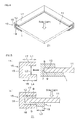
- FIG. 4 shows a partially cross-sectional perspective view of a solar cell module using the sealing member for solar cell panel shown in FIG. 1 .
- FIG. 5 shows a process step view for illustrating the assembly of the solar cell module shown in FIG. 4 , (a) showing the step of sticking the sealing member for solar cell panel to a peripheral end portion of the solar cell panel, and (b) showing the step of fixing the peripheral end portion of the solar cell panel.
- the solar cell module 21 includes a solar cell panel 11, the sealing member 1, and a frame 15 as a fixing member.
- the solar cell panel 11 has a generally rectangular flat-plate shape, and a known solar cell panel such as a thin-film type is used.
- the thin-film-type solar cell panel 11 comprises a power generation layer, a glass substrate (not shown) formed on a light receiving surface 8 which receives solar light of the power generation layer, a resin layer (not shown), and a protective layer (not shown) which are successively formed on a back surface (surface opposite to the light receiving surface) 9 of the power generation layer.
- a terminal cable not shown
- a terminal box for containing the terminal cable, though not shown.
- the thickness of the solar cell panel 11 is in a range of, e.g., 2 to 10 mm, or preferably 4 to 6 nm.
- the sealing member 1 is formed in a sheet or film shape extending in a longitudinal direction to seal a peripheral end portion 12 of the solar cell panel 11. More specifically, as shown in FIG. 5(a) , the sealing member 1 is formed in a generally U-shaped cross-sectional shape in contact relation with a side surface 7, the light receiving surface 8, and the back surface 9 at the peripheral end portion 12 of each of the sides of the solar cell panel 11.
- the sealing member 1 is sticked to the peripheral end portion 12 of the solar cell panel 11 so as to bring the first water-stopping self-adhesive layer 4 thereof into contact with each of the surfaces of the peripheral end portion 12.
- the sealing member 1 disposed on the back surface 9 is formed longer than the sealing member 1 disposed on the light receiving surface 8 in a direction extending inwardly from the peripheral end portion 12 of the solar cell panel 11. More specifically, the sealing member 1 disposed on the back surface 9 is formed longer than the sealing member 1 disposed on the light receiving surface 8 by, e.g., 1 to 30 mm, or preferably 10 to 20 mm. As shown in FIGS. 4 and 5 , the frame 15 is provided along each of the sides of the solar cell panel 11.
- the frame 15 is formed in a generally U-shaped cross-sectional shape which inwardly opens, and integrally includes a side-surface sidewall 16 having a flat-plate shape, a light-receiving-surface sidewall 17 having a flat-plate shape, and extending inwardly from an upper portion of the side-surface sidewall 16, and a back-surface sidewall 18 having a flat-plate shape, and extending inwardly from a lower portion of the side-surface sidewall 16.
- the frame 15 is formed of, e.g., a metal material (such as aluminum) or a resin material, or preferably formed of aluminum.
- the frame 15 has longitudinal end portions along the individual sides thereof which are joined to each other to form four corners, and assembled in a frame shape when viewed in plan view.
- the dimensions of the frame 15 are set appropriately based on the dimensions of the solar cell panel 11 and the sealing member 1.
- the length L1 of the inner surface of the light-receiving-surface sidewall 17 is in a range of, e.g., 5 to 30 mm, or preferably 10 to 20 mm.
- the length L4 of the inner surface of the back-surface sidewall 18 is in a range of, e.g., 5 to 50 mm, or preferably 15 to 25 mm.
- the length L2 of the inner surface of the side-surface sidewall 16 is in a range of, e.g., 5 to 15 mm, or preferably 8 to 10 mm.
- the respective thicknesses of the peripheral-surface sidewall 16, the light-receiving-surface sidewall 17, and the back-surface sidewall 18 are in a range of, e.g., 1 to 5 mm, or preferably 2 to 4 mm.
- the frame 15 further engagedly holds the sealing member 1 engagedly holding the peripheral end portion 12 of the solar cell panel 11.
- the light-receiving-surface sidewall 17 covers the sealing member 1 disposed on the light receiving surface 8
- the side-surface sidewall 16 covers the sealing member 1 disposed on the side surface 7
- the back-surface sidewall 18 covers the sealing member 1 disposed on the back surface 9.
- the inner end portion of the sealing member 1 disposed on the back surface 9 is exposed from the back-surface sidewall 18 of the frame 15.
- the length L3 of the exposed portion 19 is in a range of, e.g., 1 to 30 mm, or preferably 10 to 20 mm.
- the inner end portion of the sealing member 1 disposed on the light receiving surface 8 is disposed not flush with, but rather slightly closer to the peripheral-end side than the inner end portion of the light-receiving-surface sidewall 17 of the frame 15 in the inward direction.
- the inner end portion of the sealing member 1 disposed on the light receiving surface 8 is disposed closer to the peripheral-end side by, e.g., 1 to 3 mm.
- the peripheral end portion 12 of the solar cell module 11 sealed with the sealing member 1 is press-fitted into the frame 15, as indicated by the arrow of FIG. 5(a) , and shown in FIG. 5(b) . More specifically, the peripheral end portion 12 of the solar cell panel 11 is inserted into the frame 15 so as to be engagedly held by the frame 15 via the sealing member 1. Accordingly, the sealing member 1 is engagedly held by the frame 15, and the peripheral portion 12 of the solar cell module 11 is fixed in the frame 15 via the sealing member 1.
- the sealing member 1 By causing the frame 15 to engagedly hold the sealing member 1, the sealing member 1 is compressed to a volume at a ratio in a range of 10 to 90 vol%, or preferably 20 to 80 vol% with respect to the volume before the sealing member 1 is engagedly held. As a result, the solar cell panel 11 is sealed with the sealing member 1, and the sealing member 1 is engagedly held by the frame 15 to allow the assembly of the solar cell module 21 fixed by the frame 15.
- the elastic layer 2 functions as a shock absorbing layer. Therefore, it is possible to ensure excellent fixation of the solar cell panel 11 to the frame 15. Since the insulating resin film 3 has excellent voltage resistance, it is possible to impart excellent voltage resistance to the solar cell module 21, and obtain the solar cell module 21 having excellent durability. Moreover, since the first water-stopping self-adhesive layer 4 has excellent water resistance, it is possible to impart excellent water resistance to the solar cell module 21, and prevent a reduction in power generation efficiency due to the entrance of water.
- the sealing member 1 disposed on the back surface 9 is formed longer than the sealing member 1 disposed on the light-receiving surface 8 in the direction inwardly extending from the peripheral end portion 12 of the solar cell panel 11.
- the sealing member 1 disposed on the back surface 9 is formed longer than the sealing member 1 disposed on the light receiving surface 8 in the direction inwardly extending from the peripheral end portion 12 of the solar cell panel 11. This more positively ensures insulation between the frame 15 and the solar cell panel 11, and can prevent discharge between the frame 15 and the solar cell panel 11 even at the time of unexpected momentary occurrence of a voltage, such as a lightning surge.
- EPDM EPT4021 commercially available from Mitsui Chemical, Inc.
- ADCA 5 parts of an urea-type foaming auxiliary
- 100 parts of ethylene-bis-pentabromodiphenyl 50 parts of aluminum hydroxide, 50 parts of magnesium hydroxide, 10 parts of carbon black, 1.5 parts of sulfur, 5 parts of zinc oxide, 1.2 parts of dithiocarbamic acid salts (vulcanization accelerator), 1.0 part of thiazoles (vulcanization accelerator), 3 parts of stearic acid powder, 35 parts of a process oil, and 1 part of low molecular polyethylene glycol were kneaded with a pressure kneader to prepare a foaming composition.
- EPDM EPT4021 commercially available from Mitsui Chemical, Inc.
- ADCA 5 parts of an urea-type foaming auxiliary
- 100 parts of ethylene-bis-pentabromodiphenyl 50 parts of aluminum hydroxide, 50 parts of magnesium hydroxide, 10 parts of carbon black, 1.5 parts
- an unvulcanized sheet having a thickness of 10 mm was obtained, and then heated in an oven at 160 °C for 20 minutes to be vulcanized and foamed. In this manner, an elastic layer made of an EPDM foam was produced.
- a tackifier (petroleum-derived resin "Escorez 1202" commercially available from Exxon Mobil Corporation) was loaded and kneaded for about 10 minutes, and 100 g of a softener A ("Polybutene HV300" commercially available from Nippon Petrochemicals Co., Ltd.) and 300 g of a softener B ("Process Oil PW90" having a weight average molecular weight of 500, and commercially available from Idemitsu Kosan Co., Ltd.) were further kneaded in several separate steps for about 10 minutes. Thereafter, a kneaded material was collected from the kneader to prepare a rubber-type self-adhesive.
- a tackifier petroleum-derived resin "Escorez 1202" commercially available from Exxon Mobil Corporation
- an insulating resin film made of PET, and having a thickness of 25 ⁇ m was prepared, and a fibrous sheet made of woven fabric was sticked to the surface of the insulating resin film via an adhesive.
- the insulating resin film with the fibrous sheet was set on a calendar roll, and a first water-stopping self-adhesive layer made of the rubber-type self-adhesive was laminated on the back surface of the insulating resin film.
- a second water-stopping self-adhesive layer made of the same rubber-type self-adhesive as described above was laminated (see FIG. 1 ).
- a sealing member for solar cell panel having a thickness of 3.0 mm was produced in which the second water-stopping self-adhesive layer, the fibrous sheet, the insulating resin film, and the first water-stopping self-adhesive layer were successively laminated on the elastic layer.
- the sealing member for solar cell panel produced as described above was sticked to the peripheral end portion of a solar cell panel (thin-film solar cell panel having a thickness of 5 mm) such that the first water-stopping self-adhesive layer in a generally U-shaped shape came in contact with the peripheral end portion of the solar cell panel (see FIG. 5(a) ).
- a frame made of aluminum, having a U-shaped cross-sectional shape, and including a back-surface sidewall, a peripheral-surface sidewall, and a light-receiving-surface sidewall was prepared.
- the length of the inner surface of the light-receiving-surface sidewall was 10 mm
- the length of the inner surface of the back-surface sidewall was 11 mm
- the length of the inner surface of the side-surface sidewall was 7 mm.
- the thickness of each of the walls was 2.0 mm.
- the engagedly held sealing member was compressed to a volume at a ratio of 33 vol% with respect the volume before the sealing member was engagedly held. That is, the thickness of the sealing member was reduced from 3.0 mm to 1.0 mm. Note that the sealing member sticked to the back surface was formed longer by about 2.5 mm than the sealing member sticked to the light receiving surface. The inner end portion of the sealing member on the back surface was exposed from the inner end portion of the back-surface sidewall of the frame, and the length of the exposed portion was about 10 mm.
- the inner end portion of the sealing member on the light receiving surface was covered with the light-receiving-surface sidewall of the frame. Specifically, the inner end portion of the sealing member sticked to the light receiving surface was disposed closer by about 1.5 mm to the peripheral-end side than the inner end portion of the light-receiving-surface sidewall of the frame in the inward direction.
- a sealing member for solar cell panel was produced in the same manner as in EXAMPLE 1 except that, in the production of the sealing member for solar cell panel, the thickness of the insulating resin film was changed from 25 ⁇ m to 18 ⁇ m. Subsequently, a solar cell module was produced.
- a sealing member for solar cell panel was produced in the same manner as in EXAMPLE 1 except that, in the production of the sealing member for solar cell panel, the thickness of the insulating resin film was changed from 25 ⁇ m to 50 ⁇ m. Subsequently, a solar cell module was produced.
- a solar cell module was produced in the same manner as in EXAMPLE 1 except that the length of the sealing member for solar cell panel sticked to the back surface of the solar cell panel was adjusted to be the same as the length of the sealing member for solar cell panel sticked to the light receiving surface of the solar cell panel (see the broken line of FIG. 5(b) ).
- the inner end portion of the sealing member sticked to the light receiving surface was disposed closer by about 1.5 mm to the peripheral-end side than the inner end portion of the light-receiving-surface sidewall of the frame in the inward direction.
- the inner end portion of the sealing member sticked to the back surface was disposed closer by about 2.5 mm to the peripheral-end side than the inner end portion of the back-surface sidewall of the frame in the inward direction.
- a sealing member for solar cell panel was produced in the same manner as in EXAMPLE 1 except that, in the production of the sealing member for solar cell panel, spun rayon fabric having a thickness of 0.2 mm was used instead of the insulating resin film. Subsequently, a solar cell module was produced.
- an impulse voltage of 8 kV (under the conditions of application class A, and a maximum system voltage of 1000 V according to the IEC standard 61730) was applied between the frame and the solar cell panel under room temperature conditions (at a temperature of 25 °C and a relative humidity of 25%).
- Each of the solar cell modules obtained in EXAMPLES 1 to 4 and COMPARATIVE EXAMPLE 1 was placed perpendicularly to a wall surface, and the surface of the solar cell module was sprinkled with water (4 L/minute) so that the water-stopping test was evaluated.
- the sealing member for solar cell panel of the present invention can be used for the waterproofing of a solar cell module or the like.
Landscapes
- Photovoltaic Devices (AREA)
- Laminated Bodies (AREA)
- Sealing Material Composition (AREA)
- Compositions Of Macromolecular Compounds (AREA)
Abstract
[Abstract] Disclosed is a sealing member for solar cell panels, which comprises an elastic layer, an insulating resin film arranged on the elastic layer, and a first water-stopping adhesive layer arranged on the insulating resin film.
Description
- The present invention relates to a sealing member for solar cell panel and a solar cell module, and particularly to a sealing member for solar cell panel and a solar cell module in which it is used.
- Conventionally, solar cell panels have been used mainly outdoors. In such usage, a solar cell panel is fixed to a frame fixing member or the like.
As the solar cell panel, there has been known a thin-film solar cell panel in which a power generation layer including a transparent electrode layer, a photoelectric conversion layer, and a metal electrode layer is interposed between a glass substrate and a resin layer. In this thin-film solar cell panel, the power generation layer is generally formed at a peripheral end portion. Accordingly, when water enters a space between the fixing member and the peripheral end portion of the solar cell panel, water enters the power generation layer, and the photoelectric conversion layer peels off the transparent electrode layer and the metal electrode layer, which causes the problem of a reduction in power generation efficiency. Therefore, it is necessary to waterproof the peripheral end portion of the thin-film solar cell panel. - For this purpose, it is proposed to, e.g., fix the peripheral end portion of the solar cell panel in a groove having a generally U-shaped cross-sectional shape of a frame member via a gasket (sealing member) to seal (waterproof) the peripheral end portion of the solar cell panel (see, e.g.,
Patent Document 1 shown below).
In addition, as a general-purpose sealing member, there is proposed, e.g., a foam of ethylene-propylene-type rubber (see, e.g., Patent Document 2 shown below). - Patent Document 1: Japanese Unexamined Patent No.
2005-277260 - Patent Document 2: Japanese Unexamined Patent No.
2001-131320 - In recent years, a thin-film solar cell panel used outdoors has been intended to be scaled up. Since a high voltage is placed on such a thin-film solar cell panel, excellent voltage resistance is required of a sealing member.
However, when only the foam of ethylene-propylene-type rubber is used as the sealing member, the voltage resistance is insufficient. In the thin-film solar cell panel using the sealing member, it may be impossible to prevent a problem such as damage due to the high voltage. - An object of the present invention is to provide a sealing member for solar cell panel having excellent water resistance and voltage resistance, and a solar cell module in which it is used.
- To attain the object, a sealing member for solar cell panel of the present invention includes an elastic layer, an insulating resin film laminated on the elastic layer, and a first water-stopping self-adhesive layer laminated on the insulating resin film.
In the sealing member for solar cell panel of the present invention, it is preferable that the insulating resin film is made of polyethylene terephthalate. - In the sealing member for solar cell panel of the present invention, it is preferable that the first water-stopping self-adhesive layer is made of butyl rubber.
In the sealing member for solar cell panel of the present invention, it is preferable that the sealing member for solar cell panel of the present invention further includes a second water-stopping self-adhesive layer interposed between the elastic layer and the insulating resin film.
In the sealing member for solar cell panel of the present invention, it is preferable that the second water-stopping self-adhesive layer is made of butyl rubber. - In the sealing member for solar cell panel of the present invention, it is preferable that the elastic layer is made of ethylene-propylene-diene rubber.
In the sealing member for solar cell panel of the present invention, it is preferable that the elastic layer is formed of a foam.
In the sealing member for solar cell panel of the present invention, it is preferable that the elastic layer is formed of a foam of ethylene-propylene-diene rubber. - A solar cell module of the present invention includes a solar cell panel, the above-mentioned sealing member for solar cell panel which seals a peripheral end portion of the solar cell panel, and a fixing member engagedly holding the sealing member for solar cell panel.
In the solar cell module of the present invention, it is preferable that the sealing member for solar cell panel is disposed so as to come in contact with a side surface of the solar cell panel, a light-receiving surface thereof, and a back surface thereof opposite to the light-receiving surface at the peripheral end portion of the solar cell panel, and the sealing member for solar cell panel disposed on the back surface is formed longer than the sealing member for solar cell panel disposed on the light-receiving surface in a direction extending inwardly from the peripheral end portion of the solar cell panel. - The sealing member for solar cell panel of the preset invention includes the elastic layer, the insulating resin film, and the first water-stopping self-adhesive layer. Since the elastic layer functions as a shock absorbing layer, it is possible to ensure satisfactory fixation of the solar cell panel to the fixing member.
In addition, since the insulating resin film has excellent voltage resistance, it is possible to impart excellent voltage resistance to the solar cell module, and obtain the solar cell module having excellent durability. - Furthermore, since the first water-stopping self-adhesive layer has excellent water resistance, it is possible to impart excellent water resistance to the solar cell module, and prevent a reduction in power generation efficiency due to the entrance of water.
Since the power cell module of the present invention uses the sealing member for power cell panel described above, it is possible to ensure excellent voltage resistance and excellent water resistance. -
- [
FIG. 1] FIG. 1 shows an enlarged cross-sectional view of an embodiment of a sealing member for solar cell panel of the present invention. - [
FIG. 2] FIG. 2 shows an enlarged cross-sectional view of another embodiment of the sealing member for solar cell panel of the present invention. - [
FIG. 3] FIG. 3 shows an enlarged cross-sectional view of still another embodiment of the sealing member for solar cell panel of the present invention. - [
FIG. 4] FIG. 4 shows a partially cross-sectional perspective view of a solar cell module using the sealing member for solar cell panel shown inFIG. 1 . - [
FIG. 5] FIG. 5 shows a process step view for illustrating the assembly of the solar cell module shown inFIG. 4 ,- (a) showing the step of sticking the sealing member for solar cell panel to a peripheral end portion of the solar cell panel, and
- (b) showing the step of fixing the peripheral end portion of the solar cell panel.
-
FIG. 1 shows an enlarged cross-sectional view of an embodiment of a sealing member for solar cell panel of the present invention.
Referring toFIG. 1 , the sealing member for solar cell panel of the present invention (which may be hereinafter simply referred to also as "sealing member") is described hereinbelow.
InFIG. 1 , the sealingmember 1 is formed into a sheet-like or film-like shape, and includes an elastic layer 2, a second water-stopping self-adhesive layer 5 laminated on the elastic layer 2, afibrous sheet 6 laminated on the second water-stopping selfadhesive layer 5, an insulating resin film 3 laminated on thefibrous sheet 6, and a first water-stopping self-adhesive layer 4 laminated on the insulating resin film 3. - The elastic layer 2 is not particularly limited as long as it has a shock absorbing (cushioning) function. For example, the elastic layer 2 is formed of a molded piece of various rubber.
Examples of a material forming the elastic layer 2 that can be used include such as, e.g., ethylene-propylene-diene rubber (EPDM); a-olefin dicyclopentadiene such as, e.g., 1-butene;rubber-type copolymers containing, as a component, cyclic or non-cyclic polyene having a non-conjugated double bond such as, e.g., ethylidene norbornene; various rubbers such as e.g., ethylene-propylene rubber, ethylene-propylene terpolymer, silicone rubber, polyurethane-type rubber, polyamide-type rubber, natural rubber, polyisobutylene rubber, polyisoprene, chloroprene rubber, butyl rubber, nitrile-butyl rubber, styrene-butadiene rubber, styrene-butadiene-styrene rubber, styrene-isoprene-styrene rubber, styrene-ethylene-butadiene rubber, styrene-ethylene-butylene-styrene rubber, styrene-isoprene-propylene-styrene rubber, and acrylic rubber. Preferably, in terms of weathering resistance, EPDM can be used. - Examples of diene forming EPDM that can be used include cyclic dienes such as, e.g., 5-ethylidene-2-norbornene, 5-propylidene-5-norbornene, dicyclopentadiene, 5-vinyl-2-norbornene, 5-methylene-2-norbornene, 5-isopropylidene-2-norboronen, and norbornadiene,; chain non-conjugated dienes such as, e.g., 1,4-hexadiene, 4-methyl-1,4-hexaadiene, 5-methl-1,4-hexadiene, 5-methyl-1,5-heptadiene, 6-methyl-1,5-heptadiene, 6-methyl-1,7-octadiene, and 7-methyl-1,6-octadiene, and trienes such as, e.g., 2,3-diisopropylidene-5-norbornene, and 4-ethylidene-8-methyl-1,7-nonadiene.
- Among such dienes, a diene that allows a reduction in diene content, and has a high vulcanization speed can be preferably used in terms of allowing the obtention of an EPDM foam having excellent heat resistance and weathering resistance. More specifically, 5-ethylidne-2-norbornen can be used.
The Mooney viscosity of EPDM is in a range of, e.g., 10 to 60 (ML1+4, 100 °C), or preferably 20 to 50 (ML1+4, 100 °C). When the Mooney viscosity is within the range shown above, an advantage is offered that a soft EPDM foam having excellent workability and softness can be obtained. - The diene content of EPDM expressed as an iodine value is in a range of, e.g., 0.5 to 50 (g/100 g), or preferably 10 to 30 (g/100 g). When the diene content is within the range shown above, excellent heat resistance and weathering resistance can be obtained. The ethylene content is in a range of, e.g., 50 to 75 wt%, or preferably 50 to 55 wt%. When the ethylene content is within the range shown above, an advantage is offered that permanent compression set at a low temperature is reduced.
- EPDM can be used alone, or two or more different types thereof having different physical properties can be used in combination.
In the sealingmember 1, the elastic layer 2 is preferably formed of a foam, or more preferably formed of an EPDM foam.
The foam can be obtained by heating a foaming composition containing any of the various rubbers described above, a foaming agent, a crosslinking agent, and an additive to cause foaming or crosslinkage thereof. - Examples of the foaming agent that can be used include thermolytic foaming agents such as an inorganic foaming agent and an organic foaming agent.
Examples of the inorganic foaming agent that can be used include ammonium carbonate, ammonium hydrogen carbonate, sodium hydrogen carbonate, ammonium nitrite, sodium borohydride, and azides.
Examples of the organic foaming agent that can be used include an N-nitroso-type compound (such as, e.g., N,N'-dinitrosopentamethylenetetramine or N,N'-dimethyl- N,N'-dinitrosoterephthalamide), an azo-type compound (such as, e.g., azobisisobutylonitrile, azodicarboxylic acid amide (ADCA), or barium azodicarboxylate), alkane fluoride (such as, e.g., trichloromonofluoromethane or dichloromonofluoromethane), a hydrazine-type compound (such as, e.g., paratoluenesulfonyl hydrazide, diphenylsulfone-3,3'-disulfonyl hydrazide, 4,4'-oxybis(benzenesulfonyl hydrazide) (OBSH), or allylbis(sulfonylhydrazide)), a semicarbazide-type compound (such as, e.g., p-toluylenesulfonylsemicarbazide or 4,4'-oxybis(benzenesulfonylsemicarbazide), and a triazole-type compound (such as, e.g., 5-morphoryl-1,2,3,4-thiatriazole). - Examples of the foaming agent that can be used also include a gas-filled microcapsule foaming agent. More specifically, there can be used a thermoexpansive particulate in which a thermoexpansive substance (such as, e.g., isobutane or pentane) is encapsulated in a microcapsule (microcapsule made of a thermoplastic resin such as, e.g., vinylidene chloride, acrylonitrile, acrylic acid ester, or methaclylic acid ester) or the like. As such a thermoexpansive particulate, a commercially available product such as, e.g., Microsphere (product name, commercially available from Matsumoto Yushi-Seiyaku Co., Ltd.).
- Of such foaming agents, one can be used alone, or two or more can be used in combination. Among such foaming agents, ADCA can be preferably used.
The mixing ratio of the foaming agent based on 100 parts by weight of the rubber is in a range of, e.g., 0.1 to 100 parts by weight, or preferably 0.5 to 50 parts by weight.
The crosslinking agent is usually a vulcanizing agent. Examples of such a vulcanizing agent that can be used include sulfur, sulfur compounds, selenium, magnesium oxides, a lead monoxide, zinc oxides, organic peroxides, polyamines, oximes (such as, e.g., p-quinone dioxime or p,p'-dibenzoylquinone dioxime), nitroso compounds (such as, e.g., p-dinitrosobenzine), resins (such as, e.g., alkylphenol-formaldehyde resins or melamine-formaldehyde condensates), and ammonium salts (such as, e.g., ammoniumbenzoate). - Among such crosslinking agents, sulfur or sulfur compounds can be preferably used in terms of the vulcanization property of the foam, the physical property thereof such as durability due to a foaming property, and the like. More preferably, sulfur can be used.
Of such vulcanizing agents, one can be used alone, or two or more can be used in combination.
The mixing ratio of the vulcanizing agent can be determined appropriately in accordance with crosslinking (vulcanization) efficiency based on the type thereof. When the vulcanizing agent is sulfur or a sulfur compound, the mixing ratio thereof based on 100 parts by weight of the rubber is preferably in a range of, e.g., 0.1 to 10 parts by weight, or preferably 0.5 to 5 parts by weight. - Examples of the additive that can be used include a flame retardant, a vulcanization accelerator, a softener, a filler, and a foaming auxiliary.
The flame retardant is mixed when flame retardancy is required of the elastic layer 2. Examples of such a flame retardant that can be used include metal hydroxides of metal elements such as aluminum (Al), magnesium (Mg), calcium (Ca), nickel (Ni), cobalt (Co), tin (Sn), zinc (Zn), copper (Cu), iron (Fe), titanium (Ti), and boron (B). Among these metal hydroxides, aluminum hydroxide or magnesium hydroxide can be preferably used. - As the flame retardant, there can be also used, e.g., a complex metal hydroxide which is a metal hydroxide including two or more metal elements. Examples of such a complex metal hydroxide that can be used include sMgO·(1-s)NiO·cH2O (0<s<1, 0<c≤19), sMgO·(1-s)ZnO·cH2O (0<s<1, 0<c≤1), and sAl2O3·(1-s)Fe2O3·cH2O 0<s<1, 0<c≤3).
- Among such complex metal hydroxides, a complex metal hydroxide including magnesium and nickel or zinc can be used. More specifically, a complex metal hydroxide represented by sMgO·(1-s)Q10·cH20 (where Q1 represents Ni or Zn, and 0<s<1 and 0<c≤1 are satisfied) can be used. More preferably, hydrates of magnesium oxide and nickel oxide, and hydrates of magnesium oxide and zinc oxide can be used.
- The complex metal hydroxide may have a polygonal shape or a thin- plate shape. When the complex metal hydroxide having a polygonal shape is used, a highly foamed foam can be obtained.
The mean diameter of particles (mean particle diameter) of the metal hydroxide or the complex metal hydroxide is in a range of, e.g., about 0.5 to 10 µm, or preferably 0.6 to 6 µm. The mean particle diameter can be measured with, e.g., a laser-type particle size measuring device. When the mean particle diameter exceeds 10 µm, a highly foamed foam may not be easily obtained. - As the flame retardant, there can be also used a bromine-type compound. Examples of such a bromine-type compound that can be used include an imide-type bromine compound such as, e.g., ethylene-bis-tetra-bromophthalimide; a phthalic-acid-type bromine compound such as, e.g., tetrabromophthalic acid anhydride; a bisphenol-type bromine compound such as, e.g., tetrabromobisphenol A and tetrabromobisphenol S; a biphenyl-type bromine compound such as, e.g., hexabromobiphenyl ether, decabromodiphenyl oxide, octabromodiphenyl oxide, and tetrabromodiphenyl oxide; an aliphatic bromine compound such as, e.g., ethylene-bis-pentabromodiphenyl and 1,2-bis-tetrabromophenylethane; an alicyclic bromine compound such as, e.g., hexabromocyclododecane; an aromatic bromine compound such as, e.g., bis(tribromophenoxy)ethane, bis(pentabromophenyl)ethane, tetrabromobenzene, pentabromobenzene, hexabromobenzene, tris(2,3-dibromopropyl-1)isocyanurate, and brominated polyphenylene ether; a phenol-type bromine compound such as, e.g., tribromophenol; a styrene-type bromine compound such as, e.g., brominated polystyrene; an acrylic-type bromine compound such as, e.g., brominated polyacrylate; an epoxy-type bromine compound such as brominated-bisphenol-A-type epoxy resin or a modified product thereof, and a carboxylic-acid-type bromine compound.
- Among such bromine-type compounds, bromine-type compounds other than decabromodiphenyl oxide are preferred.
When the flame retardant is a metal hydroxide or a complex metal hydroxide, the mixing ratio of the flame retardant based on 100 parts by weight of the rubber is in a range of, e.g., 30 to 200 parts by weight, preferably 40 to 180 parts by weight, or more preferably 50 to 150 parts by weight. - When the flame retardant is a bromine-type compound, the mixing ratio of the flame retardant with respect to the foaming composition is in a range of, e.g., 4 to 25 wt%, or preferably 10 to 15 wt%. When the mixing ratio of the bromine-type compound is under the range shown above, the flame retardant effect may be reduced and, when the flame retardant is used in combination with the complex metal hydroxide (complex metal hydroxide having a polygonal shape), the mixing ratio of the complex metal hydroxide may not be able to be reduced. On the other hand, when the mixing ratio of the bromine-type compound exceeds the range shown above, a highly foamed foam may not be able to be obtained.
- The vulcanization accelerator is added to adjust a vulcanization property, or accelerate vulcanization. Examples of the vulcanization accelerator that can be used include guanidines, thiazoles, sulfene amides, thiurams, dithiocarbamic acids, xanthic acids, aldehyde ammonias, aldehyde amines, and thioureas.
The mixing ratio of the vulcanization accelerator based on 100 parts by weight of the rubber is in a range of, e.g., 0.1 to 10 parts by weight. - The softener is added to improve moldability or workability. Examples of the softener that can be used include e.g., paraffins, waxes, naphtenes, aromatic oils, asphalts, drying oils such as, flaxseed oils, animal/vegetable oils, petroleum-derived oils (such as, e.g., process oils), various low-molecular polymers (such as, e.g., low-molecular polyethylene glycol), phthalic acid esters, phosphoric acid esters, stearic acid or esters thereof, alkyl sulfonic acid esters, and tackifiers.
- The mixing ratio of the softener is determined appropriately based on the physical properties of the elastic layer 2 or the like. For example, in terms of rubber physical properties, low toxicity, a low density property, miscibility, and the like, the mixing ratio of the softener based on 100 parts by weight of the rubber is in a range of, e.g., 10 to 100 parts by weight, preferably 15 to 80 parts by weight, or more preferably 20 to 60 parts by weight.
The filler is added to adjust the strength of the foam. Examples of the filler that can be used include carbon black. The filler is mixed at an appropriate ratio. - Examples of the foaming auxiliary that can be used include urea-type foaming auxiliaries. The foaming auxiliary is mixed at an appropriate ratio.
Of such additives, one can be used alone, or two or more can be used in combination.
To prepare the foaming composition, the individual components mentioned above are mixed at the foregoing mixing ratios, and uniformly mixed with each other. To mix the individual components mentioned above, the components mentioned above are kneaded with, e.g., a mixing roll, a pressure kneader, an extruder, or the like. Note that the components mentioned above are mixed at a temperature lower than a temperature at which the foaming agent causes foaming, and the foaming agent (vulcanizing agent) causes crosslinkage (vulcanization) (e.g., at a temperature in a range lower than 160 °C, or preferably 40 to 100 °C). The obtained foaming composition is molded into a sheet-like shape by a molding method such as, e.g., mixing roll, calendar roll, extrusion molding, press molding, or the like. - Then, the foaming composition mentioned above is heated at a temperature in a range of not more than 450 °C, or preferably 100 to 350 °C, whereby the foam is obtainable.
The foam thus obtained has a density (Weight of Foam (g)/Volume of Foam (g/cm3)) thereof in a range of, e.g., 0.01 to 0.5 g/cm3, and the expansion ratio (volume expansion ratio) thereof during the foaming is in a range of, e.g., 1.1 to 25 times or more, or preferably 1.5 to 20 times. - The thickness of the elastic layer 2 is in a range of, e.g., 0.5 to 30 mm, or preferably 1 to 10 mm.
The first water-stopping self-adhesive layer 4 is not particularly limited as long as it has a watertight function. Examples of a self-adhesive (first self-adhesive) forming the first water-stopping self-adhesive layer 4 that can be used include a rubber-type self-adhesive and a resin-type self-adhesive. Preferably, a rubber-type self-adhesive can be used.
In the rubber-type self-adhesive, an additive has been uniformly dispersed in rubber. Examples of the rubber that can be used include butyl rubber and rubber asphalt. In terms of durability and weathering resistance, butyl rubber can be preferably used. More preferably, reclaimed butyl rubber having excellent workability can be used. - In addition, synthetic rubber such as butadiene rubber, isoprene rubber, or polyisobutylene can also be used in combination.
Examples of the adder that can be used include a filler such as, e.g., calcium carbonate; a tackifier such as, e.g., a petroleum-derived resin, a phenol-type resin, a rosin-type resin, a terpene-type resin, or a hydrogenerated product thereof, and a softener such as, e.g., process oil or polybutene. - Of such additives, one can be used alone, or two or more can be used in combination. The mixing ratio of the additive based on 100 parts by weight of the rubber is such that the mixing ratio of the filler is in a range of, e.g., not more than 200 parts by weight, the mixing ratio of the tackifier is in a range of, e.g., 20 to 200 parts by weight, and the mixing ratio of the softener is in a range of, e.g., 5 to 150 parts by weight.
In the rubber-type self-adhesive, a crosslinking agent may also becontained in addition to the additives mentioned above.
The crosslinking agent is arbitrarily mixed in the rubber-type self-adhesive. There can be used a crosslinking agent which enables crosslinkage at a low temperature (of, e.g., not more than 180 °C), and causes crosslinkage at a relatively high speed. Examples of the cross-linking agent that can be used include a quinoide vulcanizing agent, a thiuram vulcanizing agent, a quinonedioxime vulcanizing agent, and a maleimide vulcanizing agent. - Examples of the quinoide vulcanizing agent that can be used include poly-p-dinitrosobenzene. Examples of the thiuram vulcanizing agent that can be used include tetramethylthiuramdisulfide, tetraethylthiuramdisulfide, tetrabutylthiuramdisulfide, tetrakis(2-ethylhexyl)thiuramdisulfide, dipentamethylenethiuramtetrasulfide, and tetramethylthiurammonosulfide. Examples of the quinonedioxime vulcanizing agent that can be used include p-quinondioxime and p,p'-dibenzoylquinonedioxime. Examples of the maleimide vulcanizing agent that can beused include N,N'-m-phenylenedimaleimide, N,N'-p-phenylenedimaleimide, and N,N'-ethylenedimaleimide.
- Of such cross-linking agents, one can be used alone, or two or more can be used in combination.
The mixing ratio of the crosslinking agent based on 100 parts by weight of the rubber is in a range of, e.g., not more than 20 parts by weight, or preferably 0.5 to 20 parts by weight.
By mixing the crosslinking agent in the rubber-type self-adhesive, the rubber-type self-adhesive can be prepared as a rubber-type self-adhesive of a crosslinking type. - To form the first water-stopping self-adhesive layer 4, the first self-adhesive is prepared first.
To prepare the first self-adhesive, the individual components mentioned above are mixed at the foregoing mixing ratios, heated, and kneaded. For the kneading, there is used, e.g., a batch kneader such a pressure kneader, a Banbury mixer, or a mixing roll, a continuous kneader such as a double-shaft kneader, or the like. A heating temperature in the kneading is in a range of, e.g., 40 to 160 °C, or preferably 40 to 100 °C. - Then, the first self-adhesive is heated, and molded with a molding device such as, e.g., a calendar roll or an extruder, or preferably the calendar roll, whereby the first water-stopping self-adhesive layer 4 is obtainable.
The thickness (thickness of the paste) of the first water-stopping self-adhesive layer 4 thus obtained is in a range of, e.g., 10 to 1000 µm, or preferably 100 to 500 µm. - The
fibrous sheet 6 is used to reinforce and support the insulating resin film 3 during the production. Examples of thefibrous sheet 6 that can be used include woven or non-woven fabric of cotton, spun rayon, synthetic fiber, or the like, and paper such as, e.g., Japanese paper or kraft paper. Preferably, woven fabric can be used.
Thefibrous sheet 6 can be used alone, or two or more types thereof can be used in combination. The thickness of thefibrous sheet 6 is in a range of, e.g., 1 to 100 µm, or preferably 10 to 50 µm. - The insulating resin film 3 is not particularly limited as long as it is a film having an insulating function. Examples of an insulating resin forming the insulating resin film that can be used include synthetic resins such as polyethylene terephthalate (PET), polyimide, polyether nitrile, polyether sulfone, polyethylene naphthalate, and polyvinyl chloride. Preferably, PET can be used. Note that a woven or porous insulating resin film is not preferred because the insulating property thereof significantly deteriorates.
- The thickness of the insulating resin film 3 is in a range of, e.g., not more than 100 µm, or preferably 1 to 80 µm.
The second water-stopping self-adhesive layer 5 is not particularly limited as long as it has a watertight function. For example, the second water-stopping self-adhesive layer 5 can be formed of a self-adhesive (second self-adhesive). Preferably, the second self-adhesive is formed of the same self-adhesive as the first self-adhesive. More preferably, the second self-adhesive is formed of butyl rubber. The second water-stopping self-adhesive layer 5 is formed by the same method as used to form the first water-stopping self-adhesive layer 4. The thickness of the second water-stopping self-adhesive layer 5 is the same as that of the first water-stopping self-adhesive layer 4. - Next, a description is given to a producing method of the sealing
member 1.
First, in this method, thefibrous sheet 6 is laminated on the surface of the insulating resin film 3. To laminate thefibrous sheet 6, thefibrous sheet 6 is sticked to the surface of the insulating resin film 3 via a known adhesive. Note that, in the lamination of thefibrous sheet 6, thefibrous sheet 6 can also be laminated on the surface of the insulating resin film 3 by thermocompression. Next, the first water-stopping self-adhesive layer 4 is laminated on the back surface (surface opposite to the surface thereof on which thefibrous sheet 6 is laminated) of the insulating resin film 3. To laminate the first water-stopping self-adhesive layer 4, the first water-stopping self-adhesive layer 4 is molded into a sheet shape on the back surface of the insulating resin film 3 with the molding device mentioned above (preferably a calendar roll). - Next, the second water-stopping self-
adhesive layer 5 is laminated on the surface of thefibrous sheet 6. To laminate the second water-stopping self-adhesive layer 5, the second water-stopping self-adhesive layer 5 is molded into a sheet shape with the molding device mentioned above (preferably a calendar roll) on the top surface of thefibrous sheet 6.
In this manner, the insulating resin film 3 can be obtained which has the first water-stopping self-adhesive layer 4 laminated on the back surface thereof, and has thefibrous sheet 6 and the second water-stopping self-adhesive layer 5 successively laminated on the top surface thereof. - Next, in this method, the elastic layer 2 separately prepared is thermocompressed onto the insulating resin film 3 so as to come in contact with the second water-stopping self-
adhesive layer 5. At this time, since thefibrous sheet 6 is laminated on the insulating resin film 3, the insulating resin film 3 can be prevented from being deformed by heat.
In this manner, the sealingmember 1 can be obtained which includes the elastic layer 2, and the second water-stopping self-adhesive layer 5, thefibrous sheet 6, the insulating resin film 3, and the first water-stopping self-adhesive layer 4 successively laminated on the elastic layer 2. - In the description given above, in the production of the sealing
member 1, thefibrous sheet 6 is laminated first on the surface of the insulating resin film 3. Then, the first water-stopping self-adhesive layer 4 is laminated on the back surface of the insulating resin film 3 and, thereafter, the second water-stopping self-adhesive layer 5 is laminated on thefibrous sheet 6. However, the order of the lamination thereof is not particularly limited. For example, it is also possible to, e.g., first successively laminate thefibrous sheet 6 and the second water-stopping self-adhesive layer 5 on the surface of the insulating resin film 3, and then laminate the first water-stopping self-adhesive layer 4 on the back surface of the insulating resin film 3. - In the description given above, the second water-stopping self-
adhesive layer 5 is formed on the surface of thefibrous sheet 6. However, for example, it is also possible not to form the second water-stopping self-adhesive layer 5, as shown inFIG. 2 . If the second water-stopping self-adhesive layer 5 is provided, it is possible to ensure excellent adhesion between the elastic layer 2 and the insulating resin film 3. It is also possible to prevent the insulating resin film (e.g., PET) 3 from decomposed (e.g., hydrolyzed) by water at a high humidity. - In addition, in the description given above, the
fibrous sheet 6 is formed on the surface of the insulating resin film 3. However, for example, it is also possible not to form thefibrous sheet 6, as shown inFIG. 3 .
FIG. 4 shows a partially cross-sectional perspective view of a solar cell module using the sealing member for solar cell panel shown inFIG. 1 .FIG. 5 shows a process step view for illustrating the assembly of the solar cell module shown inFIG. 4 , (a) showing the step of sticking the sealing member for solar cell panel to a peripheral end portion of the solar cell panel, and (b) showing the step of fixing the peripheral end portion of the solar cell panel. - Next, a description is given to the solar cell module using the sealing
member 1 described above with reference toFIGS. 4 and 5 .
InFIG. 4 , thesolar cell module 21 includes asolar cell panel 11, the sealingmember 1, and aframe 15 as a fixing member.
Thesolar cell panel 11 has a generally rectangular flat-plate shape, and a known solar cell panel such as a thin-film type is used. As shown inFIG. 5 , the thin-film-typesolar cell panel 11 comprises a power generation layer, a glass substrate (not shown) formed on alight receiving surface 8 which receives solar light of the power generation layer, a resin layer (not shown), and a protective layer (not shown) which are successively formed on a back surface (surface opposite to the light receiving surface) 9 of the power generation layer. On theback surface 9 of thesolar cell panel 11, there are provided a terminal cable (not shown) for extracting electricity from the power generation layer, and a terminal box (not shown) for containing the terminal cable, though not shown. - The thickness of the
solar cell panel 11 is in a range of, e.g., 2 to 10 mm, or preferably 4 to 6 nm.
The sealingmember 1 is formed in a sheet or film shape extending in a longitudinal direction to seal aperipheral end portion 12 of thesolar cell panel 11.
More specifically, as shown inFIG. 5(a) , the sealingmember 1 is formed in a generally U-shaped cross-sectional shape in contact relation with aside surface 7, thelight receiving surface 8, and theback surface 9 at theperipheral end portion 12 of each of the sides of thesolar cell panel 11. The sealingmember 1 is sticked to theperipheral end portion 12 of thesolar cell panel 11 so as to bring the first water-stopping self-adhesive layer 4 thereof into contact with each of the surfaces of theperipheral end portion 12. - The sealing
member 1 disposed on theback surface 9 is formed longer than the sealingmember 1 disposed on thelight receiving surface 8 in a direction extending inwardly from theperipheral end portion 12 of thesolar cell panel 11. More specifically, the sealingmember 1 disposed on theback surface 9 is formed longer than the sealingmember 1 disposed on thelight receiving surface 8 by, e.g., 1 to 30 mm, or preferably 10 to 20 mm.
As shown inFIGS. 4 and 5 , theframe 15 is provided along each of the sides of thesolar cell panel 11. Theframe 15 is formed in a generally U-shaped cross-sectional shape which inwardly opens, and integrally includes a side-surface sidewall 16 having a flat-plate shape, a light-receiving-surface sidewall 17 having a flat-plate shape, and extending inwardly from an upper portion of the side-surface sidewall 16, and a back-surface sidewall 18 having a flat-plate shape, and extending inwardly from a lower portion of the side-surface sidewall 16. Theframe 15 is formed of, e.g., a metal material (such as aluminum) or a resin material, or preferably formed of aluminum. Theframe 15 has longitudinal end portions along the individual sides thereof which are joined to each other to form four corners, and assembled in a frame shape when viewed in plan view. - The dimensions of the
frame 15 are set appropriately based on the dimensions of thesolar cell panel 11 and the sealingmember 1. The length L1 of the inner surface of the light-receiving-surface sidewall 17 is in a range of, e.g., 5 to 30 mm, or preferably 10 to 20 mm. The length L4 of the inner surface of the back-surface sidewall 18 is in a range of, e.g., 5 to 50 mm, or preferably 15 to 25 mm. The length L2 of the inner surface of the side-surface sidewall 16 is in a range of, e.g., 5 to 15 mm, or preferably 8 to 10 mm. The respective thicknesses of the peripheral-surface sidewall 16, the light-receiving-surface sidewall 17, and the back-surface sidewall 18 are in a range of, e.g., 1 to 5 mm, or preferably 2 to 4 mm. - The
frame 15 further engagedly holds the sealingmember 1 engagedly holding theperipheral end portion 12 of thesolar cell panel 11. Specifically, the light-receiving-surface sidewall 17 covers the sealingmember 1 disposed on thelight receiving surface 8, the side-surface sidewall 16 covers the sealingmember 1 disposed on theside surface 7, and the back-surface sidewall 18 covers the sealingmember 1 disposed on theback surface 9.
The inner end portion of the sealingmember 1 disposed on theback surface 9 is exposed from the back-surface sidewall 18 of theframe 15. The length L3 of the exposedportion 19 is in a range of, e.g., 1 to 30 mm, or preferably 10 to 20 mm. - The inner end portion of the sealing
member 1 disposed on thelight receiving surface 8 is disposed not flush with, but rather slightly closer to the peripheral-end side than the inner end portion of the light-receiving-surface sidewall 17 of theframe 15 in the inward direction. For example, the inner end portion of the sealingmember 1 disposed on thelight receiving surface 8 is disposed closer to the peripheral-end side by, e.g., 1 to 3 mm.
Next, a description is given to an assembly method of thesolar cell module 21.
First, in this method, thesolar cell module 11 is sealed with the sealingmember 1, as shown inFIG. 5(a) . To seal thesolar cell module 11 with the sealingmember 1, the first water-stopping self-adhesive layer 4 of the sealingmember 1 is brought into contact with each of the surfaces of theperipheral end portion 12 so as to achieve the layout described above. - Next, in this method, the
peripheral end portion 12 of thesolar cell module 11 sealed with the sealingmember 1 is press-fitted into theframe 15, as indicated by the arrow ofFIG. 5(a) , and shown inFIG. 5(b) . More specifically, theperipheral end portion 12 of thesolar cell panel 11 is inserted into theframe 15 so as to be engagedly held by theframe 15 via the sealingmember 1.
Accordingly, the sealingmember 1 is engagedly held by theframe 15, and theperipheral portion 12 of thesolar cell module 11 is fixed in theframe 15 via the sealingmember 1. - By causing the
frame 15 to engagedly hold the sealingmember 1, the sealingmember 1 is compressed to a volume at a ratio in a range of 10 to 90 vol%, or preferably 20 to 80 vol% with respect to the volume before the sealingmember 1 is engagedly held.
As a result, thesolar cell panel 11 is sealed with the sealingmember 1, and the sealingmember 1 is engagedly held by theframe 15 to allow the assembly of thesolar cell module 21 fixed by theframe 15. - In the sealing
member 1, the elastic layer 2 functions as a shock absorbing layer. Therefore, it is possible to ensure excellent fixation of thesolar cell panel 11 to theframe 15.
Since the insulating resin film 3 has excellent voltage resistance, it is possible to impart excellent voltage resistance to thesolar cell module 21, and obtain thesolar cell module 21 having excellent durability.
Moreover, since the first water-stopping self-adhesive layer 4 has excellent water resistance, it is possible to impart excellent water resistance to thesolar cell module 21, and prevent a reduction in power generation efficiency due to the entrance of water. - In addition, since the
solar cell module 21 uses the sealingmember 1, it is possible to ensure excellent voltage resistance and excellent water resistance.
In the description given above, the sealingmember 1 disposed on theback surface 9 is formed longer than the sealingmember 1 disposed on the light-receivingsurface 8 in the direction inwardly extending from theperipheral end portion 12 of thesolar cell panel 11. However, it is also possible to, e.g., form the sealingmember 1 disposed on theback surface 9 as long as (see the broken line ofFIG. 5 ) or shorter than the sealingmember 1 disposed on thelight receiving surface 8. - Preferably, the sealing
member 1 disposed on theback surface 9 is formed longer than the sealingmember 1 disposed on thelight receiving surface 8 in the direction inwardly extending from theperipheral end portion 12 of thesolar cell panel 11. This more positively ensures insulation between theframe 15 and thesolar cell panel 11, and can prevent discharge between theframe 15 and thesolar cell panel 11 even at the time of unexpected momentary occurrence of a voltage, such as a lightning surge. - Hereinbelow, the present invention is described more specifically by showing the examples and the comparative example. However, the present invention is by no means limited thereto.
- 100 parts of EPDM (EPT4021 commercially available from Mitsui Chemical, Inc.) having a Mooney viscosity of 23 (ML1+4, 100 °C), 20 parts of ADCA, 5 parts of an urea-type foaming auxiliary, 100 parts of ethylene-bis-pentabromodiphenyl, 50 parts of aluminum hydroxide, 50 parts of magnesium hydroxide, 10 parts of carbon black, 1.5 parts of sulfur, 5 parts of zinc oxide, 1.2 parts of dithiocarbamic acid salts (vulcanization accelerator), 1.0 part of thiazoles (vulcanization accelerator), 3 parts of stearic acid powder, 35 parts of a process oil, and 1 part of low molecular polyethylene glycol were kneaded with a pressure kneader to prepare a foaming composition. By molding the foaming composition into a sheet shape with an extruder, an unvulcanized sheet having a thickness of 10 mm was obtained, and then heated in an oven at 160 °C for 20 minutes to be vulcanized and foamed. In this manner, an elastic layer made of an EPDM foam was produced.
- Meantime, 1000 g of reclaimed butyl rubber having a Mooney viscosity of 44±6 (ML1+4, 100 °C) was loaded in a 5 L pressure kneader heated to 120 °C, and 1500 g of calcium carbonate powder was loaded therein, and kneaded for about 5 minutes. Into the 5 L pressure kneader, 500 g of a tackifier (petroleum-derived resin "Escorez 1202" commercially available from Exxon Mobil Corporation) was loaded and kneaded for about 10 minutes, and 100 g of a softener A ("Polybutene HV300" commercially available from Nippon Petrochemicals Co., Ltd.) and 300 g of a softener B ("Process Oil PW90" having a weight average molecular weight of 500, and commercially available from Idemitsu Kosan Co., Ltd.) were further kneaded in several separate steps for about 10 minutes. Thereafter, a kneaded material was collected from the kneader to prepare a rubber-type self-adhesive.
- Then, an insulating resin film made of PET, and having a thickness of 25 µm was prepared, and a fibrous sheet made of woven fabric was sticked to the surface of the insulating resin film via an adhesive. Thereafter, the insulating resin film with the fibrous sheet was set on a calendar roll, and a first water-stopping self-adhesive layer made of the rubber-type self-adhesive was laminated on the back surface of the insulating resin film. Subsequently, on the surface of the fibrous sheet, a second water-stopping self-adhesive layer made of the same rubber-type self-adhesive as described above was laminated (see
FIG. 1 ). - In this manner, a sealing member for solar cell panel having a thickness of 3.0 mm was produced in which the second water-stopping self-adhesive layer, the fibrous sheet, the insulating resin film, and the first water-stopping self-adhesive layer were successively laminated on the elastic layer.
- The sealing member for solar cell panel produced as described above was sticked to the peripheral end portion of a solar cell panel (thin-film solar cell panel having a thickness of 5 mm) such that the first water-stopping self-adhesive layer in a generally U-shaped shape came in contact with the peripheral end portion of the solar cell panel (see
FIG. 5(a) ). - Then, a frame made of aluminum, having a U-shaped cross-sectional shape, and including a back-surface sidewall, a peripheral-surface sidewall, and a light-receiving-surface sidewall was prepared. In the frame, the length of the inner surface of the light-receiving-surface sidewall was 10 mm, the length of the inner surface of the back-surface sidewall was 11 mm, and the length of the inner surface of the side-surface sidewall was 7 mm. The thickness of each of the walls was 2.0 mm.
Then, the peripheral end portion of the solar cell panel was fixed. That is, the peripheral end portion of the solar cell panel was inserted into the frame such that the sealing member was engagedly held by the frame. - The engagedly held sealing member was compressed to a volume at a ratio of 33 vol% with respect the volume before the sealing member was engagedly held. That is, the thickness of the sealing member was reduced from 3.0 mm to 1.0 mm. Note that the sealing member sticked to the back surface was formed longer by about 2.5 mm than the sealing member sticked to the light receiving surface.
The inner end portion of the sealing member on the back surface was exposed from the inner end portion of the back-surface sidewall of the frame, and the length of the exposed portion was about 10 mm. - Further, the inner end portion of the sealing member on the light receiving surface was covered with the light-receiving-surface sidewall of the frame. Specifically, the inner end portion of the sealing member sticked to the light receiving surface was disposed closer by about 1.5 mm to the peripheral-end side than the inner end portion of the light-receiving-surface sidewall of the frame in the inward direction.
- A sealing member for solar cell panel was produced in the same manner as in EXAMPLE 1 except that, in the production of the sealing member for solar cell panel, the thickness of the insulating resin film was changed from 25 µm to 18 µm. Subsequently, a solar cell module was produced.
- A sealing member for solar cell panel was produced in the same manner as in EXAMPLE 1 except that, in the production of the sealing member for solar cell panel, the thickness of the insulating resin film was changed from 25 µm to 50 µm. Subsequently, a solar cell module was produced.
- A solar cell module was produced in the same manner as in EXAMPLE 1 except that the length of the sealing member for solar cell panel sticked to the back surface of the solar cell panel was adjusted to be the same as the length of the sealing member for solar cell panel sticked to the light receiving surface of the solar cell panel (see the broken line of
FIG. 5(b) ). - More specifically, the inner end portion of the sealing member sticked to the light receiving surface was disposed closer by about 1.5 mm to the peripheral-end side than the inner end portion of the light-receiving-surface sidewall of the frame in the inward direction.
In addition, the inner end portion of the sealing member sticked to the back surface was disposed closer by about 2.5 mm to the peripheral-end side than the inner end portion of the back-surface sidewall of the frame in the inward direction. - A sealing member for solar cell panel was produced in the same manner as in EXAMPLE 1 except that, in the production of the sealing member for solar cell panel, spun rayon fabric having a thickness of 0.2 mm was used instead of the insulating resin film. Subsequently, a solar cell module was produced.
- In each of the solar cell modules obtained in the examples and the comparative example, an impulse voltage of 8 kV (under the conditions of application class A, and a maximum system voltage of 1000 V according to the IEC standard 61730) was applied between the frame and the solar cell panel under room temperature conditions (at a temperature of 25 °C and a relative humidity of 25%).
- As a result, in EXAMPLES 1 to 4, discharge or marks thereof were not recognized.
By contrast, in COMPARATIVE EXAMPLE 1, both discharge and marks thereof were recognized. - Each of the solar cell modules obtained in EXAMPLES 1 to 4 and COMPARATIVE EXAMPLE 1 was allowed to stand under high-temperature and high-humidity conditions (at a temperature of 85 °C and a relative humidity of 85%) for 2000 hours. As a result, in EXAMPLES 1 to 4 and COMPARATIVE EXAMPLE 1, there was no significant difference between variations in appearance and electric characteristics from the initial period. Therefore, it could be recognized that there was no degradation due to the entrance of water, and water-stopping properties were excellent.
- Each of the solar cell modules obtained in EXAMPLES 1 to 4 and COMPARATIVE EXAMPLE 1 was placed perpendicularly to a wall surface, and the surface of the solar cell module was sprinkled with water (4 L/minute) so that the water-stopping test was evaluated.
- As a result, in each of EXAMPLES 1 to 4 and COMPARATIVE EXAMPLE 1, the entrance of water was not recognized at the peripheral end portion of the solar cell panel.
While the illustrative embodiments of the present invention are provided in the above description, such is for illustrative purpose only and it is not to be construed limitative. Modification and variation of the present invention which will be obvious to those skilled in the art in the technical field concerned is to be covered by the following claims. - The sealing member for solar cell panel of the present invention can be used for the waterproofing of a solar cell module or the like.
Claims (10)
- A sealing member for solar cell panel comprising:an elastic layer;an insulating resin film laminated on the elastic layer; anda first water-stopping self-adhesive layer laminated on the insulating resin film.
- The sealing member for solar cell panel according to Claim 1, wherein the insulating resin film is made of polyethylene terephthalate.
- The sealing member for solar cell panel according to Claim 1, wherein the first water-stopping self-adhesive layer is made of butyl rubber.
- The sealing member for solar cell panel according to Claim 1, further comprising:a second water-stopping self-adhesive layer interposed between the elastic layer and the insulating resin film.
- The sealing member for solar cell panel according to Claim 4, wherein the second water-stopping self-adhesive layer is made of butyl rubber.
- The sealing member for solar cell panel according to Claim 1, wherein the elastic layer is made of ethylene-propylene-diene rubber.
- The sealing member for solar cell panel according to Claim 1, wherein the elastic layer is formed of a foam.
- The sealing member for solar cell panel according to Claim 7, wherein the elastic layer is formed of a foam of ethylene-propylene-diene rubber.
- A solar cell module comprising:a solar cell panel;the sealing member for solar cell panel according to any one of Claims 1 to 8, which seals a peripheral end portion of the solar cell panel; anda fixing member engagedly holding the sealing member for solar cell panel.
- The solar cell module according to Claim 9, wherein
the sealing member for solar cell panel is disposed so as to come in contact with a side surface of the solar cell panel, a light-receiving surface thereof, and a back surface thereof opposite to the light-receiving surface at the peripheral end portion of the solar cell panel, and
the sealing member for solar cell panel disposed on the back surface is formed longer than the sealing member for solar cell panel disposed on the light-receiving surface in a direction extending inwardly from the peripheral end portion of the solar cell panel.
Applications Claiming Priority (2)
| Application Number | Priority Date | Filing Date | Title |
|---|---|---|---|
| JP2007240885A JP2009071233A (en) | 2007-09-18 | 2007-09-18 | Solar panel sealing material and solar cell module |
| PCT/JP2008/065662 WO2009037962A1 (en) | 2007-09-18 | 2008-09-01 | Sealing member for solar cell panel and solar cell module |
Publications (1)
| Publication Number | Publication Date |
|---|---|
| EP2192621A1 true EP2192621A1 (en) | 2010-06-02 |
Family
ID=40467781
Family Applications (1)
| Application Number | Title | Priority Date | Filing Date |
|---|---|---|---|
| EP08831737A Withdrawn EP2192621A1 (en) | 2007-09-18 | 2008-09-01 | Sealing member for solar cell panel and solar cell module |
Country Status (5)
| Country | Link |
|---|---|
| US (2) | US20100200048A1 (en) |
| EP (1) | EP2192621A1 (en) |
| JP (3) | JP2009071233A (en) |
| CN (1) | CN101803040A (en) |
| WO (1) | WO2009037962A1 (en) |
Cited By (3)
| Publication number | Priority date | Publication date | Assignee | Title |
|---|---|---|---|---|
| CN101840751A (en) * | 2010-05-21 | 2010-09-22 | 河北华通线缆集团有限公司 | Square cable for telecommunication equipment and manufacturing method |
| WO2013020128A1 (en) * | 2011-08-04 | 2013-02-07 | Corning Incorporated | Photovoltaic module package |
| US10347782B2 (en) | 2011-08-04 | 2019-07-09 | Corning Incorporated | Photovoltaic module package |
Families Citing this family (27)
| Publication number | Priority date | Publication date | Assignee | Title |
|---|---|---|---|---|
| JP2009071233A (en) * | 2007-09-18 | 2009-04-02 | Nitto Denko Corp | Solar panel sealing material and solar cell module |
| WO2009040921A1 (en) * | 2007-09-27 | 2009-04-02 | Panasonic Electric Works Co., Ltd. | Epoxy resin composition and, produced therewith, prepreg and metal clad laminate |
| KR20100138990A (en) * | 2008-03-26 | 2010-12-31 | 아이카고교 가부시키가이샤 | Hot Melt Compositions, Sealants, and Solar Cells |
| US20110048513A1 (en) * | 2008-04-02 | 2011-03-03 | Adco Products, Inc. | Adhesive composition and method for attaching a component to a substrate |
| JP5113288B2 (en) * | 2008-04-02 | 2013-01-09 | アデコ プロダクツ インコーポレイテッド | System and method for attaching a solar module to a substrate |
| JP2010171400A (en) * | 2008-12-26 | 2010-08-05 | Nitto Denko Corp | Sealant for solar cell panel end, solar cell module, frameless solar cell module, and sealing structure at solar cell panel end |
| EP2416382A1 (en) * | 2009-03-30 | 2012-02-08 | Lintec Corporation | Protective sheet for solar cell module undersides, solar cell module provided therewith, and method for manufacturing said solar cell modules |
| JP2010278358A (en) * | 2009-05-29 | 2010-12-09 | Nitto Denko Corp | Adhesive sealing material for end of frameless solar cell module, frameless solar cell module and sealing structure of the end |
| KR100990117B1 (en) * | 2009-07-07 | 2010-10-29 | 엘지전자 주식회사 | Solar cell panel |
| EP2305746A1 (en) * | 2009-10-02 | 2011-04-06 | Sika Technology AG | Solar cell including membrane |
| JP2011086841A (en) * | 2009-10-17 | 2011-04-28 | Nitto Denko Corp | Adhesive seal material for end portion of solar cell panel, sealed structure of end portion of solar cell panel, sealing method, solar cell module, and producing method thereof |
| EP2343183B1 (en) * | 2010-01-07 | 2015-07-22 | Armacell Enterprise GmbH & Co. KG | Elastomeric low temperature insulation |
| JP5719647B2 (en) * | 2010-04-09 | 2015-05-20 | 日東電工株式会社 | Sealing composition, double glazing and solar cell panel |
| WO2012043131A1 (en) * | 2010-09-28 | 2012-04-05 | 三洋電機株式会社 | Solar cell module and method for manufacturing same |
| KR101241514B1 (en) * | 2011-10-13 | 2013-03-11 | 엘지이노텍 주식회사 | Solar cell apparatus and method of fabricating the same |
| USD714719S1 (en) * | 2012-02-03 | 2014-10-07 | Sanyo Electric Co., Ltd. | Solar battery affixing frame |
| US20130220418A1 (en) * | 2012-02-27 | 2013-08-29 | Sika Technology Ag | Sealing material for photovoltaic cell and photovoltaic cell assembly |
| WO2013145120A1 (en) * | 2012-03-27 | 2013-10-03 | 平岡織染株式会社 | Stacked solar cell unit and stacked solar cell unit/flexible film material composite structure |
| JP5374656B1 (en) * | 2012-05-22 | 2013-12-25 | 積水化学工業株式会社 | Solar cell module |
| CN104334673B (en) | 2012-05-22 | 2017-08-01 | 积水化学工业株式会社 | Sheet sealing material and laminated sheet sealing material |
| JP6065221B2 (en) * | 2013-06-13 | 2017-01-25 | 日本ゼオン株式会社 | Laminated glass plate |
| US10964826B2 (en) * | 2013-10-30 | 2021-03-30 | Kaneka Corporation | Solar cell and production method therefor, and solar cell module |
| JP2017228549A (en) * | 2014-11-07 | 2017-12-28 | 株式会社ブリヂストン | Solar cell sealing film and solar cell |
| JP2017004996A (en) * | 2015-06-04 | 2017-01-05 | 株式会社ブリヂストン | Sealing film for solar battery and solar battery module |
| JP2017158243A (en) * | 2016-02-29 | 2017-09-07 | 株式会社長府製作所 | Photovoltaic power generation unit |
| CN107946677A (en) * | 2017-12-15 | 2018-04-20 | 安徽中科中涣防务装备技术有限公司 | A flame retardant structure of a safe lithium battery cell |
| CN111073532A (en) * | 2019-12-04 | 2020-04-28 | 江阴天广科技有限公司 | Anti-corrosion wrapping belt |
Family Cites Families (21)
| Publication number | Priority date | Publication date | Assignee | Title |
|---|---|---|---|---|
| JPS5972778A (en) * | 1982-10-19 | 1984-04-24 | Matsushita Electric Ind Co Ltd | Solar battery module |
| JPS60150658A (en) * | 1984-01-18 | 1985-08-08 | Hitachi Ltd | Solar cell module |
| JPH0652801B2 (en) * | 1984-09-12 | 1994-07-06 | 株式会社東芝 | Method of manufacturing solar cell panel |
| JPS62232177A (en) * | 1986-04-02 | 1987-10-12 | Mitsubishi Electric Corp | Photovoltaic module |
| US5007217A (en) * | 1986-09-22 | 1991-04-16 | Lauren Manufacturing Company | Multiple pane sealed glazing unit |
| JPH05505634A (en) * | 1990-03-23 | 1993-08-19 | イー・アイ・デュポン・ドウ・ヌムール・アンド・カンパニー | Polymer foam containing gas barrier resin |
| JP3337286B2 (en) * | 1993-11-10 | 2002-10-21 | シャープ株式会社 | Solar cell module |
| JPH11103086A (en) * | 1997-07-29 | 1999-04-13 | Kanegafuchi Chem Ind Co Ltd | Solar cell module |
| JP2000226909A (en) * | 1999-02-08 | 2000-08-15 | Sekisui Chem Co Ltd | Roof tile with solar cell |
| JP3588291B2 (en) | 1999-11-08 | 2004-11-10 | 日東電工株式会社 | Rubber-based foam material and foam thereof |
| EP1300523B1 (en) * | 2000-07-12 | 2014-04-02 | Kaneka Corporation | Solar battery module, installation structure for solar battery module, roof with power generating function of the installation structure, and method of installing solar battery module |
| JP2002141543A (en) * | 2000-11-06 | 2002-05-17 | Fuji Electric Co Ltd | Solar cell module |
| CA2397159A1 (en) * | 2001-08-09 | 2003-02-09 | Edgetech I.G., Inc. | Spacer assembly for insulating glazing units and method of making the same |
| JP4087599B2 (en) * | 2001-12-12 | 2008-05-21 | 日東電工株式会社 | Water-dispersed pressure-sensitive adhesive composition, pressure-sensitive adhesive sheet, and rubber foam pressure-sensitive adhesive sheet using the same |
| JP4315665B2 (en) * | 2002-10-30 | 2009-08-19 | シャープ株式会社 | End face sealing member of solar cell module and solar cell module using the same |
| EP1548846A3 (en) * | 2003-11-28 | 2007-09-19 | Sharp Kabushiki Kaisha | Solar cell module edge face sealing member and solar cell module employing same |
| JP2005277260A (en) | 2004-03-26 | 2005-10-06 | Takechi Kogyo Gomu Co Ltd | Solar panel mounting structure |
| JP2007150084A (en) * | 2005-11-29 | 2007-06-14 | Dainippon Printing Co Ltd | Back surface protection sheet for solar cell module, back surface laminate for solar cell module, and solar cell module |
| US7666466B2 (en) * | 2006-05-03 | 2010-02-23 | Michael Gumm | Elastomeric waterproofing and weatherproofing photovoltaic finishing method and system |
| JP2009071233A (en) * | 2007-09-18 | 2009-04-02 | Nitto Denko Corp | Solar panel sealing material and solar cell module |
| GB2487685B (en) * | 2009-09-29 | 2015-04-01 | P E T Polymer Extrusion Technology Inc | Apparatus for making insulating translucent panel assemblies |
-
2007
- 2007-09-18 JP JP2007240885A patent/JP2009071233A/en active Pending
-
2008
- 2008-09-01 US US12/733,728 patent/US20100200048A1/en not_active Abandoned
- 2008-09-01 EP EP08831737A patent/EP2192621A1/en not_active Withdrawn
- 2008-09-01 WO PCT/JP2008/065662 patent/WO2009037962A1/en not_active Ceased
- 2008-09-01 CN CN200880106830A patent/CN101803040A/en active Pending
-
2012
- 2012-08-07 US US13/568,916 patent/US20120298197A1/en not_active Abandoned
-
2013
- 2013-03-01 JP JP2013040380A patent/JP2013138246A/en active Pending
-
2014
- 2014-01-24 JP JP2014011021A patent/JP5697770B2/en not_active Expired - Fee Related
Non-Patent Citations (1)
| Title |
|---|
| See references of WO2009037962A1 * |
Cited By (4)
| Publication number | Priority date | Publication date | Assignee | Title |
|---|---|---|---|---|
| CN101840751A (en) * | 2010-05-21 | 2010-09-22 | 河北华通线缆集团有限公司 | Square cable for telecommunication equipment and manufacturing method |
| CN101840751B (en) * | 2010-05-21 | 2011-11-09 | 河北华通线缆集团有限公司 | Square cable for telecommunication equipment and manufacturing method |
| WO2013020128A1 (en) * | 2011-08-04 | 2013-02-07 | Corning Incorporated | Photovoltaic module package |
| US10347782B2 (en) | 2011-08-04 | 2019-07-09 | Corning Incorporated | Photovoltaic module package |
Also Published As
| Publication number | Publication date |
|---|---|
| US20100200048A1 (en) | 2010-08-12 |
| WO2009037962A1 (en) | 2009-03-26 |
| JP2009071233A (en) | 2009-04-02 |
| JP2014112703A (en) | 2014-06-19 |
| JP2013138246A (en) | 2013-07-11 |
| JP5697770B2 (en) | 2015-04-08 |
| CN101803040A (en) | 2010-08-11 |
| US20120298197A1 (en) | 2012-11-29 |
Similar Documents
| Publication | Publication Date | Title |
|---|---|---|
| EP2192621A1 (en) | Sealing member for solar cell panel and solar cell module | |
| JP3913306B2 (en) | Solar cell module | |
| EP2759565B1 (en) | Ethylene-propylene-diene rubber foam, method for producing same, and sealing material | |
| EP2660278A2 (en) | EPDM Foam and adhesive sealing material | |
| JP2011526738A (en) | Framed device, sealing material, and manufacturing method thereof | |
| KR20080087796A (en) | Independent foamed rubber sheet, laminate and waterproof and watertight sealant using them | |
| CN102471668B (en) | Sealing material | |
| JP6166377B2 (en) | Solar cell sealing sheet set and solar cell module | |
| WO2017172056A1 (en) | Photovoltaic module back sheets comprising thermoplastic vulcanizate compositions | |
| CN117801712A (en) | A kind of water-blocking tape for photovoltaic module frame and preparation method thereof | |
| JP5787735B2 (en) | Crosslinkable rubber composition and cross-linked rubber molding | |
| CN118599471A (en) | Double-glass component frame sealant and preparation method thereof | |
| JP2005350571A (en) | Thermoplastic resin foam sheet and method for producing thermoplastic resin foam sheet | |
| US8835520B2 (en) | Rubber-based resin closed-cell foam sheet and process for producing the same | |
| CN113214749A (en) | Waterproof insulating composite adhesive tape and preparation method thereof | |
| US20150094385A1 (en) | Rubber foam composition and rubber foam using same | |
| JP2003137611A (en) | Glass frame sealing structure and sealing method | |
| KR102636647B1 (en) | Direct plating type ground gasket for soldering with excellent plating adhesion and method of manufacturing the same | |
| EP3437143B1 (en) | Thermoplastic vulcanizate compositions for photovoltaic cell applications | |
| US20120083064A1 (en) | Process for solar cell module edge sealing | |
| EP4644508A1 (en) | Seal material | |
| US10790404B2 (en) | Thermoplastic vulcanizate compositions for photovoltaic cell applications | |
| JP3475516B2 (en) | Installation method of solar cell array | |
| JP7356863B2 (en) | Organic peroxide crosslinkable rubber composition | |
| JP2002146072A (en) | Rubber-based vulcanized foam composition and foam thereof |
Legal Events
| Date | Code | Title | Description |
|---|---|---|---|
| PUAI | Public reference made under article 153(3) epc to a published international application that has entered the european phase |
Free format text: ORIGINAL CODE: 0009012 |
|
| 17P | Request for examination filed |
Effective date: 20100316 |
|
| AK | Designated contracting states |
Kind code of ref document: A1 Designated state(s): AT BE BG CH CY CZ DE DK EE ES FI FR GB GR HR HU IE IS IT LI LT LU LV MC MT NL NO PL PT RO SE SI SK TR |
|
| AX | Request for extension of the european patent |
Extension state: AL BA MK RS |
|
| DAX | Request for extension of the european patent (deleted) | ||
| STAA | Information on the status of an ep patent application or granted ep patent |
Free format text: STATUS: THE APPLICATION HAS BEEN WITHDRAWN |
|
| 18W | Application withdrawn |
Effective date: 20140718 |