EP2192416B1 - Procédé et appareil pour détecter le défaut de phase à la terre - Google Patents
Procédé et appareil pour détecter le défaut de phase à la terre Download PDFInfo
- Publication number
- EP2192416B1 EP2192416B1 EP08169969.6A EP08169969A EP2192416B1 EP 2192416 B1 EP2192416 B1 EP 2192416B1 EP 08169969 A EP08169969 A EP 08169969A EP 2192416 B1 EP2192416 B1 EP 2192416B1
- Authority
- EP
- European Patent Office
- Prior art keywords
- phase
- admittance
- earth fault
- zero sequence
- closed area
- Prior art date
- Legal status (The legal status is an assumption and is not a legal conclusion. Google has not performed a legal analysis and makes no representation as to the accuracy of the status listed.)
- Active
Links
- 238000000034 method Methods 0.000 title claims description 19
- 230000007935 neutral effect Effects 0.000 claims description 42
- 238000004590 computer program Methods 0.000 claims description 9
- 230000001681 protective effect Effects 0.000 claims description 6
- 238000012544 monitoring process Methods 0.000 claims description 4
- 238000004364 calculation method Methods 0.000 description 6
- 230000035945 sensitivity Effects 0.000 description 6
- 238000001514 detection method Methods 0.000 description 5
- 230000006870 function Effects 0.000 description 5
- 230000008901 benefit Effects 0.000 description 4
- 230000015654 memory Effects 0.000 description 4
- 238000012545 processing Methods 0.000 description 4
- 230000005611 electricity Effects 0.000 description 3
- 238000005259 measurement Methods 0.000 description 2
- 230000005540 biological transmission Effects 0.000 description 1
- 239000004020 conductor Substances 0.000 description 1
- 230000001934 delay Effects 0.000 description 1
- 230000001419 dependent effect Effects 0.000 description 1
- 238000013461 design Methods 0.000 description 1
- 238000010586 diagram Methods 0.000 description 1
- 230000036039 immunity Effects 0.000 description 1
- 238000012986 modification Methods 0.000 description 1
- 230000004048 modification Effects 0.000 description 1
- 230000003936 working memory Effects 0.000 description 1
Images


Classifications
-
- G—PHYSICS
- G01—MEASURING; TESTING
- G01R—MEASURING ELECTRIC VARIABLES; MEASURING MAGNETIC VARIABLES
- G01R31/00—Arrangements for testing electric properties; Arrangements for locating electric faults; Arrangements for electrical testing characterised by what is being tested not provided for elsewhere
- G01R31/50—Testing of electric apparatus, lines, cables or components for short-circuits, continuity, leakage current or incorrect line connections
- G01R31/52—Testing for short-circuits, leakage current or ground faults
-
- G—PHYSICS
- G01—MEASURING; TESTING
- G01R—MEASURING ELECTRIC VARIABLES; MEASURING MAGNETIC VARIABLES
- G01R31/00—Arrangements for testing electric properties; Arrangements for locating electric faults; Arrangements for electrical testing characterised by what is being tested not provided for elsewhere
- G01R31/08—Locating faults in cables, transmission lines, or networks
- G01R31/081—Locating faults in cables, transmission lines, or networks according to type of conductors
- G01R31/086—Locating faults in cables, transmission lines, or networks according to type of conductors in power transmission or distribution networks, i.e. with interconnected conductors
-
- H—ELECTRICITY
- H02—GENERATION; CONVERSION OR DISTRIBUTION OF ELECTRIC POWER
- H02H—EMERGENCY PROTECTIVE CIRCUIT ARRANGEMENTS
- H02H3/00—Emergency protective circuit arrangements for automatic disconnection directly responsive to an undesired change from normal electric working condition with or without subsequent reconnection ; integrated protection
- H02H3/16—Emergency protective circuit arrangements for automatic disconnection directly responsive to an undesired change from normal electric working condition with or without subsequent reconnection ; integrated protection responsive to fault current to earth, frame or mass
- H02H3/162—Emergency protective circuit arrangements for automatic disconnection directly responsive to an undesired change from normal electric working condition with or without subsequent reconnection ; integrated protection responsive to fault current to earth, frame or mass for ac systems
- H02H3/165—Emergency protective circuit arrangements for automatic disconnection directly responsive to an undesired change from normal electric working condition with or without subsequent reconnection ; integrated protection responsive to fault current to earth, frame or mass for ac systems for three-phase systems
-
- H—ELECTRICITY
- H02—GENERATION; CONVERSION OR DISTRIBUTION OF ELECTRIC POWER
- H02H—EMERGENCY PROTECTIVE CIRCUIT ARRANGEMENTS
- H02H5/00—Emergency protective circuit arrangements for automatic disconnection directly responsive to an undesired change from normal non-electric working conditions with or without subsequent reconnection
- H02H5/10—Emergency protective circuit arrangements for automatic disconnection directly responsive to an undesired change from normal non-electric working conditions with or without subsequent reconnection responsive to mechanical injury, e.g. rupture of line, breakage of earth connection
- H02H5/105—Emergency protective circuit arrangements for automatic disconnection directly responsive to an undesired change from normal non-electric working conditions with or without subsequent reconnection responsive to mechanical injury, e.g. rupture of line, breakage of earth connection responsive to deterioration or interruption of earth connection
Definitions
- the present invention relates to detecting a phase-to-earth fault on a three-phase electric line of an electric network.
- the neutral admittance protection has become a common earth fault protection function. It has been reported to provide better effectiveness in earth fault detection when compared to the traditional residual current based earth fault protection in unearthed and compensated distribution networks.
- Residual current 3 I 0 is typically measured with a cable core transformer and residual voltage U 0 is measured from open-delta connected tertiaries of single-pole isolated voltage transformers.
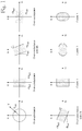
- FIG. 1 shows examples of operation characteristics of existing admittance protection functions presented on an admittance plane (B is susceptance and G is conductance).
- the shaded area in each of the operation characteristics determines the normal or non-operation area such that, if the neutral admittance is within this area, the protection does not operate and, if the neutral admittance is outside this area, then the protection operates.
- the over-admittance operation characteristic may be defined by setting an absolute value Y set of admittance Y which defines a circle on the admittance plane as shown.
- the over-conductance operation characteristic may be defined by lower (-G se t) and upper (+G set ) conductance settings and a tilt may be further set with an angle setting ⁇ as shown.
- the over-susceptance operation characteristic may be defined by lower (-B set ) and upper (+B set ) susceptance settings and a tilt may be further set with an angle setting a.
- a tilt may be further set with an angle setting a.
- EP1195875A2 relates to a method for identification of an impending fault condition in an electrical distribution system such as a compensated network.
- An object of the present invention is to provide a method and an apparatus for implementing the method so as to overcome the above problem or at least to alleviate the problem.
- the objects of the invention are achieved by a method, a computer program product and an apparatus which are characterized by what is stated in the independent claims.
- the preferred embodiments of the invention are disclosed in the dependent claims.
- the invention is based on the idea of utilizing zero sequence currents and voltages before an earth fault and during the earth fault for determining a neutral admittance, and comparing the determined neutral admittance, or a quantity indicative thereof, to a predetermined operation characteristic to detect a phase-to-earth fault on the three-phase electric line, wherein the predetermined operation characteristic, when presented on an admittance plane, defines a closed area such that the centre of the closed area is offset from the origin of the admittance plane towards a negative susceptance direction and/or towards a negative conductance direction.
- An advantage of the invention is that it provides a simplified operation function and characteristic, which can at the same time be valid for unearthed networks, high resistance earthed and/or compensated networks. Therefore, no change in the setting values are needed, if e.g. the earthing method is changed by e.g. disconnection of a compensation coil.
- the invention provides immunity against fault resistance and system unbalance by using delta-quantities in neutral admittance calculation. Therefore, a high sensitivity in terms of how high fault resistance can be detected can be obtained.
- the application of the invention is not limited to any specific system, but it can be used in connection with various three-phase electric systems to detect a phase-to-earth fault on a three-phase electric line of an electric network.
- the electric line can be a feeder, for example, and it may be an overhead-line or a cable or a combination of both.
- the electric power system in which the invention is implemented can be an electric transmission or distribution network or a component thereof, for example, and may comprise several feeders or sections.
- the use of the invention is not limited to systems employing 50 Hz or 60 Hz fundamental frequencies or to any specific voltage level.
- Figures 2 and 3 are simplified equivalent circuits for a three-phase electric network in which the invention can be used.
- Figure 2 shows a situation in which there is a fault in the background network
- Figure 3 shows a situation in which there is a fault in the electric line to be monitored.
- the figures show only the components necessary for understanding the invention.
- the exemplary network can be a medium voltage (e.g. 20 kV) distribution network fed through a substation comprising a transformer 10 and a busbar 20.
- the illustrated network also comprises electric line outlets, i.e. feeders, of which one 30 is shown separately.
- a 'background network' Other possible feeders as well as other network parts, except the line 30, are referred to as a 'background network' and have been represented by a single line outlet 40 although it should be noted that there may be any number of feeders or other network elements in the background network. There may also be several feeding substations. Further, the invention can be utilized with a switching station without a transformer 10, for example.
- the network is a three-phase network and the three phases of the three-phase electricity system are referred to as L1, L2, and L3.
- the functionality of the invention can be located in a possible relay unit (not shown) located at the beginning of the line 30 e.g. in the connection point between the line 30 and the busbar 20.
- Monitored current and voltage values are preferably obtained by a suitable measuring arrangement including e.g. current and voltage transducers (not shown in the figures) connected to the phases of the electricity system.
- a suitable measuring arrangement including e.g. current and voltage transducers (not shown in the figures) connected to the phases of the electricity system.
- these values are readily available and thus the implementation of the invention does not necessarily require any separate or specific measuring arrangements. How such values are obtained is of no relevance to the basic idea of the invention and depends on the particular electricity system to be monitored.
- Start of the neutral admittance calculation is preferably done as soon as an earth fault is detected.
- An earth fault in the electric network may be detected on the basis of the zero sequence voltage. It can be done in two alternative ways: either when amplitude of the residual voltage exceeds a pre-set value U 0set :
- Equation 3 The advantage of using equation 3 as a start criterion is the fact that due to network asymmetry, a large magnitude residual voltage may exist in the network during the healthy state. This may lead to a very high value of U 0set , which in turn results in insensitivity of the fault detection.
- the start criterion is based on change, not on the absolute value, and therefore sensitivity of fault detection is increased.
- An outside fault means that the fault is located outside the protected electric line 30. This can be achieved by setting the admittance characteristic so that the characteristic always covers the total line admittance of the electric line.
- the value for the total line admittance (sum of all phase admittances) can be determined on the basis of the earth-fault current value of the electric line: Y _ Fdtot ⁇ j * 3 ⁇ I 0Fd / U phase , where
- admittance characteristic settings could be updated utilizing equation 6 so that the settings, and thus the characteristic, match the current switching state of the electric line i.e. the total line admittance is covered by the admittance characteristic.
- the updating can be performed in real time, i.e. always when the switching state of the three-phase electric line changes. Alternatively, the updating can be performed at predetermined intervals, for example.
- Y _ Bgtot Y _ L 1 Bg + Y _ L 2 Bg + Y _ L 3 Bg
- G CC is the conductance of the resistor, which is connected in parallel with the compensation coil in case of compensated networks.
- B CC 0
- G CC is the conductance of the earthing resistor.
- Y CC 0.
- An inside fault means that the fault is located inside the protected electric line 30.
- the neutral admittance or a quantity indicative thereof, has been determined e.g. on the basis of equation 1, it is compared to a predetermined operation characteristic to detect a phase-to-earth fault on the three-phase electric line 30.
- the predetermined operation characteristic when presented on an admittance plane, defines a closed area such that the centre of the closed area is offset from the origin of the admittance plane towards a negative susceptance direction and/or towards a negative conductance direction.
- the comparison of the determined neutral admittance, or the quantity indicative thereof, to a predetermined operation characteristic to detect a phase-to-earth fault on the three-phase electric line preferably comprises determining whether the neutral admittance is inside or outside of said closed area defined by the predetermined operation characteristic on the admittance plane, and detecting a phase-to-earth fault on the three-phase electric line when the determined neutral admittance is determined to be outside of said closed area defined by the predetermined operation characteristic on the admittance plane.
- the closed area is a non-operation area in which the protection does not operate
- the area outside the closed area is an operation area in which the protection operates i.e. a phase-to-earth fault is detected on the three-phase electric line 30.
- the closed area is defined by a circle or an ellipse whose centre point is offset from the origin of the admittance plane towards the negative susceptance (B) direction and/or towards the negative conductance (G) direction.
- Figure 4 shows an example of an operation characteristic which comprises a circle 401, which is set-off from the admittance plane origin by settings GN1 and BN1.
- the circle radius is defined by setting YN1. Operation of the protection is achieved, when the determined neutral admittance moves outside the closed area defined by the circle 401.
- the settings GN1, BN1 and YN1 should be generally selected such that the admittance corresponding to the electric line 30 length ( Y Fdtot ) is within the closed area preferably with a suitable safety margin. The smaller the circle, the more sensitive the protection is. If the connection state of the electric line 30 to be protected changes, the settings should be adjusted accordingly. This can also be done automatically by determining the total line admittance by calculating the neutral admittance based on changes in the residual current and voltage during the healthy state using equation 6.
- the closed area is defined by a circle whose centre point is offset from the origin of the admittance plane towards the negative susceptance direction and/or towards the negative conductance direction such that a segment of the circle is excluded from the closed area which segment is defined by a line defined by a predetermined conductance value.
- the offset admittance circle 401 can be combined with one or more "classical" boundary lines, e.g. with a forward directional conductance boundary line 402 as illustrated in Figure 4 .
- the shaded segment 403 of the circle 401 is excluded from the closed area and thus belongs to the operation area surrounding the closed non-operation area.
- G max should be preferably set and used. However, if the compensation coil and parallel resistor are disconnected, this setting need not be changed.
- the closed area is a polygon having three or more sides defined by three or more lines, respectively.
- the operation characteristic is an off-set rectangle (the shaded area), whose reach is defined by settings B min , B max and G min , G max which define lines forming the sides of the rectangle.
- This operation scheme requires more setting parameters, but offers more flexibility and is useful especially in case of problematic network configurations.
- the G settings relate to the network components causing resistive current in the network such as a possible compensation coil and its parallel resistor.
- the imaginary part of the measured admittance is mainly due to the term G CC caused by the parallel resistor of the compensation coil.
- the settings G min and G max are preferably selected such that Gcc is outside the range defined by G min and G max .
- a suitable safety margin may be used.
- the settings B min and B max may be selected e.g. to correspond to the minimum and maximum switching situations of the electric line 30 to be protected. Again, a suitable safety margin may be used.
- One option is to determine parameters of a polygon shape admittance criterion by utilizing calculated neutral admittance based on changes in the residual current and voltage during the healthy state using equation 6. After determining the total line admittance of the present switching state using equation 6, then settings G min , G max , B min and B max can be determined using the following formulae:
- the benefit of the various suggested operation characteristics is that they can be applied to unearthed, high resistance earthed and also compensated networks. Also the number of settings is minimized.
- a faulted phase can be identified by calculating fault resistance estimates simultaneously for each phase:
- R F _ L 1 real U _ L 1 _ fault 3 ⁇ I _ 0 ⁇ ⁇ U _ 0 ⁇ ⁇ Y _ Fdtot
- R F _ L 2 real U _ L 2 _ fault 3 ⁇ I _ 0 ⁇ ⁇ U _ 0 ⁇ ⁇ Y _ Fdtot
- R F _ L 3 real U _ L 3 _ fault 3 ⁇ I _ 0 ⁇ ⁇ U _ 0 ⁇ ⁇ Y _ Fdtot
- Phase selection logic suggested in case only one out of the three fault resistance estimates provides positive value, this is the faulted phase with corresponding fault resistance value. In case two out of the three fault resistance estimates provides positive value, the faulted phase is selected on the basis of comparing the phase voltage magnitudes between the two candidates: the faulted phase is the phase with a lower phase voltage value.
- a multi-stage admittance protection concept could be implemented.
- the fault resistance estimate can be used to define operation speed.
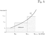
- Multiple fault resistance thresholds protection stages
- Different stages could be set e.g. at RF>, RF>>, RF>>>, RF>>>> with corresponding protection operation delays t>, t», t>>> and t>>>>.
- Figure 6 shows how an inverse type operation curve 601 is formed along with such protection stages.
- An apparatus may be implemented as one unit or as two or more separate units that are configured to implement the functionality of the various embodiments.
- the term 'unit' refers generally to a physical or logical entity, such as a physical device or a part thereof or a software routine.
- One or more of these units may reside in a protective relay device or equipment, for example.
- an apparatus may comprise a monitoring unit configured to monitor a zero sequence current on the three-phase electric line and a zero sequence voltage in the electric network; a detection unit configured to detect an earth fault in the electric network on the basis of the zero sequence voltage value, a determination unit configured to determine a difference between the zero sequence current before the earth fault and the zero sequence current during the earth fault, to determine a difference between the zero sequence voltage before the earth fault and the zero sequence voltage during the earth fault, and to determine a neutral admittance, or a quantity indicative thereof, on the basis of a ratio between the difference between the zero sequence currents and the difference between the zero sequence voltages, and a comparison unit configured to compare the determined neutral admittance, or the quantity indicative thereof, to a predetermined operation characteristic to detect a phase-to-earth fault on the three-phase electric line.
- An apparatus may be implemented by means of a computer or corresponding digital signal processing equipment provided with suitable software, for example.
- a computer or digital signal processing equipment preferably comprises at least a working memory (RAM) providing storage area for arithmetical operations and a central processing unit (CPU), such as a general-purpose digital signal processor.
- the CPU may comprise a set of registers, an arithmetic logic unit, and a control unit.
- the control unit is controlled by a sequence of program instructions transferred to the CPU from the RAM.
- the control unit may contain a number of microinstructions for basic operations. The implementation of microinstructions may vary depending on the CPU design.
- the program instructions may be coded by a programming language, which may be a high-level programming language, such as C, Java, etc., or a low-level programming language, such as a machine language, or an assembler.
- the computer may also have an operating system which may provide system services to a computer program written with the program instructions.
- the computer or other apparatus implementing the invention further preferably comprises suitable input means for receiving e.g. measurement and/or control data, which input means thus enable e.g. the monitoring of current and voltage quantities, and output means for outputting e.g. fault alarms and/or control data e.g. for controlling protection equipment such as switches, disconnectors and circuit-breakers. It is also possible to use a specific integrated circuit or circuits, and/or discrete components and devices for implementing the functionality according to any one of the embodiments.
- the invention can be implemented in existing system elements, such as various protective relays or similar devices, or by using separate dedicated elements or devices in a centralized or distributed manner.
- Present protective devices for electric systems such as protective relays, typically comprise processors and memory that can be utilized in the functions according to embodiments of the invention.
- all modifications and configurations required for implementing an embodiment of the invention e.g. in existing protective devices may be performed as software routines, which may be implemented as added or updated software routines.
- software can be provided as a computer program product comprising computer program code which, when run on a computer, causes the computer or corresponding arrangement to perform the functionality according to the invention as described above.
- Such a computer program code may be stored or generally embodied on a computer readable medium, such as suitable memory, e.g. a flash memory or a disc memory from which it is loadable to the unit or units executing the program code.
- suitable memory e.g. a flash memory or a disc memory from which it is loadable to the unit or units executing the program code.
- a computer program code implementing the invention may be loaded to the unit or units executing the computer program code via a suitable data network, for example, and it may replace or update a possibly existing program code.
Landscapes
- Physics & Mathematics (AREA)
- General Physics & Mathematics (AREA)
- Engineering & Computer Science (AREA)
- Power Engineering (AREA)
- Emergency Protection Circuit Devices (AREA)
- Remote Monitoring And Control Of Power-Distribution Networks (AREA)
- Locating Faults (AREA)
- Testing Of Short-Circuits, Discontinuities, Leakage, Or Incorrect Line Connections (AREA)
Claims (14)
- Procédé de détection d'un défaut de phase à la terre sur une ligne électrique triphasée d'un réseau électrique, le procédé comprenant :la surveillance d'un courant de séquence homopolaire sur la ligne électrique triphasée et d'une tension de séquence homopolaire dans le réseau électrique ;la détection d'un défaut à la terre dans le réseau électrique sur la base de la valeur de tension de séquence homopolaire ;la détermination d'une différence entre le courant de séquence homopolaire avant le défaut à la terre et le courant de séquence homopolaire pendant le défaut à la terre ; etla détermination d'une différence entre la tension de séquence homopolaire avant le défaut à la terre et la tension de séquence homopolaire pendant le défaut à la terre, caractérisé en ce que le procédé comprend :la détermination d'une admittance neutre, ou d'une quantité indicative associée, sur la base d'un rapport entre la différence entre les courants de séquence homopolaire et la différence entre les tensions de séquence homopolaire ; etla comparaison de l'admittance neutre déterminée, ou de la quantité indicative associée, à une caractéristique de fonctionnement prédéfinie pour détecter un défaut de phase à la terre sur la ligne électrique triphasée, la caractéristique de fonctionnement prédéfinie, lorsqu'elle est présentée sur un plan d'admittance, définissant une zone fermée de sorte que le centre de la zone fermée soit décalé de l'origine du plan d'admittance vers une direction de susceptance négative et/ou vers une direction de conductance négative.
- Procédé selon la revendication 1, caractérisé en ce que
la comparaison de l'admittance neutre déterminée, ou de la quantité indicative associée, à une caractéristique de fonctionnement prédéfinie pour détecter un défaut de phase à la terre sur la ligne électrique triphasée comprend :déterminer si l'admittance neutre est à l'intérieur ou à l'extérieur de ladite zone fermée définie par la caractéristique de fonctionnement prédéfinie sur le plan d'admittance ; etdétecter un défaut de phase à la terre sur la ligne électrique triphasée lorsque l'admittance neutre déterminée est déterminée comme étant en dehors de ladite zone fermée définie par la caractéristique de fonctionnement prédéfinie sur le plan d'admittance. - Procédé selon la revendication 1 ou 2, caractérisé en ce que la zone fermée est définie par un cercle ou une ellipse dont le point central est décalé de l'origine du plan d'admittance vers la direction de susceptance négative et/ou vers la direction de conductance négative.
- Procédé selon la revendication 1 ou 2, caractérisé en ce que la zone fermée est définie par un cercle dont le point central est décalé de l'origine du plan d'admittance vers la direction de susceptance négative et/ou vers la direction de conductance négative de sorte qu'un segment du cercle soit exclu de la zone fermée, lequel segment est défini par une ligne définie par une valeur de conductance prédéfinie.
- Procédé selon la revendication 1 ou 2, caractérisé en ce que la zone fermée est un polygone ayant trois côtés ou plus définis par trois lignes ou plus respectivement.
- Procédé selon l'une quelconque des revendications 1 à 5, caractérisé en ce que le procédé comprend la mise à jour de la caractéristique de fonctionnement prédéfinie lorsque l'état de commutation de la ligne électrique triphasée change ou à des intervalles prédéfinis.
- Produit-programme informatique comprenant un code de programme informatique, dans lequel l'exécution du code de programme dans un ordinateur amène l'ordinateur à réaliser les étapes du procédé selon l'une quelconque des revendications 1 à 6.
- Appareil de détection d'un défaut de phase à la terre sur une ligne électrique triphasée (30) d'un réseau électrique, l'appareil comprenant :des moyens permettant la surveillance d'un courant de séquence homopolaire sur la ligne électrique triphasée (30) et d'une tension de séquence homopolaire dans le réseau électrique ;des moyens permettant la détection d'un défaut à la terre dans le réseau électrique sur la base de la valeur de tension de séquence homopolaire ;des moyens permettant la détermination d'une différence entre le courant de séquence homopolaire avant le défaut à la terre et le courant de séquence homopolaire pendant le défaut à la terre ; etdes moyens permettant la détermination d'une différence entre la tension de séquence homopolaire avant le défaut à la terre et la tension de séquence homopolaire pendant le défaut à la terre, caractérisé en ce que l'appareil comprend :des moyens permettant la détermination d'une admittance neutre, ou d'une quantité indicative associée, sur la base d'un rapport entre la différence entre les courants de séquence homopolaire et la différence entre les tensions de séquence homopolaire ; etdes moyens permettant la comparaison de l'admittance neutre déterminée, ou de la quantité indicative associée, à une caractéristique de fonctionnement prédéfinie pour détecter un défaut de phase à la terre sur la ligne électrique triphasée, la caractéristique de fonctionnement prédéfinie, lorsqu'elle est présentée sur un plan d'admittance, définissant une zone fermée de sorte que le centre de la zone fermée soit décalé de l'origine du plan d'admittance vers une direction de susceptance négative et/ou vers une direction de conductance négative.
- Appareil selon la revendication 8, caractérisé en ce que
les moyens permettant la comparaison de l'admittance neutre déterminée, ou de la quantité indicative associée, à une caractéristique de fonctionnement prédéfinie pour détecter un défaut de phase à la terre sur la ligne électrique triphasée comprennent :des moyens permettant de déterminer si l'admittance neutre est à l'intérieur ou à l'extérieur de ladite zone fermée définie par la caractéristique de fonctionnement prédéfinie sur le plan d'admittance ; etdes moyens permettant de détecter un défaut de phase à la terre sur la ligne électrique triphasée lorsque l'admittance neutre déterminée est déterminée comme étant en dehors de ladite zone fermée définie par la caractéristique de fonctionnement prédéfinie sur le plan d'admittance. - Appareil selon la revendication 8 ou 9, caractérisé en ce que la zone fermée est définie par un cercle ou une ellipse dont le point central est décalé de l'origine du plan d'admittance vers la direction de susceptance négative et/ou vers la direction de conductance négative.
- Appareil selon la revendication 8 ou 9, caractérisé en ce que la zone fermée est définie par un cercle dont le point central est décalé de l'origine du plan d'admittance vers la direction de susceptance négative et/ou vers la direction de conductance négative de sorte qu'un segment du cercle soit exclu de la zone fermée, lequel segment est défini par une ligne définie par une valeur de conductance prédéfinie.
- Appareil selon la revendication 8 ou 9, caractérisé en ce que la zone fermée est un polygone ayant trois côtés ou plus définis par trois lignes ou plus respectivement.
- Appareil selon l'une quelconque des revendications 8 à 12, caractérisé en ce que l'appareil comprend des moyens pour mettre à jour la caractéristique de fonctionnement prédéfinie lorsque l'état de commutation de la ligne électrique triphasée change ou à des intervalles prédéfinis.
- Appareil selon l'une quelconque des revendications 8 à 13, caractérisé en ce que l'appareil comprend un relais de protection.
Priority Applications (5)
| Application Number | Priority Date | Filing Date | Title |
|---|---|---|---|
| EP08169969.6A EP2192416B1 (fr) | 2008-11-26 | 2008-11-26 | Procédé et appareil pour détecter le défaut de phase à la terre |
| CN200980147036XA CN102224427B (zh) | 2008-11-26 | 2009-11-20 | 用于检测相对地故障的方法和设备 |
| RU2011125624/28A RU2491563C2 (ru) | 2008-11-26 | 2009-11-20 | Способ и устройство для определения замыкания фазы на землю |
| PCT/FI2009/050942 WO2010061055A1 (fr) | 2008-11-26 | 2009-11-20 | Procédé et appareil pour détecter un défaut entre phase et terre |
| US13/113,708 US8717036B2 (en) | 2008-11-26 | 2011-05-23 | Method and apparatus for detecting a phase-to-earth fault |
Applications Claiming Priority (1)
| Application Number | Priority Date | Filing Date | Title |
|---|---|---|---|
| EP08169969.6A EP2192416B1 (fr) | 2008-11-26 | 2008-11-26 | Procédé et appareil pour détecter le défaut de phase à la terre |
Publications (2)
| Publication Number | Publication Date |
|---|---|
| EP2192416A1 EP2192416A1 (fr) | 2010-06-02 |
| EP2192416B1 true EP2192416B1 (fr) | 2018-01-03 |
Family
ID=40547540
Family Applications (1)
| Application Number | Title | Priority Date | Filing Date |
|---|---|---|---|
| EP08169969.6A Active EP2192416B1 (fr) | 2008-11-26 | 2008-11-26 | Procédé et appareil pour détecter le défaut de phase à la terre |
Country Status (5)
| Country | Link |
|---|---|
| US (1) | US8717036B2 (fr) |
| EP (1) | EP2192416B1 (fr) |
| CN (1) | CN102224427B (fr) |
| RU (1) | RU2491563C2 (fr) |
| WO (1) | WO2010061055A1 (fr) |
Families Citing this family (30)
| Publication number | Priority date | Publication date | Assignee | Title |
|---|---|---|---|---|
| WO2011156400A1 (fr) * | 2010-06-07 | 2011-12-15 | Abb Research Ltd. | Systèmes et procédés de caractérisation de dispositifs d'élimination de défauts |
| BR112013006956B1 (pt) * | 2010-09-24 | 2020-04-22 | Siemens Ag | dispositivo submarino de comutação de energia e métodos de operação do mesmo |
| EP2487766B1 (fr) * | 2011-02-11 | 2015-08-26 | ABB Technology AG | Procédé et appareil pour détecter un défaut à la terre |
| EP2490311B1 (fr) * | 2011-02-15 | 2017-08-23 | ABB Schweiz AG | Procédé et appareil pour détecter un défaut à la terre |
| EP2624397B1 (fr) * | 2012-02-03 | 2014-04-02 | ABB Technology AG | Procédé et appareil de détermination de direction de défaut |
| EP2639914B1 (fr) * | 2012-03-16 | 2015-07-22 | ABB Technology AG | Procédé et appareil pour adapter des paramètres de protection contre les défauts de terre dans un réseau électrique triphasé |
| CN102928731A (zh) * | 2012-11-06 | 2013-02-13 | 昆明理工大学 | 一种利用零序电流全量Hough变换的配电网故障选线方法 |
| CN103852688B (zh) * | 2012-11-30 | 2016-11-16 | 施耐德电器工业公司 | 用于确定接地故障的位置的方法和设备 |
| CN103176106B (zh) * | 2013-03-01 | 2014-12-24 | 江苏镇安电力设备有限公司 | 一种配出中性导体it系统单相接地故障选相方法 |
| CN104345197B (zh) * | 2013-07-24 | 2017-09-15 | 施耐德电器工业公司 | 在单相接地故障时估计零序电压的角度的方法及设备 |
| CN104914322B (zh) * | 2014-03-16 | 2019-09-27 | 田京涛 | 一种区域线路对地参数检测方法及在接地故障区域定位方面的应用 |
| US20150309085A1 (en) * | 2014-04-28 | 2015-10-29 | Rockwell Automation Technologies, Inc. | Calculating line-to-neutral voltages without a connection to a system neutral or earth ground |
| FI126434B (fi) * | 2015-06-03 | 2016-11-30 | Jyväskylän Energia Oy | Menetelmä kolmivaiheisen sähköverkon maasulkusuojauksessa |
| SE539485C2 (sv) * | 2016-05-20 | 2017-10-03 | Swedish Neutral Holding Ab | System och metod för lokalisering av jordfel i kraftnät |
| CN106646139B (zh) * | 2016-12-30 | 2019-04-16 | 华北电力大学 | 一种基于三相电流幅值分析的配电网故障定位方法 |
| AT519450B1 (de) * | 2017-02-09 | 2018-07-15 | Sprecher Automation Gmbh | Verfahren zur Steuerung eines Distanzschutzrelais durch Erkennung von Leiter-Erde-Fehlern |
| CN107179481B (zh) * | 2017-07-06 | 2019-06-14 | 中国矿业大学 | 环形中性点不接地配电网的单相接地故障选线方法 |
| RU2672663C1 (ru) * | 2017-11-30 | 2018-11-19 | федеральное государственное бюджетное образовательное учреждение высшего образования "Ивановский государственный энергетический университет имени В.И. Ленина" (ИГЭУ) | Способ защиты от однофазных замыканий на землю в электрических сетях среднего напряжения |
| RU2666169C1 (ru) * | 2017-12-29 | 2018-09-06 | федеральное государственное бюджетное образовательное учреждение высшего образования "Национальный исследовательский университет "МЭИ" (ФГБОУ ВО "НИУ "МЭИ") | Способ топографического поиска места замыкания на землю в воздушных сетях 10 кВ с изолированной нейтралью |
| CN108594071B (zh) * | 2018-04-18 | 2020-09-25 | 广东电网有限责任公司 | 一种中性点小电阻接地配网的单相接地故障检测方法 |
| CN112119556B (zh) * | 2018-05-18 | 2023-01-24 | Abb瑞士股份有限公司 | 用于在接地故障保护中使用的方法和设备 |
| EP3570400B1 (fr) | 2018-05-18 | 2022-01-26 | ABB Schweiz AG | Procédé et appareil à utiliser dans une protection de défaut à la terre |
| EP3570399B1 (fr) * | 2018-05-18 | 2022-03-16 | ABB Schweiz AG | Procédé et appareil à utiliser dans une protection de défaut à la terre |
| CN111157835B (zh) * | 2018-11-07 | 2023-01-24 | 国网电力科学研究院武汉南瑞有限责任公司 | 一种电网单相接地故障判断方法 |
| CN112526282B (zh) * | 2020-06-15 | 2022-05-10 | 国网湖北省电力有限公司黄冈供电公司 | 一种配网单相接地故障区段定位方法 |
| CN111768599B (zh) * | 2020-07-08 | 2021-08-10 | 安徽先兆科技有限公司 | Ac380v回路电气安全管控方法及系统 |
| CN112444756B (zh) * | 2020-10-21 | 2022-08-12 | 国网山东省电力公司泰安供电公司 | 一种基于零序工频电气分量耦合椭圆分布特征的小电流不接地选线方法 |
| CN112485595B (zh) * | 2020-11-30 | 2024-04-09 | 云南电网有限责任公司电力科学研究院 | 一种配电网接地故障选线保护方法及装置 |
| CN112858837B (zh) * | 2021-01-13 | 2022-04-08 | 清华大学 | 一种判断输电线路高阻故障方向的方法及装置 |
| WO2023022780A1 (fr) * | 2021-08-17 | 2023-02-23 | S&C Electric Company | Sectionneur de défaut à la terre pour réseau de distribution d'énergie électrique |
Family Cites Families (13)
| Publication number | Priority date | Publication date | Assignee | Title |
|---|---|---|---|---|
| SU761953A1 (ru) * | 1974-08-30 | 1980-09-07 | Abram S Malyj | Способ определения расстояние до места короткого замыкания вптб |
| SU1255968A1 (ru) * | 1984-12-10 | 1986-09-07 | Производственное Энергетическое Объединение "Алтайэнерго" | Способ определени места короткого замыкани на землю на линии электропередачи |
| US4809123A (en) * | 1986-04-14 | 1989-02-28 | Isco, Inc. | Ground fault detector for high-voltage DC power supplies |
| FI106985B (fi) * | 1999-09-23 | 2001-05-15 | Abb Substation Automation Oy | Menetelmä sähkönjakeluverkon maasulkuvian etäisyyden määrittämiseksi laskennallisesti rengaskytkennässä |
| FI108894B (fi) * | 2000-09-22 | 2002-04-15 | Abb Substation Automation Oy | Menetelmä sähköverkon vikaantumassa olevan tai viallisen lähdön tai haaran ilmaisemiseksi esimerkiksi kompensoidussa verkossa |
| US6741943B2 (en) | 2001-09-13 | 2004-05-25 | Abb Power Automation Ltd. | Crossover fault classification for power lines with parallel circuits |
| DE10151775A1 (de) * | 2001-10-19 | 2003-05-08 | Alstom | Verfahren zur Berechnung einer Distanz eines Fehlerorts eines einpoligen Erdfehlers von einem Messort in einem elektrischen Energieversorgungsnetz |
| US6785105B2 (en) * | 2002-08-05 | 2004-08-31 | Schweitzer Engineering Laboratories, Inc. | Ground fault detection system for ungrounded power systems |
| FI118492B (fi) * | 2005-05-17 | 2007-11-30 | Abb Oy | Järjestelmä ja menetelmä maasulkuvian sijainnin määrittämiseksi |
| US7940054B2 (en) * | 2006-10-16 | 2011-05-10 | Schweitzer Engineering Laboratories, Inc. | System and method to zero-sequence verify ground return path integrity by comparing measured zero-sequence current in an autotransformer with a second zero-sequence current source |
| ATE513223T1 (de) * | 2006-12-29 | 2011-07-15 | Abb Technology Ag | System und verfahren zur ortung eines einpoligen erdschlusses |
| KR100883777B1 (ko) * | 2007-01-26 | 2009-02-18 | 명지대학교 산학협력단 | 배전자동화시스템에서 단말장치의 고장표시 생성방법 |
| EP2000811B1 (fr) * | 2007-05-18 | 2017-12-13 | ABB Schweiz AG | Procédé de détermination de la localisation du défaut phase-terre |
-
2008
- 2008-11-26 EP EP08169969.6A patent/EP2192416B1/fr active Active
-
2009
- 2009-11-20 WO PCT/FI2009/050942 patent/WO2010061055A1/fr active Application Filing
- 2009-11-20 CN CN200980147036XA patent/CN102224427B/zh active Active
- 2009-11-20 RU RU2011125624/28A patent/RU2491563C2/ru active
-
2011
- 2011-05-23 US US13/113,708 patent/US8717036B2/en active Active
Non-Patent Citations (1)
| Title |
|---|
| LORENC J ET AL: "Admittance criteria for earth fault detection in substation automation systems in Polish distribution power networks", ELECTRICITY DISTRIBUTION. PART 1: CONTRIBUTIONS. CIRED. 14TH INTERNATI ONAL CONFERENCE AND EXHIBITION ON (IEE CONF. PUBL. NO. 438), LONDON, UK,IEE, UK, vol. 4, 2 June 1997 (1997-06-02), pages 19/1 - 19/5, XP006506450, ISBN: 978-0-85296-674-7 * |
Also Published As
| Publication number | Publication date |
|---|---|
| RU2491563C2 (ru) | 2013-08-27 |
| WO2010061055A1 (fr) | 2010-06-03 |
| US8717036B2 (en) | 2014-05-06 |
| CN102224427A (zh) | 2011-10-19 |
| US20110298468A1 (en) | 2011-12-08 |
| RU2011125624A (ru) | 2013-01-10 |
| EP2192416A1 (fr) | 2010-06-02 |
| CN102224427B (zh) | 2013-09-25 |
Similar Documents
| Publication | Publication Date | Title |
|---|---|---|
| EP2192416B1 (fr) | Procédé et appareil pour détecter le défaut de phase à la terre | |
| US11522355B2 (en) | Method and apparatus for use in earth-fault protection | |
| EP2113778B1 (fr) | Procédé et système de détermination de la localisation du défaut phase-phase ou triphasé | |
| US11831146B2 (en) | Method and apparatus for use in earth-fault protection | |
| RU2631025C2 (ru) | Обнаружение направления слабоустойчивого короткого замыкания на землю среднего напряжения с помощью линейной корреляции | |
| EP2487766B1 (fr) | Procédé et appareil pour détecter un défaut à la terre | |
| US10191102B2 (en) | Automatic current transformer polarity correction | |
| CN103529356B (zh) | 用于确定距相对地故障的距离的方法和设备 | |
| EP2402774B1 (fr) | Procédé et appareil pour définir la distance d'un défaut de phase à la terre | |
| EP2490311B1 (fr) | Procédé et appareil pour détecter un défaut à la terre | |
| EP2639914B1 (fr) | Procédé et appareil pour adapter des paramètres de protection contre les défauts de terre dans un réseau électrique triphasé | |
| EP3107170B1 (fr) | Procédé et appareil pour l'adaptation automatique d'une protection de défaut à la terre | |
| CN112119556B (zh) | 用于在接地故障保护中使用的方法和设备 | |
| EP4322354A1 (fr) | Procédé et appareil de protection différentielle d'une connexion électrique triphasé | |
| CN111512512B (zh) | 使用传输线路的多终端测量的相位选择 | |
| US20230349683A1 (en) | Method and device for line protection |
Legal Events
| Date | Code | Title | Description |
|---|---|---|---|
| PUAI | Public reference made under article 153(3) epc to a published international application that has entered the european phase |
Free format text: ORIGINAL CODE: 0009012 |
|
| AK | Designated contracting states |
Kind code of ref document: A1 Designated state(s): AT BE BG CH CY CZ DE DK EE ES FI FR GB GR HR HU IE IS IT LI LT LU LV MC MT NL NO PL PT RO SE SI SK TR |
|
| AX | Request for extension of the european patent |
Extension state: AL BA MK RS |
|
| 17P | Request for examination filed |
Effective date: 20101012 |
|
| AKX | Designation fees paid |
Designated state(s): AT BE BG CH CY CZ DE DK EE ES FI FR GB GR HR HU IE IS IT LI LT LU LV MC MT NL NO PL PT RO SE SI SK TR |
|
| 17Q | First examination report despatched |
Effective date: 20150828 |
|
| RAP1 | Party data changed (applicant data changed or rights of an application transferred) |
Owner name: ABB SCHWEIZ AG |
|
| REG | Reference to a national code |
Ref country code: DE Ref legal event code: R079 Ref document number: 602008053570 Country of ref document: DE Free format text: PREVIOUS MAIN CLASS: G01R0031080000 Ipc: G01R0031020000 |
|
| GRAP | Despatch of communication of intention to grant a patent |
Free format text: ORIGINAL CODE: EPIDOSNIGR1 |
|
| STAA | Information on the status of an ep patent application or granted ep patent |
Free format text: STATUS: GRANT OF PATENT IS INTENDED |
|
| RIC1 | Information provided on ipc code assigned before grant |
Ipc: G01R 31/02 20060101AFI20170428BHEP Ipc: G01R 31/08 20060101ALI20170428BHEP |
|
| INTG | Intention to grant announced |
Effective date: 20170530 |
|
| RIN1 | Information on inventor provided before grant (corrected) |
Inventor name: WAHLROOS, ARI Inventor name: ALTONEN, JANNE |
|
| GRAJ | Information related to disapproval of communication of intention to grant by the applicant or resumption of examination proceedings by the epo deleted |
Free format text: ORIGINAL CODE: EPIDOSDIGR1 |
|
| STAA | Information on the status of an ep patent application or granted ep patent |
Free format text: STATUS: EXAMINATION IS IN PROGRESS |
|
| GRAR | Information related to intention to grant a patent recorded |
Free format text: ORIGINAL CODE: EPIDOSNIGR71 |
|
| GRAS | Grant fee paid |
Free format text: ORIGINAL CODE: EPIDOSNIGR3 |
|
| STAA | Information on the status of an ep patent application or granted ep patent |
Free format text: STATUS: GRANT OF PATENT IS INTENDED |
|
| INTC | Intention to grant announced (deleted) | ||
| GRAA | (expected) grant |
Free format text: ORIGINAL CODE: 0009210 |
|
| STAA | Information on the status of an ep patent application or granted ep patent |
Free format text: STATUS: THE PATENT HAS BEEN GRANTED |
|
| INTG | Intention to grant announced |
Effective date: 20171030 |
|
| AK | Designated contracting states |
Kind code of ref document: B1 Designated state(s): AT BE BG CH CY CZ DE DK EE ES FI FR GB GR HR HU IE IS IT LI LT LU LV MC MT NL NO PL PT RO SE SI SK TR |
|
| REG | Reference to a national code |
Ref country code: GB Ref legal event code: FG4D |
|
| REG | Reference to a national code |
Ref country code: CH Ref legal event code: EP Ref country code: AT Ref legal event code: REF Ref document number: 960783 Country of ref document: AT Kind code of ref document: T Effective date: 20180115 |
|
| REG | Reference to a national code |
Ref country code: IE Ref legal event code: FG4D |
|
| REG | Reference to a national code |
Ref country code: DE Ref legal event code: R096 Ref document number: 602008053570 Country of ref document: DE |
|
| REG | Reference to a national code |
Ref country code: NL Ref legal event code: MP Effective date: 20180103 |
|
| REG | Reference to a national code |
Ref country code: LT Ref legal event code: MG4D |
|
| REG | Reference to a national code |
Ref country code: AT Ref legal event code: MK05 Ref document number: 960783 Country of ref document: AT Kind code of ref document: T Effective date: 20180103 |
|
| PG25 | Lapsed in a contracting state [announced via postgrant information from national office to epo] |
Ref country code: NL Free format text: LAPSE BECAUSE OF FAILURE TO SUBMIT A TRANSLATION OF THE DESCRIPTION OR TO PAY THE FEE WITHIN THE PRESCRIBED TIME-LIMIT Effective date: 20180103 |
|
| PG25 | Lapsed in a contracting state [announced via postgrant information from national office to epo] |
Ref country code: LT Free format text: LAPSE BECAUSE OF FAILURE TO SUBMIT A TRANSLATION OF THE DESCRIPTION OR TO PAY THE FEE WITHIN THE PRESCRIBED TIME-LIMIT Effective date: 20180103 Ref country code: ES Free format text: LAPSE BECAUSE OF FAILURE TO SUBMIT A TRANSLATION OF THE DESCRIPTION OR TO PAY THE FEE WITHIN THE PRESCRIBED TIME-LIMIT Effective date: 20180103 Ref country code: NO Free format text: LAPSE BECAUSE OF FAILURE TO SUBMIT A TRANSLATION OF THE DESCRIPTION OR TO PAY THE FEE WITHIN THE PRESCRIBED TIME-LIMIT Effective date: 20180403 Ref country code: HR Free format text: LAPSE BECAUSE OF FAILURE TO SUBMIT A TRANSLATION OF THE DESCRIPTION OR TO PAY THE FEE WITHIN THE PRESCRIBED TIME-LIMIT Effective date: 20180103 Ref country code: CY Free format text: LAPSE BECAUSE OF FAILURE TO SUBMIT A TRANSLATION OF THE DESCRIPTION OR TO PAY THE FEE WITHIN THE PRESCRIBED TIME-LIMIT Effective date: 20180103 |
|
| PG25 | Lapsed in a contracting state [announced via postgrant information from national office to epo] |
Ref country code: LV Free format text: LAPSE BECAUSE OF FAILURE TO SUBMIT A TRANSLATION OF THE DESCRIPTION OR TO PAY THE FEE WITHIN THE PRESCRIBED TIME-LIMIT Effective date: 20180103 Ref country code: SE Free format text: LAPSE BECAUSE OF FAILURE TO SUBMIT A TRANSLATION OF THE DESCRIPTION OR TO PAY THE FEE WITHIN THE PRESCRIBED TIME-LIMIT Effective date: 20180103 Ref country code: PL Free format text: LAPSE BECAUSE OF FAILURE TO SUBMIT A TRANSLATION OF THE DESCRIPTION OR TO PAY THE FEE WITHIN THE PRESCRIBED TIME-LIMIT Effective date: 20180103 Ref country code: GR Free format text: LAPSE BECAUSE OF FAILURE TO SUBMIT A TRANSLATION OF THE DESCRIPTION OR TO PAY THE FEE WITHIN THE PRESCRIBED TIME-LIMIT Effective date: 20180404 Ref country code: BG Free format text: LAPSE BECAUSE OF FAILURE TO SUBMIT A TRANSLATION OF THE DESCRIPTION OR TO PAY THE FEE WITHIN THE PRESCRIBED TIME-LIMIT Effective date: 20180403 Ref country code: IS Free format text: LAPSE BECAUSE OF FAILURE TO SUBMIT A TRANSLATION OF THE DESCRIPTION OR TO PAY THE FEE WITHIN THE PRESCRIBED TIME-LIMIT Effective date: 20180503 Ref country code: AT Free format text: LAPSE BECAUSE OF FAILURE TO SUBMIT A TRANSLATION OF THE DESCRIPTION OR TO PAY THE FEE WITHIN THE PRESCRIBED TIME-LIMIT Effective date: 20180103 |
|
| REG | Reference to a national code |
Ref country code: DE Ref legal event code: R097 Ref document number: 602008053570 Country of ref document: DE |
|
| PG25 | Lapsed in a contracting state [announced via postgrant information from national office to epo] |
Ref country code: EE Free format text: LAPSE BECAUSE OF FAILURE TO SUBMIT A TRANSLATION OF THE DESCRIPTION OR TO PAY THE FEE WITHIN THE PRESCRIBED TIME-LIMIT Effective date: 20180103 Ref country code: RO Free format text: LAPSE BECAUSE OF FAILURE TO SUBMIT A TRANSLATION OF THE DESCRIPTION OR TO PAY THE FEE WITHIN THE PRESCRIBED TIME-LIMIT Effective date: 20180103 |
|
| PLBE | No opposition filed within time limit |
Free format text: ORIGINAL CODE: 0009261 |
|
| STAA | Information on the status of an ep patent application or granted ep patent |
Free format text: STATUS: NO OPPOSITION FILED WITHIN TIME LIMIT |
|
| PG25 | Lapsed in a contracting state [announced via postgrant information from national office to epo] |
Ref country code: SK Free format text: LAPSE BECAUSE OF FAILURE TO SUBMIT A TRANSLATION OF THE DESCRIPTION OR TO PAY THE FEE WITHIN THE PRESCRIBED TIME-LIMIT Effective date: 20180103 Ref country code: CZ Free format text: LAPSE BECAUSE OF FAILURE TO SUBMIT A TRANSLATION OF THE DESCRIPTION OR TO PAY THE FEE WITHIN THE PRESCRIBED TIME-LIMIT Effective date: 20180103 Ref country code: DK Free format text: LAPSE BECAUSE OF FAILURE TO SUBMIT A TRANSLATION OF THE DESCRIPTION OR TO PAY THE FEE WITHIN THE PRESCRIBED TIME-LIMIT Effective date: 20180103 |
|
| 26N | No opposition filed |
Effective date: 20181005 |
|
| PG25 | Lapsed in a contracting state [announced via postgrant information from national office to epo] |
Ref country code: SI Free format text: LAPSE BECAUSE OF FAILURE TO SUBMIT A TRANSLATION OF THE DESCRIPTION OR TO PAY THE FEE WITHIN THE PRESCRIBED TIME-LIMIT Effective date: 20180103 |
|
| REG | Reference to a national code |
Ref country code: CH Ref legal event code: PL |
|
| PG25 | Lapsed in a contracting state [announced via postgrant information from national office to epo] |
Ref country code: LU Free format text: LAPSE BECAUSE OF NON-PAYMENT OF DUE FEES Effective date: 20181126 Ref country code: MC Free format text: LAPSE BECAUSE OF FAILURE TO SUBMIT A TRANSLATION OF THE DESCRIPTION OR TO PAY THE FEE WITHIN THE PRESCRIBED TIME-LIMIT Effective date: 20180103 |
|
| REG | Reference to a national code |
Ref country code: BE Ref legal event code: MM Effective date: 20181130 |
|
| REG | Reference to a national code |
Ref country code: IE Ref legal event code: MM4A |
|
| PG25 | Lapsed in a contracting state [announced via postgrant information from national office to epo] |
Ref country code: CH Free format text: LAPSE BECAUSE OF NON-PAYMENT OF DUE FEES Effective date: 20181130 Ref country code: LI Free format text: LAPSE BECAUSE OF NON-PAYMENT OF DUE FEES Effective date: 20181130 |
|
| PG25 | Lapsed in a contracting state [announced via postgrant information from national office to epo] |
Ref country code: IE Free format text: LAPSE BECAUSE OF NON-PAYMENT OF DUE FEES Effective date: 20181126 |
|
| REG | Reference to a national code |
Ref country code: DE Ref legal event code: R079 Ref document number: 602008053570 Country of ref document: DE Free format text: PREVIOUS MAIN CLASS: G01R0031020000 Ipc: G01R0031500000 |
|
| PG25 | Lapsed in a contracting state [announced via postgrant information from national office to epo] |
Ref country code: BE Free format text: LAPSE BECAUSE OF NON-PAYMENT OF DUE FEES Effective date: 20181130 |
|
| PG25 | Lapsed in a contracting state [announced via postgrant information from national office to epo] |
Ref country code: MT Free format text: LAPSE BECAUSE OF NON-PAYMENT OF DUE FEES Effective date: 20181126 |
|
| PG25 | Lapsed in a contracting state [announced via postgrant information from national office to epo] |
Ref country code: TR Free format text: LAPSE BECAUSE OF FAILURE TO SUBMIT A TRANSLATION OF THE DESCRIPTION OR TO PAY THE FEE WITHIN THE PRESCRIBED TIME-LIMIT Effective date: 20180103 |
|
| PG25 | Lapsed in a contracting state [announced via postgrant information from national office to epo] |
Ref country code: PT Free format text: LAPSE BECAUSE OF FAILURE TO SUBMIT A TRANSLATION OF THE DESCRIPTION OR TO PAY THE FEE WITHIN THE PRESCRIBED TIME-LIMIT Effective date: 20180103 |
|
| PG25 | Lapsed in a contracting state [announced via postgrant information from national office to epo] |
Ref country code: HU Free format text: LAPSE BECAUSE OF FAILURE TO SUBMIT A TRANSLATION OF THE DESCRIPTION OR TO PAY THE FEE WITHIN THE PRESCRIBED TIME-LIMIT; INVALID AB INITIO Effective date: 20081126 |
|
| PGFP | Annual fee paid to national office [announced via postgrant information from national office to epo] |
Ref country code: GB Payment date: 20231123 Year of fee payment: 16 |
|
| PGFP | Annual fee paid to national office [announced via postgrant information from national office to epo] |
Ref country code: IT Payment date: 20231124 Year of fee payment: 16 Ref country code: FR Payment date: 20231120 Year of fee payment: 16 Ref country code: FI Payment date: 20231121 Year of fee payment: 16 Ref country code: DE Payment date: 20231121 Year of fee payment: 16 |