EP2192382A1 - Microelectromechanical gyroscope with rotary driving motion and improved electrical properties - Google Patents
Microelectromechanical gyroscope with rotary driving motion and improved electrical properties Download PDFInfo
- Publication number
- EP2192382A1 EP2192382A1 EP09177114A EP09177114A EP2192382A1 EP 2192382 A1 EP2192382 A1 EP 2192382A1 EP 09177114 A EP09177114 A EP 09177114A EP 09177114 A EP09177114 A EP 09177114A EP 2192382 A1 EP2192382 A1 EP 2192382A1
- Authority
- EP
- European Patent Office
- Prior art keywords
- horizontal axis
- sensing
- pair
- sensing masses
- masses
- Prior art date
- Legal status (The legal status is an assumption and is not a legal conclusion. Google has not performed a legal analysis and makes no representation as to the accuracy of the status listed.)
- Granted
Links
- 238000001514 detection method Methods 0.000 claims abstract description 39
- 239000000758 substrate Substances 0.000 claims abstract description 14
- 230000004044 response Effects 0.000 claims abstract description 5
- 230000005484 gravity Effects 0.000 claims description 11
- 239000003990 capacitor Substances 0.000 claims description 5
- 230000035945 sensitivity Effects 0.000 description 12
- 238000006073 displacement reaction Methods 0.000 description 10
- 230000001133 acceleration Effects 0.000 description 7
- 238000004519 manufacturing process Methods 0.000 description 3
- 239000000463 material Substances 0.000 description 3
- 239000004065 semiconductor Substances 0.000 description 3
- 238000005516 engineering process Methods 0.000 description 2
- 230000006355 external stress Effects 0.000 description 2
- 230000006872 improvement Effects 0.000 description 2
- 238000000034 method Methods 0.000 description 2
- 238000012986 modification Methods 0.000 description 2
- 230000004048 modification Effects 0.000 description 2
- 230000010355 oscillation Effects 0.000 description 2
- 229910021420 polycrystalline silicon Inorganic materials 0.000 description 2
- 230000005483 Hooke's law Effects 0.000 description 1
- 238000003486 chemical etching Methods 0.000 description 1
- 238000010276 construction Methods 0.000 description 1
- 238000010586 diagram Methods 0.000 description 1
- 238000009826 distribution Methods 0.000 description 1
- 230000036039 immunity Effects 0.000 description 1
- 238000005459 micromachining Methods 0.000 description 1
- 230000003534 oscillatory effect Effects 0.000 description 1
- 230000003071 parasitic effect Effects 0.000 description 1
- 229910052710 silicon Inorganic materials 0.000 description 1
- 239000010703 silicon Substances 0.000 description 1
- 238000005549 size reduction Methods 0.000 description 1
Images


Classifications
-
- G—PHYSICS
- G01—MEASURING; TESTING
- G01C—MEASURING DISTANCES, LEVELS OR BEARINGS; SURVEYING; NAVIGATION; GYROSCOPIC INSTRUMENTS; PHOTOGRAMMETRY OR VIDEOGRAMMETRY
- G01C19/00—Gyroscopes; Turn-sensitive devices using vibrating masses; Turn-sensitive devices without moving masses; Measuring angular rate using gyroscopic effects
- G01C19/56—Turn-sensitive devices using vibrating masses, e.g. vibratory angular rate sensors based on Coriolis forces
- G01C19/5705—Turn-sensitive devices using vibrating masses, e.g. vibratory angular rate sensors based on Coriolis forces using masses driven in reciprocating rotary motion about an axis
- G01C19/5712—Turn-sensitive devices using vibrating masses, e.g. vibratory angular rate sensors based on Coriolis forces using masses driven in reciprocating rotary motion about an axis the devices involving a micromechanical structure
-
- Y—GENERAL TAGGING OF NEW TECHNOLOGICAL DEVELOPMENTS; GENERAL TAGGING OF CROSS-SECTIONAL TECHNOLOGIES SPANNING OVER SEVERAL SECTIONS OF THE IPC; TECHNICAL SUBJECTS COVERED BY FORMER USPC CROSS-REFERENCE ART COLLECTIONS [XRACs] AND DIGESTS
- Y10—TECHNICAL SUBJECTS COVERED BY FORMER USPC
- Y10T—TECHNICAL SUBJECTS COVERED BY FORMER US CLASSIFICATION
- Y10T29/00—Metal working
- Y10T29/49—Method of mechanical manufacture
- Y10T29/49002—Electrical device making
Definitions
- the present invention relates to a microelectromechanical structure, in particular a biaxial or triaxial gyroscope, provided with a rotary driving movement and improved electrical characteristics, in particular in terms of sensitivity in the detection of angular velocities.
- micromachining techniques enable manufacturing of microelectromechanical structures or systems (MEMS) within layers of semiconductor material, which have been deposited (for example, a polycrystalline-silicon layer) or grown (for example, an epitaxial layer) on sacrificial layers, which are removed via chemical etching.
- MEMS microelectromechanical structures or systems
- Inertial sensors, accelerometers, and gyroscopes obtained with this technology are having an increasing success, for example, in the automotive field, in inertial navigation, or in the field of portable devices.
- gyroscopes made of semiconductor material obtained with MEMS technology. These gyroscopes operate on the basis of the theorem of relative accelerations, exploiting the Coriolis acceleration.
- Coriolis force an apparent force, referred to as "Coriolis force”
- the mobile mass is supported via springs that enable a displacement thereof in the direction of the apparent force.
- the displacement is proportional to the apparent force, in such a way that from the displacement of the mobile mass it is possible to detect the Coriolis force and the value of the angular velocity that has generated it.
- the displacement of the mobile mass can, for example, be detected in a capacitive way by determining, in resonance conditions, the variations of capacitance caused by the movement of mobile electrodes, fixed with respect to the mobile mass and combfingered with fixed electrodes.
- This microelectromechanical sensor comprises a single driving mass, anchored to a substrate in a single central point, and actuated with rotary motion about an axis passing through the central point and orthogonal to the plane of the driving mass.
- the movement of rotation of the driving mass makes it possible to obtain in the plane of the mass two components of driving velocity orthogonal with respect to one another.
- Through openings are provided within the driving mass, and corresponding sensing masses are arranged in the through openings; the sensing masses are enclosed in the overall dimensions of the driving mass, are suspended with respect to the substrate, and are connected to the driving mass via flexible elements.
- Each sensing mass is fixed with respect to the driving mass during its rotary motion, and has a further degree of freedom of movement as a function of an external stress, in particular a Coriolis force, acting on the sensor.
- the flexible elements thanks to their particular construction, enable the sensing masses to perform a rotary movement of detection about an axis belonging to the plane of the sensor, or alternatively a linear movement of detection along an axis belonging to the plane of the sensor, respectively, in response to a Coriolis acceleration acting in a direction perpendicular to the plane and to a Coriolis acceleration acting in a direction belonging to the plane.
- the movement of detection is in any case substantially decoupled from the movement of actuation of the driving mass.
- This microelectromechanical structure in addition to being compact (in so far as it envisages a single driving mass enclosing in its overall dimensions a number of sensing masses), makes it possible to obtain with minor structural modifications, a uniaxial, biaxial, or triaxial gyroscope (and/or possibly an accelerometer, according to the electrical connections implemented), at the same time ensuring an excellent decoupling of the driving dynamics from the detection dynamics.
- Figure 1 shows an exemplary embodiment of a triaxial microelectromechanical gyroscope, designated by 1, according to the teachings contained in the aforesaid patent applications.
- the gyroscope 1 is made in a die 2, comprising a substrate 2a made of semiconductor material (for example, silicon), and a frame 2b defining inside it an open region 2c; the open region 2c overlies the substrate 2a, and is designed to house detection structures of the gyroscope 1 (as described in detail hereinafter).
- the open region 2c has a generally square or rectangular configuration in a horizontal plane (in what follows, plane of the sensor xy), defined by a first horizontal axis x and a second horizontal axis y, fixed with respect to the die 2.
- the frame 2b has sides that are substantially parallel to the horizontal axes x, y.
- Contact pads 2d are arranged along a side of the frame 2b, aligned, for example, along the first horizontal axis x. In a way not illustrated, the die pads 2d enable electrical contact from outside of the detection structures of the gyroscope 1.
- the die pads 2d have an axis of symmetry, in this case coinciding with the second horizontal axis y (orthogonal to their direction of alignment), and are arranged in equal number and in a specular way on opposite sides of the second horizontal axis y.
- first and second horizontal axes x, y correspond to a first axis of detection and to a second axis of detection of the gyroscope 1 (more precisely, to a pitch axis and to a roll axis), about which corresponding pitch and roll angular velocities ⁇ x and ⁇ y are detected.
- the gyroscope 1 comprises a driving structure, housed within the open region 2c and including a driving mass 3 and a driving assembly 4.
- the driving mass 3 has a generally circular geometry with radial symmetry, with a substantially planar configuration having a main extension in the plane of the sensor xy, and a negligible dimension, with respect to the main extension, in a direction parallel to a vertical axis z, forming with the first and second horizontal axes x, y a set of three orthogonal axes, fixed with respect to the die 2.
- the driving mass 3 has in the plane of the sensor xy basically the shape of an annulus, and defines at the center an empty space 6, the center O of which coincides with the center of gravity and the center of symmetry of the entire structure.
- the driving mass 3 is anchored to the substrate 2a by means of a first anchorage 7a set in an area corresponding to the center O, to which it is connected through first elastic anchorage elements 8a.
- the first elastic anchorage elements 8a depart, forming a cross, from the center O, parallel to the first and second horizontal axes x, y.
- the driving mass 3 is anchored to the substrate 2a by means of further anchorages 7b, set on the outside of the same driving mass 3, to which it is connected by means of further elastic anchorage elements 8b.
- the further elastic anchorage elements 8b are of the folded type, are four in number, and are set aligned in pairs along the first and second horizontal axes x, y; accordingly, the further anchorages 7b are arranged, in pairs, on opposite sides of the driving mass 3 with respect to the empty space 6, at the ends of a cross centered in the center O.
- the first and further elastic anchorage elements 8a, 8b enable a rotary movement of the driving mass 3 about an axis of actuation passing through the center O, parallel to the vertical axis z and perpendicular to the plane of the sensor xy.
- the driving mass 3 has: a first pair of first through openings 9a, 9b, aligned in a diametric direction along the first horizontal axis x (pitch axis), and set on opposite sides with respect to the empty space 6; and a second pair of first through openings 9c, 9d, aligned in a diametric direction along the second horizontal axis y (roll axis), and set on opposite sides with respect to the empty space 6.
- each of the first through opening 9a-9d has in the plane of the sensor xy the shape of a radial sector of an annulus, having arc-shaped internal and external sides and radially-extending lateral sides.
- the through openings 9a-9b of the first pair are symmetrical with respect to the second horizontal axis y
- the through openings 9c-9d of the second pair are symmetrical with respect to the first horizontal axis x.
- the driving mass 3 has a pair of second through openings 26a, 26b, having in plan view a substantially rectangular shape, aligned in a radial direction (in the example of Figure 1 in a direction inclined by 45° with respect to the first horizontal axis x or the second horizontal axis y), and having a main extension in the same radial direction.
- the driving assembly 4 comprises a plurality of driven arms 10, extending externally from the driving mass 3 in a radial direction and in such a way that they are set at equal angular distances apart, and a plurality of first and second driving arms 12a, 12b, which extend parallel to, and on opposite sides of, respective driven arms 10.
- Each driven arm 10 carries a plurality of first electrodes 13, extending perpendicular to, and on either side of, the same driven arm.
- each of the first and second driving arms 12a, 12b carries respective second electrodes 14a, 14b, which extend towards the respective driven arm 10 and are combfingered with the corresponding first electrodes 13.
- the first driving arms 12a are arranged all on one and the same side of the respective driven arms 10, and are biased all at one and the same first voltage.
- the second driving arms 12b are arranged all on the opposite side of the respective driven arms 10, and are biased all at one and the same second voltage.
- a driving circuit (not illustrated) is connected to the second electrodes 14a, 14b for applying the first and second voltages and determining, by means of the mutual and alternating attraction of the electrodes, an oscillatory rotary movement of the driving mass 3 about the axis of actuation, at a given frequency of oscillation.
- the gyroscope 1 further comprises a first pair of acceleration sensors with axis parallel to the vertical axis z, and in particular a first pair of first sensing masses 16a, 16b, set within a respective first through opening 9a, 9b so as to be completely enclosed and contained within the overall dimensions of the driving mass 3 in the plane of the sensor xy.
- Each of the first sensing masses 16a, 16b has a shape corresponding to that of the respective through opening, and consequently has, in a plan view, the general shape of a radial annulus sector.
- each of the first sensing masses 16a, 16b has a first portion 17, which is wider, and a second portion 18, which is narrower (along the first horizontal axis x), these portions being connected by a connecting portion 19, which is shorter (in a direction parallel to the second horizontal axis y) than the first and second portions 17, 18, and consequently has a center of gravity G located within the corresponding first portion 17.
- the first portion 17 has an outer side that is arc-shaped and concave, and radially-extending lateral sides
- the second portion 18 has an outer side that is arc-shaped and convex and radially-extending lateral sides, aligned along the lateral sides of the first portion 17.
- Each of the first sensing masses 16a, 16b is supported by a pair of first elastic supporting elements 20, extending from the connecting portion 19 to the driving mass 3, connecting thereto, parallel to the second horizontal axis y.
- the first elastic supporting elements 20 extend within recesses 21 provided on opposite sides of the corresponding first sensing mass 16a, 16b, at a distance from its center of gravity G.
- the first elastic supporting elements 20 form torsional springs which are rigid in regard to the rotary motion of the driving mass 3 (so that the first sensing masses 16a, 16b follow the driving mass 3 in its motion of actuation), and moreover enable rotation of the first sensing masses about an axis of rotation parallel to the second horizontal axis y and belonging to the plane of the sensor xy, and hence their movement out of the plane of the sensor xy (a movement that is not, instead, allowed for the driving mass 3).
- the gyroscope 1 further comprises a second pair of acceleration sensors with axis parallel to the vertical axis z, and in particular a second pair of first sensing masses 16c, 16d, housed within the through openings 9c, 9d, and completely enclosed and contained by the driving mass 3.
- the first sensing masses 16c, 16d are obtained from the rotation through 90° of the first sensing masses 16a, 16b with respect to the center O, and consequently the corresponding elastic supporting elements 20 extend parallel to the first horizontal axis x and enable rotation out of the plane of the sensor xy, about an axis of rotation parallel to the first horizontal axis x.
- a pair of first and second sensing electrodes 22, 23 is set underneath the first and second portions 17, 18 of each of the first sensing masses 16a-16d.
- the first and second sensing electrodes 22, 23 are made of polycrystalline-silicon regions formed on the substrate 2a and having a substantially trapezoidal shape and dimensions substantially corresponding to those of the second portion 18.
- the first and second sensing electrodes 22, 23 are separated, respectively, from the first and second portions 17, 18, by an air gap, and hence form, together with the first and second portions 17, 18, respective sensing capacitors.
- the first and second sensing electrodes 22, 23 are connected to a read circuit of the gyroscope 1 (not illustrated) via the connection pads 2d.
- the gyroscope 1 further comprises a pair of second sensing masses 25a, 25b housed within the second through openings 26a, 26b.
- the second sensing masses 25a, 25b have a generally rectangular shape with sides parallel to corresponding sides of the second through openings 26a, 26b, are suspended with respect to the substrate 2a, and are connected to the driving mass 3 via second elastic supporting elements 28.
- the second elastic supporting elements 28 depart, for example, from a point set approximately at the center of the minor sides of the second sensing masses, in the radial direction.
- the second elastic supporting elements 28 are rigid with respect to the motion of actuation of the driving mass 3 (in such a way that the second sensing masses 25a, 25b follow the driving mass 3 in its rotary movement), and moreover enable a linear movement of the respective second sensing masses in the aforesaid radial direction.
- the second sensing masses 25a, 25b have prolongations 29 extending, for example, starting from a point set approximately at the centre of corresponding major sides, in a direction orthogonal to the radial direction. These prolongations 29 form sensing capacitors with plane and parallel faces with fixed electrodes anchored to the substrate, set facing, and parallel to, the same prolongations 29.
- each second sensing mass 25a, 25b departs a respective prolongation 29, which faces, and is set between, two fixed electrodes.
- first sensing electrodes 22 the fixed electrodes set in a radially more external position with respect to the center O are defined as “first sensing electrodes 22”
- second sensing electrodes 23 the fixed electrodes set in a radially more internal position are defined as “second sensing electrodes 23”.
- the gyroscope 1 is able to operate as a triaxial gyroscope, and to detect a pitch angular velocity ⁇ x about the first horizontal axis x, a roll angular velocity ⁇ y about the second horizontal axis y, and a yaw angular velocity ⁇ z about the vertical axis z.
- the rotary movement of the driving mass 3 and of the first sensing masses 16a-16d about the axis of actuation can be represented by a driving-velocity vector v a, tangential to the circumference describing the path thereof.
- the rotary motion about the first horizontal axis x or the second horizontal axis y with angular velocity ⁇ x , ⁇ y causes a Coriolis force (designated by F c ) acting on the entire structure, proportional to the vector product between the angular velocity ⁇ x , ⁇ y and the driving velocity v a , and hence directed along the vertical axis z.
- the configuration of the first and further elastic anchorage elements 8a, 8b is such as to inhibit, to a good approximation, the movement of the driving mass 3 out of the plane of the sensor xy, in this way enabling the effective decoupling of the motion of detection of the sensing masses with respect to that of actuation.
- the displacement of the first sensing masses 16a-16d out of the plane of the sensor xy causes a differential capacitive variation of the sensing capacitors, the value of which is proportional to the angular velocity ⁇ x , ⁇ y , which can thus be determined, in a per-se known manner via an appropriate read circuit, operating according to a differential scheme.
- the configuration in pairs of the first sensing masses 16a-16d enables automatic rejection of linear spurious accelerations along the vertical axis z.
- a rotation about the first horizontal axis x is not felt by the second pair of first sensing masses 16c, 16d, in so far as the resultant Coriolis force F C is zero (since the vector product between the angular velocity ⁇ x and the corresponding driving velocity v a goes to zero).
- the rotation about the second horizontal axis y is not felt for similar reasons by the first pair of first sensing masses 16a, 16b so that the two axes of detection are not affected and are substantially decoupled.
- an angular velocity ⁇ z to be detected acting about the vertical axis z, generates a Coriolis force F C on the second sensing masses 25a, 25b set in a radial direction (hence directed as a centrifugal force acting on the same masses), causing displacement of the second sensing masses and a capacitive variation of the corresponding sensing capacitors.
- the value of the capacitive variation is proportional to the angular velocity ⁇ z , which can be determined, in a per-se known manner, via the read circuit, operating again according to a differential scheme.
- the particular conformation of the first sensing masses 16a-16d enables an increase in the sensitivity of the gyroscope 1 (as compared to the use of other geometries for the same first sensing masses).
- the corresponding center of gravity G is positioned at a distance from the first elastic supporting elements 20 (and the corresponding axis of rotation out of the plane of the sensor xy) that is greater than that of the center of gravity of any rectangular mass that can be inscribed in one and the same sector of the driving mass 3 and is supported by elastic supporting elements extending along the same axis of rotation. Consequently, it is possible to obtain a higher twisting moment, and hence a greater movement of rotation out of the plane of the sensor xy, and in this way obtain a higher sensitivity of the sensor.
- the presence of the further elastic anchorage elements 8b, located outside the driving mass 3, enables increase of the stiffness of the driving mass 3 in regard to the movements out of the plane of the sensor xy, and so an increase in the decoupling between the driving movement and the movements of detection.
- the aim of the present invention is consequently to further improve the structure of the microelectromechanical gyroscope, in particular in regards to sensitivity to external stresses and robustness in regard to disturbance.
- microelectromechanical structure as defined in claim 1, is provided according to the present invention.
- an aspect of the present invention envisages providing a microelectromechanical gyroscope having an arrangement of the sensing masses such as to enable an increase in the sensitivity of the sensor and in general an improvement of its electrical characteristics.
- the microelectromechanical gyroscope here designated by 30, differs from the gyroscope 1 of Figure 1 substantially on account of a different arrangement of the first sensing masses, here designated by 16a'-16d', and of the second sensing masses, here designated by 25a', 25b'.
- first sensing masses 16a', 16b' of the first pair are aligned in a first diametric direction x 1 , inclined with respect to the first horizontal axis x of the die 2 by an angle of inclination ⁇ (considered in a counterclockwise direction), the value of which is preferably 45°.
- first sensing masses 16c', 16d' of the second pair are aligned in a second diametric direction x 2 , substantially orthogonal to the first diametric direction x 1 , and inclined with respect to the first horizontal axis x by the same angle of inclination ⁇ (considered in this case in an opposite direction, namely clockwise).
- the first sensing masses 16a'-16d' are consequently aligned in respective diametric directions, which are inclined with respect to the pitch and roll axes, about which the pitch angular velocity ⁇ x and the roll angular velocity ⁇ y are applied, and moreover inclined with respect to the sides of the die 2 (and to the horizontal axes x, y).
- first sensing masses 16a', 16b' of the first pair are symmetrical to corresponding sensing masses 16d', 16c' of the second pair, with respect to the axis of symmetry of the die pads 2d (coinciding with the second horizontal axis y).
- the second sensing masses 25a'-25b' are arranged in the available space left free by the first sensing masses 16a'-16d', and are, for example, aligned along the second horizontal axis y (as illustrated in Figure 4 ). It may thus be noted that the arrangement of the first and second sensing masses in Figure 4 derives, as compared to the arrangement of the same masses of Figure 1 , from a counterclockwise rotation through the angle of inclination ⁇ about the center O.
- the present applicant has found that the aforesaid arrangement of the first and second sensing masses 16a'-16d', 25a'-25b' makes it possible to achieve a series of advantages, amongst which a simplified connection of the corresponding first and second sensing electrodes 22, 23 towards the die pads 2d.
- a first processing channel in the electronic read interface and corresponding electrical connections to the connection pads 2d are associated to the first pair of first sensing masses 16a'-16b', whilst associated to the second pair of first sensing masses 16c'-16d' are, in the same electronic read interface, a second and distinct processing channel, and corresponding electrical connections to the respective connection pads 2d.
- the present applicant has found that in the arrangement of a known type shown in Figure 1 , the position of the first sensing masses 16a-16d with respect to the connection pads 2d of the die 2 shows a marked lack of uniformity (as do the corresponding electrical connections to the same connection pads 2d).
- the two pairs of first sensing masses 16a-16d are mutually positioned in an asymmetrical way with respect to the axis of symmetry of the connection pads 2d, thus calling for a different design of the electrical connections for the two processing channels. Consequently, the reading performance referred to the two axes of detection (of pitch and roll) may be different, and possibly must be compensated for by the electronic read interface (which is consequently more complex).
- connection pads 2d the arrangement described in Figure 4 for the first sensing masses 16a'-16d' with respect to the connection pads 2d makes it possible to obtain a substantial symmetry of the electrical connections to the connection pads 2d for the two processing channels (the two pairs of first sensing masses are in fact set in an altogether symmetrical way with respect to the axis of symmetry of the connection pads 2d).
- the symmetry of the electrical connections enables, in a per-se known manner, considerable advantages to be obtained in terms of uniformity in the electrical characteristics (for example, in terms of active and parasitic capacitances, or leakage currents) and robustness to the spread of the parameters resulting from the manufacturing process.
- the arrangement described enables an increase of the symmetry also of the electrical connections referred to the second sensing masses 25a'- 25b', thus leading to an increase of uniformity in the electrical characteristics of the corresponding read electronics.
- the arrangement of the second sensing masses 25a'-25b' guarantees a substantial symmetry of the overall structure with respect to the axis of symmetry of the connection pads 2d, thus further simplifying the design of the electrical connections.
- Figure 5 shows a variant embodiment of the gyroscope 30, which differs from the one shown in Figure 4 in so far as the second sensing masses 25a'-25b' are aligned along the first horizontal axis x, instead of along the second horizontal axis y. Also in this case, the same considerations made previously still apply. In particular, this configuration intuitively enables a further increase in the symmetry of the detection structure with respect to the axis of symmetry of the die pads 2d.
- the present applicant has found that the aforesaid arrangement of the first and second sensing masses 16a'-16d', 25a'-25b' also allows to optimize exploitation of the space available in the gyroscope for detection of the angular velocity.
- the arrangement of the first sensing masses 16a'-16d' in directions inclined with respect to the sides of the frame 2b and to the horizontal axes x, y enables increase of the dimensions and maximization of the sensitivity of the first sensing masses, exploiting for detection the areas at a greater distance from the axis of rotation of actuation.
- the conformation of the first sensing masses 16a'-16d' can in this case be modified so as to improve exploitation of the space available in a radial direction, until the internal edges of the frame 2b are approached.
- the conformation of the driving mass 3 within the overall dimensions of which the sensing masses are housed is in this case modified.
- first sensing mass 16a' represented with a solid line is a variant embodiment of the first sensing mass 16a', having in this case a generally rhomboidal shape extending towards an internal edge of the frame 2b and its center of gravity G' located at an arm b c ' from the first elastic supporting elements 20.
- a first sensing mass of a traditional type for example, the first sensing mass 16b of Figure 1
- the first sensing mass 16b of a traditional type has its center of gravity G located at an arm b c from the respective first elastic supporting elements 20.
- Both of the first sensing masses illustrated are located at one and the same radial distance d between the respective first elastic supporting elements 20 and the center O.
- the arm b c of the traditional sensing mass has a value visibly smaller than that of the arm b c ' that can be obtained in the new configuration.
- the increase of the distance of the center of gravity G' of the first sensing masses 16a'-16d' from the center O enables an increase in the driving velocity v a felt by the same first sensing masses (given the same angle of rotation of the driving mass 3), and hence an increase in the Coriolis force F c ', given that this force is directly proportional to the driving velocity v a .
- the Coriolis force F c ' is applied at a greater arm b c ', the value of the resulting twisting moment increases.
- this configuration allows to have available a greater surface for the sensing electrodes 22, 23. In general, it is thus clear that this configuration enables, with appropriate design choices, a considerable increase in the sensitivity of detection.
- the present applicant has also found that the aforesaid arrangement of the first and second sensing masses 16a'-16d', 25a'-25b' makes it possible to obtain, using an appropriate configuration of the electronic read interface, a further increase in the sensitivity of the gyroscope 30.
- the gyroscope 30, shown in Figures 4 and 5 has the peculiarity of having the axes of detection in the plane of the sensor xy (coinciding with the first and second diametric directions x 1 , x 2 of alignment of the first sensing masses 16a'-16d') inclined by the angle ⁇ with respect to the horizontal axes x and y about which the pitch angular velocity ⁇ x and the roll angular velocity ⁇ y act.
- a further aspect of the present invention envisages to suitably combine at the electronic read interface level the detection signals coming from the first sensing masses 16a'-16d'.
- the detection signals are combined so as to re-obtain, starting from the capacitive variations associated to the displacements of the first sensing masses 16a'-16d', voltage outputs corresponding to the original pitch and roll directions (i.e., to the horizontal axes x and y).
- an angular velocity (of pitch or roll) about one of the horizontal axes x, y would determine a capacitive unbalancing of a single pair of first sensing masses 16a-16d (in particular the pair aligned about the same horizontal axis).
- an angular velocity (of pitch or roll) about one of the horizontal axes x, y determines a capacitive unbalancing of both of the pairs of first sensing masses 16a'-16b' and 16c'-16d', in so far as they are sensitive to the components of the angular velocities of pitch and roll along the diametric directions X 1 and X 2 , and these components have a non-zero value for both of the pairs.
- V out,x1 and V out,x2 are the output voltages corresponding to the first pair and, respectively, to the second pair of first sensing masses 16a'-16d', aligned, respectively, in the first and second diametric directions X 1 , X 2 .
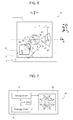
- Figure 7 illustrates an electronic device 40, which comprises the microelectromechanical gyroscope 30 described previously.
- the electronic device 40 can advantageously be used in a plurality of electronic systems, for example, in inertial navigation systems, in automotive systems, or in systems of a portable type, such as, for example: a PDA (Personal Digital Assistant); a portable computer; a cellphone; a digital audio player; a photographic camera or a camcorder; or further systems capable of processing, storing, transmitting, and receiving signals and information.
- PDA Personal Digital Assistant
- the electronic device 40 further comprises: a driving circuit 41, operatively coupled to the driving assembly 4 for imparting the rotary driving movement to the driving mass 3, and supplying biasing signals to the microelectromechanical structures (in a per-se known manner, which is not illustrated in detail herein); a read circuit 42, operatively coupled to the sensing electrodes 22, 23 of the first and second sensing masses, for detecting the amount of displacement of the same sensing masses and hence determining the angular velocities acting on the structure; and an electronic control unit 44, for example, of a microprocessor type, connected to the read circuit 42, and designed to supervise the general operation of the electronic device 40, for example, on the basis of the angular velocities detected and determined.
- the read circuit 42 includes the aforesaid electronic read interface, designed to appropriately combine the output signals corresponding to the individual first sensing masses, in order to increase the sensitivity of detection, as described previously.
- microelectromechanical gyroscope provided according to the present invention are clear from the foregoing description.
- the configuration of the sensing masses makes it possible to optimize exploitation of the area available for detection, increase the sensitivity of the sensor, and improve uniformity of the electrical characteristics and the robustness of the system to disturbance. More in general, this configuration allows to improve the characteristics and the electrical performance of the microelectromechanical gyroscope.
- the new configuration of the first sensing masses can advantageously be provided for a gyroscope that is only biaxial, i.e., not sensitive to yaw angular velocity (and hence without the second sensing masses 25a'-25b').
- the value of the angle ⁇ may differ from the value described, and be, for example, comprised between 40° and 50°.
- the angles of inclination of the two pairs of first sensing masses 16a'-16d' with respect to the first horizontal axis x may also not be the same, the two pairs of first sensing masses having in any case opposite inclination with respect to the first horizontal axis x, but in this case no longer be symmetrical with respect to the second horizontal axis y.
- the two diametric directions x 1 and x 2 may not be orthogonal to one another.
- the die pads 2d can extend in a different direction, for example, along the second horizontal axis y.
- the displacement of the sensing masses can be determined with a technique different from the capacitive one, for example, by detection of a magnetic force.
- twisting moment for causing oscillation of the driving mass with rotary movement can be generated in a different way, for example, by means of parallel-plate electrodes, or else by magnetic actuation.
- the configuration of some structural elements of the gyroscope may be different.
- the driving mass 3 may have a shape different from the circular one, such as a generally closed polygonal shape, as likewise the shape of the frame 2b of the die 2 can be different.
- a different configuration of the sensing electrodes associated to the sensing masses of the first and second types can be envisaged.
Abstract
Description
- The present invention relates to a microelectromechanical structure, in particular a biaxial or triaxial gyroscope, provided with a rotary driving movement and improved electrical characteristics, in particular in terms of sensitivity in the detection of angular velocities.
- As is known, micromachining techniques enable manufacturing of microelectromechanical structures or systems (MEMS) within layers of semiconductor material, which have been deposited (for example, a polycrystalline-silicon layer) or grown (for example, an epitaxial layer) on sacrificial layers, which are removed via chemical etching.
- Inertial sensors, accelerometers, and gyroscopes obtained with this technology are having an increasing success, for example, in the automotive field, in inertial navigation, or in the field of portable devices.
- In particular, known to the art are integrated gyroscopes made of semiconductor material obtained with MEMS technology. These gyroscopes operate on the basis of the theorem of relative accelerations, exploiting the Coriolis acceleration. When an angular velocity is applied to a mobile mass that moves at a linear velocity, the mobile mass "feels" an apparent force, referred to as "Coriolis force", which causes a displacement thereof in a direction perpendicular to the direction of the linear velocity and to the axis about which the angular velocity is applied. The mobile mass is supported via springs that enable a displacement thereof in the direction of the apparent force. On the basis of Hooke's law, the displacement is proportional to the apparent force, in such a way that from the displacement of the mobile mass it is possible to detect the Coriolis force and the value of the angular velocity that has generated it. The displacement of the mobile mass can, for example, be detected in a capacitive way by determining, in resonance conditions, the variations of capacitance caused by the movement of mobile electrodes, fixed with respect to the mobile mass and combfingered with fixed electrodes.
- The published European patent application
EP-A-1 832 841 and US patent applicationsUS 2009/0064780 andUS 2009/0100930 , filed by the applicant of the present application, disclose an integrated microelectromechanical sensor with rotary driving movement and sensitive to angular velocities of pitch, roll, and yaw about respective axes of detection. - This microelectromechanical sensor comprises a single driving mass, anchored to a substrate in a single central point, and actuated with rotary motion about an axis passing through the central point and orthogonal to the plane of the driving mass. The movement of rotation of the driving mass makes it possible to obtain in the plane of the mass two components of driving velocity orthogonal with respect to one another. Through openings are provided within the driving mass, and corresponding sensing masses are arranged in the through openings; the sensing masses are enclosed in the overall dimensions of the driving mass, are suspended with respect to the substrate, and are connected to the driving mass via flexible elements. Each sensing mass is fixed with respect to the driving mass during its rotary motion, and has a further degree of freedom of movement as a function of an external stress, in particular a Coriolis force, acting on the sensor. The flexible elements, thanks to their particular construction, enable the sensing masses to perform a rotary movement of detection about an axis belonging to the plane of the sensor, or alternatively a linear movement of detection along an axis belonging to the plane of the sensor, respectively, in response to a Coriolis acceleration acting in a direction perpendicular to the plane and to a Coriolis acceleration acting in a direction belonging to the plane. The movement of detection is in any case substantially decoupled from the movement of actuation of the driving mass. This microelectromechanical structure, in addition to being compact (in so far as it envisages a single driving mass enclosing in its overall dimensions a number of sensing masses), makes it possible to obtain with minor structural modifications, a uniaxial, biaxial, or triaxial gyroscope (and/or possibly an accelerometer, according to the electrical connections implemented), at the same time ensuring an excellent decoupling of the driving dynamics from the detection dynamics.
-
Figure 1 shows an exemplary embodiment of a triaxial microelectromechanical gyroscope, designated by 1, according to the teachings contained in the aforesaid patent applications. - The
gyroscope 1 is made in adie 2, comprising asubstrate 2a made of semiconductor material (for example, silicon), and aframe 2b defining inside it anopen region 2c; theopen region 2c overlies thesubstrate 2a, and is designed to house detection structures of the gyroscope 1 (as described in detail hereinafter). Theopen region 2c has a generally square or rectangular configuration in a horizontal plane (in what follows, plane of the sensor xy), defined by a first horizontal axis x and a second horizontal axis y, fixed with respect to thedie 2. Theframe 2b has sides that are substantially parallel to the horizontal axes x, y. Contactpads 2d (so-called "die pads") are arranged along a side of theframe 2b, aligned, for example, along the first horizontal axis x. In a way not illustrated, thedie pads 2d enable electrical contact from outside of the detection structures of thegyroscope 1. Thedie pads 2d have an axis of symmetry, in this case coinciding with the second horizontal axis y (orthogonal to their direction of alignment), and are arranged in equal number and in a specular way on opposite sides of the second horizontal axis y. - In particular, the first and second horizontal axes x, y correspond to a first axis of detection and to a second axis of detection of the gyroscope 1 (more precisely, to a pitch axis and to a roll axis), about which corresponding pitch and roll angular velocities
Ω x andΩ y are detected. - In detail, the
gyroscope 1 comprises a driving structure, housed within theopen region 2c and including a driving mass 3 and a driving assembly 4. - The driving mass 3 has a generally circular geometry with radial symmetry, with a substantially planar configuration having a main extension in the plane of the sensor xy, and a negligible dimension, with respect to the main extension, in a direction parallel to a vertical axis z, forming with the first and second horizontal axes x, y a set of three orthogonal axes, fixed with respect to the
die 2. For example, the driving mass 3 has in the plane of the sensor xy basically the shape of an annulus, and defines at the center an empty space 6, the center O of which coincides with the center of gravity and the center of symmetry of the entire structure. - The driving mass 3 is anchored to the
substrate 2a by means of afirst anchorage 7a set in an area corresponding to the center O, to which it is connected through firstelastic anchorage elements 8a. In the example, the firstelastic anchorage elements 8a depart, forming a cross, from the center O, parallel to the first and second horizontal axes x, y. The driving mass 3 is anchored to thesubstrate 2a by means offurther anchorages 7b, set on the outside of the same driving mass 3, to which it is connected by means of furtherelastic anchorage elements 8b. For example, the furtherelastic anchorage elements 8b are of the folded type, are four in number, and are set aligned in pairs along the first and second horizontal axes x, y; accordingly, thefurther anchorages 7b are arranged, in pairs, on opposite sides of the driving mass 3 with respect to the empty space 6, at the ends of a cross centered in the center O. The first and furtherelastic anchorage elements - The driving mass 3 has: a first pair of first through
openings openings through openings 9a-9b of the first pair are symmetrical with respect to the second horizontal axis y, and the throughopenings 9c-9d of the second pair are symmetrical with respect to the first horizontal axis x. Moreover, the driving mass 3 has a pair of second throughopenings Figure 1 in a direction inclined by 45° with respect to the first horizontal axis x or the second horizontal axis y), and having a main extension in the same radial direction. - The driving assembly 4 comprises a plurality of driven
arms 10, extending externally from the driving mass 3 in a radial direction and in such a way that they are set at equal angular distances apart, and a plurality of first and second drivingarms arms 10. Each drivenarm 10 carries a plurality offirst electrodes 13, extending perpendicular to, and on either side of, the same driven arm. In addition, each of the first and second drivingarms second electrodes arm 10 and are combfingered with the correspondingfirst electrodes 13. The first drivingarms 12a are arranged all on one and the same side of the respective drivenarms 10, and are biased all at one and the same first voltage. Likewise, the second drivingarms 12b are arranged all on the opposite side of the respective drivenarms 10, and are biased all at one and the same second voltage. A driving circuit (not illustrated) is connected to thesecond electrodes - The
gyroscope 1 further comprises a first pair of acceleration sensors with axis parallel to the vertical axis z, and in particular a first pair offirst sensing masses first sensing masses first sensing masses first portion 17, which is wider, and asecond portion 18, which is narrower (along the first horizontal axis x), these portions being connected by a connectingportion 19, which is shorter (in a direction parallel to the second horizontal axis y) than the first andsecond portions first portion 17. In greater detail, thefirst portion 17 has an outer side that is arc-shaped and concave, and radially-extending lateral sides, and thesecond portion 18 has an outer side that is arc-shaped and convex and radially-extending lateral sides, aligned along the lateral sides of thefirst portion 17. Each of thefirst sensing masses elements 20, extending from the connectingportion 19 to the driving mass 3, connecting thereto, parallel to the second horizontal axis y. The first elastic supportingelements 20 extend within recesses 21 provided on opposite sides of the correspondingfirst sensing mass elements 20 form torsional springs which are rigid in regard to the rotary motion of the driving mass 3 (so that thefirst sensing masses - The
gyroscope 1 further comprises a second pair of acceleration sensors with axis parallel to the vertical axis z, and in particular a second pair offirst sensing masses openings first sensing masses first sensing masses elements 20 extend parallel to the first horizontal axis x and enable rotation out of the plane of the sensor xy, about an axis of rotation parallel to the first horizontal axis x. - A pair of first and
second sensing electrodes second portions first sensing masses 16a-16d. The first andsecond sensing electrodes substrate 2a and having a substantially trapezoidal shape and dimensions substantially corresponding to those of thesecond portion 18. The first andsecond sensing electrodes second portions second portions second sensing electrodes connection pads 2d. - The
gyroscope 1 further comprises a pair ofsecond sensing masses openings second sensing masses openings substrate 2a, and are connected to the driving mass 3 via second elastic supportingelements 28. The second elastic supportingelements 28 depart, for example, from a point set approximately at the center of the minor sides of the second sensing masses, in the radial direction. In particular, the second elastic supportingelements 28 are rigid with respect to the motion of actuation of the driving mass 3 (in such a way that thesecond sensing masses second sensing masses prolongations 29 extending, for example, starting from a point set approximately at the centre of corresponding major sides, in a direction orthogonal to the radial direction. Theseprolongations 29 form sensing capacitors with plane and parallel faces with fixed electrodes anchored to the substrate, set facing, and parallel to, thesame prolongations 29. For example, from each major side of each second sensingmass respective prolongation 29, which faces, and is set between, two fixed electrodes. In a way similar to what has been described previously, the fixed electrodes set in a radially more external position with respect to the center O are defined as "first sensing electrodes 22", and the fixed electrodes set in a radially more internal position are defined as "second sensing electrodes 23". - In use, the
gyroscope 1 is able to operate as a triaxial gyroscope, and to detect a pitch angular velocity Ωx about the first horizontal axis x, a roll angular velocityΩ y about the second horizontal axis y, and a yaw angular velocityΩ z about the vertical axis z. - With reference also to
Figure 2 , the rotary movement of the driving mass 3 and of thefirst sensing masses 16a-16d about the axis of actuation can be represented by a driving-velocity vectorv a, tangential to the circumference describing the path thereof. In particular, the rotary motion about the first horizontal axis x or the second horizontal axis y with angular velocityΩ x,Ω y causes a Coriolis force (designated byF c) acting on the entire structure, proportional to the vector product between the angular velocityΩ x,Ω y and the driving velocityv a, and hence directed along the vertical axis z. On the entire structure, considered as a single rigid body, it is hence possible to identify a distribution of Coriolis forces, the value of which increases as the distance from the center O increases. The resultants of the Coriolis forceF C acting on thefirst sensing masses 16a-16d at the corresponding center of gravity G, cause rotation of the first sensing masses, which move out of the plane of the sensor xy, about an axis parallel to the first horizontal axis x or the second horizontal axis y and passing through the first elastic supportingelements 20. This movement is allowed by the torsion of the first elastic supportingelements 20. Instead, the configuration of the first and furtherelastic anchorage elements first sensing masses 16a-16d out of the plane of the sensor xy causes a differential capacitive variation of the sensing capacitors, the value of which is proportional to the angular velocityΩ x, Ωy, which can thus be determined, in a per-se known manner via an appropriate read circuit, operating according to a differential scheme. - In particular, since the reading scheme is differential, the configuration in pairs of the
first sensing masses 16a-16d enables automatic rejection of linear spurious accelerations along the vertical axis z. In addition, a rotation about the first horizontal axis x is not felt by the second pair offirst sensing masses F C is zero (since the vector product between the angular velocityΩ x and the corresponding driving velocityv a goes to zero). Likewise, the rotation about the second horizontal axis y is not felt for similar reasons by the first pair offirst sensing masses - With reference to
Figure 3 , an angular velocity Ωz to be detected, acting about the vertical axis z, generates a Coriolis forceF C on thesecond sensing masses Ω z, which can be determined, in a per-se known manner, via the read circuit, operating again according to a differential scheme. - Advantageously, the particular conformation of the
first sensing masses 16a-16d enables an increase in the sensitivity of the gyroscope 1 (as compared to the use of other geometries for the same first sensing masses). In particular, the corresponding center of gravity G is positioned at a distance from the first elastic supporting elements 20 (and the corresponding axis of rotation out of the plane of the sensor xy) that is greater than that of the center of gravity of any rectangular mass that can be inscribed in one and the same sector of the driving mass 3 and is supported by elastic supporting elements extending along the same axis of rotation. Consequently, it is possible to obtain a higher twisting moment, and hence a greater movement of rotation out of the plane of the sensor xy, and in this way obtain a higher sensitivity of the sensor. - In addition, the presence of the further
elastic anchorage elements 8b, located outside the driving mass 3, enables increase of the stiffness of the driving mass 3 in regard to the movements out of the plane of the sensor xy, and so an increase in the decoupling between the driving movement and the movements of detection. - Even though the described gyroscope represents a considerable improvement over other gyroscopes of a known type, the present applicant has found that it is not altogether optimized in respect of manufacturing simplicity, size reduction, efficiency in terms of electrical characteristics, and immunity to disturbance.
- The aim of the present invention is consequently to further improve the structure of the microelectromechanical gyroscope, in particular in regards to sensitivity to external stresses and robustness in regard to disturbance.
- Consequently, a microelectromechanical structure, as defined in
claim 1, is provided according to the present invention. - For a better understanding of the present invention, preferred embodiments thereof are now described purely by way of non-limiting example and with reference to the attached drawings, wherein:
-
Figure 1 shows a schematic top plan view of a microelectromechanical gyroscope, of a known type; -
Figures 2 and3 show, respectively, a schematic lateral cross-sectional view and a schematic top plan view, of parts of the gyroscope ofFigure 1 , in the presence of a Coriolis force; -
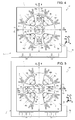
Figure 4 shows a schematic top plan view of a microelectromechanical gyroscope according to a first embodiment of the present invention; -
Figure 5 shows a schematic top plan view of a second embodiment of the microelectromechanical gyroscope; -
Figure 6 shows the schematic comparison between a portion of the microelectromechanical gyroscope, in a further variant embodiment thereof, and a corresponding portion of a sensor of a known type; and -
Figure 7 shows a simplified block diagram of an electronic device provided with the microelectromechanical gyroscope according to the invention. - As will be described in detail hereinafter, an aspect of the present invention envisages providing a microelectromechanical gyroscope having an arrangement of the sensing masses such as to enable an increase in the sensitivity of the sensor and in general an improvement of its electrical characteristics.
- As is shown in
Figure 4 , where the same reference numbers are used for indicating elements similar to others already described with reference toFigure 1 , the microelectromechanical gyroscope, here designated by 30, differs from thegyroscope 1 ofFigure 1 substantially on account of a different arrangement of the first sensing masses, here designated by 16a'-16d', and of the second sensing masses, here designated by 25a', 25b'. - In greater detail, the
first sensing masses 16a', 16b' of the first pair are aligned in a first diametric direction x1, inclined with respect to the first horizontal axis x of thedie 2 by an angle of inclination α (considered in a counterclockwise direction), the value of which is preferably 45°. Likewise, thefirst sensing masses 16c', 16d' of the second pair are aligned in a second diametric direction x2, substantially orthogonal to the first diametric direction x1, and inclined with respect to the first horizontal axis x by the same angle of inclination α (considered in this case in an opposite direction, namely clockwise). Thefirst sensing masses 16a'-16d' are consequently aligned in respective diametric directions, which are inclined with respect to the pitch and roll axes, about which the pitch angular velocityΩ x and the roll angular velocityΩ y are applied, and moreover inclined with respect to the sides of the die 2 (and to the horizontal axes x, y). - In addition, the
first sensing masses 16a', 16b' of the first pair are symmetrical tocorresponding sensing masses 16d', 16c' of the second pair, with respect to the axis of symmetry of thedie pads 2d (coinciding with the second horizontal axis y). - The
second sensing masses 25a'-25b' are arranged in the available space left free by thefirst sensing masses 16a'-16d', and are, for example, aligned along the second horizontal axis y (as illustrated inFigure 4 ). It may thus be noted that the arrangement of the first and second sensing masses inFigure 4 derives, as compared to the arrangement of the same masses ofFigure 1 , from a counterclockwise rotation through the angle of inclination α about the center O. - The present applicant has found that the aforesaid arrangement of the first and
second sensing masses 16a'-16d', 25a'-25b' makes it possible to achieve a series of advantages, amongst which a simplified connection of the corresponding first andsecond sensing electrodes die pads 2d. - In particular, in a per-se known manner (not described in detail herein), a first processing channel in the electronic read interface and corresponding electrical connections to the
connection pads 2d are associated to the first pair offirst sensing masses 16a'-16b', whilst associated to the second pair offirst sensing masses 16c'-16d' are, in the same electronic read interface, a second and distinct processing channel, and corresponding electrical connections to therespective connection pads 2d. - The present applicant has found that in the arrangement of a known type shown in
Figure 1 , the position of thefirst sensing masses 16a-16d with respect to theconnection pads 2d of thedie 2 shows a marked lack of uniformity (as do the corresponding electrical connections to thesame connection pads 2d). In fact, the two pairs offirst sensing masses 16a-16d are mutually positioned in an asymmetrical way with respect to the axis of symmetry of theconnection pads 2d, thus calling for a different design of the electrical connections for the two processing channels. Consequently, the reading performance referred to the two axes of detection (of pitch and roll) may be different, and possibly must be compensated for by the electronic read interface (which is consequently more complex). - Instead, the arrangement described in
Figure 4 for thefirst sensing masses 16a'-16d' with respect to theconnection pads 2d makes it possible to obtain a substantial symmetry of the electrical connections to theconnection pads 2d for the two processing channels (the two pairs of first sensing masses are in fact set in an altogether symmetrical way with respect to the axis of symmetry of theconnection pads 2d). The symmetry of the electrical connections enables, in a per-se known manner, considerable advantages to be obtained in terms of uniformity in the electrical characteristics (for example, in terms of active and parasitic capacitances, or leakage currents) and robustness to the spread of the parameters resulting from the manufacturing process. - Advantageously, the arrangement described enables an increase of the symmetry also of the electrical connections referred to the
second sensing masses 25a'- 25b', thus leading to an increase of uniformity in the electrical characteristics of the corresponding read electronics. In particular, the arrangement of thesecond sensing masses 25a'-25b' guarantees a substantial symmetry of the overall structure with respect to the axis of symmetry of theconnection pads 2d, thus further simplifying the design of the electrical connections. -
Figure 5 shows a variant embodiment of thegyroscope 30, which differs from the one shown inFigure 4 in so far as thesecond sensing masses 25a'-25b' are aligned along the first horizontal axis x, instead of along the second horizontal axis y. Also in this case, the same considerations made previously still apply. In particular, this configuration intuitively enables a further increase in the symmetry of the detection structure with respect to the axis of symmetry of thedie pads 2d. - The present applicant has found that the aforesaid arrangement of the first and
second sensing masses 16a'-16d', 25a'-25b' also allows to optimize exploitation of the space available in the gyroscope for detection of the angular velocity. - The area available for providing the detection structures, coinciding with the
open region 2c defined by theframe 2b of thedie 2, in fact usually has a square shape (as is shown inFigure 4 and inFigure 6 ) or a rectangular shape. The arrangement of thefirst sensing masses 16a'-16d' in directions inclined with respect to the sides of theframe 2b and to the horizontal axes x, y enables increase of the dimensions and maximization of the sensitivity of the first sensing masses, exploiting for detection the areas at a greater distance from the axis of rotation of actuation. - In greater detail, and as is shown in
Figure 6 , which represents in a simplified way just the area available (open region 2c) of thegyroscope 30 and a first sensing mass (for example, thefirst sensing mass 16a'), the conformation of thefirst sensing masses 16a'-16d' can in this case be modified so as to improve exploitation of the space available in a radial direction, until the internal edges of theframe 2b are approached. In a way not illustrated, also the conformation of the driving mass 3, within the overall dimensions of which the sensing masses are housed, is in this case modified. - In particular, represented with a solid line is a variant embodiment of the
first sensing mass 16a', having in this case a generally rhomboidal shape extending towards an internal edge of theframe 2b and its center of gravity G' located at an arm bc' from the first elastic supportingelements 20. In the sameFigure 6 , illustrated with a dashed line, purely to facilitate a comparison between the different solutions, is a first sensing mass of a traditional type (for example, thefirst sensing mass 16b ofFigure 1 ), having the shape, described previously, of a radial sector. Thefirst sensing mass 16b of a traditional type has its center of gravity G located at an arm bc from the respective first elastic supportingelements 20. Both of the first sensing masses illustrated are located at one and the same radial distance d between the respective first elastic supportingelements 20 and the center O. - This comparison highlights the fact that the arm bc of the traditional sensing mass has a value visibly smaller than that of the arm bc' that can be obtained in the new configuration. In particular, the increase of the distance of the center of gravity G' of the
first sensing masses 16a'-16d' from the center O enables an increase in the driving velocityv a felt by the same first sensing masses (given the same angle of rotation of the driving mass 3), and hence an increase in the Coriolis force Fc', given that this force is directly proportional to the driving velocityv a. In addition, since the Coriolis force Fc' is applied at a greater arm bc', the value of the resulting twisting moment increases. - In addition, this configuration allows to have available a greater surface for the
sensing electrodes - The present applicant has also found that the aforesaid arrangement of the first and
second sensing masses 16a'-16d', 25a'-25b' makes it possible to obtain, using an appropriate configuration of the electronic read interface, a further increase in the sensitivity of thegyroscope 30. - In detail, the
gyroscope 30, shown inFigures 4 and 5 , has the peculiarity of having the axes of detection in the plane of the sensor xy (coinciding with the first and second diametric directions x1, x2 of alignment of thefirst sensing masses 16a'-16d') inclined by the angle α with respect to the horizontal axes x and y about which the pitch angular velocityΩ x and the roll angular velocityΩ y act. - Instead of envisaging assembly of the
die 2 rotated by a corresponding angle α at the level of package or board, which would evidently make it possible to re-orient the axes of detection according to the original directions of pitch and roll (i.e., the horizontal axes x and y), a further aspect of the present invention envisages to suitably combine at the electronic read interface level the detection signals coming from thefirst sensing masses 16a'-16d'. In particular, the detection signals are combined so as to re-obtain, starting from the capacitive variations associated to the displacements of thefirst sensing masses 16a'-16d', voltage outputs corresponding to the original pitch and roll directions (i.e., to the horizontal axes x and y). - In detail, the case where the angular velocity to be detected about the first horizontal axis x or the second horizontal axis y has a unit value is considered for simplicity:

first sensing masses 16a'-16d' has a unit sensitivity S:
- Intuitively, in the case of a traditional configuration (for example, of the type illustrated in
Figure 1 , havingfirst sensing masses 16a-16d aligned along the horizontal axes x, y), the following voltage values would be obtained at output from the electronic read interface:
where Vout,x is the output voltage corresponding to the first pair offirst sensing masses 16a-16b aligned along the first horizontal axis x, and Vout,y is the output voltage corresponding to the second pair offirst sensing masses 16c-16d aligned along the second horizontal axis y (in the traditional solution). - In particular, as described previously, an angular velocity (of pitch or roll) about one of the horizontal axes x, y would determine a capacitive unbalancing of a single pair of
first sensing masses 16a-16d (in particular the pair aligned about the same horizontal axis). - Instead, in the new configuration illustrated in
Figure 4 or inFigure 5 , an angular velocity (of pitch or roll) about one of the horizontal axes x, y determines a capacitive unbalancing of both of the pairs offirst sensing masses 16a'-16b' and 16c'-16d', in so far as they are sensitive to the components of the angular velocities of pitch and roll along the diametric directions X1 and X2, and these components have a non-zero value for both of the pairs. Given the same geometry and distance from the center O of thefirst sensing masses 16a'-16d', in this case the following total output voltages for the horizontal axes x, y are obtained:
where Vout,x1 and Vout,x2 are the output voltages corresponding to the first pair and, respectively, to the second pair offirst sensing masses 16a'-16d', aligned, respectively, in the first and second diametric directions X1, X2. - Consequently, although the capacitive unbalancing of the single first sensing masses referred to a given angular velocity is smaller by a
factor 
gyroscope 30 by afactor 
-
Figure 7 illustrates anelectronic device 40, which comprises themicroelectromechanical gyroscope 30 described previously. Theelectronic device 40 can advantageously be used in a plurality of electronic systems, for example, in inertial navigation systems, in automotive systems, or in systems of a portable type, such as, for example: a PDA (Personal Digital Assistant); a portable computer; a cellphone; a digital audio player; a photographic camera or a camcorder; or further systems capable of processing, storing, transmitting, and receiving signals and information. - The
electronic device 40 further comprises: a drivingcircuit 41, operatively coupled to the driving assembly 4 for imparting the rotary driving movement to the driving mass 3, and supplying biasing signals to the microelectromechanical structures (in a per-se known manner, which is not illustrated in detail herein); aread circuit 42, operatively coupled to thesensing electrodes electronic control unit 44, for example, of a microprocessor type, connected to theread circuit 42, and designed to supervise the general operation of theelectronic device 40, for example, on the basis of the angular velocities detected and determined. In particular, theread circuit 42 includes the aforesaid electronic read interface, designed to appropriately combine the output signals corresponding to the individual first sensing masses, in order to increase the sensitivity of detection, as described previously. - The advantages of the microelectromechanical gyroscope provided according to the present invention are clear from the foregoing description.
- In any case, it is once again emphasized that the configuration of the sensing masses makes it possible to optimize exploitation of the area available for detection, increase the sensitivity of the sensor, and improve uniformity of the electrical characteristics and the robustness of the system to disturbance. More in general, this configuration allows to improve the characteristics and the electrical performance of the microelectromechanical gyroscope.
- Finally, it is clear that modifications and variations can be made to what has been described and illustrated herein, without thereby departing from the scope of the present invention, as defined in the annexed claims.
- In particular, it is evident that the new configuration of the first sensing masses can advantageously be provided for a gyroscope that is only biaxial, i.e., not sensitive to yaw angular velocity (and hence without the
second sensing masses 25a'-25b'). - For specific design requirements, the value of the angle α may differ from the value described, and be, for example, comprised between 40° and 50°. The angles of inclination of the two pairs of
first sensing masses 16a'-16d' with respect to the first horizontal axis x may also not be the same, the two pairs of first sensing masses having in any case opposite inclination with respect to the first horizontal axis x, but in this case no longer be symmetrical with respect to the second horizontal axis y. In addition, the two diametric directions x1 and x2 may not be orthogonal to one another. - In addition, the
die pads 2d can extend in a different direction, for example, along the second horizontal axis y. In a per-se known manner, the displacement of the sensing masses can be determined with a technique different from the capacitive one, for example, by detection of a magnetic force. - In addition, the twisting moment for causing oscillation of the driving mass with rotary movement can be generated in a different way, for example, by means of parallel-plate electrodes, or else by magnetic actuation.
- More in general, it is evident that the configuration of some structural elements of the gyroscope may be different. For example, the driving mass 3 may have a shape different from the circular one, such as a generally closed polygonal shape, as likewise the shape of the
frame 2b of thedie 2 can be different. Alternatively, it is possible to envisage a different arrangement of the first elastic anchorage elements of the driving mass 3 (which must be in any case able to perform decoupling of the driving mass from the motion of detection), or of the second elastic supporting elements 28 (which must be in any case such as to enable the radial movement of the sensing masses of the second type). In addition, a different configuration of the sensing electrodes associated to the sensing masses of the first and second types can be envisaged.
Claims (15)
- An integrated microelectromechanical structure (30), characterized by comprising:a die (2), including a substrate (2a) and a frame (2b), which defines inside it a detection region (2c) and has a first side extending along a first horizontal axis (x);a driving mass (3), anchored to said substrate (2) via elastic anchorage elements (8a, 8b), set in said detection region (2c), and designed to be rotated in a plane (xy) with a movement of actuation about a vertical axis (z);a first pair (16a', 16b') and a second pair (16c', 16d') of first sensing masses, suspended inside, and coupled to, said driving mass (3) via respective elastic supporting elements (20) so as to be fixed with respect thereto in said movement of actuation and perform a detection movement of rotation out of said plane (xy) in response to a first angular velocity (
Ω x); the first sensing masses of said first pair (16a', 16b') and the first sensing masses of said second pair (16c', 16d') being aligned in respective directions (x1, x2), having non-zero inclinations of opposite sign with respect to said first horizontal axis. - The structure according to claim 1, wherein said first sensing masses of said first pair (16a', 16b') are aligned in a first direction (x1) inclined with respect to said first horizontal axis (x) by an angle (α), and said first sensing masses of said second pair (16c', 16d') are aligned in a second direction (x2) inclined by the same angle (α), on an opposite side with respect to said first horizontal axis (x).
- The structure according to claim 2, wherein said angle (α) has a value substantially equal to 45°, and said first direction (x1) and said second direction (x2) are substantially orthogonal to one another.
- The structure according to any of the preceding claims, further comprising a plurality of die pads (2d) extending along said first side of said frame (2b) in a symmetrical way with respect to a second horizontal axis (y); wherein each of said first sensing masses of said first pair (16a', 16b') is arranged symmetrically to a corresponding one of said first sensing masses of said second pair (16d', 16c') with respect to said second horizontal axis (y).
- The structure according to claim 4, wherein to each one of said first sensing masses of said first pair (16a', 16b') and of said second pair (16c', 16d') are associated sensing electrodes (22, 23) designed to form sensing capacitors, and electrical connections between said respective sensing electrodes (22, 23) and respective ones of said die pads (2d); wherein electrical connections associated to said first sensing masses of said first pair (16a', 16b') are set symmetrically to corresponding electrical connections associated to said first sensing masses of said second pair (16c', 16d'), with respect to said second horizontal axis (y).
- The structure according to any of the preceding claims, wherein said frame (2b) has a second side extending along a second horizontal axis (y) and defining an edge with said first side; wherein at least one first sensing mass (16a') of said first and second pairs is shaped so as to extend as far as into the proximity of said edge, along a respective one between said first direction (x1) and said second direction (x2).
- The structure according to claim 6, wherein said at least one first sensing mass (16a') has a generally rhomboidal shape, elongated along said respective one between said first direction (x1) and said second direction (x2).
- The structure according to any of the preceding claims, wherein said first angular velocity (
Ω x,Ω y) is applied in use about said first horizontal axis (x), coinciding with a first axis of detection of said structure (30). - The structure according to claim 8, of a biaxial type, wherein said first sensing masses of said first pair (16a', 16b') and second pair (16c', 16d') are also designed to perform said detection movement of rotation out of said plane (xy) in response to a second angular velocity (
Ω y), applied in use about a second horizontal axis (y), orthogonal to said first horizontal axis (x) and coinciding with a second axis of detection of said structure (30). - The structure according to claim 9, of a triaxial type, further comprising a pair of second sensing masses (25a', 25b'), suspended inside, and coupled to, said driving mass (3) via respective elastic supporting elements (28) so as to be fixed with respect thereto in said movement of actuation and so as to perform a linear movement of detection in said plane (xy) in response to a further angular velocity (
Ω z) applied in use about said vertical axis (z); wherein said second sensing masses (25a', 25b') are aligned along one between said first horizontal axis (x) and second horizontal axis (y). - The structure according to any of the preceding claims, wherein said frame (2b) has a generally square or rectangular shape, with first sides parallel to said first horizontal axis (x) and second sides parallel to a second horizontal axis (y), orthogonal to said first horizontal axis (x).
- The structure according to any of the preceding claims, wherein said driving mass (3) defines at the center an empty space (6) and is anchored to said substrate (2) at a first anchorage (7a) set at the center (O) of said empty space (6) via first elastic anchorage elements (8a) extending inside said empty space (6), and also at further anchorages (7b) set on the outside of said driving mass (3), via further elastic anchorage elements (8b); wherein said elastic supporting elements (6) and said first (8a) and further (8b) elastic anchorage elements are configured in such a way that said driving mass (3) is decoupled from said first sensing masses (16a'-16d') in said detection movement of rotation out of said plane (xy).
- The structure according to any of the preceding claims, wherein said first sensing masses (16a'-16d') have a conformation such as to have a center of gravity (G') located at a distance from the axis of rotation of said detection movement of rotation out of said plane (xy) that is greater than that of the center of gravity (G) of any sensing mass having a rectangular shape that can be inscribed within said driving mass (3) and is supported by respective elastic supporting elements for rotation about said axis of rotation.
- An electronic device (40) comprising an integrated microelectromechanical structure (30) according to any one of the preceding claims, and a read stage (42), operatively coupled to said structure (30).
- The device according to claim 14, wherein said read stage (42) is connected to said die pads (2d) for receiving electrical signals from each of said first sensing masses (16a'-16d'), and is configured so as to combine said electrical signals and generate a first electrical output quantity and a second electrical output quantity (Vout,x, Vout,y), which are a function, respectively, of a first angular velocity (
Ω x) applied about said first horizontal axis (x) and a second angular velocity (Ω y) applied about a second horizontal axis (y), orthogonal to said first horizontal axis (x).
Applications Claiming Priority (1)
| Application Number | Priority Date | Filing Date | Title |
|---|---|---|---|
| ITTO2008A000876A IT1391972B1 (en) | 2008-11-26 | 2008-11-26 | MICROELETTROMECHANICAL GYROSCOPE WITH ROTARY DRIVE MOVEMENT AND IMPROVED ELECTRICAL CHARACTERISTICS |
Publications (2)
| Publication Number | Publication Date |
|---|---|
| EP2192382A1 true EP2192382A1 (en) | 2010-06-02 |
| EP2192382B1 EP2192382B1 (en) | 2012-08-29 |
Family
ID=41170162
Family Applications (1)
| Application Number | Title | Priority Date | Filing Date |
|---|---|---|---|
| EP09177114A Active EP2192382B1 (en) | 2008-11-26 | 2009-11-25 | Microelectromechanical gyroscope with rotary driving motion and improved electrical properties |
Country Status (5)
| Country | Link |
|---|---|
| US (3) | US8413506B2 (en) |
| EP (1) | EP2192382B1 (en) |
| JP (1) | JP5453065B2 (en) |
| CN (1) | CN101920927B (en) |
| IT (1) | IT1391972B1 (en) |
Cited By (1)
| Publication number | Priority date | Publication date | Assignee | Title |
|---|---|---|---|---|
| FR2985029A1 (en) * | 2011-12-22 | 2013-06-28 | Commissariat Energie Atomique | MICRO / NANO MULTIMETERIAL INERTIAL SENSOR DEVICE FOR MOVEMENTS |
Families Citing this family (65)
| Publication number | Priority date | Publication date | Assignee | Title |
|---|---|---|---|---|
| US8042394B2 (en) * | 2007-09-11 | 2011-10-25 | Stmicroelectronics S.R.L. | High sensitivity microelectromechanical sensor with rotary driving motion |
| ITTO20090489A1 (en) * | 2008-11-26 | 2010-12-27 | St Microelectronics Srl | READING CIRCUIT FOR A MULTI-AXIS MEMS GYROSCOPE WITH DETECTED DETECTION DIRECTIONS COMPARED TO THE REFERENCE AXES, AND CORRESPONDING MEMS MULTI-AXIS GIROSCOPE |
| IT1391973B1 (en) | 2008-11-26 | 2012-02-02 | St Microelectronics Rousset | MONO OR BIASSIAL MICROELECTROMECHANICAL GYROSCOPE WITH INCREASED SENSITIVITY TO THE ANGULAR SPEED DETECTION |
| IT1391972B1 (en) | 2008-11-26 | 2012-02-02 | St Microelectronics Rousset | MICROELETTROMECHANICAL GYROSCOPE WITH ROTARY DRIVE MOVEMENT AND IMPROVED ELECTRICAL CHARACTERISTICS |
| IT1392741B1 (en) | 2008-12-23 | 2012-03-16 | St Microelectronics Rousset | MICROELETTROMECHANICAL GYROSCOPE WITH IMPROVED REJECTION OF ACCELERATION DISORDERS |
| JP2010190706A (en) * | 2009-02-18 | 2010-09-02 | Panasonic Corp | Inertial force sensor |
| IT1394007B1 (en) | 2009-05-11 | 2012-05-17 | St Microelectronics Rousset | MICROELETTROMECANICAL STRUCTURE WITH IMPROVED REJECTION OF ACCELERATION DISORDERS |
| US9097524B2 (en) | 2009-09-11 | 2015-08-04 | Invensense, Inc. | MEMS device with improved spring system |
| US8534127B2 (en) | 2009-09-11 | 2013-09-17 | Invensense, Inc. | Extension-mode angular velocity sensor |
| ITTO20091042A1 (en) | 2009-12-24 | 2011-06-25 | St Microelectronics Srl | MICROELETTROMECHANICAL INTEGRATED GYROSCOPE WITH IMPROVED DRIVE STRUCTURE |
| DE112011103124T5 (en) | 2010-09-18 | 2013-12-19 | Fairchild Semiconductor Corporation | Bearing for reducing quadrature for resonant micromechanical devices |
| EP2616771B8 (en) | 2010-09-18 | 2018-12-19 | Fairchild Semiconductor Corporation | Micromachined monolithic 6-axis inertial sensor |
| CN103238075B (en) | 2010-09-18 | 2015-11-25 | 快捷半导体公司 | There is the micromechanics triaxial accelerometer of single mass |
| CN103221332B (en) | 2010-09-18 | 2015-11-25 | 快捷半导体公司 | Reduce the encapsulation of the stress on MEMS |
| US9278845B2 (en) | 2010-09-18 | 2016-03-08 | Fairchild Semiconductor Corporation | MEMS multi-axis gyroscope Z-axis electrode structure |
| US10065851B2 (en) | 2010-09-20 | 2018-09-04 | Fairchild Semiconductor Corporation | Microelectromechanical pressure sensor including reference capacitor |
| JP5652112B2 (en) * | 2010-10-18 | 2015-01-14 | セイコーエプソン株式会社 | Physical quantity sensor and electronic equipment |
| JP5652117B2 (en) * | 2010-10-21 | 2015-01-14 | セイコーエプソン株式会社 | Physical quantity sensor and electronic equipment |
| US9003882B1 (en) * | 2010-11-03 | 2015-04-14 | Georgia Tech Research Corporation | Vibratory tuning fork based six-degrees of freedom inertial measurement MEMS device |
| FR2974895B1 (en) | 2011-05-02 | 2013-06-28 | Commissariat Energie Atomique | GYROMETER WITH REDUCED CAPACITY PARASITES |
| JP5287939B2 (en) | 2011-06-28 | 2013-09-11 | 株式会社デンソー | Angular velocity sensor |
| ITTO20110806A1 (en) | 2011-09-12 | 2013-03-13 | St Microelectronics Srl | MICROELETTROMECANICAL DEVICE INTEGRATING A GYROSCOPE AND AN ACCELEROMETER |
| US10914584B2 (en) | 2011-09-16 | 2021-02-09 | Invensense, Inc. | Drive and sense balanced, semi-coupled 3-axis gyroscope |
| US8448513B2 (en) | 2011-10-05 | 2013-05-28 | Freescale Semiconductor, Inc. | Rotary disk gyroscope |
| DE102011057081A1 (en) * | 2011-12-28 | 2013-07-04 | Maxim Integrated Products, Inc. | Micro rotation rate sensor and method for operating a micro yaw rate sensor |
| US8978475B2 (en) | 2012-02-01 | 2015-03-17 | Fairchild Semiconductor Corporation | MEMS proof mass with split z-axis portions |
| JP6338813B2 (en) * | 2012-04-03 | 2018-06-06 | セイコーエプソン株式会社 | Gyro sensor and electronic device using the same |
| US9488693B2 (en) | 2012-04-04 | 2016-11-08 | Fairchild Semiconductor Corporation | Self test of MEMS accelerometer with ASICS integrated capacitors |
| EP2648334B1 (en) | 2012-04-05 | 2020-06-10 | Fairchild Semiconductor Corporation | Mems device front-end charge amplifier |
| EP2647955B8 (en) | 2012-04-05 | 2018-12-19 | Fairchild Semiconductor Corporation | MEMS device quadrature phase shift cancellation |
| EP2647952B1 (en) | 2012-04-05 | 2017-11-15 | Fairchild Semiconductor Corporation | Mems device automatic-gain control loop for mechanical amplitude drive |
| US9625272B2 (en) | 2012-04-12 | 2017-04-18 | Fairchild Semiconductor Corporation | MEMS quadrature cancellation and signal demodulation |
| JP6191151B2 (en) * | 2012-05-29 | 2017-09-06 | 株式会社デンソー | Physical quantity sensor |
| EP2865990A4 (en) * | 2012-06-22 | 2016-03-16 | Nat Inst Of Advanced Ind Scien | Device for measuring rotation angle acceleration |
| DE102013014881B4 (en) | 2012-09-12 | 2023-05-04 | Fairchild Semiconductor Corporation | Enhanced silicon via with multi-material fill |
| KR101961478B1 (en) | 2012-09-19 | 2019-03-22 | 엘지이노텍 주식회사 | Camera Module |
| US9547095B2 (en) * | 2012-12-19 | 2017-01-17 | Westerngeco L.L.C. | MEMS-based rotation sensor for seismic applications and sensor units having same |
| EP3019442A4 (en) | 2013-07-08 | 2017-01-25 | Motion Engine Inc. | Mems device and method of manufacturing |
| WO2015042700A1 (en) | 2013-09-24 | 2015-04-02 | Motion Engine Inc. | Mems components and method of wafer-level manufacturing thereof |
| EP3028007A4 (en) | 2013-08-02 | 2017-07-12 | Motion Engine Inc. | Mems motion sensor and method of manufacturing |
| US9404747B2 (en) | 2013-10-30 | 2016-08-02 | Stmicroelectroncs S.R.L. | Microelectromechanical gyroscope with compensation of quadrature error drift |
| JP6590812B2 (en) | 2014-01-09 | 2019-10-16 | モーション・エンジン・インコーポレーテッド | Integrated MEMS system |
| US20170030788A1 (en) | 2014-04-10 | 2017-02-02 | Motion Engine Inc. | Mems pressure sensor |
| CN105043370B (en) * | 2014-04-29 | 2019-01-22 | 财团法人工业技术研究院 | Micro-motor device with fulcrum element |
| US9726493B2 (en) * | 2014-05-16 | 2017-08-08 | Hanking Electronics, Ltd. | Shock-robust integrated multi-axis MEMS gyroscope |
| EP2955480B1 (en) * | 2014-05-21 | 2023-09-06 | InvenSense, Inc. | Mems sensor with decoupled drive system |
| US11674803B2 (en) | 2014-06-02 | 2023-06-13 | Motion Engine, Inc. | Multi-mass MEMS motion sensor |
| US11287486B2 (en) | 2014-12-09 | 2022-03-29 | Motion Engine, Inc. | 3D MEMS magnetometer and associated methods |
| CA3220839A1 (en) | 2015-01-15 | 2016-07-21 | Motion Engine Inc. | 3d mems device with hermetic cavity |
| FI127202B (en) * | 2015-04-16 | 2018-01-31 | Murata Manufacturing Co | Triaxate gyroscope |
| DE102015211387A1 (en) * | 2015-06-19 | 2016-12-22 | Robert Bosch Gmbh | Three-axis spin sensor |
| ITUA20161498A1 (en) * | 2016-03-09 | 2017-09-09 | St Microelectronics Srl | MICROMECHANICAL DETECTION STRUCTURE OF A MEMS SENSOR DEVICE, IN PARTICULAR OF A MEMS GYRO, WITH IMPROVED DRIVE CHARACTERISTICS |
| ITUA20162172A1 (en) * | 2016-03-31 | 2017-10-01 | St Microelectronics Srl | ACCELEROMETRIC SENSOR MADE IN MEMS TECHNOLOGY WITH HIGH ACCURACY AND REDUCED SENSITIVITY TOWARDS TEMPERATURE AND AGING |
| US10371521B2 (en) | 2016-05-26 | 2019-08-06 | Honeywell International Inc. | Systems and methods for a four-mass vibrating MEMS structure |
| US10696541B2 (en) | 2016-05-26 | 2020-06-30 | Honeywell International Inc. | Systems and methods for bias suppression in a non-degenerate MEMS sensor |
| US10697994B2 (en) | 2017-02-22 | 2020-06-30 | Semiconductor Components Industries, Llc | Accelerometer techniques to compensate package stress |
| CN107796383B (en) * | 2017-10-17 | 2021-03-23 | 西北工业大学 | Chip-level rotation modulation type MEMS silicon micromechanical gyroscope |
| EP3671118B1 (en) | 2018-12-19 | 2021-08-25 | Murata Manufacturing Co., Ltd. | Vibration-robust multiaxis gyroscope |
| EP3671116B1 (en) * | 2018-12-19 | 2021-11-17 | Murata Manufacturing Co., Ltd. | Synchronized multi-axis gyroscope |
| US11725941B2 (en) * | 2019-01-08 | 2023-08-15 | Panasonic Intellectual Property Management Co., Ltd. | Sensing device |
| WO2020258177A1 (en) * | 2019-06-27 | 2020-12-30 | 瑞声声学科技(深圳)有限公司 | Differential resonator and mems sensor |
| JP7188311B2 (en) | 2019-07-31 | 2022-12-13 | セイコーエプソン株式会社 | Gyro sensors, electronic devices, and mobile objects |
| CN110779510B (en) * | 2019-11-14 | 2021-07-13 | 无锡莱斯能特科技有限公司 | Three-axis MEMS gyroscope |
| DE102020205369A1 (en) * | 2020-04-28 | 2021-10-28 | Robert Bosch Gesellschaft mit beschränkter Haftung | Micromechanical component for a yaw rate sensor and a corresponding manufacturing process |
| US11525680B2 (en) * | 2021-02-17 | 2022-12-13 | Nxp Usa, Inc. | Angular rate sensor with centrally positioned coupling structures |
Citations (5)
| Publication number | Priority date | Publication date | Assignee | Title |
|---|---|---|---|---|
| US20020189351A1 (en) * | 2001-06-14 | 2002-12-19 | Reeds John W. | Angular rate sensor having a sense element constrained to motion about a single axis and flexibly attached to a rotary drive mass |
| US20060112764A1 (en) * | 2004-12-01 | 2006-06-01 | Denso Corporation | Angular velocity detector having inertial mass oscillating in rotational direction |
| EP1832841A1 (en) | 2006-03-10 | 2007-09-12 | STMicroelectronics S.r.l. | Microelectromechanical integrated sensor structure with rotary driving motion |
| DE102006046772A1 (en) * | 2006-09-29 | 2008-04-03 | Siemens Ag | Rotating rate measuring arrangement, has capacitive units formed by fixed electrodes and by other electrodes that are connected with fixed connection, where exciting voltages are supplied to fixed electrodes of capacitive units |
| US20090064780A1 (en) | 2007-09-11 | 2009-03-12 | Stmicroelectronics S.R.L. | Microelectromechanical sensor with improved mechanical decoupling of sensing and driving modes |
Family Cites Families (82)
| Publication number | Priority date | Publication date | Assignee | Title |
|---|---|---|---|---|
| US572936A (en) * | 1896-12-08 | John thomas waters and guy clopton | ||
| US4159125A (en) | 1977-11-04 | 1979-06-26 | General Motors Corporation | Uncoupled strut suspension system |
| US4744248A (en) | 1985-07-25 | 1988-05-17 | Litton Systems, Inc. | Vibrating accelerometer-multisensor |
| JPS6293668A (en) | 1985-10-21 | 1987-04-30 | Hitachi Ltd | Angular speed/acceleration detector |
| US5205171A (en) | 1991-01-11 | 1993-04-27 | Northrop Corporation | Miniature silicon accelerometer and method |
| US5447068A (en) | 1994-03-31 | 1995-09-05 | Ford Motor Company | Digital capacitive accelerometer |
| DE4414237A1 (en) * | 1994-04-23 | 1995-10-26 | Bosch Gmbh Robert | Micromechanical vibrator of an oscillation gyrometer |
| DE19530007C2 (en) | 1995-08-16 | 1998-11-26 | Bosch Gmbh Robert | Yaw rate sensor |
| US6250156B1 (en) * | 1996-05-31 | 2001-06-26 | The Regents Of The University Of California | Dual-mass micromachined vibratory rate gyroscope |
| DE19641284C1 (en) * | 1996-10-07 | 1998-05-20 | Inst Mikro Und Informationstec | Rotation rate sensor with decoupled orthogonal primary and secondary vibrations |
| US6230563B1 (en) * | 1998-06-09 | 2001-05-15 | Integrated Micro Instruments, Inc. | Dual-mass vibratory rate gyroscope with suppressed translational acceleration response and quadrature-error correction capability |
| JP3796991B2 (en) | 1998-12-10 | 2006-07-12 | 株式会社デンソー | Angular velocity sensor |
| DE19938206A1 (en) * | 1999-08-12 | 2001-02-15 | Bosch Gmbh Robert | Micro-mechanical rotational acceleration sensor has an oscillating mass fixed at its center with an array of differential measurement capacitors for determination of acceleration directly rather than using time differentiation |
| JP3589182B2 (en) | 2000-07-07 | 2004-11-17 | 株式会社村田製作所 | External force measuring device |
| DE10108196A1 (en) * | 2001-02-21 | 2002-10-24 | Bosch Gmbh Robert | Yaw rate sensor |
| US6928872B2 (en) | 2001-04-27 | 2005-08-16 | Stmicroelectronics S.R.L. | Integrated gyroscope of semiconductor material with at least one sensitive axis in the sensor plane |
| EP1253399B1 (en) * | 2001-04-27 | 2006-06-21 | STMicroelectronics S.r.l. | Integrated gyroscope of semiconductor material |
| US6535800B2 (en) * | 2001-05-29 | 2003-03-18 | Delphi Technologies, Inc. | Vehicle rollover sensing using angular rate sensors |
| US6513380B2 (en) * | 2001-06-19 | 2003-02-04 | Microsensors, Inc. | MEMS sensor with single central anchor and motion-limiting connection geometry |
| US6722197B2 (en) * | 2001-06-19 | 2004-04-20 | Honeywell International Inc. | Coupled micromachined structure |
| JP3870895B2 (en) | 2002-01-10 | 2007-01-24 | 株式会社村田製作所 | Angular velocity sensor |
| US6725719B2 (en) | 2002-04-17 | 2004-04-27 | Milli Sensor Systems And Actuators, Inc. | MEMS-integrated inertial measurement units on a common substrate |
| FI119159B (en) | 2003-02-11 | 2008-08-15 | Vti Technologies Oy | Capacitive accelerator sensor construction |
| US6845665B2 (en) | 2003-04-28 | 2005-01-25 | Analog Devices, Inc. | Micro-machined multi-sensor providing 2-axes of acceleration sensing and 1-axis of angular rate sensing |
| US6837107B2 (en) * | 2003-04-28 | 2005-01-04 | Analog Devices, Inc. | Micro-machined multi-sensor providing 1-axis of acceleration sensing and 2-axes of angular rate sensing |
| US6848304B2 (en) * | 2003-04-28 | 2005-02-01 | Analog Devices, Inc. | Six degree-of-freedom micro-machined multi-sensor |
| FR2858853B1 (en) | 2003-08-13 | 2006-01-13 | Sercel Rech Const Elect | ACCELEROMETER WITH REDUCED PARASITE VIBRATION BY IMPROVED ELECTRODE FORM |
| FR2859528B1 (en) * | 2003-09-09 | 2006-01-06 | Thales Sa | MICRO-FACTORY GYROMETER WITH DOUBLE DIAPASON AND DETECTION IN PLATE PLATE |
| JP2005241500A (en) | 2004-02-27 | 2005-09-08 | Mitsubishi Electric Corp | Angular velocity sensor |
| US7287428B2 (en) * | 2004-04-14 | 2007-10-30 | Analog Devices, Inc. | Inertial sensor with a linear array of sensor elements |
| KR100652952B1 (en) | 2004-07-19 | 2006-12-06 | 삼성전자주식회사 | The MEMS gyroscope with coupling spring |
| EP1624286B1 (en) * | 2004-08-03 | 2017-10-04 | STMicroelectronics Srl | Micro-electro-mechanical sensor with force feedback loop |
| EP1626283B1 (en) * | 2004-08-13 | 2011-03-23 | STMicroelectronics Srl | Micro-electromechanical structure, in particular accelerometer, with improved insensitivity to thermomechanical stresses |
| US20080276706A1 (en) * | 2004-09-27 | 2008-11-13 | Conti Temic Microelectronic Gmbh | Rotation Speed Sensor |
| SE528404C2 (en) | 2004-10-20 | 2006-11-07 | Imego Ab | The sensor arrangement |
| US7155976B2 (en) * | 2005-01-05 | 2007-01-02 | Industrial Technology Research Institute | Rotation sensing apparatus and method for manufacturing the same |
| US7240552B2 (en) * | 2005-06-06 | 2007-07-10 | Bei Technologies, Inc. | Torsional rate sensor with momentum balance and mode decoupling |
| JP2007071677A (en) * | 2005-09-07 | 2007-03-22 | Hitachi Ltd | Combined sensor and manufacturing method therefor |
| US7454246B2 (en) * | 2005-09-08 | 2008-11-18 | Massachusetts Eye & Ear Infirmary | Sensor signal alignment |
| JP4887034B2 (en) * | 2005-12-05 | 2012-02-29 | 日立オートモティブシステムズ株式会社 | Inertial sensor |
| US8113050B2 (en) | 2006-01-25 | 2012-02-14 | The Regents Of The University Of California | Robust six degree-of-freedom micromachined gyroscope with anti-phase drive scheme and method of operation of the same |
| DE102007012163A1 (en) | 2006-03-10 | 2007-10-25 | Continental Teves Ag & Co. Ohg | Rotational speed sensor e.g. micro-electro mechanical system, for use in e.g. electronic stability program control system, has torsion spring permitting torsion deflections of seismic masses, and base units coupled by coupling bar |
| JP4687577B2 (en) | 2006-06-16 | 2011-05-25 | ソニー株式会社 | Inertial sensor |
| US7461552B2 (en) * | 2006-10-23 | 2008-12-09 | Custom Sensors & Technologies, Inc. | Dual axis rate sensor |
| JP2008129088A (en) * | 2006-11-16 | 2008-06-05 | Eastman Kodak Co | Method for eliminating error of camera equipped with angular velocity detection system |
| US7934423B2 (en) | 2007-12-10 | 2011-05-03 | Invensense, Inc. | Vertically integrated 3-axis MEMS angular accelerometer with integrated electronics |
| US8020441B2 (en) | 2008-02-05 | 2011-09-20 | Invensense, Inc. | Dual mode sensing for vibratory gyroscope |
| US8250921B2 (en) | 2007-07-06 | 2012-08-28 | Invensense, Inc. | Integrated motion processing unit (MPU) with MEMS inertial sensing and embedded digital electronics |
| EP1962054B1 (en) * | 2007-02-13 | 2011-07-20 | STMicroelectronics Srl | Microelectromechanical gyroscope with open loop reading device and control method of a microelectromechanical gyroscope |
| US7950281B2 (en) | 2007-02-28 | 2011-05-31 | Infineon Technologies Ag | Sensor and method for sensing linear acceleration and angular velocity |
| DE102007030119A1 (en) * | 2007-06-29 | 2009-01-02 | Litef Gmbh | Coriolis |
| KR100885416B1 (en) | 2007-07-19 | 2009-02-24 | 건국대학교 산학협력단 | System for operating implementation accelerometer and rate gyroscope |
| DE102007035806B4 (en) | 2007-07-31 | 2011-03-17 | Sensordynamics Ag | Micromechanical rotation rate sensor |
| DE102007057042A1 (en) * | 2007-09-10 | 2009-03-12 | Continental Teves Ag & Co. Ohg | Micromechanical rotation rate sensor with coupling bars and suspension elements for quadrature suppression |
| GB0720412D0 (en) | 2007-10-18 | 2007-11-28 | Melexis Nv | Combined mems accelerometer and gyroscope |
| DE102007054505B4 (en) | 2007-11-15 | 2016-12-22 | Robert Bosch Gmbh | Yaw rate sensor |
| US8037757B2 (en) | 2007-12-12 | 2011-10-18 | Honeywell International Inc. | Parametric amplification of a MEMS gyroscope by capacitance modulation |
| JP4631992B2 (en) | 2008-01-07 | 2011-02-16 | 株式会社村田製作所 | Angular velocity sensor |
| US7984648B2 (en) | 2008-04-10 | 2011-07-26 | Honeywell International Inc. | Systems and methods for acceleration and rotational determination from an in-plane and out-of-plane MEMS device |
| DE102008002748A1 (en) | 2008-06-27 | 2009-12-31 | Sensordynamics Ag | Microgyroscope |
| JP2010071793A (en) | 2008-09-18 | 2010-04-02 | Toshiba Corp | Multiaxial acceleration sensor and angular velocity sensor |
| IT1391972B1 (en) | 2008-11-26 | 2012-02-02 | St Microelectronics Rousset | MICROELETTROMECHANICAL GYROSCOPE WITH ROTARY DRIVE MOVEMENT AND IMPROVED ELECTRICAL CHARACTERISTICS |
| IT1391973B1 (en) * | 2008-11-26 | 2012-02-02 | St Microelectronics Rousset | MONO OR BIASSIAL MICROELECTROMECHANICAL GYROSCOPE WITH INCREASED SENSITIVITY TO THE ANGULAR SPEED DETECTION |
| ITTO20090489A1 (en) * | 2008-11-26 | 2010-12-27 | St Microelectronics Srl | READING CIRCUIT FOR A MULTI-AXIS MEMS GYROSCOPE WITH DETECTED DETECTION DIRECTIONS COMPARED TO THE REFERENCE AXES, AND CORRESPONDING MEMS MULTI-AXIS GIROSCOPE |
| IT1392553B1 (en) | 2008-12-11 | 2012-03-09 | St Microelectronics Rousset | ELECTRONIC DEVICE WITH VARIABLE CAPACITY AND MICROELETTROMECHANICAL DEVICE INCORPORATING SUCH ELECTRONIC DEVICE |
| IT1392741B1 (en) * | 2008-12-23 | 2012-03-16 | St Microelectronics Rousset | MICROELETTROMECHANICAL GYROSCOPE WITH IMPROVED REJECTION OF ACCELERATION DISORDERS |
| DE102009000606A1 (en) | 2009-02-04 | 2010-08-05 | Robert Bosch Gmbh | Micromechanical structures |
| DE102009001244A1 (en) | 2009-02-27 | 2010-09-02 | Sensordynamics Ag | Micro gyroscope for determining rotational movements about an x, y or z axis |
| US8256290B2 (en) * | 2009-03-17 | 2012-09-04 | Minyao Mao | Tri-axis angular rate sensor |
| DE102009001922A1 (en) | 2009-03-26 | 2010-09-30 | Sensordynamics Ag | Micro-gyroscope for determining rotational movements about three mutually perpendicular spatial axes x, y and z |
| IT1394007B1 (en) * | 2009-05-11 | 2012-05-17 | St Microelectronics Rousset | MICROELETTROMECANICAL STRUCTURE WITH IMPROVED REJECTION OF ACCELERATION DISORDERS |
| IT1394898B1 (en) | 2009-06-03 | 2012-07-20 | St Microelectronics Rousset | MICROELETTROMECHANICAL GYROSCOPE WITH POSITION CONTROL AND METHOD FOR THE CONTROL OF A MICROELECTRANOMANICAL GYROSCOPE |
| US8710599B2 (en) * | 2009-08-04 | 2014-04-29 | Fairchild Semiconductor Corporation | Micromachined devices and fabricating the same |
| US8534127B2 (en) * | 2009-09-11 | 2013-09-17 | Invensense, Inc. | Extension-mode angular velocity sensor |
| ITTO20091042A1 (en) | 2009-12-24 | 2011-06-25 | St Microelectronics Srl | MICROELETTROMECHANICAL INTEGRATED GYROSCOPE WITH IMPROVED DRIVE STRUCTURE |
| US8616057B1 (en) | 2010-01-23 | 2013-12-31 | Minyao Mao | Angular rate sensor with suppressed linear acceleration response |
| US8317104B2 (en) | 2010-08-05 | 2012-11-27 | Hand Held Products, Inc. | Image engine with integrated circuit structure for indicia reading terminal |
| US9003882B1 (en) | 2010-11-03 | 2015-04-14 | Georgia Tech Research Corporation | Vibratory tuning fork based six-degrees of freedom inertial measurement MEMS device |
| JP5822177B2 (en) | 2011-05-20 | 2015-11-24 | セイコーエプソン株式会社 | Gyro sensor, electronic equipment |
| CN103003704B (en) | 2011-05-23 | 2016-05-04 | 深迪半导体(上海)有限公司 | Both MEMS devices of sensing rotation and acceleration |
| DE102011057081A1 (en) | 2011-12-28 | 2013-07-04 | Maxim Integrated Products, Inc. | Micro rotation rate sensor and method for operating a micro yaw rate sensor |
| US9194704B2 (en) | 2013-03-13 | 2015-11-24 | Freescale Semiconductor, Inc. | Angular rate sensor having multiple axis sensing capability |
-
2008
- 2008-11-26 IT ITTO2008A000876A patent/IT1391972B1/en active
-
2009
- 2009-11-25 JP JP2009268139A patent/JP5453065B2/en active Active
- 2009-11-25 US US12/626,433 patent/US8413506B2/en active Active
- 2009-11-25 EP EP09177114A patent/EP2192382B1/en active Active
- 2009-11-26 CN CN200910258473.0A patent/CN101920927B/en active Active
-
2013
- 2013-03-07 US US13/789,476 patent/US8733172B2/en active Active
-
2014
- 2014-04-30 US US14/266,676 patent/US9470526B2/en active Active
Patent Citations (6)
| Publication number | Priority date | Publication date | Assignee | Title |
|---|---|---|---|---|
| US20020189351A1 (en) * | 2001-06-14 | 2002-12-19 | Reeds John W. | Angular rate sensor having a sense element constrained to motion about a single axis and flexibly attached to a rotary drive mass |
| US20060112764A1 (en) * | 2004-12-01 | 2006-06-01 | Denso Corporation | Angular velocity detector having inertial mass oscillating in rotational direction |
| EP1832841A1 (en) | 2006-03-10 | 2007-09-12 | STMicroelectronics S.r.l. | Microelectromechanical integrated sensor structure with rotary driving motion |
| DE102006046772A1 (en) * | 2006-09-29 | 2008-04-03 | Siemens Ag | Rotating rate measuring arrangement, has capacitive units formed by fixed electrodes and by other electrodes that are connected with fixed connection, where exciting voltages are supplied to fixed electrodes of capacitive units |
| US20090064780A1 (en) | 2007-09-11 | 2009-03-12 | Stmicroelectronics S.R.L. | Microelectromechanical sensor with improved mechanical decoupling of sensing and driving modes |
| US20090100930A1 (en) | 2007-09-11 | 2009-04-23 | Stmicroelectronics S.R.L. | High sensitivity microelectromechanical sensor with rotary driving motion |
Cited By (2)
| Publication number | Priority date | Publication date | Assignee | Title |
|---|---|---|---|---|
| FR2985029A1 (en) * | 2011-12-22 | 2013-06-28 | Commissariat Energie Atomique | MICRO / NANO MULTIMETERIAL INERTIAL SENSOR DEVICE FOR MOVEMENTS |
| US9176166B2 (en) | 2011-12-22 | 2015-11-03 | Commissariat A L'energie Atomique Et Aux Energies Alternatives | Micro/nano multiaxial inertial sensor of movements |
Also Published As
| Publication number | Publication date |
|---|---|
| EP2192382B1 (en) | 2012-08-29 |
| US8733172B2 (en) | 2014-05-27 |
| US9470526B2 (en) | 2016-10-18 |
| ITTO20080876A1 (en) | 2010-05-27 |
| IT1391972B1 (en) | 2012-02-02 |
| US8413506B2 (en) | 2013-04-09 |
| CN101920927A (en) | 2010-12-22 |
| CN101920927B (en) | 2014-06-18 |
| JP2010151808A (en) | 2010-07-08 |
| US20140230548A1 (en) | 2014-08-21 |
| US20100126269A1 (en) | 2010-05-27 |
| US20130180334A1 (en) | 2013-07-18 |
| JP5453065B2 (en) | 2014-03-26 |
Similar Documents
| Publication | Publication Date | Title |
|---|---|---|
| EP2192382B1 (en) | Microelectromechanical gyroscope with rotary driving motion and improved electrical properties | |
| EP2192383B1 (en) | Uniaxial or biaxial microelectromechanical gyroscope with improved sensitivity to angular velocity detection | |
| US8042394B2 (en) | High sensitivity microelectromechanical sensor with rotary driving motion | |
| US7694563B2 (en) | Microelectromechanical integrated sensor structure with rotary driving motion | |
| US8549917B2 (en) | Microelectromechanical gyroscope with enhanced rejection of acceleration noises | |
| US6859751B2 (en) | Planar inertial measurement units based on gyros and accelerometers with a common structure | |
| EP2462408B1 (en) | Micromachined inertial sensor devices | |
| US7617728B2 (en) | Tuning fork gyroscope | |
| US9068834B2 (en) | Double-axial, shock-resistant rotation rate sensor with nested, linearly oscillating seismic elements | |
| US6513380B2 (en) | MEMS sensor with single central anchor and motion-limiting connection geometry | |
| US11015933B2 (en) | Micromechanical detection structure for a MEMS sensor device, in particular a MEMS gyroscope, with improved driving features | |
| WO2015013827A1 (en) | Mems motion sensor for sub-resonance angular rate sensing | |
| US20130239679A1 (en) | Three-axis gyroscope | |
| US11650221B2 (en) | MEMS tri-axial accelerometer with one or more decoupling elements | |
| US20120210789A1 (en) | Physical quantity sensor and electronic device |
Legal Events
| Date | Code | Title | Description |
|---|---|---|---|
| PUAI | Public reference made under article 153(3) epc to a published international application that has entered the european phase |
Free format text: ORIGINAL CODE: 0009012 |
|
| AK | Designated contracting states |
Kind code of ref document: A1 Designated state(s): AT BE BG CH CY CZ DE DK EE ES FI FR GB GR HR HU IE IS IT LI LT LU LV MC MK MT NL NO PL PT RO SE SI SK SM TR |
|
| AX | Request for extension of the european patent |
Extension state: AL BA RS |
|
| 17P | Request for examination filed |
Effective date: 20101201 |
|
| 17Q | First examination report despatched |
Effective date: 20110111 |
|
| GRAP | Despatch of communication of intention to grant a patent |
Free format text: ORIGINAL CODE: EPIDOSNIGR1 |
|
| RAP1 | Party data changed (applicant data changed or rights of an application transferred) |
Owner name: STMICROELECTRONICS SRL |
|
| GRAS | Grant fee paid |
Free format text: ORIGINAL CODE: EPIDOSNIGR3 |
|
| GRAA | (expected) grant |
Free format text: ORIGINAL CODE: 0009210 |
|
| AK | Designated contracting states |
Kind code of ref document: B1 Designated state(s): AT BE BG CH CY CZ DE DK EE ES FI FR GB GR HR HU IE IS IT LI LT LU LV MC MK MT NL NO PL PT RO SE SI SK SM TR |
|
| REG | Reference to a national code |
Ref country code: GB Ref legal event code: FG4D |
|
| REG | Reference to a national code |
Ref country code: CH Ref legal event code: EP |
|
| REG | Reference to a national code |
Ref country code: AT Ref legal event code: REF Ref document number: 573295 Country of ref document: AT Kind code of ref document: T Effective date: 20120915 |
|
| REG | Reference to a national code |
Ref country code: IE Ref legal event code: FG4D |
|
| REG | Reference to a national code |
Ref country code: DE Ref legal event code: R096 Ref document number: 602009009232 Country of ref document: DE Effective date: 20121025 |
|
| REG | Reference to a national code |
Ref country code: AT Ref legal event code: MK05 Ref document number: 573295 Country of ref document: AT Kind code of ref document: T Effective date: 20120829 |
|
| REG | Reference to a national code |
Ref country code: NL Ref legal event code: VDEP Effective date: 20120829 |
|
| REG | Reference to a national code |
Ref country code: LT Ref legal event code: MG4D Effective date: 20120829 |
|
| PG25 | Lapsed in a contracting state [announced via postgrant information from national office to epo] |
Ref country code: NO Free format text: LAPSE BECAUSE OF FAILURE TO SUBMIT A TRANSLATION OF THE DESCRIPTION OR TO PAY THE FEE WITHIN THE PRESCRIBED TIME-LIMIT Effective date: 20121129 Ref country code: AT Free format text: LAPSE BECAUSE OF FAILURE TO SUBMIT A TRANSLATION OF THE DESCRIPTION OR TO PAY THE FEE WITHIN THE PRESCRIBED TIME-LIMIT Effective date: 20120829 Ref country code: LT Free format text: LAPSE BECAUSE OF FAILURE TO SUBMIT A TRANSLATION OF THE DESCRIPTION OR TO PAY THE FEE WITHIN THE PRESCRIBED TIME-LIMIT Effective date: 20120829 Ref country code: FI Free format text: LAPSE BECAUSE OF FAILURE TO SUBMIT A TRANSLATION OF THE DESCRIPTION OR TO PAY THE FEE WITHIN THE PRESCRIBED TIME-LIMIT Effective date: 20120829 Ref country code: HR Free format text: LAPSE BECAUSE OF FAILURE TO SUBMIT A TRANSLATION OF THE DESCRIPTION OR TO PAY THE FEE WITHIN THE PRESCRIBED TIME-LIMIT Effective date: 20120829 Ref country code: CY Free format text: LAPSE BECAUSE OF FAILURE TO SUBMIT A TRANSLATION OF THE DESCRIPTION OR TO PAY THE FEE WITHIN THE PRESCRIBED TIME-LIMIT Effective date: 20120829 Ref country code: IS Free format text: LAPSE BECAUSE OF FAILURE TO SUBMIT A TRANSLATION OF THE DESCRIPTION OR TO PAY THE FEE WITHIN THE PRESCRIBED TIME-LIMIT Effective date: 20121229 |
|
| PG25 | Lapsed in a contracting state [announced via postgrant information from national office to epo] |
Ref country code: SE Free format text: LAPSE BECAUSE OF FAILURE TO SUBMIT A TRANSLATION OF THE DESCRIPTION OR TO PAY THE FEE WITHIN THE PRESCRIBED TIME-LIMIT Effective date: 20120829 Ref country code: BE Free format text: LAPSE BECAUSE OF FAILURE TO SUBMIT A TRANSLATION OF THE DESCRIPTION OR TO PAY THE FEE WITHIN THE PRESCRIBED TIME-LIMIT Effective date: 20120829 Ref country code: GR Free format text: LAPSE BECAUSE OF FAILURE TO SUBMIT A TRANSLATION OF THE DESCRIPTION OR TO PAY THE FEE WITHIN THE PRESCRIBED TIME-LIMIT Effective date: 20121130 Ref country code: SI Free format text: LAPSE BECAUSE OF FAILURE TO SUBMIT A TRANSLATION OF THE DESCRIPTION OR TO PAY THE FEE WITHIN THE PRESCRIBED TIME-LIMIT Effective date: 20120829 Ref country code: LV Free format text: LAPSE BECAUSE OF FAILURE TO SUBMIT A TRANSLATION OF THE DESCRIPTION OR TO PAY THE FEE WITHIN THE PRESCRIBED TIME-LIMIT Effective date: 20120829 Ref country code: PT Free format text: LAPSE BECAUSE OF FAILURE TO SUBMIT A TRANSLATION OF THE DESCRIPTION OR TO PAY THE FEE WITHIN THE PRESCRIBED TIME-LIMIT Effective date: 20121231 |
|
| PG25 | Lapsed in a contracting state [announced via postgrant information from national office to epo] |
Ref country code: ES Free format text: LAPSE BECAUSE OF FAILURE TO SUBMIT A TRANSLATION OF THE DESCRIPTION OR TO PAY THE FEE WITHIN THE PRESCRIBED TIME-LIMIT Effective date: 20121210 Ref country code: RO Free format text: LAPSE BECAUSE OF FAILURE TO SUBMIT A TRANSLATION OF THE DESCRIPTION OR TO PAY THE FEE WITHIN THE PRESCRIBED TIME-LIMIT Effective date: 20120829 Ref country code: DK Free format text: LAPSE BECAUSE OF FAILURE TO SUBMIT A TRANSLATION OF THE DESCRIPTION OR TO PAY THE FEE WITHIN THE PRESCRIBED TIME-LIMIT Effective date: 20120829 Ref country code: CZ Free format text: LAPSE BECAUSE OF FAILURE TO SUBMIT A TRANSLATION OF THE DESCRIPTION OR TO PAY THE FEE WITHIN THE PRESCRIBED TIME-LIMIT Effective date: 20120829 Ref country code: NL Free format text: LAPSE BECAUSE OF FAILURE TO SUBMIT A TRANSLATION OF THE DESCRIPTION OR TO PAY THE FEE WITHIN THE PRESCRIBED TIME-LIMIT Effective date: 20120829 Ref country code: EE Free format text: LAPSE BECAUSE OF FAILURE TO SUBMIT A TRANSLATION OF THE DESCRIPTION OR TO PAY THE FEE WITHIN THE PRESCRIBED TIME-LIMIT Effective date: 20120829 |
|
| PG25 | Lapsed in a contracting state [announced via postgrant information from national office to epo] |
Ref country code: SK Free format text: LAPSE BECAUSE OF FAILURE TO SUBMIT A TRANSLATION OF THE DESCRIPTION OR TO PAY THE FEE WITHIN THE PRESCRIBED TIME-LIMIT Effective date: 20120829 Ref country code: PL Free format text: LAPSE BECAUSE OF FAILURE TO SUBMIT A TRANSLATION OF THE DESCRIPTION OR TO PAY THE FEE WITHIN THE PRESCRIBED TIME-LIMIT Effective date: 20120829 |
|
| PLBE | No opposition filed within time limit |
Free format text: ORIGINAL CODE: 0009261 |
|
| STAA | Information on the status of an ep patent application or granted ep patent |
Free format text: STATUS: NO OPPOSITION FILED WITHIN TIME LIMIT |
|
| PG25 | Lapsed in a contracting state [announced via postgrant information from national office to epo] |
Ref country code: BG Free format text: LAPSE BECAUSE OF FAILURE TO SUBMIT A TRANSLATION OF THE DESCRIPTION OR TO PAY THE FEE WITHIN THE PRESCRIBED TIME-LIMIT Effective date: 20121129 |
|
| 26N | No opposition filed |
Effective date: 20130530 |
|
| REG | Reference to a national code |
Ref country code: IE Ref legal event code: MM4A |
|
| REG | Reference to a national code |
Ref country code: DE Ref legal event code: R097 Ref document number: 602009009232 Country of ref document: DE Effective date: 20130530 |
|
| PG25 | Lapsed in a contracting state [announced via postgrant information from national office to epo] |
Ref country code: IE Free format text: LAPSE BECAUSE OF NON-PAYMENT OF DUE FEES Effective date: 20121125 |
|
| PG25 | Lapsed in a contracting state [announced via postgrant information from national office to epo] |
Ref country code: MT Free format text: LAPSE BECAUSE OF FAILURE TO SUBMIT A TRANSLATION OF THE DESCRIPTION OR TO PAY THE FEE WITHIN THE PRESCRIBED TIME-LIMIT Effective date: 20120829 |
|
| PG25 | Lapsed in a contracting state [announced via postgrant information from national office to epo] |
Ref country code: MC Free format text: LAPSE BECAUSE OF NON-PAYMENT OF DUE FEES Effective date: 20121130 Ref country code: TR Free format text: LAPSE BECAUSE OF FAILURE TO SUBMIT A TRANSLATION OF THE DESCRIPTION OR TO PAY THE FEE WITHIN THE PRESCRIBED TIME-LIMIT Effective date: 20120829 |
|
| PG25 | Lapsed in a contracting state [announced via postgrant information from national office to epo] |
Ref country code: LU Free format text: LAPSE BECAUSE OF NON-PAYMENT OF DUE FEES Effective date: 20121125 Ref country code: SM Free format text: LAPSE BECAUSE OF FAILURE TO SUBMIT A TRANSLATION OF THE DESCRIPTION OR TO PAY THE FEE WITHIN THE PRESCRIBED TIME-LIMIT Effective date: 20120829 |
|
| REG | Reference to a national code |
Ref country code: CH Ref legal event code: PL |
|
| GBPC | Gb: european patent ceased through non-payment of renewal fee |
Effective date: 20131125 |
|
| PG25 | Lapsed in a contracting state [announced via postgrant information from national office to epo] |
Ref country code: HU Free format text: LAPSE BECAUSE OF FAILURE TO SUBMIT A TRANSLATION OF THE DESCRIPTION OR TO PAY THE FEE WITHIN THE PRESCRIBED TIME-LIMIT Effective date: 20091125 Ref country code: LI Free format text: LAPSE BECAUSE OF NON-PAYMENT OF DUE FEES Effective date: 20131130 Ref country code: CH Free format text: LAPSE BECAUSE OF NON-PAYMENT OF DUE FEES Effective date: 20131130 |
|
| PG25 | Lapsed in a contracting state [announced via postgrant information from national office to epo] |
Ref country code: GB Free format text: LAPSE BECAUSE OF NON-PAYMENT OF DUE FEES Effective date: 20131125 |
|
| PG25 | Lapsed in a contracting state [announced via postgrant information from national office to epo] |
Ref country code: MK Free format text: LAPSE BECAUSE OF FAILURE TO SUBMIT A TRANSLATION OF THE DESCRIPTION OR TO PAY THE FEE WITHIN THE PRESCRIBED TIME-LIMIT Effective date: 20120829 |
|
| REG | Reference to a national code |
Ref country code: FR Ref legal event code: PLFP Year of fee payment: 7 |
|
| REG | Reference to a national code |
Ref country code: FR Ref legal event code: PLFP Year of fee payment: 8 |
|
| REG | Reference to a national code |
Ref country code: DE Ref legal event code: R082 Ref document number: 602009009232 Country of ref document: DE Representative=s name: SCHMITT-NILSON SCHRAUD WAIBEL WOHLFROM PATENTA, DE |
|
| REG | Reference to a national code |
Ref country code: FR Ref legal event code: PLFP Year of fee payment: 9 |
|
| REG | Reference to a national code |
Ref country code: FR Ref legal event code: PLFP Year of fee payment: 10 |
|
| PGFP | Annual fee paid to national office [announced via postgrant information from national office to epo] |
Ref country code: IT Payment date: 20191021 Year of fee payment: 11 |
|
| PG25 | Lapsed in a contracting state [announced via postgrant information from national office to epo] |
Ref country code: IT Free format text: LAPSE BECAUSE OF NON-PAYMENT OF DUE FEES Effective date: 20201125 |
|
| PGFP | Annual fee paid to national office [announced via postgrant information from national office to epo] |
Ref country code: FR Payment date: 20231019 Year of fee payment: 15 Ref country code: DE Payment date: 20231019 Year of fee payment: 15 |