EP2192273A2 - Mittelturbinenrahmen einer Gasturbine - Google Patents
Mittelturbinenrahmen einer Gasturbine Download PDFInfo
- Publication number
- EP2192273A2 EP2192273A2 EP09252334A EP09252334A EP2192273A2 EP 2192273 A2 EP2192273 A2 EP 2192273A2 EP 09252334 A EP09252334 A EP 09252334A EP 09252334 A EP09252334 A EP 09252334A EP 2192273 A2 EP2192273 A2 EP 2192273A2
- Authority
- EP
- European Patent Office
- Prior art keywords
- radial
- outer case
- spokes
- load transfer
- spoke
- Prior art date
- Legal status (The legal status is an assumption and is not a legal conclusion. Google has not performed a legal analysis and makes no representation as to the accuracy of the status listed.)
- Granted
Links
- 238000012546 transfer Methods 0.000 claims abstract description 53
- 238000000034 method Methods 0.000 claims description 15
- 239000007789 gas Substances 0.000 description 13
- 238000011144 upstream manufacturing Methods 0.000 description 9
- 230000000712 assembly Effects 0.000 description 5
- 238000000429 assembly Methods 0.000 description 5
- 239000000567 combustion gas Substances 0.000 description 5
- 238000013461 design Methods 0.000 description 4
- 239000012530 fluid Substances 0.000 description 3
- 238000013459 approach Methods 0.000 description 2
- 238000012986 modification Methods 0.000 description 2
- 230000004048 modification Effects 0.000 description 2
- 108091081062 Repeated sequence (DNA) Proteins 0.000 description 1
- 238000005452 bending Methods 0.000 description 1
- 230000005540 biological transmission Effects 0.000 description 1
- 230000000903 blocking effect Effects 0.000 description 1
- 238000006243 chemical reaction Methods 0.000 description 1
- 230000003247 decreasing effect Effects 0.000 description 1
- 230000002349 favourable effect Effects 0.000 description 1
- 210000003746 feather Anatomy 0.000 description 1
- 230000037406 food intake Effects 0.000 description 1
- 238000002955 isolation Methods 0.000 description 1
- 239000000463 material Substances 0.000 description 1
- 230000000717 retained effect Effects 0.000 description 1
- 238000012552 review Methods 0.000 description 1
- 238000007789 sealing Methods 0.000 description 1
- 238000004513 sizing Methods 0.000 description 1
- 239000007787 solid Substances 0.000 description 1
- 239000003351 stiffener Substances 0.000 description 1
- 238000003466 welding Methods 0.000 description 1
Images


Classifications
-
- F—MECHANICAL ENGINEERING; LIGHTING; HEATING; WEAPONS; BLASTING
- F01—MACHINES OR ENGINES IN GENERAL; ENGINE PLANTS IN GENERAL; STEAM ENGINES
- F01D—NON-POSITIVE DISPLACEMENT MACHINES OR ENGINES, e.g. STEAM TURBINES
- F01D9/00—Stators
- F01D9/06—Fluid supply conduits to nozzles or the like
- F01D9/065—Fluid supply or removal conduits traversing the working fluid flow, e.g. for lubrication-, cooling-, or sealing fluids
-
- F—MECHANICAL ENGINEERING; LIGHTING; HEATING; WEAPONS; BLASTING
- F01—MACHINES OR ENGINES IN GENERAL; ENGINE PLANTS IN GENERAL; STEAM ENGINES
- F01D—NON-POSITIVE DISPLACEMENT MACHINES OR ENGINES, e.g. STEAM TURBINES
- F01D25/00—Component parts, details, or accessories, not provided for in, or of interest apart from, other groups
- F01D25/16—Arrangement of bearings; Supporting or mounting bearings in casings
- F01D25/162—Bearing supports
-
- F—MECHANICAL ENGINEERING; LIGHTING; HEATING; WEAPONS; BLASTING
- F01—MACHINES OR ENGINES IN GENERAL; ENGINE PLANTS IN GENERAL; STEAM ENGINES
- F01D—NON-POSITIVE DISPLACEMENT MACHINES OR ENGINES, e.g. STEAM TURBINES
- F01D25/00—Component parts, details, or accessories, not provided for in, or of interest apart from, other groups
- F01D25/24—Casings; Casing parts, e.g. diaphragms, casing fastenings
- F01D25/243—Flange connections; Bolting arrangements
-
- F—MECHANICAL ENGINEERING; LIGHTING; HEATING; WEAPONS; BLASTING
- F01—MACHINES OR ENGINES IN GENERAL; ENGINE PLANTS IN GENERAL; STEAM ENGINES
- F01D—NON-POSITIVE DISPLACEMENT MACHINES OR ENGINES, e.g. STEAM TURBINES
- F01D25/00—Component parts, details, or accessories, not provided for in, or of interest apart from, other groups
- F01D25/28—Supporting or mounting arrangements, e.g. for turbine casing
-
- F—MECHANICAL ENGINEERING; LIGHTING; HEATING; WEAPONS; BLASTING
- F05—INDEXING SCHEMES RELATING TO ENGINES OR PUMPS IN VARIOUS SUBCLASSES OF CLASSES F01-F04
- F05B—INDEXING SCHEME RELATING TO WIND, SPRING, WEIGHT, INERTIA OR LIKE MOTORS, TO MACHINES OR ENGINES FOR LIQUIDS COVERED BY SUBCLASSES F03B, F03D AND F03G
- F05B2260/00—Function
- F05B2260/30—Retaining components in desired mutual position
- F05B2260/301—Retaining bolts or nuts
-
- F—MECHANICAL ENGINEERING; LIGHTING; HEATING; WEAPONS; BLASTING
- F05—INDEXING SCHEMES RELATING TO ENGINES OR PUMPS IN VARIOUS SUBCLASSES OF CLASSES F01-F04
- F05D—INDEXING SCHEME FOR ASPECTS RELATING TO NON-POSITIVE-DISPLACEMENT MACHINES OR ENGINES, GAS-TURBINES OR JET-PROPULSION PLANTS
- F05D2230/00—Manufacture
- F05D2230/60—Assembly methods
-
- F—MECHANICAL ENGINEERING; LIGHTING; HEATING; WEAPONS; BLASTING
- F05—INDEXING SCHEMES RELATING TO ENGINES OR PUMPS IN VARIOUS SUBCLASSES OF CLASSES F01-F04
- F05D—INDEXING SCHEME FOR ASPECTS RELATING TO NON-POSITIVE-DISPLACEMENT MACHINES OR ENGINES, GAS-TURBINES OR JET-PROPULSION PLANTS
- F05D2240/00—Components
- F05D2240/10—Stators
- F05D2240/11—Shroud seal segments
-
- F—MECHANICAL ENGINEERING; LIGHTING; HEATING; WEAPONS; BLASTING
- F05—INDEXING SCHEMES RELATING TO ENGINES OR PUMPS IN VARIOUS SUBCLASSES OF CLASSES F01-F04
- F05D—INDEXING SCHEME FOR ASPECTS RELATING TO NON-POSITIVE-DISPLACEMENT MACHINES OR ENGINES, GAS-TURBINES OR JET-PROPULSION PLANTS
- F05D2240/00—Components
- F05D2240/55—Seals
-
- F—MECHANICAL ENGINEERING; LIGHTING; HEATING; WEAPONS; BLASTING
- F05—INDEXING SCHEMES RELATING TO ENGINES OR PUMPS IN VARIOUS SUBCLASSES OF CLASSES F01-F04
- F05D—INDEXING SCHEME FOR ASPECTS RELATING TO NON-POSITIVE-DISPLACEMENT MACHINES OR ENGINES, GAS-TURBINES OR JET-PROPULSION PLANTS
- F05D2260/00—Function
- F05D2260/94—Functionality given by mechanical stress related aspects such as low cycle fatigue [LCF] of high cycle fatigue [HCF]
-
- Y—GENERAL TAGGING OF NEW TECHNOLOGICAL DEVELOPMENTS; GENERAL TAGGING OF CROSS-SECTIONAL TECHNOLOGIES SPANNING OVER SEVERAL SECTIONS OF THE IPC; TECHNICAL SUBJECTS COVERED BY FORMER USPC CROSS-REFERENCE ART COLLECTIONS [XRACs] AND DIGESTS
- Y10—TECHNICAL SUBJECTS COVERED BY FORMER USPC
- Y10T—TECHNICAL SUBJECTS COVERED BY FORMER US CLASSIFICATION
- Y10T29/00—Metal working
- Y10T29/49—Method of mechanical manufacture
- Y10T29/49316—Impeller making
- Y10T29/4932—Turbomachine making
Definitions
- the application relates generally to gas turbine engines and more particularly, to engine case structures therefor, such as mid turbine frames and similar structures.
- a mid turbine frame (MTF) system is located generally between a high turbine stage and a low pressure turbine stage of a gas turbine engine to support one or more bearings and to transfer bearing loads through to an outer engine case.
- the mid turbine frame system is thus a load bearing structure, and the safety of load transfer is one concern when a mid turbine frame system is designed.
- the designer is centring the bearing housing within the case, which is also affected by tolerance stack-up due to the number of components present in the system, etc. Still other concerns exist with present designs and there is accordingly a need to provide improvements.
- a method of assembly for a mid turbine frame of a gas turbine engine comprising the steps of: a) assembling a sub-assembly including an annular bearing housing, an annular spoke casing and an annular interturbine duct, at least three spokes of the spoke casing radially outwardly extending through respective hollow struts of the annular interturbine duct and radially projecting from the annular interturbine duct; b) inserting the sub-assembly within an outer case; and c) adjusting at least three radial locators adjustably attached to the outer case and circumferentially aligned with respective spokes to abut outer ends of the respective spokes, the radial locators adjusted to adjust a radial gap between the outer ends of the spokes and the outer case to thereby center the annular bearing housing within the outer case.
- a method of assembly for a mid turbine frame of a gas turbine engine comprising the steps of: a) providing a mid turbine frame sub-assembly, the sub-assembly including at least an inner annular casing supporting at least one bearing and having at least three struts extending radially outwardly therefrom, the sub-assembly defining a portion of an engine gas path, the struts extending across the gas path; b) inserting the sub-assembly within an outer annular case of the mid turbine frame, a radial gap provided between a periphery of the sub-assembly and the outer case, the outer case having at least three radial locators threaded through the engine case and disposed around a circumference of the outer case, the radial locators having a terminal end extending radially inwardly of the outer case; and c) threadingly adjusting the radial locators until each terminal end abuts
- a gas turbine engine having a mid turbine frame, the mid turbine frame comprising: an annular outer case connected to and forming a portion of an engine casing; a spoke casing including an annular inner case disposed within the outer case, the spoke casing having at least three load transfer spokes affixed to the inner case and extending radially outwardly therefrom, an outer end of the respective load transfer spokes being detachably secured to the outer case, a radial gap provided between the outer ends of the load transfer spokes and the outer case, the inner case supporting at least one bearing disposed around an engine main shaft; and a radial locator radially adjustably attached to the outer case and abutting the outer end of at least three of the at least three load transfer spokes, a radial inward extent of the locator being adjustable to vary a radial position of an outward extent of the corresponding spoke for radially positioning the spoke casing within the outer case.
- a bypass gas turbine engine includes a fan case 10, a core case 13, a low pressure spool assembly which includes a fan assembly 14, a low pressure compressor assembly 16 and a low pressure turbine assembly 18 connected by a shaft 12, and a high pressure spool assembly which includes a high pressure compressor assembly 22 and a high pressure turbine assembly 24 connected by a turbine shaft 20.
- the core case 13 surrounds the low and high pressure spool assemblies to define a main fluid path therethrough.
- a combustor 26 to generate combustion gases to power the high pressure turbine assembly 24 and the low pressure turbine assembly 18.
- a mid turbine frame system 28 is disposed between the high pressure turbine assembly 24 and the low pressure turbine assembly 18 and supports bearings 102 and 104 around the respective shafts 20 and 12.
- the mid turbine frame system 28 includes an annular outer case 30 which has mounting flanges (not numbered) at both ends with mounting holes therethrough (not shown), for connection to other components (not shown) which co-operate to provide the core case 13 of the engine.
- the outer case 30 may thus be a part of the core case 13.
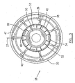
- a spoke casing 32 includes an annular inner case 34 coaxially disposed within the outer case 30 and a plurality of (at least three, but seven in this example) load transfer spokes 36 radially extending between the outer case 30 and the inner case 34.
- the inner case 34 generally includes an annular axial wall 38 and truncated conical wall 33 smoothly connected through a curved annular configuration 35 to the annular axial wall 38 and an inner annular wall 31 having a flange (not numbered) for connection to a bearing housing 50, described further below.
- a pair of gussets or stiffener ribs 89 extends from conical wall 33 to an inner side of axial wall 38 to provide locally increased radial stiffness in the region of spokes 36 without increasing the wall thickness of the inner case 34.
- the spoke casing 32 supports a bearing housing 50 which surrounds a main shaft of the engine such as shaft 12, in order to accommodate one or more bearing assemblies therein, such as those indicated by numerals 102, 104 (shown in broken lines in FIG. 4 ).
- the bearing housing 50 is centered within the annular outer case 30 and is connected to the spoke casing 32, which will be further described below.
- the load transfer spokes 36 are each affixed at an inner end 48 thereof, to the axial wall 38 of the inner case 34, for example by welding.
- the spokes 36 may either be solid or hollow - in this example, at least some are hollow (e.g. see FIG. 2 ), with a central passage 78a therein.
- Each of the load transfer spokes 36 is connected at an outer end 47 (see FIG. 9 ) thereof, to the outer case 30, by a plurality of fasteners 42.
- the fasteners 42 extend radially through openings 46 (see FIG. 5 ) defined in the outer case 30, and into holes 44 defined in the outer end 47 of the spoke 36.
- the load transfer spokes 36 each have a central axis 37 and the respective axes 37 of the plurality of load transfer spokes 36 extend in a radial plane (i.e. the paper defined by the page in FIG. 3 ).
- the outer case 30 includes a plurality of (seven, in this example) support bosses 39, each being defined as having a flat base substantially normal to the spoke axis 37. Therefore, the load transfer spokes 36 are generally perpendicular to the flat bases of the respective support bosses 39 of the outer case 30.
- the support bosses 39 are formed by a plurality of respective recesses 40 defined in the outer case 30.
- the recesses 40 are circumferentially spaced apart one from another corresponding to the angular position of the respective load transfer spokes 36.
- the openings 49 with inner threads, as shown in FIG. 9 are provided through the bosses 39.
- the outer case 30 in this embodiment has a truncated conical configuration in which a diameter of a rear end of the outer case 30 is larger than a diameter of a front end of the outer case 30. Therefore, a depth of the boss 39/recess 40 varies, decreasing from the front end to the rear end of the outer case 30. A depth of the recesses 40 near to zero at the rear end of the outer case 30 to allow axial access for the respective load transfer spokes 36 which are an integral part of the spoke casing 32. This allows the spokes 36 to slide axially forwardly into respective recesses 40 when the spoke casing 32 is slide into the outer case 30 from the rear side during mid turbine frame assembly, which will be further described hereinafter.
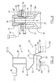
- the bearing housing 50 includes an annular axial wall 52 detachably mounted to an annular inner end of the truncated conical wall 33 of the spoke casing 32, and one or more annular bearing support legs for accommodating and supporting one or more bearing assemblies, for example a first annular bearing support leg 54 and a second annular bearing support leg 56 according to one embodiment.
- the first and second annular bearing support legs 54 and 56 extend radially and inwardly from a common point 51 on the axial wall 52 (i.e.
- the mid turbine frame system 28 provides a load transfer link or system from the bearings 102 and 104 to the outer case 30, and thus to the core casing 13 of the engine.
- annular wall 52 there is a generally U- or hairpin-shaped axially oriented apparatus formed by the annular wall 52, the truncated conical wall 33, the curved annular wall 35 and the annular axial wall 38, which co-operate to provide an arrangement which may be tuned to provide a desired flexibility/stiffness to the MTF by permitting flexure between spokes 36 and the bearing housing 50.
- the two annular bearing support legs 54 and 56 which connect to the U- or hairpin-shaped apparatus at the common joint 51, provide a sort of inverted V-shaped apparatus between the hairpin apparatus and the bearings, which may permit the radial flexibility/stiffness of each of the bearing assemblies 102, 104 to vary from one another, allowing the designer to provide different radial stiffness requirements to a plurality of bearings within the same bearing housing.
- bearing 102 supports the high pressure spool while bearing 104 the low pressure spool - it may be desirable for the shafts to be supported with differing radial stiffnesses, and the present approach permits such a design to be achieved.
- Flexibility/stiffness may be tuned to desired levels by adjusting the bearing leg shape (for example, the conical or cylindrical shape of the legs 54,56 and extensions 62,68), axial position of legs 54, 56 relative to bearings 102, 104, the thicknesses of the legs, extensions and bearing supports, materials used, etc., as will be understood by the skilled reader.
- the bearing leg shape for example, the conical or cylindrical shape of the legs 54,56 and extensions 62,68
- axial position of legs 54, 56 relative to bearings 102, 104 the thicknesses of the legs, extensions and bearing supports, materials used, etc.
- Additional support structures may also be provided to support seals, such as seal 81 supported on the inner case 34, and seals 83 and 85 supported on the bearing housing 50.
- annular bearing support legs 54, 56 may further include a sort of mechanical "fuse", indicated by numerals 58 and 60 in FIG. 4 , intended to preferentially fail during a severe load event such as a bearing seizure.
- a "fuse” may be provided by a plurality of (e.g. say, 6) circumferential slots 58 and 60 respectively defined circumferentially spaced apart one from another around the first and second bearing support legs 54 and 56.
- slots 58 may be defined radially through the annular first bearing support leg 54.
- Slots 58 may be located in the axial extension 62 and axially between a bearing support section 64 and a seal section 66 in order to fail only in the bearing support section 64 should bearing 102 seize. That is, the slots are sized such that the bearing leg is capable of handling normal operating load, but is incapable of transferring ultimate loads therethrough to the MTF.
- Such a preferential failure mechanism may help protect, for example, oil feed lines or similar components, which may pass through the MTF (e.g. through passage 78), from damage causing oil leaks (i.e.
- the slots 60 may be defined radially through the second annular bearing leg 56. Slots 60 may be located in the axial extension 68 and axially between a bearing support section 70 and a seal section 72 in order to fail only in the bearing support section 70 should bearing 104 seize. This failure mechanism also protects against possible fire risk of the type already described, and may allow the seal section 72 of the second annular bearing leg 56 to maintain a central position of a rotor supported by the bearing, in this example the low pressure spool assembly, until the engine stops.
- the slots 58, 60 thus create a strength-reduced area in the bearing leg which the designer may design to limit torsional load transfer through leg, such that this portion of the leg will preferentially fail if torsional load transfer increases above a predetermined limit. As already explained, this allows the designer to provide means for keeping the rotor centralized during the unlikely event of a bearing seizure, which may limit further damage to the engine.
- the mid turbine frame system 28 may be provided with a plurality of radial locators 74 for radially positioning the spoke casing 32 (and thus, ultimately, the bearings 102, 104) with respect to the outer case 30.
- a plurality of radial locators 74 for radially positioning the spoke casing 32 (and thus, ultimately, the bearings 102, 104) with respect to the outer case 30.
- surfaces 30a and 64a are concentric after assembly is complete.
- the number of radial locators may be less than the number of spokes.
- the radial locators 74 may be radially adjustably attached to the outer case 30 and abutting the outer end of the respective load transfer spokes 36.
- the radial locators 74 include a threaded stem 76 and a head 75.
- Head 75 may be any suitable shape to co-operate with a suitable torque applying tool (not shown).
- the threaded stem 76 is rotatably received through a threaded opening 49 defined through the support boss 39 to contact an outer end surface 45 of the end 47 of the respective load transfer spoke 36.
- the outer end surface 45 of the load transfer spoke 36 may be normal to the axis of the locator 74, such that the locator 74 may apply only a radial force to the spoke 36 when tightened.
- a radial gap "d" (see FIG. 9 ) may be provided between the outer end surface 45 of the load transfer spoke 36 and the support boss 39.
- Spoke casing 32 is thus adjustable through adjustment of the radial locators 74, thereby permitting centring of the spoke casing 32, and thus the bearing housing 50, relative to the outer case 30.
- Use of the radial locators 72 will be described further below.
- One or more of the radial locators 74 and spokes 36 may have a radial passage 78 extending through them, in order to provide access through the central passage 78a of the load transfer spokes 36 to an inner portion of the engine, for example, for oil lines or other services (not depicted).
- the radial locator assembly may be used with other mid turbine configurations and further is not limited to use with so-called “cold strut” mid turbine frames or other similar type engine cases, but rather may be employed on any suitable gas turbine casing arrangements.
- a suitable locking apparatus may be provided to lock the radial locators 74 in position, once installed and the spoke casing is centered.
- a lock washer 80 including holes 43 and radially extending arms 82 is secured to the support boss 39 of the outer case 30 by the fasteners 42 which are also used to secure the load transfer spokes 36 (once centered) to the outer case 30.
- the radial locator 74 is provided with flats 84, such as hexagon surfaces defined in an upper portion of the stem 76.
- the radially extending arms 82 of the lock washer 80 may then be deformed to pick up on the flats 84 (as indicated by broken line 82' in FIG. 9 ) in order to prevent rotation of the radial locator 74. This allows the radial positioning of the spoke casing to be fixed once centered.
- lock washer 80a having a hexagonal pocket shape, with flats 82a defined in the pocket interior, fits over flats 84a of head 75 of radial locator 74, where radial locator 74 has a hexagonal head shape.
- lock washer 80a is installed over head 75, with the flats 82a aligned with head flats 84a.
- Fasteners 42 are then attached into case 30 through holes 43a, to secure lock washer 80a in position, and secure the load transfer spokes 36 to the outer case 30.
- holes 43a are actually angular slots defined to ensure fasteners 42 will always be able to fasten lock washer 80a in the holes provided in case 30, regardless of a desired final head orientation for radial locator 74. As may be seen in FIG. 14 , this type of lock washer 80a may also provide sealing by blocking air leakage through hole 49.
- a conventional lock washer is retained by the same bolt that requires the locking device - i.e. the head typically bears downwardly on the upper surface of the part in which the bolt is inserted.
- the conventional approach presents problems.
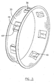
- the mid turbine frame system 28 may include an interturbine duct (ITD) assembly 110, such as a segmented strut-vane ring assembly (also referred to as an ITD-vane ring assembly), disposed within and supported by the outer case 30.
- the ITD assembly 110 includes coaxial outer and inner rings 112, 114 radially spaced apart and interconnected by a plurality of radial hollow struts 116 (at least three) and a plurality of radial airfoil vanes 118.
- the number of hollow struts 116 is less than the number of the airfoil vanes 118 and equivalent to the number of load transfer spokes 36 of the spoke casing 32.
- the hollow struts 116 function substantially as a structural linkage between the outer and inner rings 112 and 114.
- the hollow struts 116 are aligned with openings (not numbered) defined in the respective outer and inner rings 112 and 114 to allow the respective load transfer spokes 36 of the spoke casing 32 to radially extend through the ITD assembly 110 to be connected to the outer case 30.
- the hollow struts 116 also define an aerodynamic airfoil outline to reduce fluid flow resistance to combustion gases flowing through an annular gas path 120 defined between the outer and inner rings 112, 114.
- the airfoil vanes 118 are employed substantially for directing these combustion gases.
- the load transfer spokes 36 provide a so-called “cold strut” arrangement, as they are protected from high temperatures of the combustion gases by the surrounding wall of the respective struts 116, and the associated air gap between struts 116 and spokes 36, both of which provide a relatively "cold” working environment for the spokes to react and transfer bearing loads,
- conventional "hot" struts are both aerodynamic and structural, and are thus exposed both to hot combustion gases and bearing load stresses.
- the ITD assembly 110 includes a plurality of circumferential segments 122.
- Each segment 122 includes a circumferential section of the outer and inner rings 112, 114 interconnected by only one of the hollow struts 116 and by a number of airfoil vanes 118. Therefore, each of the segments 122 can be attached to the spoke casing 32 during an assembly procedure, by inserting the segment 122 radially inwardly towards the spoke casing 32 and allowing one of the load transfer spokes 36 to extend radially through the hollow strut 116.
- Suitable retaining elements or vane lugs 124 and 126 may be provided, for example, towards the upstream edge and downstream edge of the outer ring 112 (see FIG. 2 ), for engagement with corresponding retaining elements or case slots 124', 126', on the inner side of the outer case 30.
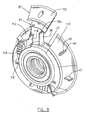
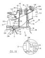
- mid turbine frame 28 is shown again, but in this view an upstream turbine stage which is part of the high pressure turbine assembly 24 of FIG. 1 , comprising a turbine rotor (not numbered) having a disc 200 and turbine blade array 202, is shown, and also shown is a portion of the low pressure turbine case 204 connected to a downstream side of MTF 28 (fasteners shown but not numbered).
- the turbine disc 200 is mounted to the turbine shaft 20 of FIG. 1 .
- a upstream edge 206 of inner ring 114 of the ITD assembly 110 extends forwardly (i.e. to the left in FIG.
- a suitable axial gap g 1 may be provided between the disc 200 and the upstream edge 206 of the ITD assembly 110.
- the gaps g 1 may be smaller than g 3 as shown in the circled area "D" in an enlarged scale.
- seal arrangement 91-93 at a upstream edge portion of the ITD assembly 110 provides simple radial supports (i.e. the inner ring 114 is simply supported in a radial direction by inner case 34) which permits an axial sliding relationship between the inner ring 114 and the spoke case 32.
- axial gap g 2 is provided between the upstream edge of the load transfer spokes 36 and the inner periphery of the hollow struts 116, and hence some axial movement of the ITD assembly 110 can occur before strut 116 would contact spoke 36 of spoke casing 32.
- vane lugs 124 and 126 are forwardly inserted into case slots 124', 126', and thus may be permitted to slide axially rearwardly relative to outer case 30.
- outer ring 112 of the ITD assembly 110 abuts a downstream catcher 208 on low pressure turbine case 204, and thus axial rearward movement of the ITD assembly 110 would be restrained by low turbine casing 204.
- the ITD assembly 110 is slidingly supported by the spoke casing 32, and may also be permitted to move axially rearwardly of outer case 30 without contacting spoke casing 32 (for at least the distance g 2 ), however, axial rearward movement would be restrained by low pressure turbine case 204, via catcher 208.
- a load path for transmitting loads induced by axial rearward movement of the turbine disc 200 in a shaft shear event is thus provided through ITD assembly 110 independent of MTF 28, thereby protecting MTF 28 from such loads, provided that gap g 2 is appropriately sized, as will be appreciated by the skilled reader in light of this description. Considerations such as the expected loads, the strength of the ITD assembly, etc. will affect the sizing of the gaps. For example, the respective gaps g 2 and g 3 may be greater than an expected interturbine duct upstream edge deflection during a shaft shear event.
- this load transfer mechanism may be used with other cold strut mid turbine frame designs. Although described as being useful to transfer axial loads incurred during a shaft shear event, the present mechanism may also or additionally be used to transfer other primarily axial loads to the engine case independently of the spoke casing assembly.
- Assembly of a sub-assembly may be conducted in any suitable manner, depending on the specific configuration of the mid turbine frame system 28. Assembly of the mid turbine frame system 28 shown in FIG. 8 may occur from the inside out, beginning generally with the spoke casing 32, to which the bearing housing 50 may be mounted by fasteners 53. A piston ring 91 may be mounted at the front end of the spoke casing.
- a front inner seal housing ring 93 is axially slid over piston ring 91.
- the vane segments 122 are then individually, radially and inwardly inserted over the spokes 36 for attachment to the spoke casing 32.
- Feather seals 87 FIG. 8
- a flange (not numbered) at the front edge of each segment 122 is inserted into seal housing ring 93.
- a rear inner seal housing ring 94 is installed over a flange (not numbered) at the rear end of each segment.
- the outer ends 47 of the respective load transfer spokes 36 are circumferentially aligned with the respective radial locators 74 which are adjustably threadedly engaged with the openings 49 of the outer case 30.
- the ITD assembly 110 is then inserted into the outer case 30 by moving them axially towards one another until the sub-assembly is situated in place within the outer case 30 (suitable fixturing may be employed, in particular, to provide concentricity between surface 30a of case 30 and surface 64a of the ITD assembly 110).
- the ITD assembly 110 may be inserted within the outer case 30 by moving the sub-assembly axially into the rear end of the outer case 30.
- the ITD assembly 110 is mounted to the outer case 30 by inserting lugs 124 and 126 on the outer ring 112 to engage corresponding slots 124', 126' on the inner side of the case 30, as described above.
- the radial locators 74 are then individually inserted into case 30 from the outside, and adjusted to abut the outer surfaces 45 of the ends 47 of the respective spokes 36 in order to adjust radial gap "d" between the outer ends 47 of the respective spokes 36 and the respective support bosses 39 of the outer case 30, thereby centering the annular bearing housing 50 within the outer case 30.
- the radial locators 74 may be selectively rotated to make fine adjustments to change an extent of radial inward protrusion of the end section of the stem 76 of the respective radial locators 74 into the support bosses 39 of the outer case 30, while maintaining contact between the respective outer ends surfaces 45 of the respective spokes 36 and the respective radial locators 74, as required for centering the bearing housing 50 within the outer case 30.
- the plurality of fasteners 42 are radially inserted through the holes 46 defined in the support bosses 39 of the outer case 30, and are threadedly engaged with the holes 44 defined in the outer surfaces 45 of the end 47 of the load transfer spokes 36, to secure the ITD assembly 110 to the outer case 30.
- the step of fastening the fasteners 42 to secure the ITD assembly 110 may affect the centring of the bearing housing 50 within the outer case 30 and, therefore, further fine adjustments in both the fastening step and the step of adjusting radial locators 74 may be required. These two steps may therefore be conducted in a cooperative manner in which the fine adjustments of the radial locators 74 and the fine adjustments of the fasteners 42 may be conducted alternately and/or in repeated sequences until the sub-assembly is adequately secured within the outer case 30 and the bearing housing 50 is centered within the outer case 30.
- a fixture may be used to roughly center the bearing housing of the sub-assembly relative to the outer case 30 prior to the step of adjusting the radial locators 74.
- the fasteners may be attached to the outer case and loosely connected to the respective spoke prior to attachment of the radial locaters 74 to the outer case 30, to hold the sub-assembly within the outer case 30 but allow radial adjustment of the sub-assembly within the outer case 30.
- Front baffle 95 and rear baffle 96 are then installed, for example with fasteners 55.
- Rear baffle includes a seal 92 cooperating in rear inner seal housing ring 94 to, for example, impede hot gas ingestion from the gas path into the area around the MTF.
- the outer case 30 may then by bolted (bolts shown but not numbered) to the remainder of the core casing 13 in a suitable manner.
- Disassembly of the mid turbine frame system is substantially a procedure reversed to the above-described steps, except for those central position adjustments of the bearing housing within the outer case which need not be repeated upon disassembly.
- segmented strut-vane ring assembly may be configured differently from that described and illustrated in this application and engines of various types other than the described turbofan bypass duct engine will also be suitable for application of the described concept.
- the radial locator/centring features described above are not limited to mid turbine frames of the present description, or to mid turbine frames at all, but may be used in other case sections needing to be centered in the engine, such as other bearing points along the engine case, e.g. a compressor case housing a bearing(s).
- the features described relating to the bearing housing and/or mid turbine load transfer arrangements are likewise not limited in application to mid turbine frames, but may be used wherever suitable.
- the bearing housing need not be separable from the spoke casing.
- the locking apparatus of FIGS. 12-14 need not involved cooperating flat surfaces as depicted, but my include any cooperative features which anti-rotate the radial locators, for example dimples of the shaft or head of the locator, etc. Any number (including one) of locking surfaces may be provided on the locking apparatus. Still other modifications which fall within the scope of the described subject matter will be apparent to those skilled in the art, in light of a review of this disclosure, and such modifications are intended to fall within the appended claims.
Landscapes
- Engineering & Computer Science (AREA)
- Mechanical Engineering (AREA)
- General Engineering & Computer Science (AREA)
- Physics & Mathematics (AREA)
- Fluid Mechanics (AREA)
- Turbine Rotor Nozzle Sealing (AREA)
Applications Claiming Priority (1)
| Application Number | Priority Date | Filing Date | Title |
|---|---|---|---|
| US12/325,009 US8099962B2 (en) | 2008-11-28 | 2008-11-28 | Mid turbine frame system and radial locator for radially centering a bearing for gas turbine engine |
Publications (3)
| Publication Number | Publication Date |
|---|---|
| EP2192273A2 true EP2192273A2 (de) | 2010-06-02 |
| EP2192273A3 EP2192273A3 (de) | 2012-12-26 |
| EP2192273B1 EP2192273B1 (de) | 2014-09-17 |
Family
ID=41259470
Family Applications (1)
| Application Number | Title | Priority Date | Filing Date |
|---|---|---|---|
| EP09252334.9A Active EP2192273B1 (de) | 2008-11-28 | 2009-10-01 | Gasturbine mit einer Zentriervorrichtung und Montageverfahren dafür |
Country Status (3)
| Country | Link |
|---|---|
| US (1) | US8099962B2 (de) |
| EP (1) | EP2192273B1 (de) |
| CA (1) | CA2672328C (de) |
Cited By (6)
| Publication number | Priority date | Publication date | Assignee | Title |
|---|---|---|---|---|
| WO2013085435A1 (en) | 2011-12-08 | 2013-06-13 | Volvo Aero Corporation | Gas turbine engine component |
| US9611859B2 (en) | 2012-01-31 | 2017-04-04 | United Technologies Corporation | Gas turbine engine with high speed low pressure turbine section and bearing support features |
| US10443449B2 (en) | 2015-07-24 | 2019-10-15 | Pratt & Whitney Canada Corp. | Spoke mounting arrangement |
| EP3546704A3 (de) * | 2018-03-30 | 2019-12-18 | United Technologies Corporation | Turboluftstrahltriebwerksgehäuse mit lagergehäuse |
| US11608786B2 (en) | 2012-04-02 | 2023-03-21 | Raytheon Technologies Corporation | Gas turbine engine with power density range |
| US11913349B2 (en) | 2012-01-31 | 2024-02-27 | Rtx Corporation | Gas turbine engine with high speed low pressure turbine section and bearing support features |
Families Citing this family (42)
| Publication number | Priority date | Publication date | Assignee | Title |
|---|---|---|---|---|
| US8371127B2 (en) * | 2009-10-01 | 2013-02-12 | Pratt & Whitney Canada Corp. | Cooling air system for mid turbine frame |
| US8992167B2 (en) * | 2011-09-07 | 2015-03-31 | General Electric Company | Turbine casing assembly mounting pin |
| US9279341B2 (en) | 2011-09-22 | 2016-03-08 | Pratt & Whitney Canada Corp. | Air system architecture for a mid-turbine frame module |
| US8992173B2 (en) * | 2011-11-04 | 2015-03-31 | United Technologies Corporation | Tie-rod nut including a nut flange with a plurality of mounting apertures |
| US8920113B2 (en) | 2011-11-28 | 2014-12-30 | United Technologies Corporation | Thermal gradiant tolerant turbomachine coupling member |
| US8979484B2 (en) | 2012-01-05 | 2015-03-17 | Pratt & Whitney Canada Corp. | Casing for an aircraft turbofan bypass engine |
| US9316117B2 (en) | 2012-01-30 | 2016-04-19 | United Technologies Corporation | Internally cooled spoke |
| US9255487B2 (en) | 2012-01-31 | 2016-02-09 | United Technologies Corporation | Gas turbine engine seal carrier |
| WO2013128683A1 (ja) * | 2012-02-27 | 2013-09-06 | 三菱重工業株式会社 | ガスタービン |
| US10036350B2 (en) * | 2012-04-30 | 2018-07-31 | United Technologies Corporation | Geared turbofan with three turbines all co-rotating |
| US9217371B2 (en) | 2012-07-13 | 2015-12-22 | United Technologies Corporation | Mid-turbine frame with tensioned spokes |
| US9587514B2 (en) * | 2012-07-13 | 2017-03-07 | United Technologies Corporation | Vane insertable tie rods with keyed connections |
| US9222413B2 (en) | 2012-07-13 | 2015-12-29 | United Technologies Corporation | Mid-turbine frame with threaded spokes |
| US10167779B2 (en) * | 2012-09-28 | 2019-01-01 | United Technologies Corporation | Mid-turbine frame heat shield |
| WO2014105604A1 (en) * | 2012-12-29 | 2014-07-03 | United Technologies Corporation | Angled cut to direct radiative heat load |
| US9890659B2 (en) | 2013-02-11 | 2018-02-13 | United Technologies Corporation | Mid-turbine frame vane assembly support with retention unit |
| EP2959119B1 (de) | 2013-02-22 | 2018-10-03 | United Technologies Corporation | Gasturbinenmotorbefestigungsstruktur und verfahren dafür |
| WO2014137574A1 (en) | 2013-03-05 | 2014-09-12 | United Technologies Corporation | Mid-turbine frame rod and turbine case flange |
| US10221707B2 (en) | 2013-03-07 | 2019-03-05 | Pratt & Whitney Canada Corp. | Integrated strut-vane |
| US10330011B2 (en) * | 2013-03-11 | 2019-06-25 | United Technologies Corporation | Bench aft sub-assembly for turbine exhaust case fairing |
| US10344603B2 (en) * | 2013-07-30 | 2019-07-09 | United Technologies Corporation | Gas turbine engine turbine vane ring arrangement |
| US9835038B2 (en) | 2013-08-07 | 2017-12-05 | Pratt & Whitney Canada Corp. | Integrated strut and vane arrangements |
| US9458737B2 (en) | 2013-10-04 | 2016-10-04 | Siemens Energy, Inc. | Adjustable bracing apparatus and assembly method for gas turbine exhaust diffuser |
| US9556746B2 (en) | 2013-10-08 | 2017-01-31 | Pratt & Whitney Canada Corp. | Integrated strut and turbine vane nozzle arrangement |
| US9598981B2 (en) * | 2013-11-22 | 2017-03-21 | Siemens Energy, Inc. | Industrial gas turbine exhaust system diffuser inlet lip |
| US20160146052A1 (en) | 2014-11-25 | 2016-05-26 | United Technologies Corporation | Forged cast forged outer case for a gas turbine engine |
| US9879637B2 (en) | 2014-12-04 | 2018-01-30 | Honeywell International Inc. | Combined fan bypass components with removable front frame structure for use in a turbofan engine and method for making same |
| US10077676B2 (en) * | 2015-01-16 | 2018-09-18 | Siemens Energy, Inc. | Turbine exhaust cylinder/turbine exhaust manifold bolted full span turbine exhaust flaps |
| US10161256B2 (en) | 2015-01-22 | 2018-12-25 | Untied Technologies Corporation | Seal with backup seal |
| US10215098B2 (en) * | 2015-01-22 | 2019-02-26 | United Technologies Corporation | Bearing compartment seal |
| US9822667B2 (en) | 2015-04-06 | 2017-11-21 | United Technologies Corporation | Tri-tab lock washer |
| US10247035B2 (en) | 2015-07-24 | 2019-04-02 | Pratt & Whitney Canada Corp. | Spoke locking architecture |
| US9909434B2 (en) | 2015-07-24 | 2018-03-06 | Pratt & Whitney Canada Corp. | Integrated strut-vane nozzle (ISV) with uneven vane axial chords |
| CA2936180A1 (en) | 2015-07-24 | 2017-01-24 | Pratt & Whitney Canada Corp. | Multiple spoke cooling system and method |
| JP6546481B2 (ja) * | 2015-08-31 | 2019-07-17 | 川崎重工業株式会社 | 排気ディフューザ |
| US10273812B2 (en) | 2015-12-18 | 2019-04-30 | Pratt & Whitney Canada Corp. | Turbine rotor coolant supply system |
| US10443451B2 (en) | 2016-07-18 | 2019-10-15 | Pratt & Whitney Canada Corp. | Shroud housing supported by vane segments |
| DE102016217320A1 (de) * | 2016-09-12 | 2018-03-15 | Siemens Aktiengesellschaft | Gasturbine mit getrennter Kühlung für Turbine und Abgasgehäuse |
| FR3078370B1 (fr) * | 2018-02-28 | 2020-02-14 | Safran Helicopter Engines | Ensemble pour une turbomachine |
| JP6773747B2 (ja) * | 2018-10-18 | 2020-10-21 | ファナック株式会社 | 射出成形機の機台 |
| US10844745B2 (en) | 2019-03-29 | 2020-11-24 | Pratt & Whitney Canada Corp. | Bearing assembly |
| US11492926B2 (en) | 2020-12-17 | 2022-11-08 | Pratt & Whitney Canada Corp. | Bearing housing with slip joint |
Citations (4)
| Publication number | Priority date | Publication date | Assignee | Title |
|---|---|---|---|---|
| GB2112084A (en) * | 1981-10-30 | 1983-07-13 | Rolls Royce | Bearing support structure |
| US4979872A (en) * | 1989-06-22 | 1990-12-25 | United Technologies Corporation | Bearing compartment support |
| US5160251A (en) * | 1991-05-13 | 1992-11-03 | General Electric Company | Lightweight engine turbine bearing support assembly for withstanding radial and axial loads |
| EP1655457A1 (de) * | 2004-10-29 | 2006-05-10 | General Electric Company | Gasturbine und Verfahren zu deren Montage |
Family Cites Families (58)
| Publication number | Priority date | Publication date | Assignee | Title |
|---|---|---|---|---|
| US2692724A (en) | 1942-07-02 | 1954-10-26 | Power Jets Res & Dev Ltd | Turbine rotor mounting |
| US2620157A (en) | 1947-05-06 | 1952-12-02 | Rolls Royce | Gas-turbine engine |
| US2616662A (en) | 1949-01-05 | 1952-11-04 | Westinghouse Electric Corp | Turbine bearing support structure |
| US2639579A (en) | 1949-06-21 | 1953-05-26 | Hartford Nat Bank & Trust Co | Turbojet engine having tail pipe ejector to induce flow of cooling air |
| US2928648A (en) | 1954-03-01 | 1960-03-15 | United Aircraft Corp | Turbine bearing support |
| US2941781A (en) | 1955-10-13 | 1960-06-21 | Westinghouse Electric Corp | Guide vane array for turbines |
| US2829014A (en) | 1957-04-03 | 1958-04-01 | United Aircarft Corp | Turbine bearing support |
| US2919888A (en) | 1957-04-17 | 1960-01-05 | United Aircraft Corp | Turbine bearing support |
| US2869941A (en) | 1957-04-29 | 1959-01-20 | United Aircraft Corp | Turbine bearing support |
| US3084849A (en) | 1960-05-18 | 1963-04-09 | United Aircraft Corp | Inlet and bearing support for axial flow compressors |
| US3261587A (en) | 1964-06-24 | 1966-07-19 | United Aircraft Corp | Bearing support |
| US3312448A (en) | 1965-03-01 | 1967-04-04 | Gen Electric | Seal arrangement for preventing leakage of lubricant in gas turbine engines |
| US3628884A (en) * | 1970-06-26 | 1971-12-21 | Westinghouse Electric Corp | Method and apparatus for supporting an inner casing structure |
| US3844115A (en) | 1973-02-14 | 1974-10-29 | Gen Electric | Load distributing thrust mount |
| US4245951A (en) | 1978-04-26 | 1981-01-20 | General Motors Corporation | Power turbine support |
| FR2432176A1 (fr) * | 1978-07-25 | 1980-02-22 | Thomson Csf | Formation de voies sonar par des dispositifs a transfert de charge |
| US4304522A (en) | 1980-01-15 | 1981-12-08 | Pratt & Whitney Aircraft Of Canada Limited | Turbine bearing support |
| US4478551A (en) | 1981-12-08 | 1984-10-23 | United Technologies Corporation | Turbine exhaust case design |
| FR2535789A1 (fr) | 1982-11-10 | 1984-05-11 | Snecma | Montage d'un palier inter-arbres de turbomachine multi-corps |
| US4987736A (en) * | 1988-12-14 | 1991-01-29 | General Electric Company | Lightweight gas turbine engine frame with free-floating heat shield |
| US4965994A (en) | 1988-12-16 | 1990-10-30 | General Electric Company | Jet engine turbine support |
| GB2236809B (en) * | 1989-09-22 | 1994-03-16 | Rolls Royce Plc | Improvements in or relating to gas turbine engines |
| US5131811A (en) * | 1990-09-12 | 1992-07-21 | United Technologies Corporation | Fastener mounting for multi-stage compressor |
| SE500743C2 (sv) | 1992-04-01 | 1994-08-22 | Abb Carbon Ab | Sätt och anordning för montering av axialströmningsmaskin |
| US5483792A (en) | 1993-05-05 | 1996-01-16 | General Electric Company | Turbine frame stiffening rails |
| US5361580A (en) | 1993-06-18 | 1994-11-08 | General Electric Company | Gas turbine engine rotor support system |
| US5307622A (en) | 1993-08-02 | 1994-05-03 | General Electric Company | Counterrotating turbine support assembly |
| US5443229A (en) | 1993-12-13 | 1995-08-22 | General Electric Company | Aircraft gas turbine engine sideways mount |
| US5438756A (en) | 1993-12-17 | 1995-08-08 | General Electric Company | Method for assembling a turbine frame assembly |
| US5609467A (en) * | 1995-09-28 | 1997-03-11 | Cooper Cameron Corporation | Floating interturbine duct assembly for high temperature power turbine |
| US5634767A (en) | 1996-03-29 | 1997-06-03 | General Electric Company | Turbine frame having spindle mounted liner |
| US5813214A (en) | 1997-01-03 | 1998-09-29 | General Electric Company | Bearing lubrication configuration in a turbine engine |
| US5746574A (en) | 1997-05-27 | 1998-05-05 | General Electric Company | Low profile fluid joint |
| DE69939863D1 (de) | 1998-11-05 | 2008-12-18 | Mazda Motor | Fahrzeugaufhängungsvorrichtung |
| US6185925B1 (en) | 1999-02-12 | 2001-02-13 | General Electric Company | External cooling system for turbine frame |
| US6158102A (en) | 1999-03-24 | 2000-12-12 | General Electric Co. | Apparatus and methods for aligning holes through wheels and spacers and stacking the wheels and spacers to form a turbine rotor |
| JP3482196B2 (ja) | 2001-03-02 | 2003-12-22 | 三菱重工業株式会社 | 可変容量タービンの組立・調整方法およびその装置 |
| JP4363799B2 (ja) * | 2001-06-08 | 2009-11-11 | 株式会社東芝 | タービン組立輸送架台および同架台を用いたタービン組立方法、輸送方法 |
| US6708482B2 (en) | 2001-11-29 | 2004-03-23 | General Electric Company | Aircraft engine with inter-turbine engine frame |
| US6796765B2 (en) | 2001-12-27 | 2004-09-28 | General Electric Company | Methods and apparatus for assembling gas turbine engine struts |
| US6619030B1 (en) | 2002-03-01 | 2003-09-16 | General Electric Company | Aircraft engine with inter-turbine engine frame supported counter rotating low pressure turbine rotors |
| EP1389690B1 (de) * | 2002-08-16 | 2007-01-03 | Siemens Aktiengesellschaft | Innenkühlbare Schraube |
| US6763654B2 (en) | 2002-09-30 | 2004-07-20 | General Electric Co. | Aircraft gas turbine engine having variable torque split counter rotating low pressure turbines and booster aft of counter rotating fans |
| US6935837B2 (en) | 2003-02-27 | 2005-08-30 | General Electric Company | Methods and apparatus for assembling gas turbine engines |
| FR2852053B1 (fr) * | 2003-03-06 | 2007-12-28 | Snecma Moteurs | Turbine haute pression pour turbomachine |
| US6905303B2 (en) | 2003-06-30 | 2005-06-14 | General Electric Company | Methods and apparatus for assembling gas turbine engines |
| US7334981B2 (en) | 2004-10-29 | 2008-02-26 | General Electric Company | Counter-rotating gas turbine engine and method of assembling same |
| US7269938B2 (en) | 2004-10-29 | 2007-09-18 | General Electric Company | Counter-rotating gas turbine engine and method of assembling same |
| US7874802B2 (en) | 2004-12-01 | 2011-01-25 | United Technologies Corporation | Tip turbine engine comprising turbine blade clusters and method of assembly |
| FR2890110B1 (fr) | 2005-08-26 | 2007-11-02 | Snecma | Procede d'assemblage d'une turbomachine |
| US7341429B2 (en) | 2005-11-16 | 2008-03-11 | General Electric Company | Methods and apparatuses for cooling gas turbine engine rotor assemblies |
| US7677047B2 (en) | 2006-03-29 | 2010-03-16 | United Technologies Corporation | Inverted stiffened shell panel torque transmission for loaded struts and mid-turbine frames |
| US7775049B2 (en) | 2006-04-04 | 2010-08-17 | United Technologies Corporation | Integrated strut design for mid-turbine frames with U-base |
| US7610763B2 (en) | 2006-05-09 | 2009-11-03 | United Technologies Corporation | Tailorable design configuration topologies for aircraft engine mid-turbine frames |
| US7600370B2 (en) | 2006-05-25 | 2009-10-13 | Siemens Energy, Inc. | Fluid flow distributor apparatus for gas turbine engine mid-frame section |
| US7594404B2 (en) | 2006-07-27 | 2009-09-29 | United Technologies Corporation | Embedded mount for mid-turbine frame |
| US7762087B2 (en) | 2006-12-06 | 2010-07-27 | United Technologies Corporation | Rotatable integrated segmented mid-turbine frames |
| US7797946B2 (en) | 2006-12-06 | 2010-09-21 | United Technologies Corporation | Double U design for mid-turbine frame struts |
-
2008
- 2008-11-28 US US12/325,009 patent/US8099962B2/en active Active
-
2009
- 2009-07-15 CA CA2672328A patent/CA2672328C/en not_active Expired - Fee Related
- 2009-10-01 EP EP09252334.9A patent/EP2192273B1/de active Active
Patent Citations (4)
| Publication number | Priority date | Publication date | Assignee | Title |
|---|---|---|---|---|
| GB2112084A (en) * | 1981-10-30 | 1983-07-13 | Rolls Royce | Bearing support structure |
| US4979872A (en) * | 1989-06-22 | 1990-12-25 | United Technologies Corporation | Bearing compartment support |
| US5160251A (en) * | 1991-05-13 | 1992-11-03 | General Electric Company | Lightweight engine turbine bearing support assembly for withstanding radial and axial loads |
| EP1655457A1 (de) * | 2004-10-29 | 2006-05-10 | General Electric Company | Gasturbine und Verfahren zu deren Montage |
Cited By (10)
| Publication number | Priority date | Publication date | Assignee | Title |
|---|---|---|---|---|
| WO2013085435A1 (en) | 2011-12-08 | 2013-06-13 | Volvo Aero Corporation | Gas turbine engine component |
| JP2015500427A (ja) * | 2011-12-08 | 2015-01-05 | ゲーコーエヌ エアロスペース スウェーデン アーベー | ガスタービンエンジン構成要素 |
| EP2788585A4 (de) * | 2011-12-08 | 2015-10-14 | Gkn Aerospace Sweden Ab | Gasturbinenmotorkomponente |
| US9611859B2 (en) | 2012-01-31 | 2017-04-04 | United Technologies Corporation | Gas turbine engine with high speed low pressure turbine section and bearing support features |
| US11913349B2 (en) | 2012-01-31 | 2024-02-27 | Rtx Corporation | Gas turbine engine with high speed low pressure turbine section and bearing support features |
| US11608786B2 (en) | 2012-04-02 | 2023-03-21 | Raytheon Technologies Corporation | Gas turbine engine with power density range |
| US11970984B2 (en) | 2012-04-02 | 2024-04-30 | Rtx Corporation | Gas turbine engine with power density range |
| US10443449B2 (en) | 2015-07-24 | 2019-10-15 | Pratt & Whitney Canada Corp. | Spoke mounting arrangement |
| EP3546704A3 (de) * | 2018-03-30 | 2019-12-18 | United Technologies Corporation | Turboluftstrahltriebwerksgehäuse mit lagergehäuse |
| US10746049B2 (en) | 2018-03-30 | 2020-08-18 | United Technologies Corporation | Gas turbine engine case including bearing compartment |
Also Published As
| Publication number | Publication date |
|---|---|
| EP2192273B1 (de) | 2014-09-17 |
| CA2672328C (en) | 2013-04-16 |
| US8099962B2 (en) | 2012-01-24 |
| EP2192273A3 (de) | 2012-12-26 |
| US20100132372A1 (en) | 2010-06-03 |
| CA2672328A1 (en) | 2010-05-28 |
Similar Documents
| Publication | Publication Date | Title |
|---|---|---|
| EP2192273B1 (de) | Gasturbine mit einer Zentriervorrichtung und Montageverfahren dafür | |
| EP2192276B1 (de) | Gasturbine umfassend Lagerträgerstruktur | |
| CA2672323C (en) | Mid turbine frame system for gas turbine engine | |
| EP2192275B1 (de) | Gasturbinenmotor | |
| CA2686658C (en) | Mid turbine frame system for gas turbine engine | |
| US8091371B2 (en) | Mid turbine frame for gas turbine engine | |
| US8500392B2 (en) | Sealing for vane segments | |
| CA2672096C (en) | Fabricated itd-strut and vane ring for gas turbine engine | |
| EP1149986B1 (de) | Turbinengehäuse | |
| US20100275572A1 (en) | Oil line insulation system for mid turbine frame | |
| GB2508260B (en) | A method for assembling a nozzle and an exhaust case of a turbomachine | |
| WO2014105425A1 (en) | Turbine frame assembly and method of designing turbine frame assembly | |
| US10301972B2 (en) | Intermediate casing for a turbomachine turbine | |
| EP3690193B1 (de) | Dichtung und fertigungsverfahren für eine dichtungsanordnung | |
| US11168575B2 (en) | Halo seal access window openings |
Legal Events
| Date | Code | Title | Description |
|---|---|---|---|
| PUAI | Public reference made under article 153(3) epc to a published international application that has entered the european phase |
Free format text: ORIGINAL CODE: 0009012 |
|
| AK | Designated contracting states |
Kind code of ref document: A2 Designated state(s): AT BE BG CH CY CZ DE DK EE ES FI FR GB GR HR HU IE IS IT LI LT LU LV MC MK MT NL NO PL PT RO SE SI SK SM TR |
|
| AX | Request for extension of the european patent |
Extension state: AL BA RS |
|
| PUAL | Search report despatched |
Free format text: ORIGINAL CODE: 0009013 |
|
| AK | Designated contracting states |
Kind code of ref document: A3 Designated state(s): AT BE BG CH CY CZ DE DK EE ES FI FR GB GR HR HU IE IS IT LI LT LU LV MC MK MT NL NO PL PT RO SE SI SK SM TR |
|
| AX | Request for extension of the european patent |
Extension state: AL BA RS |
|
| RIC1 | Information provided on ipc code assigned before grant |
Ipc: F01D 9/06 20060101ALI20121122BHEP Ipc: F01D 25/28 20060101AFI20121122BHEP |
|
| 17P | Request for examination filed |
Effective date: 20130619 |
|
| RBV | Designated contracting states (corrected) |
Designated state(s): AT BE BG CH CY CZ DE DK EE ES FI FR GB GR HR HU IE IS IT LI LT LU LV MC MK MT NL NO PL PT RO SE SI SK SM TR |
|
| GRAP | Despatch of communication of intention to grant a patent |
Free format text: ORIGINAL CODE: EPIDOSNIGR1 |
|
| INTG | Intention to grant announced |
Effective date: 20140327 |
|
| GRAS | Grant fee paid |
Free format text: ORIGINAL CODE: EPIDOSNIGR3 |
|
| GRAA | (expected) grant |
Free format text: ORIGINAL CODE: 0009210 |
|
| AK | Designated contracting states |
Kind code of ref document: B1 Designated state(s): AT BE BG CH CY CZ DE DK EE ES FI FR GB GR HR HU IE IS IT LI LT LU LV MC MK MT NL NO PL PT RO SE SI SK SM TR |
|
| REG | Reference to a national code |
Ref country code: GB Ref legal event code: FG4D |
|
| REG | Reference to a national code |
Ref country code: CH Ref legal event code: EP |
|
| REG | Reference to a national code |
Ref country code: IE Ref legal event code: FG4D |
|
| REG | Reference to a national code |
Ref country code: AT Ref legal event code: REF Ref document number: 687816 Country of ref document: AT Kind code of ref document: T Effective date: 20141015 |
|
| REG | Reference to a national code |
Ref country code: DE Ref legal event code: R096 Ref document number: 602009026696 Country of ref document: DE Effective date: 20141030 |
|
| PG25 | Lapsed in a contracting state [announced via postgrant information from national office to epo] |
Ref country code: NO Free format text: LAPSE BECAUSE OF FAILURE TO SUBMIT A TRANSLATION OF THE DESCRIPTION OR TO PAY THE FEE WITHIN THE PRESCRIBED TIME-LIMIT Effective date: 20141217 Ref country code: FI Free format text: LAPSE BECAUSE OF FAILURE TO SUBMIT A TRANSLATION OF THE DESCRIPTION OR TO PAY THE FEE WITHIN THE PRESCRIBED TIME-LIMIT Effective date: 20140917 Ref country code: GR Free format text: LAPSE BECAUSE OF FAILURE TO SUBMIT A TRANSLATION OF THE DESCRIPTION OR TO PAY THE FEE WITHIN THE PRESCRIBED TIME-LIMIT Effective date: 20141218 Ref country code: LT Free format text: LAPSE BECAUSE OF FAILURE TO SUBMIT A TRANSLATION OF THE DESCRIPTION OR TO PAY THE FEE WITHIN THE PRESCRIBED TIME-LIMIT Effective date: 20140917 Ref country code: SE Free format text: LAPSE BECAUSE OF FAILURE TO SUBMIT A TRANSLATION OF THE DESCRIPTION OR TO PAY THE FEE WITHIN THE PRESCRIBED TIME-LIMIT Effective date: 20140917 |
|
| REG | Reference to a national code |
Ref country code: NL Ref legal event code: VDEP Effective date: 20140917 |
|
| REG | Reference to a national code |
Ref country code: LT Ref legal event code: MG4D |
|
| PG25 | Lapsed in a contracting state [announced via postgrant information from national office to epo] |
Ref country code: HR Free format text: LAPSE BECAUSE OF FAILURE TO SUBMIT A TRANSLATION OF THE DESCRIPTION OR TO PAY THE FEE WITHIN THE PRESCRIBED TIME-LIMIT Effective date: 20140917 Ref country code: CY Free format text: LAPSE BECAUSE OF FAILURE TO SUBMIT A TRANSLATION OF THE DESCRIPTION OR TO PAY THE FEE WITHIN THE PRESCRIBED TIME-LIMIT Effective date: 20140917 Ref country code: LV Free format text: LAPSE BECAUSE OF FAILURE TO SUBMIT A TRANSLATION OF THE DESCRIPTION OR TO PAY THE FEE WITHIN THE PRESCRIBED TIME-LIMIT Effective date: 20140917 |
|
| REG | Reference to a national code |
Ref country code: AT Ref legal event code: MK05 Ref document number: 687816 Country of ref document: AT Kind code of ref document: T Effective date: 20140917 |
|
| PG25 | Lapsed in a contracting state [announced via postgrant information from national office to epo] |
Ref country code: NL Free format text: LAPSE BECAUSE OF FAILURE TO SUBMIT A TRANSLATION OF THE DESCRIPTION OR TO PAY THE FEE WITHIN THE PRESCRIBED TIME-LIMIT Effective date: 20140917 |
|
| PG25 | Lapsed in a contracting state [announced via postgrant information from national office to epo] |
Ref country code: RO Free format text: LAPSE BECAUSE OF FAILURE TO SUBMIT A TRANSLATION OF THE DESCRIPTION OR TO PAY THE FEE WITHIN THE PRESCRIBED TIME-LIMIT Effective date: 20140917 Ref country code: CZ Free format text: LAPSE BECAUSE OF FAILURE TO SUBMIT A TRANSLATION OF THE DESCRIPTION OR TO PAY THE FEE WITHIN THE PRESCRIBED TIME-LIMIT Effective date: 20140917 Ref country code: SK Free format text: LAPSE BECAUSE OF FAILURE TO SUBMIT A TRANSLATION OF THE DESCRIPTION OR TO PAY THE FEE WITHIN THE PRESCRIBED TIME-LIMIT Effective date: 20140917 Ref country code: EE Free format text: LAPSE BECAUSE OF FAILURE TO SUBMIT A TRANSLATION OF THE DESCRIPTION OR TO PAY THE FEE WITHIN THE PRESCRIBED TIME-LIMIT Effective date: 20140917 Ref country code: IS Free format text: LAPSE BECAUSE OF FAILURE TO SUBMIT A TRANSLATION OF THE DESCRIPTION OR TO PAY THE FEE WITHIN THE PRESCRIBED TIME-LIMIT Effective date: 20150117 Ref country code: PT Free format text: LAPSE BECAUSE OF FAILURE TO SUBMIT A TRANSLATION OF THE DESCRIPTION OR TO PAY THE FEE WITHIN THE PRESCRIBED TIME-LIMIT Effective date: 20150119 Ref country code: ES Free format text: LAPSE BECAUSE OF FAILURE TO SUBMIT A TRANSLATION OF THE DESCRIPTION OR TO PAY THE FEE WITHIN THE PRESCRIBED TIME-LIMIT Effective date: 20140917 |
|
| PG25 | Lapsed in a contracting state [announced via postgrant information from national office to epo] |
Ref country code: AT Free format text: LAPSE BECAUSE OF FAILURE TO SUBMIT A TRANSLATION OF THE DESCRIPTION OR TO PAY THE FEE WITHIN THE PRESCRIBED TIME-LIMIT Effective date: 20140917 Ref country code: PL Free format text: LAPSE BECAUSE OF FAILURE TO SUBMIT A TRANSLATION OF THE DESCRIPTION OR TO PAY THE FEE WITHIN THE PRESCRIBED TIME-LIMIT Effective date: 20140917 |
|
| REG | Reference to a national code |
Ref country code: CH Ref legal event code: PL |
|
| REG | Reference to a national code |
Ref country code: DE Ref legal event code: R097 Ref document number: 602009026696 Country of ref document: DE |
|
| PG25 | Lapsed in a contracting state [announced via postgrant information from national office to epo] |
Ref country code: BE Free format text: LAPSE BECAUSE OF NON-PAYMENT OF DUE FEES Effective date: 20141031 Ref country code: MC Free format text: LAPSE BECAUSE OF FAILURE TO SUBMIT A TRANSLATION OF THE DESCRIPTION OR TO PAY THE FEE WITHIN THE PRESCRIBED TIME-LIMIT Effective date: 20140917 |
|
| PLBE | No opposition filed within time limit |
Free format text: ORIGINAL CODE: 0009261 |
|
| STAA | Information on the status of an ep patent application or granted ep patent |
Free format text: STATUS: NO OPPOSITION FILED WITHIN TIME LIMIT |
|
| REG | Reference to a national code |
Ref country code: IE Ref legal event code: MM4A |
|
| PG25 | Lapsed in a contracting state [announced via postgrant information from national office to epo] |
Ref country code: DK Free format text: LAPSE BECAUSE OF FAILURE TO SUBMIT A TRANSLATION OF THE DESCRIPTION OR TO PAY THE FEE WITHIN THE PRESCRIBED TIME-LIMIT Effective date: 20140917 Ref country code: LI Free format text: LAPSE BECAUSE OF NON-PAYMENT OF DUE FEES Effective date: 20141031 Ref country code: CH Free format text: LAPSE BECAUSE OF NON-PAYMENT OF DUE FEES Effective date: 20141031 |
|
| 26N | No opposition filed |
Effective date: 20150618 |
|
| PG25 | Lapsed in a contracting state [announced via postgrant information from national office to epo] |
Ref country code: IT Free format text: LAPSE BECAUSE OF FAILURE TO SUBMIT A TRANSLATION OF THE DESCRIPTION OR TO PAY THE FEE WITHIN THE PRESCRIBED TIME-LIMIT Effective date: 20140917 |
|
| PG25 | Lapsed in a contracting state [announced via postgrant information from national office to epo] |
Ref country code: IE Free format text: LAPSE BECAUSE OF NON-PAYMENT OF DUE FEES Effective date: 20141001 |
|
| PG25 | Lapsed in a contracting state [announced via postgrant information from national office to epo] |
Ref country code: SI Free format text: LAPSE BECAUSE OF FAILURE TO SUBMIT A TRANSLATION OF THE DESCRIPTION OR TO PAY THE FEE WITHIN THE PRESCRIBED TIME-LIMIT Effective date: 20140917 |
|
| PG25 | Lapsed in a contracting state [announced via postgrant information from national office to epo] |
Ref country code: SM Free format text: LAPSE BECAUSE OF FAILURE TO SUBMIT A TRANSLATION OF THE DESCRIPTION OR TO PAY THE FEE WITHIN THE PRESCRIBED TIME-LIMIT Effective date: 20140917 |
|
| PG25 | Lapsed in a contracting state [announced via postgrant information from national office to epo] |
Ref country code: BG Free format text: LAPSE BECAUSE OF FAILURE TO SUBMIT A TRANSLATION OF THE DESCRIPTION OR TO PAY THE FEE WITHIN THE PRESCRIBED TIME-LIMIT Effective date: 20140917 |
|
| PG25 | Lapsed in a contracting state [announced via postgrant information from national office to epo] |
Ref country code: TR Free format text: LAPSE BECAUSE OF FAILURE TO SUBMIT A TRANSLATION OF THE DESCRIPTION OR TO PAY THE FEE WITHIN THE PRESCRIBED TIME-LIMIT Effective date: 20140917 Ref country code: LU Free format text: LAPSE BECAUSE OF NON-PAYMENT OF DUE FEES Effective date: 20141001 Ref country code: MT Free format text: LAPSE BECAUSE OF FAILURE TO SUBMIT A TRANSLATION OF THE DESCRIPTION OR TO PAY THE FEE WITHIN THE PRESCRIBED TIME-LIMIT Effective date: 20140917 Ref country code: HU Free format text: LAPSE BECAUSE OF FAILURE TO SUBMIT A TRANSLATION OF THE DESCRIPTION OR TO PAY THE FEE WITHIN THE PRESCRIBED TIME-LIMIT; INVALID AB INITIO Effective date: 20091001 |
|
| REG | Reference to a national code |
Ref country code: FR Ref legal event code: PLFP Year of fee payment: 8 |
|
| REG | Reference to a national code |
Ref country code: DE Ref legal event code: R082 Ref document number: 602009026696 Country of ref document: DE Representative=s name: SCHMITT-NILSON SCHRAUD WAIBEL WOHLFROM PATENTA, DE |
|
| REG | Reference to a national code |
Ref country code: FR Ref legal event code: PLFP Year of fee payment: 9 |
|
| PG25 | Lapsed in a contracting state [announced via postgrant information from national office to epo] |
Ref country code: MK Free format text: LAPSE BECAUSE OF FAILURE TO SUBMIT A TRANSLATION OF THE DESCRIPTION OR TO PAY THE FEE WITHIN THE PRESCRIBED TIME-LIMIT Effective date: 20140917 |
|
| REG | Reference to a national code |
Ref country code: FR Ref legal event code: PLFP Year of fee payment: 10 |
|
| PGFP | Annual fee paid to national office [announced via postgrant information from national office to epo] |
Ref country code: DE Payment date: 20190918 Year of fee payment: 11 |
|
| REG | Reference to a national code |
Ref country code: DE Ref legal event code: R119 Ref document number: 602009026696 Country of ref document: DE |
|
| PG25 | Lapsed in a contracting state [announced via postgrant information from national office to epo] |
Ref country code: DE Free format text: LAPSE BECAUSE OF NON-PAYMENT OF DUE FEES Effective date: 20210501 |
|
| P01 | Opt-out of the competence of the unified patent court (upc) registered |
Effective date: 20230530 |
|
| PGFP | Annual fee paid to national office [announced via postgrant information from national office to epo] |
Ref country code: GB Payment date: 20230920 Year of fee payment: 15 |
|
| PGFP | Annual fee paid to national office [announced via postgrant information from national office to epo] |
Ref country code: FR Payment date: 20230920 Year of fee payment: 15 |