EP2191442B1 - A caliper for measuring objects in an image - Google Patents
A caliper for measuring objects in an image Download PDFInfo
- Publication number
- EP2191442B1 EP2191442B1 EP08807533.8A EP08807533A EP2191442B1 EP 2191442 B1 EP2191442 B1 EP 2191442B1 EP 08807533 A EP08807533 A EP 08807533A EP 2191442 B1 EP2191442 B1 EP 2191442B1
- Authority
- EP
- European Patent Office
- Prior art keywords
- caliper
- scaling
- image
- image data
- user interface
- Prior art date
- Legal status (The legal status is an assumption and is not a legal conclusion. Google has not performed a legal analysis and makes no representation as to the accuracy of the status listed.)
- Active
Links
- 238000000034 method Methods 0.000 claims description 26
- 238000013519 translation Methods 0.000 claims description 10
- 210000004204 blood vessel Anatomy 0.000 claims description 9
- 238000004590 computer program Methods 0.000 claims description 4
- 230000014616 translation Effects 0.000 description 8
- 230000006870 function Effects 0.000 description 6
- 238000005259 measurement Methods 0.000 description 5
- 230000003993 interaction Effects 0.000 description 4
- 238000003825 pressing Methods 0.000 description 4
- 238000002591 computed tomography Methods 0.000 description 3
- 230000003287 optical effect Effects 0.000 description 3
- 238000012546 transfer Methods 0.000 description 3
- 230000008859 change Effects 0.000 description 2
- 238000013500 data storage Methods 0.000 description 2
- 238000010586 diagram Methods 0.000 description 2
- 238000009206 nuclear medicine Methods 0.000 description 2
- 208000014081 polyp of colon Diseases 0.000 description 2
- 238000009877 rendering Methods 0.000 description 2
- 238000002604 ultrasonography Methods 0.000 description 2
- 238000012800 visualization Methods 0.000 description 2
- 235000004035 Cryptotaenia japonica Nutrition 0.000 description 1
- 206010028980 Neoplasm Diseases 0.000 description 1
- 102000007641 Trefoil Factors Human genes 0.000 description 1
- 235000015724 Trifolium pratense Nutrition 0.000 description 1
- 230000008901 benefit Effects 0.000 description 1
- 238000013461 design Methods 0.000 description 1
- 238000003745 diagnosis Methods 0.000 description 1
- 238000002059 diagnostic imaging Methods 0.000 description 1
- 238000003384 imaging method Methods 0.000 description 1
- 238000002595 magnetic resonance imaging Methods 0.000 description 1
- 230000001575 pathological effect Effects 0.000 description 1
- 238000002600 positron emission tomography Methods 0.000 description 1
- 230000008569 process Effects 0.000 description 1
- 230000011218 segmentation Effects 0.000 description 1
- 238000002603 single-photon emission computed tomography Methods 0.000 description 1
- 239000013598 vector Substances 0.000 description 1
- 238000002609 virtual colonoscopy Methods 0.000 description 1
- 230000000007 visual effect Effects 0.000 description 1
Images


Classifications
-
- G—PHYSICS
- G06—COMPUTING; CALCULATING OR COUNTING
- G06T—IMAGE DATA PROCESSING OR GENERATION, IN GENERAL
- G06T7/00—Image analysis
-
- G—PHYSICS
- G06—COMPUTING; CALCULATING OR COUNTING
- G06T—IMAGE DATA PROCESSING OR GENERATION, IN GENERAL
- G06T3/00—Geometric image transformations in the plane of the image
- G06T3/02—Affine transformations
-
- G—PHYSICS
- G06—COMPUTING; CALCULATING OR COUNTING
- G06T—IMAGE DATA PROCESSING OR GENERATION, IN GENERAL
- G06T7/00—Image analysis
- G06T7/0002—Inspection of images, e.g. flaw detection
- G06T7/0012—Biomedical image inspection
-
- G—PHYSICS
- G06—COMPUTING; CALCULATING OR COUNTING
- G06T—IMAGE DATA PROCESSING OR GENERATION, IN GENERAL
- G06T2200/00—Indexing scheme for image data processing or generation, in general
- G06T2200/04—Indexing scheme for image data processing or generation, in general involving 3D image data
-
- G—PHYSICS
- G06—COMPUTING; CALCULATING OR COUNTING
- G06T—IMAGE DATA PROCESSING OR GENERATION, IN GENERAL
- G06T2200/00—Indexing scheme for image data processing or generation, in general
- G06T2200/24—Indexing scheme for image data processing or generation, in general involving graphical user interfaces [GUIs]
-
- G—PHYSICS
- G06—COMPUTING; CALCULATING OR COUNTING
- G06T—IMAGE DATA PROCESSING OR GENERATION, IN GENERAL
- G06T2207/00—Indexing scheme for image analysis or image enhancement
- G06T2207/30—Subject of image; Context of image processing
- G06T2207/30004—Biomedical image processing
- G06T2207/30101—Blood vessel; Artery; Vein; Vascular
Definitions
- the invention relates to the field of medical imaging and, more specifically, to measuring structures viewed in medical images.
- Clinical applications traditionally involve image data, which needs to be analyzed and interpreted. Based on interpretation of the image data, a physician can make a diagnosis and advise a treatment suitable for a patient. Proper interpretation of an image computed from the image data often requires measuring objects describing anatomical and pathological structures visualized in the image. To this end, the physician needs a tool which allows her/him to assess the diameter of a blood vessel or the size of a tumor, for example.
- the user determines two points in a three-dimensional image data space, hereinafter referred to as 3D points, and the application is arranged to calculate the distance between these 3D points. A line segment connecting the determined 3D points may be displayed.
- Fig. 1 illustrates the problem of the prior art method.
- the goal is to measure the diameter of the blood vessel 11.
- Two points, connected by a line segment 12, are selected on the two opposite edges in the rendered image of the blood vessel.
- the diameter of the vessel 11 is typically underestimated, as shown on the zoomed-in vessel segment 13.
- the user needs to make edges in the rendered image of the blood vessel clearly visible. This is achieved by positioning the blood vessel in the image to make the first edge visible and determining the first point. Then the user repositions the vessel to make the second edge visible and determines the second point. Alternatively, the user can zoom in the vessel, select the two points, and zoom out the vessel to its original position. Unfortunately, these operations require extra user interaction to measure the blood vessel. A further problem is that the drawn line segment may be not aligned perpendicularly to the vessel axis, as it should be.
- an on-screen caliper may be used.
- An implementation of such a caliper is offered on-line by Inico at http://www.iconico.com/caliper/index.aspx, retrieved July 12, 2007. This caliper, however, obstructs the view of structures visualized in an image.
- WO 2005/116923 A1 also describes techniques for measuring objects in an image.
- a measurement tool is provided for measuring lengths of image objects in pixel units: to calculate the corresponding physical lengths, a scaling factor, sometimes referred to as a calibration factor, must be determined beforehand.
- Said scaling factor expresses the size of pixels or voxels in physical length units and can be either manually entered by the user as a numerical value, or is determined from markers of known physical dimensions, e.g. anatomical features or extraneous objects such as screws or rulers. Once the scaling factor is known, every user-selected feature can be measured automatically based on conventional segmentation techniques.
- the invention comprises inter alia using a caliper deployed in an image data space, such that the caliper comprises a knot for measuring an object.
- the caliper comprises a knot
- the knot may be a circle - the simplest knot.
- the caliper may be the circle, a disc defined by the circle, or a spherical cap of a given curvature bordered by the circle.
- the caliper comprises a knot for measuring the object and another structural or functional element, e.g., the caliper may comprise a circle, a line segment with both ends on the circle, and/or a rotation axis perpendicular to the plane of the circle and crossing this plane at a point inside the circle.
- the caliper may comprise two concentric circles of different radiuses.
- the caliper comprising the knot, which determines the shape of the caliper is a simple reference object of known geometry and size. Looking at the image data and the caliper visualized in the image, the user may easily place the caliper in the image data space and adjust the size of the caliper to match the size of the measured object. Unlike the prior art methods, which are based on selecting two points and measuring the distance between them, there is no need to change the view of the image data in order to place and/or adjust the size of the caliper. Therefore, the caliper of the invention typically reduces the amount of manual interactions needed to measure the object.
- the caliper of the invention may improve the visual experience of the user.
- the user interface may be applied to view reports comprising multidimensional image data, e.g., 2-dimensional, 3-dimensional, or 4-dimensional images, acquired by various acquisition modalities such as, but not limited to, standard X-ray Imaging, Computed Tomography (CT), Magnetic Resonance Imaging (MRI), Ultrasound (US), Positron Emission Tomography (PET), Single Photon Emission Computed Tomography (SPECT), Digital Tomosynthesis, and Nuclear Medicine (NM).
- CT Computed Tomography
- MRI Magnetic Resonance Imaging
- US Ultrasound
- PET Positron Emission Tomography
- SPECT Single Photon Emission Computed Tomography
- NM Nuclear Medicine
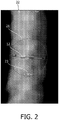
- Fig. 2 illustrates an embodiment of the caliper of the invention.
- the caliper 21 is a knot - a planar circle.
- the caliper 21 is used to measure the diameter of a blood vessel 22. After placing the caliper, the length 23 of the diameter of the circle is displayed.
- the size of the caliper 21 is adjusted by rotating a mouse wheel. There are two speeds for changing the size of the caliper 21. When the user presses and rotates the mouse wheel, the speed is high. The size of the caliper 21 changes in steps of 4 mm. When the user rotates the mouse wheel without pressing it, the speed is low and the size of the caliper 21 changes in steps of 0.5 mm.
- the same scaling method with other speeds may be implemented in further embodiments. During this scaling, the center of the circle does not move.
- the user may select any point on the display as the scaling center.
- rotating the mouse wheel will result in scaling the circle.
- the center of the circle translates along the line joining the selected point and the circle center.
- the ratio of the distance between the center of the scaled circle and the selected point to the distance between the center of the circle before scaling and the selected point is equal to the scaling factor.
- the user uses the "drag and drop” operation of the mouse: he/she places the mouse pointer inside the circle, presses a mouse button and then moves the mouse while pressing the mouse button.
- the mouse pointer moves on the screen and “drags” the circle.
- the circle is “dropped”, i.e., released, in its current location.
- the caliper 21 provides more accurate measurements with less manual interaction.
- the user interface 300 comprises a "caliper on” button. After the user presses and activates the caliper by pressing the button, the caliper becomes attached to the mouse pointer. When the user moves the mouse, the mouse pointer and the caliper move accordingly. The user may release the caliper in a desired location by pressing a mouse button.
- the shape of the caliper 21 may be different, e.g., the knot comprised in the caliper 21 may be the edge of a square, an ellipse, a non-planar closed curve topologically equivalent to a circle, or a trefoil knot.
- the knot is determined based on a user input.
- the caliper 21 may be a surface bounded by the knot. Such a surface may be defined, for example, as a union of all intervals whose first end is a pre-defined point on the knot and whose second end is another point on the knot.
- the knot may be mapped by a one-to-one continuous map, whose inverse is also continuous, on a surface. A part of the surface bounded by the mapped knot may be the caliper. All these embodiments illustrate the invention and should not be construed as limiting the scope of the claims.
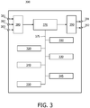
- Fig. 3 schematically shows a block diagram of an exemplary embodiment of the user interface 300 for measuring an object viewed in an image computed from image data, the user interface comprising:
- the exemplary embodiment of the user interface 300 further comprises the following units:
- the first input connector 381 is arranged to receive data coming in from a data storage means such as, but not limited to, a hard disk, a magnetic tape, a flash memory, or an optical disk.
- the second input connector 382 is arranged to receive data coming in from a user input device such as, but not limited to, a mouse or a touch screen.
- the third input connector 383 is arranged to receive data coming in from a user input device such as a keyboard.
- the input connectors 381, 382 and 383 are connected to an input control unit 380.
- the first output connector 391 is arranged to output the data to a data storage means such as a hard disk, a magnetic tape, a flash memory, or an optical disk.
- the second output connector 392 is arranged to output the data to a display device.
- the output connectors 391 and 392 receive the respective data via an output control unit 390.
- the user interface 300 comprises a memory unit 370.
- the user interface 300 is arranged to receive input data from external devices via any of the input connectors 381, 382, and 383 and to store the received input data in the memory unit 370. Loading the input data into the memory unit 370 allows quick access to relevant data portions by the units of the user interface 300.
- the input data may comprise, for example, the image data.
- the memory unit 370 may be implemented by devices such as, but not limited to, a Random Access Memory (RAM) chip, a Read Only Memory (ROM) chip, and/or a hard disk drive and a hard disk.
- the memory unit 370 may be further arranged to store the output data.
- the output data may comprise, for example, data for displaying the caliper 21.
- the memory unit 370 may be also arranged to receive data from and deliver data to the units of the user interface 300 comprising the image unit 310, the deployment unit 320, the scaling unit 330, the translation unit 340, the rotation unit 345, and the caliper unit 350, via a memory bus 375.
- the memory unit 370 is further arranged to make the output data available to external devices via any of the output connectors 391 and 392. Storing data from the units of the user interface 300 in the memory unit 370 may advantageously improve performance of the units of the user interface 300 as well as the rate of transfer of the output data from the units of the user interface 300 to external devices.
- the user interface 300 may comprise no memory unit 370 and no memory bus 375.
- the input data used by the user interface 300 may be supplied by at least one external device, such as an external memory or a processor, connected to the units of the user interface 300.
- the output data produced by the user interface 300 may be supplied to at least one external device, such as an external memory or a processor, connected to the units of the user interface 300.
- the units of the user interface 300 may be arranged to receive the data from each other via internal connections or via a data bus.
- the image unit 310 of the user interface 300 is arranged for visualizing the image data in the image for displaying on a display.
- the tasks to be performed by the image unit 310 include, for example, determining a viewport for displaying the image.
- the skilled person will know typical functions, which can be implemented in embodiments of the image unit 310.
- the view may be computed using, for example, maximum intensity projection (MIP), iso-surface projection (ISP), and direct volume rendering (DVR).
- MIP maximum intensity projection
- ISP iso-surface projection
- DVR direct volume rendering
- MIP a 3D location of maximum intensity along a projection ray is found.
- the ray is cast from a viewing plane.
- the intensity value of the pixel on the viewing plane may be set to the found maximum intensity value along the ray.
- ISP projection rays are terminated when they cross the iso-surface of interest.
- the iso-surface is defined as the level set of the intensity function, i.e. as the set of all voxels having the same intensity value.
- Objects such as iso-surfaces may be identified in the image data and may be used to define objects in model coordinate systems of a graphics processor.
- a graphics pipeline of the graphics processor may be used to compute the view of the objects comprised in the model coordinate systems.
- the graphics pipeline is described in a book by J. D. Foley et al, entitled “Computer graphics: Principles and practice", 2nd Ed., Addison-Wesley, Reading, Massachusetts, USA, 1996 .
- the deployment unit 320 of the user interface 300 is arranged for deploying a caliper 21 in an image data space.
- the caliper is deployed in a pre-defined location of the image data space or in a location specified by the user.
- the deployment unit 320 may be arranged to receive a user input for specifying a caliper 21 of a plurality of calipers for deployment.
- the scaling unit 330 of the user interface 300 is arranged for scaling the caliper 21 by a scaling factor in a direction in the image data space.
- the scaling unit 330 may be arranged to receive a user input from a user input device, such as a keyboard, a mouse, or a trackball, for example, and compute the size of the caliper 21 on the basis of this user input.
- the scaling of the caliper 21 may be isotropic or anisotropic. For example, scaling of the caliper 21 defined by the circle shown in Fig. 2 is isotropic. Scaling of a caliper 21 comprising an ellipse may be anisotropic and may occur in the direction of an axis of the ellipse.
- Scaling of a 3D caliper 21 may occur in a plurality of directions.
- a plurality of scaling factors may be determined, e.g., one scaling factor for each scaling direction.
- the mode of scaling may be selectable and may be determined by the user.
- the translation unit 340 of the user interface 300 is arranged for translating the caliper 21 in the image data space.
- the translation unit 340 may be arranged to receive a user input from a user input device, such as a keyboard, a mouse, or a trackball, for example, and to compute the translated location of the caliper 21 on the basis of this user input.
- the translation vectors are substantially parallel to the viewing plane.
- translations in all directions in the image data space are implemented.
- the user may also be able to zoom in and out the caliper 21, when a perspective projection technique is used by the image unit 310 to compute the view of the region of the image data space.
- the caliper unit 350 of the user interface is arranged for visualizing the caliper 21 in the image.
- the caliper unit 350 is arranged to obtain data from the deployment unit 320, scaling unit 330, and translation unit 340. Based on this data, the caliper unit 350 is further arranged to compute the image of the caliper 21 in the image data space for visualizing the caliper 21 in the image.
- the caliper unit 350 may be a component of, or may receive data from, the image unit 310 to determine how the caliper should be located in the 3D image data space.
- the caliper unit 350 may receive the depth value of a pixel displayed at the center of the circle to compute the size of the caliper at this depth in the perspective projection.
- the user interface 300 comprises a rotation unit 345 for rotating the caliper 21 in the image data space. Any number of rotation axes may be used by the rotation unit 345. For each rotation, a rotation axis and/or angle are determined by the user, and user input data specifying the rotation axis and/or angle is obtained by the rotation unit 345.
- a rotation axis may be one of the three Cartesian axes of a reference system in the image data space. Alternatively, a rotation axis may be an axis of the caliper.
- the caliper unit 350 may be arranged to obtain data from the rotation unit 345. Based on this data, the caliper unit 350 may be further arranged to compute the image of the rotated caliper 21 in the image data space for visualizing the caliper 21 in the image.
- the user interface 300 described in the current document may be a valuable tool for assisting a physician in many aspects of her/his job.
- the units of the user interface 300 may be implemented using a processor. Normally, their functions are performed under the control of a software program product. During the execution, the software program product is normally loaded into a memory, like a RAM, and executed from there. The program may be loaded from a background memory, such as a ROM, hard disk, or magnetic and/or optical storage, or may be loaded via a network like the Internet. Optionally, an application-specific integrated circuit may provide the described functionality.
- Fig. 7 shows a flowchart of an exemplary implementation of the method 700 of measuring an object viewed in an image computed from image data.
- the method 700 begins with an image step 710 for visualizing the image data in the image.
- the method 700 continues to a deployment step 720 for deploying a caliper 21 in an image data space.
- the method 700 continues to a caliper step 750 for visualizing the caliper 21 in the image.
- the method 700 allows the user to manipulate the caliper.
- a manipulation step 725 comprising a scaling step 730 for scaling the caliper 21 by a scaling factor in a direction in the image data space, a translation step 740 for translating the caliper 21 in the image data space, and a rotation step 745 for rotating the caliper 21 in the image data space.
- the method 700 continues to the caliper step 750.
- the method 700 returns to the manipulation step 725 for more manipulation of the caliper in the image data space, or terminates.
- the caliper 21 of the method 700 comprises a knot for measuring the object. The object is measured based on the scaling factor used for scaling the caliper.
- steps of the method 700 of the current invention may be combined into one step.
- a step of the method 700 of the current invention may be split into a plurality of steps.
- Fig. 8 schematically shows an exemplary embodiment of the image acquisition apparatus 800 employing the user interface 300, said image acquisition apparatus 800 comprising a CT image acquisition unit 810 connected via an internal connection with the user interface 300, an input connector 801, and an output connector 802.
- This arrangement advantageously increases the capabilities of the image acquisition apparatus 800, providing said image acquisition apparatus 800 with advantageous capabilities of the user interface 300.
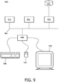
- Fig. 9 schematically shows an exemplary embodiment of the workstation 900.
- the workstation comprises a second user interface bus 901.
- a processor 910, a memory 920, a disk input/output (I/O) adapter 930, and a second user interface (UI) 940 are operatively connected to the second user interface bus 901.
- a disk storage device 931 is operatively coupled to the disk I/O adapter 930.
- a keyboard 941, a mouse 942, and a display 943 are operatively coupled to the UI 940.
- the user interface 300 of the invention implemented as a computer program, is stored in the disk storage device 931.
- the workstation 900 is arranged to load the program and input data into memory 920 and execute the program on the processor 910.
- the user can input information to the workstation 900 using the keyboard 941 and/or the mouse 942.
- the workstation is arranged to output information to the display device 943 and/or to the disk 931.
- the skilled person will understand that there are numerous other embodiments of the workstation 900 known in the art and that the present embodiment serves the purpose of illustrating the invention which is only limited by the appended claims.
Landscapes
- Engineering & Computer Science (AREA)
- Physics & Mathematics (AREA)
- General Physics & Mathematics (AREA)
- Theoretical Computer Science (AREA)
- Computer Vision & Pattern Recognition (AREA)
- General Health & Medical Sciences (AREA)
- Health & Medical Sciences (AREA)
- Medical Informatics (AREA)
- Nuclear Medicine, Radiotherapy & Molecular Imaging (AREA)
- Radiology & Medical Imaging (AREA)
- Quality & Reliability (AREA)
- Processing Or Creating Images (AREA)
- Apparatus For Radiation Diagnosis (AREA)
- Measuring And Recording Apparatus For Diagnosis (AREA)
Description
- The invention relates to the field of medical imaging and, more specifically, to measuring structures viewed in medical images.
- Clinical applications traditionally involve image data, which needs to be analyzed and interpreted. Based on interpretation of the image data, a physician can make a diagnosis and advise a treatment suitable for a patient. Proper interpretation of an image computed from the image data often requires measuring objects describing anatomical and pathological structures visualized in the image. To this end, the physician needs a tool which allows her/him to assess the diameter of a blood vessel or the size of a tumor, for example. In most applications, to measure an object, the user determines two points in a three-dimensional image data space, hereinafter referred to as 3D points, and the application is arranged to calculate the distance between these 3D points. A line segment connecting the determined 3D points may be displayed.
- Unfortunately, it is not always possible to accurately determine two points on the surface of a measured structure such as a blood vessel, for example. This is because the surface, on which a point is to be selected, is typically perpendicular to the viewing plane.
-
Fig. 1 illustrates the problem of the prior art method. The goal is to measure the diameter of theblood vessel 11. Two points, connected by aline segment 12, are selected on the two opposite edges in the rendered image of the blood vessel. The diameter of thevessel 11 is typically underestimated, as shown on the zoomed-invessel segment 13. - To overcome this problem, in current applications, the user needs to make edges in the rendered image of the blood vessel clearly visible. This is achieved by positioning the blood vessel in the image to make the first edge visible and determining the first point. Then the user repositions the vessel to make the second edge visible and determines the second point. Alternatively, the user can zoom in the vessel, select the two points, and zoom out the vessel to its original position. Unfortunately, these operations require extra user interaction to measure the blood vessel. A further problem is that the drawn line segment may be not aligned perpendicularly to the vessel axis, as it should be.
- To measure objects visualized in two-dimensional images, an on-screen caliper may be used. An implementation of such a caliper is offered on-line by Inico at http://www.iconico.com/caliper/index.aspx, retrieved July 12, 2007. This caliper, however, obstructs the view of structures visualized in an image.
-
WO 2005/116923 A1 also describes techniques for measuring objects in an image. A measurement tool is provided for measuring lengths of image objects in pixel units: to calculate the corresponding physical lengths, a scaling factor, sometimes referred to as a calibration factor, must be determined beforehand. Said scaling factor expresses the size of pixels or voxels in physical length units and can be either manually entered by the user as a numerical value, or is determined from markers of known physical dimensions, e.g. anatomical features or extraneous objects such as screws or rulers. Once the scaling factor is known, every user-selected feature can be measured automatically based on conventional segmentation techniques. - It would be advantageous to have a system that requires less user interaction without compromising accuracy of the measurement
- This desired advantage is achieved by the invention by means of a user interface, an image acquisition apparatus, a workstation, a method and a computer program product as set out in the appended claims.
- The invention comprises inter alia using a caliper deployed in an image data space, such that the caliper comprises a knot for measuring an object.
- The phrase "the caliper comprises a knot" should be interpreted to mean that the knot is a distinguishable component of the caliper. The knot may be a circle - the simplest knot. The caliper may be the circle, a disc defined by the circle, or a spherical cap of a given curvature bordered by the circle. An introduction to the mathematics of knots can be found in an article published at http://en.wikipedia.org/wiki/Knot_ (mathematics), retrieved July 12, 2007. It is also possible that the caliper comprises a knot for measuring the object and another structural or functional element, e.g., the caliper may comprise a circle, a line segment with both ends on the circle, and/or a rotation axis perpendicular to the plane of the circle and crossing this plane at a point inside the circle. In another embodiment, the caliper may comprise two concentric circles of different radiuses.
- The caliper comprising the knot, which determines the shape of the caliper, is a simple reference object of known geometry and size. Looking at the image data and the caliper visualized in the image, the user may easily place the caliper in the image data space and adjust the size of the caliper to match the size of the measured object. Unlike the prior art methods, which are based on selecting two points and measuring the distance between them, there is no need to change the view of the image data in order to place and/or adjust the size of the caliper. Therefore, the caliper of the invention typically reduces the amount of manual interactions needed to measure the object. Advantageously, the caliper of the invention may improve the visual experience of the user.
- The skilled person will appreciate that the user interface may be applied to view reports comprising multidimensional image data, e.g., 2-dimensional, 3-dimensional, or 4-dimensional images, acquired by various acquisition modalities such as, but not limited to, standard X-ray Imaging, Computed Tomography (CT), Magnetic Resonance Imaging (MRI), Ultrasound (US), Positron Emission Tomography (PET), Single Photon Emission Computed Tomography (SPECT), Digital Tomosynthesis, and Nuclear Medicine (NM).
- These and other aspects of the invention will become apparent from and will be elucidated with respect to the implementations and embodiments described hereinafter and with reference to the accompanying drawings, wherein:
-
Fig. 1 illustrates the problem of the prior art caliper; -
Fig. 2 illustrates an embodiment of the caliper of the invention; -
Fig. 3 schematically shows a block diagram of an exemplary embodiment of the user interface; -
Fig. 4 illustrates multiple measurements of the same object; -
Fig. 5 illustrates using a caliper for measuring the diameter of the base of a colon polyp; -
Fig. 6 schematically illustrates an implementation of the circular caliper in the perspective and parallel projections; -
Fig. 7 shows a flowchart of an exemplary implementation of the method; -
Fig. 8 schematically shows an exemplary embodiment of the image acquisition apparatus; and -
Fig. 9 schematically shows an exemplary embodiment of the workstation. - Identical reference numerals are used to denote similar parts throughout the Figures.
-
Fig. 2 illustrates an embodiment of the caliper of the invention. Here thecaliper 21 is a knot - a planar circle. Thecaliper 21 is used to measure the diameter of ablood vessel 22. After placing the caliper, thelength 23 of the diameter of the circle is displayed. - In an embodiment of the user interface, the size of the
caliper 21 is adjusted by rotating a mouse wheel. There are two speeds for changing the size of thecaliper 21. When the user presses and rotates the mouse wheel, the speed is high. The size of thecaliper 21 changes in steps of 4 mm. When the user rotates the mouse wheel without pressing it, the speed is low and the size of thecaliper 21 changes in steps of 0.5 mm. The same scaling method with other speeds may be implemented in further embodiments. During this scaling, the center of the circle does not move. - Alternatively, in an embodiment, the user may select any point on the display as the scaling center. When the selected point is not at the center of the circle, rotating the mouse wheel will result in scaling the circle. The center of the circle translates along the line joining the selected point and the circle center. The ratio of the distance between the center of the scaled circle and the selected point to the distance between the center of the circle before scaling and the selected point is equal to the scaling factor.
- To translate the circle in the horizontal direction, the user uses the "drag and drop" operation of the mouse: he/she places the mouse pointer inside the circle, presses a mouse button and then moves the mouse while pressing the mouse button. The mouse pointer moves on the screen and "drags" the circle. When the user releases the mouse button, the circle is "dropped", i.e., released, in its current location. The
caliper 21 provides more accurate measurements with less manual interaction. - In an embodiment, the
user interface 300 comprises a "caliper on" button. After the user presses and activates the caliper by pressing the button, the caliper becomes attached to the mouse pointer. When the user moves the mouse, the mouse pointer and the caliper move accordingly. The user may release the caliper in a desired location by pressing a mouse button. - The skilled person will understand that there are many possible embodiments of the
caliper 21. For example, the shape of thecaliper 21 may be different, e.g., the knot comprised in thecaliper 21 may be the edge of a square, an ellipse, a non-planar closed curve topologically equivalent to a circle, or a trefoil knot. In an embodiment, the knot is determined based on a user input. Further, thecaliper 21 may be a surface bounded by the knot. Such a surface may be defined, for example, as a union of all intervals whose first end is a pre-defined point on the knot and whose second end is another point on the knot. Alternatively, the knot may be mapped by a one-to-one continuous map, whose inverse is also continuous, on a surface. A part of the surface bounded by the mapped knot may be the caliper. All these embodiments illustrate the invention and should not be construed as limiting the scope of the claims. -
Fig. 3 schematically shows a block diagram of an exemplary embodiment of theuser interface 300 for measuring an object viewed in an image computed from image data, the user interface comprising: - an
image unit 310 for visualizing the image data in the image for displaying on a display; - a
deployment unit 320 for deploying acaliper 21 in an image data space; - a
scaling unit 330 for scaling thecaliper 21 by a scaling factor in a direction in the image data space; - a
translation unit 340 for translating thecaliper 21 in the image data space; and - a
caliper unit 350 for visualizing the caliper in the image;
wherein thecaliper 21 comprises a knot for measuring the object and wherein the object is measured based on the scaling factor. - The exemplary embodiment of the
user interface 300 further comprises the following units: - a
rotation unit 345 for rotating thecaliper 21 in the image data space; and - a
memory unit 370 for storing data. - In an embodiment of the
user interface 300, there are threeinput connectors first input connector 381 is arranged to receive data coming in from a data storage means such as, but not limited to, a hard disk, a magnetic tape, a flash memory, or an optical disk. Thesecond input connector 382 is arranged to receive data coming in from a user input device such as, but not limited to, a mouse or a touch screen. Thethird input connector 383 is arranged to receive data coming in from a user input device such as a keyboard. Theinput connectors input control unit 380. - In an embodiment of the
user interface 300, there are twooutput connectors first output connector 391 is arranged to output the data to a data storage means such as a hard disk, a magnetic tape, a flash memory, or an optical disk. Thesecond output connector 392 is arranged to output the data to a display device. Theoutput connectors output control unit 390. - The skilled person will understand that there are many ways to connect input devices to the
input connectors output connectors user interface 300. These ways comprise, but are not limited to, a wired and a wireless connection, a digital network such as, but not limited to, a Local Area Network (LAN) and a Wide Area Network (WAN), the Internet, a digital telephone network, and an analog telephone network. - In an embodiment of the
user interface 300, theuser interface 300 comprises amemory unit 370. Theuser interface 300 is arranged to receive input data from external devices via any of theinput connectors memory unit 370. Loading the input data into thememory unit 370 allows quick access to relevant data portions by the units of theuser interface 300. The input data may comprise, for example, the image data. Thememory unit 370 may be implemented by devices such as, but not limited to, a Random Access Memory (RAM) chip, a Read Only Memory (ROM) chip, and/or a hard disk drive and a hard disk. Thememory unit 370 may be further arranged to store the output data. The output data may comprise, for example, data for displaying thecaliper 21. Thememory unit 370 may be also arranged to receive data from and deliver data to the units of theuser interface 300 comprising theimage unit 310, thedeployment unit 320, thescaling unit 330, thetranslation unit 340, therotation unit 345, and thecaliper unit 350, via amemory bus 375. Thememory unit 370 is further arranged to make the output data available to external devices via any of theoutput connectors user interface 300 in thememory unit 370 may advantageously improve performance of the units of theuser interface 300 as well as the rate of transfer of the output data from the units of theuser interface 300 to external devices. - Alternatively, the
user interface 300 may comprise nomemory unit 370 and nomemory bus 375. The input data used by theuser interface 300 may be supplied by at least one external device, such as an external memory or a processor, connected to the units of theuser interface 300. Similarly, the output data produced by theuser interface 300 may be supplied to at least one external device, such as an external memory or a processor, connected to the units of theuser interface 300. The units of theuser interface 300 may be arranged to receive the data from each other via internal connections or via a data bus. - The
image unit 310 of theuser interface 300 is arranged for visualizing the image data in the image for displaying on a display. The tasks to be performed by theimage unit 310 include, for example, determining a viewport for displaying the image. The skilled person will know typical functions, which can be implemented in embodiments of theimage unit 310. - There are many ways of computing a view of a 3D region of image data space. The view may be computed using, for example, maximum intensity projection (MIP), iso-surface projection (ISP), and direct volume rendering (DVR). In MIP, a 3D location of maximum intensity along a projection ray is found. The ray is cast from a viewing plane. The intensity value of the pixel on the viewing plane may be set to the found maximum intensity value along the ray. In ISP, projection rays are terminated when they cross the iso-surface of interest. The iso-surface is defined as the level set of the intensity function, i.e. as the set of all voxels having the same intensity value. More information on MIP and ISP can be found in a book by Barthold Lichtenbelt, Randy Crane, and Shaz Naqvi, entitled "Introduction to Volume Rendering", published by Hewlett-Packard Professional Books, Prentice Hall; Bk&CD-Rom edition (1998). In DVR, a transfer function assigns a renderable property, such as opacity, to intensity values comprised in the image data. An implementation of DVR is described in an article by T. He et al. entitled "Generation of Transfer Functions with Stochastic Search Techniques" in Proceedings of IEEE Visualization, pages 227- 234, 1996.
- Objects such as iso-surfaces may be identified in the image data and may be used to define objects in model coordinate systems of a graphics processor. A graphics pipeline of the graphics processor may be used to compute the view of the objects comprised in the model coordinate systems. The graphics pipeline is described in a book by J. D. Foley et al, entitled "Computer graphics: Principles and practice", 2nd Ed., Addison-Wesley, Reading, Massachusetts, USA, 1996.
- The skilled person will understand that there are many methods that may be employed for computing a view of a 3D region of image data space from the image data. The choice of the method of computing the view of the 3D region of the image data space does not limit the scope of the claims.
- The
deployment unit 320 of theuser interface 300 is arranged for deploying acaliper 21 in an image data space. The caliper is deployed in a pre-defined location of the image data space or in a location specified by the user. Optionally, thedeployment unit 320 may be arranged to receive a user input for specifying acaliper 21 of a plurality of calipers for deployment. - The
scaling unit 330 of theuser interface 300 is arranged for scaling thecaliper 21 by a scaling factor in a direction in the image data space. Thescaling unit 330 may be arranged to receive a user input from a user input device, such as a keyboard, a mouse, or a trackball, for example, and compute the size of thecaliper 21 on the basis of this user input. The scaling of thecaliper 21 may be isotropic or anisotropic. For example, scaling of thecaliper 21 defined by the circle shown inFig. 2 is isotropic. Scaling of acaliper 21 comprising an ellipse may be anisotropic and may occur in the direction of an axis of the ellipse. Scaling of a3D caliper 21 may occur in a plurality of directions. Optionally, a plurality of scaling factors may be determined, e.g., one scaling factor for each scaling direction. Optionally, the mode of scaling may be selectable and may be determined by the user. - The
translation unit 340 of theuser interface 300 is arranged for translating thecaliper 21 in the image data space. Thetranslation unit 340 may be arranged to receive a user input from a user input device, such as a keyboard, a mouse, or a trackball, for example, and to compute the translated location of thecaliper 21 on the basis of this user input. In an embodiment, the translation vectors are substantially parallel to the viewing plane. In another embodiment, translations in all directions in the image data space are implemented. Optionally, the user may also be able to zoom in and out thecaliper 21, when a perspective projection technique is used by theimage unit 310 to compute the view of the region of the image data space. - The
caliper unit 350 of the user interface is arranged for visualizing thecaliper 21 in the image. Thecaliper unit 350 is arranged to obtain data from thedeployment unit 320, scalingunit 330, andtranslation unit 340. Based on this data, thecaliper unit 350 is further arranged to compute the image of thecaliper 21 in the image data space for visualizing thecaliper 21 in the image. Optionally, thecaliper unit 350 may be a component of, or may receive data from, theimage unit 310 to determine how the caliper should be located in the 3D image data space. For example, thecaliper unit 350 may receive the depth value of a pixel displayed at the center of the circle to compute the size of the caliper at this depth in the perspective projection. - In an embodiment, the
user interface 300 comprises arotation unit 345 for rotating thecaliper 21 in the image data space. Any number of rotation axes may be used by therotation unit 345. For each rotation, a rotation axis and/or angle are determined by the user, and user input data specifying the rotation axis and/or angle is obtained by therotation unit 345. A rotation axis may be one of the three Cartesian axes of a reference system in the image data space. Alternatively, a rotation axis may be an axis of the caliper. Thecaliper unit 350 may be arranged to obtain data from therotation unit 345. Based on this data, thecaliper unit 350 may be further arranged to compute the image of the rotatedcaliper 21 in the image data space for visualizing thecaliper 21 in the image. -
Fig. 4 illustrates multiple measurements of the same object -vertebra 41. Using thecaliper 21 the user may easily measure various parameters of thevertebrae 41. -
Fig. 5 illustrates using a caliper for measuring the diameter of the base of a colon polyp. The caliper visualization is performed in an unfoldedcube projection 51 with strong perspective deformation.Fig. 5 shows that the implementation of the caliper properly describes images with perspective projections. The size of the caliper parts 21-1 and 21-2 changes at different depths. The shape of the circular caliper needs to deform accordingly. Thus, the projection of the caliper in a perspective is not a circle. This feature is very useful for virtual colonoscopy users. -
Fig. 6 schematically illustrates an implementation of thecircular caliper 21 in a perspective and parallel projection. Given a 2D location in the viewing plane, typically the location of the mouse pointer, a 3D location P in the image data space is determined by theimage unit 310, for example. The 2D location represents the center of the circle of animage 22 of thecircular caliper 21. For a perspective projection, shown in thetop image 61, the actual radius of thecircle 22 for displaying on a display is determined based on the 3D location P, namely, based on the distance of the 3D location P from the viewer position point VP. For an orthographic projection, the radius of theactual circle 21 is identical to the radius of the displayedcircle 22, irrespective of the 3D location P. - The skilled person will understand that other embodiments of the
user interface 300 are also possible. It is possible, among other things, to redefine the units of theuser interface 300 and to redistribute their functions. Although the described embodiments apply to medical images, other applications of theuser interface 300, outside the medical domain, are also possible. - The skilled person will further recognize that the
user interface 300 described in the current document may be a valuable tool for assisting a physician in many aspects of her/his job. - The units of the
user interface 300 may be implemented using a processor. Normally, their functions are performed under the control of a software program product. During the execution, the software program product is normally loaded into a memory, like a RAM, and executed from there. The program may be loaded from a background memory, such as a ROM, hard disk, or magnetic and/or optical storage, or may be loaded via a network like the Internet. Optionally, an application-specific integrated circuit may provide the described functionality. -
Fig. 7 shows a flowchart of an exemplary implementation of themethod 700 of measuring an object viewed in an image computed from image data. Themethod 700 begins with animage step 710 for visualizing the image data in the image. After theimage step 710, themethod 700 continues to adeployment step 720 for deploying acaliper 21 in an image data space. After thedeployment step 720, themethod 700 continues to acaliper step 750 for visualizing thecaliper 21 in the image. After the caliper step, themethod 700 allows the user to manipulate the caliper. This is achieved in amanipulation step 725 comprising a scalingstep 730 for scaling thecaliper 21 by a scaling factor in a direction in the image data space, atranslation step 740 for translating thecaliper 21 in the image data space, and arotation step 745 for rotating thecaliper 21 in the image data space. After themanipulation step 725, themethod 700 continues to thecaliper step 750. After thecaliper step 750, themethod 700 returns to themanipulation step 725 for more manipulation of the caliper in the image data space, or terminates. Thecaliper 21 of themethod 700 comprises a knot for measuring the object. The object is measured based on the scaling factor used for scaling the caliper. - The skilled person may change the order of some steps or perform some steps concurrently using threading models, multi-processor systems or multiple processes without departing from the scope of the invention as recited in the appended claims. Optionally, two or more steps of the
method 700 of the current invention may be combined into one step. Optionally, a step of themethod 700 of the current invention may be split into a plurality of steps. -
Fig. 8 schematically shows an exemplary embodiment of theimage acquisition apparatus 800 employing theuser interface 300, saidimage acquisition apparatus 800 comprising a CTimage acquisition unit 810 connected via an internal connection with theuser interface 300, aninput connector 801, and anoutput connector 802. This arrangement advantageously increases the capabilities of theimage acquisition apparatus 800, providing saidimage acquisition apparatus 800 with advantageous capabilities of theuser interface 300. -
Fig. 9 schematically shows an exemplary embodiment of theworkstation 900. The workstation comprises a seconduser interface bus 901. Aprocessor 910, amemory 920, a disk input/output (I/O)adapter 930, and a second user interface (UI) 940 are operatively connected to the seconduser interface bus 901. Adisk storage device 931 is operatively coupled to the disk I/O adapter 930. Akeyboard 941, amouse 942, and adisplay 943 are operatively coupled to theUI 940. Theuser interface 300 of the invention, implemented as a computer program, is stored in thedisk storage device 931. Theworkstation 900 is arranged to load the program and input data intomemory 920 and execute the program on theprocessor 910. The user can input information to theworkstation 900 using thekeyboard 941 and/or themouse 942. The workstation is arranged to output information to thedisplay device 943 and/or to thedisk 931. The skilled person will understand that there are numerous other embodiments of theworkstation 900 known in the art and that the present embodiment serves the purpose of illustrating the invention which is only limited by the appended claims. - It should be noted that the above-mentioned embodiments illustrate rather than limit the invention and that those skilled in the art will be able to design alternative embodiments without departing from the scope of the appended claims. In the claims, any reference signs placed between parentheses shall not be construed as limiting the claim. The word "comprising" does not exclude the presence of elements or steps not listed in a claim or in the description. The word "a" or "an" preceding an element does not exclude the presence of a plurality of such elements. The invention can be implemented by means of hardware comprising several distinct elements and by means of a programmed computer. In the user interface claims enumerating several units, several of these units can be embodied by one and the same item of hardware or software. The usage of the words first, second and third, etc., does not indicate any ordering. These words are to be interpreted as names.
Claims (12)
- A user interface (300) for measuring an object viewed in an image computed from image data, the user interface comprising:- an image unit (310) for visualizing the image data in the image for displaying on a display;- a deployment unit (320) for deploying a caliper (21) in an image data space, wherein the caliper (21) comprises a knot for measuring the object;- a scaling unit (330) for scaling the caliper (21) by a scaling factor in a direction in the image data space, the scaling comprising adjusting a size of the caliper in the image data space, wherein the scaling unit is arranged to receive a user input from a user input device, and compute the size of the caliper on the basis of this user input, and wherein the scaling unit has a selectable mode of scaling, the scaling being selectable between at least isotropic scaling and anisotropic scaling;- a translation unit (340) for translating the caliper (21) in the image data space; and- a caliper unit (350) for visualizing the caliper (21) in the image;
wherein the object is measured based on the scaling factor. - A user interface as claimed in claim 1, wherein the mode of scaling is user-selectable.
- A user interface as claimed in claim 1, wherein
in the case that the caliper comprises a circle, the mode of scaling is selected to be isotropic; and
in the case the caliper comprises an ellipse, the mode of scaling is selected to be anisotropic. - A user interface as claimed in any preceding claim, further comprising a rotation unit (345) for rotating the caliper (21) in the image data space.
- A user interface as claimed in any preceding claim, wherein the knot is an unknot and is substantially planar.
- A user interface as claimed in claim 5, wherein the knot is a circle.
- A user interface as claimed in claim 1, wherein the image data and the caliper are rendered using the perspective projection method.
- A user interface as claimed in claim 1, for measuring the diameter of a blood vessel.
- An image acquisition apparatus (800) comprising a user interface (300) as claimed in claim 1.
- A workstation (900) comprising a user interface (300) as claimed in claim 1.
- A method (700) of measuring an object viewed in an image computed from image data, the method comprising:- an image step (710) for visualizing the image data in the image for displaying on a display;- a deployment step (720) for deploying a caliper (21) in an image data space, wherein the caliper (21) comprises a knot for measuring the object;- a scaling step (730) for scaling the caliper (21) by a scaling factor in a direction in the image data space, wherein the scaling step is arranged to receive a user input from a user input device, and compute the size of the caliper on the basis of this user input, and wherein the scaling unit has a selectable mode of scaling, the scaling being selectable between at least isotropic scaling and anisotropic scaling;- a translation step (740) for translating the caliper (21) in the image data space; and- a caliper step (750) for visualizing the caliper (21) in the image;
wherein the object is measured based on the scaling factor. - A computer program product to be loaded by a computer arrangement, comprising instructions for measuring an object viewed in an image computed from image data, the computer arrangement comprising a processing unit and a memory, the computer program product, after being loaded, providing said processing unit with the capability to carry out the steps of the method according to claim 11.
Priority Applications (1)
| Application Number | Priority Date | Filing Date | Title |
|---|---|---|---|
| EP08807533.8A EP2191442B1 (en) | 2007-09-17 | 2008-09-04 | A caliper for measuring objects in an image |
Applications Claiming Priority (3)
| Application Number | Priority Date | Filing Date | Title |
|---|---|---|---|
| EP07116530 | 2007-09-17 | ||
| EP08807533.8A EP2191442B1 (en) | 2007-09-17 | 2008-09-04 | A caliper for measuring objects in an image |
| PCT/IB2008/053580 WO2009037611A1 (en) | 2007-09-17 | 2008-09-04 | A caliper for measuring objects in an image |
Publications (2)
| Publication Number | Publication Date |
|---|---|
| EP2191442A1 EP2191442A1 (en) | 2010-06-02 |
| EP2191442B1 true EP2191442B1 (en) | 2019-01-02 |
Family
ID=40130557
Family Applications (1)
| Application Number | Title | Priority Date | Filing Date |
|---|---|---|---|
| EP08807533.8A Active EP2191442B1 (en) | 2007-09-17 | 2008-09-04 | A caliper for measuring objects in an image |
Country Status (5)
| Country | Link |
|---|---|
| US (1) | US9965838B2 (en) |
| EP (1) | EP2191442B1 (en) |
| CN (1) | CN101802868B (en) |
| RU (1) | RU2491637C2 (en) |
| WO (1) | WO2009037611A1 (en) |
Families Citing this family (16)
| Publication number | Priority date | Publication date | Assignee | Title |
|---|---|---|---|---|
| US9292187B2 (en) | 2004-11-12 | 2016-03-22 | Cognex Corporation | System, method and graphical user interface for displaying and controlling vision system operating parameters |
| CN101802871B (en) * | 2007-09-17 | 2012-09-05 | 皇家飞利浦电子股份有限公司 | A caliper for measuring objects in an image |
| RU2491637C2 (en) | 2007-09-17 | 2013-08-27 | Конинклейке Филипс Электроникс Н.В. | Thickness gauge for measuring image objects |
| US8897517B2 (en) * | 2008-12-23 | 2014-11-25 | Koninklijke Philips N.V. | Imaging system with reporting function and method of operation thereof |
| GB2475722B (en) * | 2009-11-30 | 2011-11-02 | Mirada Medical | Measurement system for medical images |
| GB2489709B (en) * | 2011-04-05 | 2013-07-31 | Mirada Medical Ltd | Measurement system for medical images |
| US8556816B2 (en) * | 2011-05-27 | 2013-10-15 | Samsung Medison Co., Ltd. | Providing a measuring item candidate group for measuring size of a target object in an ultrasound system |
| JP5907780B2 (en) * | 2012-04-02 | 2016-04-26 | 富士フイルム株式会社 | Ultrasonic diagnostic equipment |
| US9911203B2 (en) * | 2013-10-02 | 2018-03-06 | Given Imaging Ltd. | System and method for size estimation of in-vivo objects |
| JP6134985B2 (en) * | 2014-07-31 | 2017-05-31 | 富士フイルム株式会社 | Curve correction apparatus and method, and program |
| WO2016044465A1 (en) * | 2014-09-16 | 2016-03-24 | Sirona Dental, Inc. | Methods, systems, apparatuses, and computer programs for processing tomographic images |
| CN106528517A (en) * | 2016-11-01 | 2017-03-22 | 深圳市方直科技股份有限公司 | Examination question locating and adjusting method and system |
| US10395382B2 (en) * | 2016-12-30 | 2019-08-27 | Biosense Webster (Israel) Ltd. | Visualization of distances on an electroanatomical map |
| US10102665B2 (en) * | 2016-12-30 | 2018-10-16 | Biosense Webster (Israel) Ltd. | Selecting points on an electroanatomical map |
| CN106846252B (en) * | 2017-02-09 | 2019-11-15 | 深圳市医诺智能科技发展有限公司 | A kind of the anisotropy Zoom method and its system of image target area |
| CN114459397B (en) * | 2022-03-01 | 2024-02-20 | 公安部第一研究所 | CT image size measuring method |
Family Cites Families (15)
| Publication number | Priority date | Publication date | Assignee | Title |
|---|---|---|---|---|
| JPH0542134A (en) | 1991-08-20 | 1993-02-23 | Hitachi Ltd | Three-dimensional image processing method |
| CA2161126C (en) | 1993-04-22 | 2007-07-31 | Waldean A. Schulz | System for locating relative positions of objects |
| JP2000139920A (en) * | 1998-11-06 | 2000-05-23 | Matsushita Electric Ind Co Ltd | Image diagnosis device |
| US6278767B1 (en) | 1999-04-28 | 2001-08-21 | General Electric Company | Methods for measuring curved distances on 3D and MIP images |
| US7113617B2 (en) | 2000-12-12 | 2006-09-26 | Hewlett-Packard Development Company, L.P. | Method of computing sub-pixel Euclidean distance maps |
| US6889113B2 (en) * | 2001-08-23 | 2005-05-03 | Fei Company | Graphical automated machine control and metrology |
| GB0205000D0 (en) | 2002-03-04 | 2002-04-17 | Isis Innovation | Unsupervised data segmentation |
| JP4421203B2 (en) * | 2003-03-20 | 2010-02-24 | 株式会社東芝 | Luminous structure analysis processing device |
| JP2004305236A (en) | 2003-04-01 | 2004-11-04 | Shimadzu Corp | Ultrasonograph |
| US7369638B2 (en) | 2003-07-11 | 2008-05-06 | Siemens Medical Solutions Usa, Inc. | System and method for detecting a protrusion in a medical image |
| CN100527163C (en) | 2004-05-28 | 2009-08-12 | 皇家飞利浦电子股份有限公司 | An image processing apparatus, an imaging system, a computer program and a method for enabling scaling of an object in an image |
| WO2006055251A2 (en) | 2004-11-02 | 2006-05-26 | Metrohealth System | Method and apparatus for determining correlation between spatial coordinates in breast |
| DE102005016258A1 (en) | 2005-04-08 | 2006-10-12 | Siemens Ag | Determining the rectum distance in the colon involves recording at least two image data records for different orientations of patient and determining distance from synopsis of at least two three-dimensional image data records |
| US20070014447A1 (en) | 2005-06-30 | 2007-01-18 | Hubschmann Otakar R | Method for locating brain lesion |
| RU2491637C2 (en) | 2007-09-17 | 2013-08-27 | Конинклейке Филипс Электроникс Н.В. | Thickness gauge for measuring image objects |
-
2008
- 2008-09-04 RU RU2010115351/08A patent/RU2491637C2/en active
- 2008-09-04 WO PCT/IB2008/053580 patent/WO2009037611A1/en active Application Filing
- 2008-09-04 CN CN2008801073572A patent/CN101802868B/en active Active
- 2008-09-04 EP EP08807533.8A patent/EP2191442B1/en active Active
- 2008-09-04 US US12/678,497 patent/US9965838B2/en active Active
Non-Patent Citations (1)
| Title |
|---|
| None * |
Also Published As
| Publication number | Publication date |
|---|---|
| RU2491637C2 (en) | 2013-08-27 |
| RU2010115351A (en) | 2011-10-27 |
| CN101802868A (en) | 2010-08-11 |
| CN101802868B (en) | 2013-07-31 |
| US9965838B2 (en) | 2018-05-08 |
| WO2009037611A1 (en) | 2009-03-26 |
| US20100215245A1 (en) | 2010-08-26 |
| EP2191442A1 (en) | 2010-06-02 |
Similar Documents
| Publication | Publication Date | Title |
|---|---|---|
| EP2191442B1 (en) | A caliper for measuring objects in an image | |
| US9014441B2 (en) | Caliper for measuring objects in an image | |
| EP2074499B1 (en) | 3d connected shadow mouse pointer | |
| EP2486548B1 (en) | Interactive selection of a volume of interest in an image | |
| WO2012063653A1 (en) | Medical image display device and medical image display method | |
| JP6886448B2 (en) | Devices, systems and methods for simulation and visualization of ablation zones | |
| US10540745B2 (en) | Zooming of medical images | |
| JP4856181B2 (en) | Render a view from an image dataset | |
| RU2706231C2 (en) | Visualization of three-dimensional image of anatomical structure | |
| US9142017B2 (en) | TNM classification using image overlays | |
| JP5122650B2 (en) | Path neighborhood rendering | |
| Teistler et al. | Simplifying the exploration of volumetric Images: development of a 3D user interface for the radiologist’s workplace | |
| Zhang et al. | Curvature-vector pair and its application in displaying CT colon data |
Legal Events
| Date | Code | Title | Description |
|---|---|---|---|
| PUAI | Public reference made under article 153(3) epc to a published international application that has entered the european phase |
Free format text: ORIGINAL CODE: 0009012 |
|
| 17P | Request for examination filed |
Effective date: 20100419 |
|
| AK | Designated contracting states |
Kind code of ref document: A1 Designated state(s): AT BE BG CH CY CZ DE DK EE ES FI FR GB GR HR HU IE IS IT LI LT LU LV MC MT NL NO PL PT RO SE SI SK TR |
|
| AX | Request for extension of the european patent |
Extension state: AL BA MK RS |
|
| DAX | Request for extension of the european patent (deleted) | ||
| RAP1 | Party data changed (applicant data changed or rights of an application transferred) |
Owner name: KONINKLIJKE PHILIPS N.V. |
|
| STAA | Information on the status of an ep patent application or granted ep patent |
Free format text: STATUS: EXAMINATION IS IN PROGRESS |
|
| 17Q | First examination report despatched |
Effective date: 20170104 |
|
| REG | Reference to a national code |
Ref country code: DE Ref legal event code: R079 Ref document number: 602008058614 Country of ref document: DE Free format text: PREVIOUS MAIN CLASS: G06T0007000000 Ipc: G06T0007600000 |
|
| GRAP | Despatch of communication of intention to grant a patent |
Free format text: ORIGINAL CODE: EPIDOSNIGR1 |
|
| STAA | Information on the status of an ep patent application or granted ep patent |
Free format text: STATUS: GRANT OF PATENT IS INTENDED |
|
| RIC1 | Information provided on ipc code assigned before grant |
Ipc: G06T 7/60 20060101AFI20180629BHEP |
|
| INTG | Intention to grant announced |
Effective date: 20180717 |
|
| GRAS | Grant fee paid |
Free format text: ORIGINAL CODE: EPIDOSNIGR3 |
|
| GRAA | (expected) grant |
Free format text: ORIGINAL CODE: 0009210 |
|
| STAA | Information on the status of an ep patent application or granted ep patent |
Free format text: STATUS: THE PATENT HAS BEEN GRANTED |
|
| AK | Designated contracting states |
Kind code of ref document: B1 Designated state(s): AT BE BG CH CY CZ DE DK EE ES FI FR GB GR HR HU IE IS IT LI LT LU LV MC MT NL NO PL PT RO SE SI SK TR |
|
| REG | Reference to a national code |
Ref country code: GB Ref legal event code: FG4D |
|
| REG | Reference to a national code |
Ref country code: CH Ref legal event code: EP Ref country code: AT Ref legal event code: REF Ref document number: 1085335 Country of ref document: AT Kind code of ref document: T Effective date: 20190115 |
|
| REG | Reference to a national code |
Ref country code: IE Ref legal event code: FG4D |
|
| REG | Reference to a national code |
Ref country code: DE Ref legal event code: R096 Ref document number: 602008058614 Country of ref document: DE |
|
| REG | Reference to a national code |
Ref country code: DE Ref legal event code: R084 Ref document number: 602008058614 Country of ref document: DE |
|
| REG | Reference to a national code |
Ref country code: GB Ref legal event code: 746 Effective date: 20190325 |
|
| REG | Reference to a national code |
Ref country code: NL Ref legal event code: MP Effective date: 20190102 |
|
| REG | Reference to a national code |
Ref country code: LT Ref legal event code: MG4D |
|
| REG | Reference to a national code |
Ref country code: AT Ref legal event code: MK05 Ref document number: 1085335 Country of ref document: AT Kind code of ref document: T Effective date: 20190102 |
|
| PG25 | Lapsed in a contracting state [announced via postgrant information from national office to epo] |
Ref country code: NL Free format text: LAPSE BECAUSE OF FAILURE TO SUBMIT A TRANSLATION OF THE DESCRIPTION OR TO PAY THE FEE WITHIN THE PRESCRIBED TIME-LIMIT Effective date: 20190102 |
|
| PG25 | Lapsed in a contracting state [announced via postgrant information from national office to epo] |
Ref country code: PT Free format text: LAPSE BECAUSE OF FAILURE TO SUBMIT A TRANSLATION OF THE DESCRIPTION OR TO PAY THE FEE WITHIN THE PRESCRIBED TIME-LIMIT Effective date: 20190502 Ref country code: SE Free format text: LAPSE BECAUSE OF FAILURE TO SUBMIT A TRANSLATION OF THE DESCRIPTION OR TO PAY THE FEE WITHIN THE PRESCRIBED TIME-LIMIT Effective date: 20190102 Ref country code: LT Free format text: LAPSE BECAUSE OF FAILURE TO SUBMIT A TRANSLATION OF THE DESCRIPTION OR TO PAY THE FEE WITHIN THE PRESCRIBED TIME-LIMIT Effective date: 20190102 Ref country code: PL Free format text: LAPSE BECAUSE OF FAILURE TO SUBMIT A TRANSLATION OF THE DESCRIPTION OR TO PAY THE FEE WITHIN THE PRESCRIBED TIME-LIMIT Effective date: 20190102 Ref country code: ES Free format text: LAPSE BECAUSE OF FAILURE TO SUBMIT A TRANSLATION OF THE DESCRIPTION OR TO PAY THE FEE WITHIN THE PRESCRIBED TIME-LIMIT Effective date: 20190102 Ref country code: NO Free format text: LAPSE BECAUSE OF FAILURE TO SUBMIT A TRANSLATION OF THE DESCRIPTION OR TO PAY THE FEE WITHIN THE PRESCRIBED TIME-LIMIT Effective date: 20190402 Ref country code: FI Free format text: LAPSE BECAUSE OF FAILURE TO SUBMIT A TRANSLATION OF THE DESCRIPTION OR TO PAY THE FEE WITHIN THE PRESCRIBED TIME-LIMIT Effective date: 20190102 |
|
| PG25 | Lapsed in a contracting state [announced via postgrant information from national office to epo] |
Ref country code: IS Free format text: LAPSE BECAUSE OF FAILURE TO SUBMIT A TRANSLATION OF THE DESCRIPTION OR TO PAY THE FEE WITHIN THE PRESCRIBED TIME-LIMIT Effective date: 20190502 Ref country code: BG Free format text: LAPSE BECAUSE OF FAILURE TO SUBMIT A TRANSLATION OF THE DESCRIPTION OR TO PAY THE FEE WITHIN THE PRESCRIBED TIME-LIMIT Effective date: 20190402 Ref country code: LV Free format text: LAPSE BECAUSE OF FAILURE TO SUBMIT A TRANSLATION OF THE DESCRIPTION OR TO PAY THE FEE WITHIN THE PRESCRIBED TIME-LIMIT Effective date: 20190102 Ref country code: GR Free format text: LAPSE BECAUSE OF FAILURE TO SUBMIT A TRANSLATION OF THE DESCRIPTION OR TO PAY THE FEE WITHIN THE PRESCRIBED TIME-LIMIT Effective date: 20190403 Ref country code: HR Free format text: LAPSE BECAUSE OF FAILURE TO SUBMIT A TRANSLATION OF THE DESCRIPTION OR TO PAY THE FEE WITHIN THE PRESCRIBED TIME-LIMIT Effective date: 20190102 |
|
| REG | Reference to a national code |
Ref country code: DE Ref legal event code: R097 Ref document number: 602008058614 Country of ref document: DE |
|
| PG25 | Lapsed in a contracting state [announced via postgrant information from national office to epo] |
Ref country code: CZ Free format text: LAPSE BECAUSE OF FAILURE TO SUBMIT A TRANSLATION OF THE DESCRIPTION OR TO PAY THE FEE WITHIN THE PRESCRIBED TIME-LIMIT Effective date: 20190102 Ref country code: IT Free format text: LAPSE BECAUSE OF FAILURE TO SUBMIT A TRANSLATION OF THE DESCRIPTION OR TO PAY THE FEE WITHIN THE PRESCRIBED TIME-LIMIT Effective date: 20190102 Ref country code: SK Free format text: LAPSE BECAUSE OF FAILURE TO SUBMIT A TRANSLATION OF THE DESCRIPTION OR TO PAY THE FEE WITHIN THE PRESCRIBED TIME-LIMIT Effective date: 20190102 Ref country code: AT Free format text: LAPSE BECAUSE OF FAILURE TO SUBMIT A TRANSLATION OF THE DESCRIPTION OR TO PAY THE FEE WITHIN THE PRESCRIBED TIME-LIMIT Effective date: 20190102 Ref country code: EE Free format text: LAPSE BECAUSE OF FAILURE TO SUBMIT A TRANSLATION OF THE DESCRIPTION OR TO PAY THE FEE WITHIN THE PRESCRIBED TIME-LIMIT Effective date: 20190102 Ref country code: DK Free format text: LAPSE BECAUSE OF FAILURE TO SUBMIT A TRANSLATION OF THE DESCRIPTION OR TO PAY THE FEE WITHIN THE PRESCRIBED TIME-LIMIT Effective date: 20190102 Ref country code: RO Free format text: LAPSE BECAUSE OF FAILURE TO SUBMIT A TRANSLATION OF THE DESCRIPTION OR TO PAY THE FEE WITHIN THE PRESCRIBED TIME-LIMIT Effective date: 20190102 |
|
| PLBE | No opposition filed within time limit |
Free format text: ORIGINAL CODE: 0009261 |
|
| STAA | Information on the status of an ep patent application or granted ep patent |
Free format text: STATUS: NO OPPOSITION FILED WITHIN TIME LIMIT |
|
| 26N | No opposition filed |
Effective date: 20191003 |
|
| PG25 | Lapsed in a contracting state [announced via postgrant information from national office to epo] |
Ref country code: SI Free format text: LAPSE BECAUSE OF FAILURE TO SUBMIT A TRANSLATION OF THE DESCRIPTION OR TO PAY THE FEE WITHIN THE PRESCRIBED TIME-LIMIT Effective date: 20190102 |
|
| PG25 | Lapsed in a contracting state [announced via postgrant information from national office to epo] |
Ref country code: TR Free format text: LAPSE BECAUSE OF FAILURE TO SUBMIT A TRANSLATION OF THE DESCRIPTION OR TO PAY THE FEE WITHIN THE PRESCRIBED TIME-LIMIT Effective date: 20190102 |
|
| PG25 | Lapsed in a contracting state [announced via postgrant information from national office to epo] |
Ref country code: MC Free format text: LAPSE BECAUSE OF FAILURE TO SUBMIT A TRANSLATION OF THE DESCRIPTION OR TO PAY THE FEE WITHIN THE PRESCRIBED TIME-LIMIT Effective date: 20190102 |
|
| REG | Reference to a national code |
Ref country code: CH Ref legal event code: PL |
|
| PG25 | Lapsed in a contracting state [announced via postgrant information from national office to epo] |
Ref country code: IE Free format text: LAPSE BECAUSE OF NON-PAYMENT OF DUE FEES Effective date: 20190904 Ref country code: LU Free format text: LAPSE BECAUSE OF NON-PAYMENT OF DUE FEES Effective date: 20190904 Ref country code: CH Free format text: LAPSE BECAUSE OF NON-PAYMENT OF DUE FEES Effective date: 20190930 Ref country code: LI Free format text: LAPSE BECAUSE OF NON-PAYMENT OF DUE FEES Effective date: 20190930 |
|
| REG | Reference to a national code |
Ref country code: BE Ref legal event code: MM Effective date: 20190930 |
|
| PG25 | Lapsed in a contracting state [announced via postgrant information from national office to epo] |
Ref country code: BE Free format text: LAPSE BECAUSE OF NON-PAYMENT OF DUE FEES Effective date: 20190930 |
|
| PG25 | Lapsed in a contracting state [announced via postgrant information from national office to epo] |
Ref country code: CY Free format text: LAPSE BECAUSE OF FAILURE TO SUBMIT A TRANSLATION OF THE DESCRIPTION OR TO PAY THE FEE WITHIN THE PRESCRIBED TIME-LIMIT Effective date: 20190102 |
|
| PG25 | Lapsed in a contracting state [announced via postgrant information from national office to epo] |
Ref country code: HU Free format text: LAPSE BECAUSE OF FAILURE TO SUBMIT A TRANSLATION OF THE DESCRIPTION OR TO PAY THE FEE WITHIN THE PRESCRIBED TIME-LIMIT; INVALID AB INITIO Effective date: 20080904 Ref country code: MT Free format text: LAPSE BECAUSE OF FAILURE TO SUBMIT A TRANSLATION OF THE DESCRIPTION OR TO PAY THE FEE WITHIN THE PRESCRIBED TIME-LIMIT Effective date: 20190102 |
|
| PGFP | Annual fee paid to national office [announced via postgrant information from national office to epo] |
Ref country code: GB Payment date: 20230926 Year of fee payment: 16 |
|
| PGFP | Annual fee paid to national office [announced via postgrant information from national office to epo] |
Ref country code: FR Payment date: 20230926 Year of fee payment: 16 |
|
| PGFP | Annual fee paid to national office [announced via postgrant information from national office to epo] |
Ref country code: DE Payment date: 20240926 Year of fee payment: 17 |