EP2190945B1 - Organic radiation-emitting component - Google Patents
Organic radiation-emitting component Download PDFInfo
- Publication number
- EP2190945B1 EP2190945B1 EP08834044A EP08834044A EP2190945B1 EP 2190945 B1 EP2190945 B1 EP 2190945B1 EP 08834044 A EP08834044 A EP 08834044A EP 08834044 A EP08834044 A EP 08834044A EP 2190945 B1 EP2190945 B1 EP 2190945B1
- Authority
- EP
- European Patent Office
- Prior art keywords
- ligand
- radiation
- metal complex
- guanidinate
- component according
- Prior art date
- Legal status (The legal status is an assumption and is not a legal conclusion. Google has not performed a legal analysis and makes no representation as to the accuracy of the status listed.)
- Active
Links
- 239000003446 ligand Substances 0.000 claims abstract description 80
- 150000004696 coordination complex Chemical class 0.000 claims abstract description 17
- 239000011159 matrix material Substances 0.000 claims abstract description 10
- 150000003624 transition metals Chemical class 0.000 claims abstract description 4
- 229910052723 transition metal Inorganic materials 0.000 claims abstract description 3
- 125000004429 atom Chemical group 0.000 claims description 28
- 229910052751 metal Inorganic materials 0.000 claims description 26
- 239000002184 metal Substances 0.000 claims description 25
- ZRALSGWEFCBTJO-UHFFFAOYSA-N anhydrous guanidine Natural products NC(N)=N ZRALSGWEFCBTJO-UHFFFAOYSA-N 0.000 claims description 19
- CHJJGSNFBQVOTG-UHFFFAOYSA-N N-methyl-guanidine Natural products CNC(N)=N CHJJGSNFBQVOTG-UHFFFAOYSA-N 0.000 claims description 13
- SWSQBOPZIKWTGO-UHFFFAOYSA-N dimethylaminoamidine Natural products CN(C)C(N)=N SWSQBOPZIKWTGO-UHFFFAOYSA-N 0.000 claims description 13
- 125000000623 heterocyclic group Chemical group 0.000 claims description 8
- 125000003118 aryl group Chemical group 0.000 claims description 6
- 125000004433 nitrogen atom Chemical group N* 0.000 claims description 6
- 239000000758 substrate Substances 0.000 claims description 6
- 125000002619 bicyclic group Chemical group 0.000 claims description 5
- 229910052741 iridium Inorganic materials 0.000 claims description 4
- 229910052757 nitrogen Inorganic materials 0.000 claims description 4
- 229910052787 antimony Inorganic materials 0.000 claims description 3
- 229910052785 arsenic Inorganic materials 0.000 claims description 3
- 229910052737 gold Inorganic materials 0.000 claims description 3
- 229910052747 lanthanoid Inorganic materials 0.000 claims description 3
- 150000002602 lanthanoids Chemical class 0.000 claims description 3
- 229910052760 oxygen Inorganic materials 0.000 claims description 3
- 229910052698 phosphorus Inorganic materials 0.000 claims description 3
- 229910052697 platinum Inorganic materials 0.000 claims description 3
- 229910052717 sulfur Inorganic materials 0.000 claims description 3
- 229910052799 carbon Inorganic materials 0.000 claims description 2
- 229910052762 osmium Inorganic materials 0.000 claims description 2
- 229910052763 palladium Inorganic materials 0.000 claims description 2
- 229910052702 rhenium Inorganic materials 0.000 claims description 2
- 229910052707 ruthenium Inorganic materials 0.000 claims description 2
- 229910052711 selenium Inorganic materials 0.000 claims description 2
- 229910052709 silver Inorganic materials 0.000 claims description 2
- 239000004215 Carbon black (E152) Substances 0.000 claims 1
- 229930195733 hydrocarbon Natural products 0.000 claims 1
- YMWUJEATGCHHMB-UHFFFAOYSA-N Dichloromethane Chemical compound ClCCl YMWUJEATGCHHMB-UHFFFAOYSA-N 0.000 description 35
- 239000010410 layer Substances 0.000 description 33
- 125000001424 substituent group Chemical group 0.000 description 20
- 239000000725 suspension Substances 0.000 description 17
- -1 metal complex compound Chemical class 0.000 description 15
- 239000000203 mixture Substances 0.000 description 11
- 150000001875 compounds Chemical class 0.000 description 10
- 238000003786 synthesis reaction Methods 0.000 description 9
- XLYOFNOQVPJJNP-UHFFFAOYSA-N water Substances O XLYOFNOQVPJJNP-UHFFFAOYSA-N 0.000 description 9
- WQDUMFSSJAZKTM-UHFFFAOYSA-N Sodium methoxide Chemical compound [Na+].[O-]C WQDUMFSSJAZKTM-UHFFFAOYSA-N 0.000 description 8
- 230000015572 biosynthetic process Effects 0.000 description 8
- 239000012043 crude product Substances 0.000 description 8
- 150000002357 guanidines Chemical class 0.000 description 8
- 239000000243 solution Substances 0.000 description 8
- UYTPUPDQBNUYGX-UHFFFAOYSA-N guanine Chemical compound O=C1NC(N)=NC2=C1N=CN2 UYTPUPDQBNUYGX-UHFFFAOYSA-N 0.000 description 7
- 230000005855 radiation Effects 0.000 description 7
- 150000003254 radicals Chemical class 0.000 description 7
- VQGHOUODWALEFC-UHFFFAOYSA-N 2-phenylpyridine Chemical compound C1=CC=CC=C1C1=CC=CC=N1 VQGHOUODWALEFC-UHFFFAOYSA-N 0.000 description 6
- FVKFHMNJTHKMRX-UHFFFAOYSA-N 3,4,6,7,8,9-hexahydro-2H-pyrimido[1,2-a]pyrimidine Chemical class C1CCN2CCCNC2=N1 FVKFHMNJTHKMRX-UHFFFAOYSA-N 0.000 description 6
- OFBQJSOFQDEBGM-UHFFFAOYSA-N Pentane Chemical compound CCCCC OFBQJSOFQDEBGM-UHFFFAOYSA-N 0.000 description 6
- ZLMJMSJWJFRBEC-UHFFFAOYSA-N Potassium Chemical compound [K] ZLMJMSJWJFRBEC-UHFFFAOYSA-N 0.000 description 6
- 229940083094 guanine derivative acting on arteriolar smooth muscle Drugs 0.000 description 6
- 238000000103 photoluminescence spectrum Methods 0.000 description 6
- 229910052700 potassium Inorganic materials 0.000 description 6
- 239000011591 potassium Substances 0.000 description 6
- 239000002244 precipitate Substances 0.000 description 6
- 125000000129 anionic group Chemical group 0.000 description 5
- HRGDZIGMBDGFTC-UHFFFAOYSA-N platinum(2+) Chemical compound [Pt+2] HRGDZIGMBDGFTC-UHFFFAOYSA-N 0.000 description 5
- 238000003756 stirring Methods 0.000 description 5
- URLKBWYHVLBVBO-UHFFFAOYSA-N Para-Xylene Chemical group CC1=CC=C(C)C=C1 URLKBWYHVLBVBO-UHFFFAOYSA-N 0.000 description 4
- 150000001450 anions Chemical class 0.000 description 4
- 238000001816 cooling Methods 0.000 description 4
- 238000000151 deposition Methods 0.000 description 4
- 238000002347 injection Methods 0.000 description 4
- 239000007924 injection Substances 0.000 description 4
- 238000004519 manufacturing process Methods 0.000 description 4
- 238000000034 method Methods 0.000 description 4
- BASFCYQUMIYNBI-UHFFFAOYSA-N platinum Substances [Pt] BASFCYQUMIYNBI-UHFFFAOYSA-N 0.000 description 4
- 238000002360 preparation method Methods 0.000 description 4
- ZNQVEEAIQZEUHB-UHFFFAOYSA-N 2-ethoxyethanol Chemical compound CCOCCO ZNQVEEAIQZEUHB-UHFFFAOYSA-N 0.000 description 3
- 0 C[*+]N1*(C)(C)CNC1NC Chemical compound C[*+]N1*(C)(C)CNC1NC 0.000 description 3
- LFQSCWFLJHTTHZ-UHFFFAOYSA-N Ethanol Chemical compound CCO LFQSCWFLJHTTHZ-UHFFFAOYSA-N 0.000 description 3
- 230000000052 comparative effect Effects 0.000 description 3
- 230000008021 deposition Effects 0.000 description 3
- 239000002019 doping agent Substances 0.000 description 3
- 239000000706 filtrate Substances 0.000 description 3
- 239000011521 glass Substances 0.000 description 3
- 239000010931 gold Substances 0.000 description 3
- RAXXELZNTBOGNW-UHFFFAOYSA-N imidazole Natural products C1=CNC=N1 RAXXELZNTBOGNW-UHFFFAOYSA-N 0.000 description 3
- 239000000463 material Substances 0.000 description 3
- 230000007935 neutral effect Effects 0.000 description 3
- 125000002524 organometallic group Chemical group 0.000 description 3
- 239000000047 product Substances 0.000 description 3
- 239000011541 reaction mixture Substances 0.000 description 3
- QGJOPFRUJISHPQ-UHFFFAOYSA-N Carbon disulfide Chemical compound S=C=S QGJOPFRUJISHPQ-UHFFFAOYSA-N 0.000 description 2
- RTZKZFJDLAIYFH-UHFFFAOYSA-N Diethyl ether Chemical compound CCOCC RTZKZFJDLAIYFH-UHFFFAOYSA-N 0.000 description 2
- RWSOTUBLDIXVET-UHFFFAOYSA-N Dihydrogen sulfide Chemical compound S RWSOTUBLDIXVET-UHFFFAOYSA-N 0.000 description 2
- MZRVEZGGRBJDDB-UHFFFAOYSA-N N-Butyllithium Chemical compound [Li]CCCC MZRVEZGGRBJDDB-UHFFFAOYSA-N 0.000 description 2
- CTQNGGLPUBDAKN-UHFFFAOYSA-N O-Xylene Chemical compound CC1=CC=CC=C1C CTQNGGLPUBDAKN-UHFFFAOYSA-N 0.000 description 2
- SMWDFEZZVXVKRB-UHFFFAOYSA-N Quinoline Chemical compound N1=CC=CC2=CC=CC=C21 SMWDFEZZVXVKRB-UHFFFAOYSA-N 0.000 description 2
- WYURNTSHIVDZCO-UHFFFAOYSA-N Tetrahydrofuran Chemical compound C1CCOC1 WYURNTSHIVDZCO-UHFFFAOYSA-N 0.000 description 2
- XLOMVQKBTHCTTD-UHFFFAOYSA-N Zinc monoxide Chemical compound [Zn]=O XLOMVQKBTHCTTD-UHFFFAOYSA-N 0.000 description 2
- 125000001931 aliphatic group Chemical group 0.000 description 2
- 230000000903 blocking effect Effects 0.000 description 2
- 125000004432 carbon atom Chemical group C* 0.000 description 2
- 229940125904 compound 1 Drugs 0.000 description 2
- 229940125782 compound 2 Drugs 0.000 description 2
- 229940126214 compound 3 Drugs 0.000 description 2
- 238000002425 crystallisation Methods 0.000 description 2
- 230000008025 crystallization Effects 0.000 description 2
- 125000004122 cyclic group Chemical group 0.000 description 2
- 230000005595 deprotonation Effects 0.000 description 2
- 238000010537 deprotonation reaction Methods 0.000 description 2
- 238000003682 fluorination reaction Methods 0.000 description 2
- JVZRCNQLWOELDU-UHFFFAOYSA-N gamma-Phenylpyridine Natural products C1=CC=CC=C1C1=CC=NC=C1 JVZRCNQLWOELDU-UHFFFAOYSA-N 0.000 description 2
- 230000005525 hole transport Effects 0.000 description 2
- 229910000037 hydrogen sulfide Inorganic materials 0.000 description 2
- GKOZUEZYRPOHIO-UHFFFAOYSA-N iridium atom Chemical compound [Ir] GKOZUEZYRPOHIO-UHFFFAOYSA-N 0.000 description 2
- 239000002346 layers by function Substances 0.000 description 2
- 230000003647 oxidation Effects 0.000 description 2
- 238000007254 oxidation reaction Methods 0.000 description 2
- 238000010992 reflux Methods 0.000 description 2
- 150000003839 salts Chemical class 0.000 description 2
- 238000000859 sublimation Methods 0.000 description 2
- 230000008022 sublimation Effects 0.000 description 2
- 239000000126 substance Substances 0.000 description 2
- 239000008096 xylene Substances 0.000 description 2
- 229910052725 zinc Inorganic materials 0.000 description 2
- 239000011701 zinc Substances 0.000 description 2
- XKGVCEFEHBFGEL-UHFFFAOYSA-N 2,4-difluoro-2-phenyl-1H-pyridine Chemical compound FC1(NC=CC(=C1)F)C1=CC=CC=C1 XKGVCEFEHBFGEL-UHFFFAOYSA-N 0.000 description 1
- ZCUJYXPAKHMBAZ-UHFFFAOYSA-N 2-phenyl-1h-imidazole Chemical compound C1=CNC(C=2C=CC=CC=2)=N1 ZCUJYXPAKHMBAZ-UHFFFAOYSA-N 0.000 description 1
- QTBSBXVTEAMEQO-UHFFFAOYSA-M Acetate Chemical compound CC([O-])=O QTBSBXVTEAMEQO-UHFFFAOYSA-M 0.000 description 1
- CXLCSYINYVAMHH-UHFFFAOYSA-N C(CN1)CN2C1NCCCCC2 Chemical compound C(CN1)CN2C1NCCCCC2 CXLCSYINYVAMHH-UHFFFAOYSA-N 0.000 description 1
- JOZYBUSXAGFNKN-UHFFFAOYSA-N N-pyridin-2-ylpyridin-2-amine Chemical compound N(c1ccccn1)c1ccccn1.N(c1ccccn1)c1ccccn1 JOZYBUSXAGFNKN-UHFFFAOYSA-N 0.000 description 1
- CVQUWLDCFXOXEN-UHFFFAOYSA-N O=C1C=COC=C1 Chemical compound O=C1C=COC=C1 CVQUWLDCFXOXEN-UHFFFAOYSA-N 0.000 description 1
- VEFDLKXOSOFUIN-UHFFFAOYSA-N O=C1OC=CCC1 Chemical compound O=C1OC=CCC1 VEFDLKXOSOFUIN-UHFFFAOYSA-N 0.000 description 1
- GWEVSGVZZGPLCZ-UHFFFAOYSA-N Titan oxide Chemical compound O=[Ti]=O GWEVSGVZZGPLCZ-UHFFFAOYSA-N 0.000 description 1
- LWCLHBMVBRXXPV-UHFFFAOYSA-M [O-]C(=O)C1=CC=CC=N1.FC1=CC(F)=CC=C1C1=CC=CN=C1[Ir+]C1=NC=CC=C1C1=CC=C(F)C=C1F Chemical compound [O-]C(=O)C1=CC=CC=N1.FC1=CC(F)=CC=C1C1=CC=CN=C1[Ir+]C1=NC=CC=C1C1=CC=C(F)C=C1F LWCLHBMVBRXXPV-UHFFFAOYSA-M 0.000 description 1
- 229910052782 aluminium Inorganic materials 0.000 description 1
- XAGFODPZIPBFFR-UHFFFAOYSA-N aluminium Chemical compound [Al] XAGFODPZIPBFFR-UHFFFAOYSA-N 0.000 description 1
- 150000001408 amides Chemical class 0.000 description 1
- 125000001797 benzyl group Chemical group [H]C1=C([H])C([H])=C(C([H])=C1[H])C([H])([H])* 0.000 description 1
- 235000010290 biphenyl Nutrition 0.000 description 1
- 239000004305 biphenyl Substances 0.000 description 1
- 125000006267 biphenyl group Chemical group 0.000 description 1
- OTBHHUPVCYLGQO-UHFFFAOYSA-N bis(3-aminopropyl)amine Chemical class NCCCNCCCN OTBHHUPVCYLGQO-UHFFFAOYSA-N 0.000 description 1
- CXKCTMHTOKXKQT-UHFFFAOYSA-N cadmium oxide Inorganic materials [Cd]=O CXKCTMHTOKXKQT-UHFFFAOYSA-N 0.000 description 1
- CFEAAQFZALKQPA-UHFFFAOYSA-N cadmium(2+);oxygen(2-) Chemical compound [O-2].[Cd+2] CFEAAQFZALKQPA-UHFFFAOYSA-N 0.000 description 1
- 229910052792 caesium Inorganic materials 0.000 description 1
- TVFDJXOCXUVLDH-UHFFFAOYSA-N caesium atom Chemical compound [Cs] TVFDJXOCXUVLDH-UHFFFAOYSA-N 0.000 description 1
- 125000005587 carbonate group Chemical group 0.000 description 1
- 150000007942 carboxylates Chemical class 0.000 description 1
- 238000006243 chemical reaction Methods 0.000 description 1
- 229940125773 compound 10 Drugs 0.000 description 1
- 229940125898 compound 5 Drugs 0.000 description 1
- 239000000470 constituent Substances 0.000 description 1
- 125000000113 cyclohexyl group Chemical group [H]C1([H])C([H])([H])C([H])([H])C([H])(*)C([H])([H])C1([H])[H] 0.000 description 1
- 238000000295 emission spectrum Methods 0.000 description 1
- 150000002148 esters Chemical class 0.000 description 1
- 125000001033 ether group Chemical group 0.000 description 1
- 125000001495 ethyl group Chemical group [H]C([H])([H])C([H])([H])* 0.000 description 1
- 238000002474 experimental method Methods 0.000 description 1
- 238000000605 extraction Methods 0.000 description 1
- 229910052731 fluorine Inorganic materials 0.000 description 1
- PCHJSUWPFVWCPO-UHFFFAOYSA-N gold Chemical compound [Au] PCHJSUWPFVWCPO-UHFFFAOYSA-N 0.000 description 1
- 229910052736 halogen Inorganic materials 0.000 description 1
- 125000005843 halogen group Chemical group 0.000 description 1
- 239000012535 impurity Substances 0.000 description 1
- 229910003437 indium oxide Inorganic materials 0.000 description 1
- PJXISJQVUVHSOJ-UHFFFAOYSA-N indium(iii) oxide Chemical compound [O-2].[O-2].[O-2].[In+3].[In+3] PJXISJQVUVHSOJ-UHFFFAOYSA-N 0.000 description 1
- AMGQUBHHOARCQH-UHFFFAOYSA-N indium;oxotin Chemical compound [In].[Sn]=O AMGQUBHHOARCQH-UHFFFAOYSA-N 0.000 description 1
- 229910052742 iron Inorganic materials 0.000 description 1
- 125000002183 isoquinolinyl group Chemical group C1(=NC=CC2=CC=CC=C12)* 0.000 description 1
- ZLVXBBHTMQJRSX-VMGNSXQWSA-N jdtic Chemical compound C1([C@]2(C)CCN(C[C@@H]2C)C[C@H](C(C)C)NC(=O)[C@@H]2NCC3=CC(O)=CC=C3C2)=CC=CC(O)=C1 ZLVXBBHTMQJRSX-VMGNSXQWSA-N 0.000 description 1
- 125000005647 linker group Chemical group 0.000 description 1
- HZVOZRGWRWCICA-UHFFFAOYSA-N methanediyl Chemical compound [CH2] HZVOZRGWRWCICA-UHFFFAOYSA-N 0.000 description 1
- 125000002496 methyl group Chemical group [H]C([H])([H])* 0.000 description 1
- 238000012986 modification Methods 0.000 description 1
- 230000004048 modification Effects 0.000 description 1
- 125000002950 monocyclic group Chemical group 0.000 description 1
- 125000001624 naphthyl group Chemical group 0.000 description 1
- 229910052759 nickel Inorganic materials 0.000 description 1
- 239000011368 organic material Substances 0.000 description 1
- 230000000737 periodic effect Effects 0.000 description 1
- 125000005561 phenanthryl group Chemical group 0.000 description 1
- 125000001997 phenyl group Chemical group [H]C1=C([H])C([H])=C(*)C([H])=C1[H] 0.000 description 1
- ZUOUZKKEUPVFJK-UHFFFAOYSA-N phenylbenzene Natural products C1=CC=CC=C1C1=CC=CC=C1 ZUOUZKKEUPVFJK-UHFFFAOYSA-N 0.000 description 1
- 150000003141 primary amines Chemical class 0.000 description 1
- 238000000746 purification Methods 0.000 description 1
- 125000003226 pyrazolyl group Chemical group 0.000 description 1
- 238000001552 radio frequency sputter deposition Methods 0.000 description 1
- 229910052703 rhodium Inorganic materials 0.000 description 1
- 229920006395 saturated elastomer Polymers 0.000 description 1
- 239000004065 semiconductor Substances 0.000 description 1
- 239000007787 solid Substances 0.000 description 1
- 230000006641 stabilisation Effects 0.000 description 1
- 238000011105 stabilization Methods 0.000 description 1
- 238000006467 substitution reaction Methods 0.000 description 1
- YLQBMQCUIZJEEH-UHFFFAOYSA-N tetrahydrofuran Natural products C=1C=COC=1 YLQBMQCUIZJEEH-UHFFFAOYSA-N 0.000 description 1
- 150000003585 thioureas Chemical class 0.000 description 1
- XOLBLPGZBRYERU-UHFFFAOYSA-N tin dioxide Chemical compound O=[Sn]=O XOLBLPGZBRYERU-UHFFFAOYSA-N 0.000 description 1
- 229910001887 tin oxide Inorganic materials 0.000 description 1
- OGIDPMRJRNCKJF-UHFFFAOYSA-N titanium oxide Inorganic materials [Ti]=O OGIDPMRJRNCKJF-UHFFFAOYSA-N 0.000 description 1
- 230000001052 transient effect Effects 0.000 description 1
- 230000007704 transition Effects 0.000 description 1
- DETFWTCLAIIJRZ-UHFFFAOYSA-N triphenyl-(4-triphenylsilylphenyl)silane Chemical compound C1=CC=CC=C1[Si](C=1C=CC(=CC=1)[Si](C=1C=CC=CC=1)(C=1C=CC=CC=1)C=1C=CC=CC=1)(C=1C=CC=CC=1)C1=CC=CC=C1 DETFWTCLAIIJRZ-UHFFFAOYSA-N 0.000 description 1
- 238000005406 washing Methods 0.000 description 1
- 239000011787 zinc oxide Substances 0.000 description 1
Images
Classifications
-
- C—CHEMISTRY; METALLURGY
- C09—DYES; PAINTS; POLISHES; NATURAL RESINS; ADHESIVES; COMPOSITIONS NOT OTHERWISE PROVIDED FOR; APPLICATIONS OF MATERIALS NOT OTHERWISE PROVIDED FOR
- C09K—MATERIALS FOR MISCELLANEOUS APPLICATIONS, NOT PROVIDED FOR ELSEWHERE
- C09K11/00—Luminescent, e.g. electroluminescent, chemiluminescent materials
- C09K11/06—Luminescent, e.g. electroluminescent, chemiluminescent materials containing organic luminescent materials
-
- C—CHEMISTRY; METALLURGY
- C07—ORGANIC CHEMISTRY
- C07D—HETEROCYCLIC COMPOUNDS
- C07D487/00—Heterocyclic compounds containing nitrogen atoms as the only ring hetero atoms in the condensed system, not provided for by groups C07D451/00 - C07D477/00
- C07D487/02—Heterocyclic compounds containing nitrogen atoms as the only ring hetero atoms in the condensed system, not provided for by groups C07D451/00 - C07D477/00 in which the condensed system contains two hetero rings
- C07D487/04—Ortho-condensed systems
-
- H—ELECTRICITY
- H10—SEMICONDUCTOR DEVICES; ELECTRIC SOLID-STATE DEVICES NOT OTHERWISE PROVIDED FOR
- H10K—ORGANIC ELECTRIC SOLID-STATE DEVICES
- H10K85/00—Organic materials used in the body or electrodes of devices covered by this subclass
- H10K85/30—Coordination compounds
- H10K85/361—Polynuclear complexes, i.e. complexes comprising two or more metal centers
-
- C—CHEMISTRY; METALLURGY
- C09—DYES; PAINTS; POLISHES; NATURAL RESINS; ADHESIVES; COMPOSITIONS NOT OTHERWISE PROVIDED FOR; APPLICATIONS OF MATERIALS NOT OTHERWISE PROVIDED FOR
- C09K—MATERIALS FOR MISCELLANEOUS APPLICATIONS, NOT PROVIDED FOR ELSEWHERE
- C09K2211/00—Chemical nature of organic luminescent or tenebrescent compounds
- C09K2211/10—Non-macromolecular compounds
- C09K2211/1003—Carbocyclic compounds
- C09K2211/1007—Non-condensed systems
-
- C—CHEMISTRY; METALLURGY
- C09—DYES; PAINTS; POLISHES; NATURAL RESINS; ADHESIVES; COMPOSITIONS NOT OTHERWISE PROVIDED FOR; APPLICATIONS OF MATERIALS NOT OTHERWISE PROVIDED FOR
- C09K—MATERIALS FOR MISCELLANEOUS APPLICATIONS, NOT PROVIDED FOR ELSEWHERE
- C09K2211/00—Chemical nature of organic luminescent or tenebrescent compounds
- C09K2211/10—Non-macromolecular compounds
- C09K2211/1003—Carbocyclic compounds
- C09K2211/1014—Carbocyclic compounds bridged by heteroatoms, e.g. N, P, Si or B
-
- C—CHEMISTRY; METALLURGY
- C09—DYES; PAINTS; POLISHES; NATURAL RESINS; ADHESIVES; COMPOSITIONS NOT OTHERWISE PROVIDED FOR; APPLICATIONS OF MATERIALS NOT OTHERWISE PROVIDED FOR
- C09K—MATERIALS FOR MISCELLANEOUS APPLICATIONS, NOT PROVIDED FOR ELSEWHERE
- C09K2211/00—Chemical nature of organic luminescent or tenebrescent compounds
- C09K2211/10—Non-macromolecular compounds
- C09K2211/1018—Heterocyclic compounds
- C09K2211/1025—Heterocyclic compounds characterised by ligands
- C09K2211/1029—Heterocyclic compounds characterised by ligands containing one nitrogen atom as the heteroatom
-
- C—CHEMISTRY; METALLURGY
- C09—DYES; PAINTS; POLISHES; NATURAL RESINS; ADHESIVES; COMPOSITIONS NOT OTHERWISE PROVIDED FOR; APPLICATIONS OF MATERIALS NOT OTHERWISE PROVIDED FOR
- C09K—MATERIALS FOR MISCELLANEOUS APPLICATIONS, NOT PROVIDED FOR ELSEWHERE
- C09K2211/00—Chemical nature of organic luminescent or tenebrescent compounds
- C09K2211/10—Non-macromolecular compounds
- C09K2211/1018—Heterocyclic compounds
- C09K2211/1025—Heterocyclic compounds characterised by ligands
- C09K2211/1044—Heterocyclic compounds characterised by ligands containing two nitrogen atoms as heteroatoms
-
- C—CHEMISTRY; METALLURGY
- C09—DYES; PAINTS; POLISHES; NATURAL RESINS; ADHESIVES; COMPOSITIONS NOT OTHERWISE PROVIDED FOR; APPLICATIONS OF MATERIALS NOT OTHERWISE PROVIDED FOR
- C09K—MATERIALS FOR MISCELLANEOUS APPLICATIONS, NOT PROVIDED FOR ELSEWHERE
- C09K2211/00—Chemical nature of organic luminescent or tenebrescent compounds
- C09K2211/18—Metal complexes
- C09K2211/185—Metal complexes of the platinum group, i.e. Os, Ir, Pt, Ru, Rh or Pd
-
- H—ELECTRICITY
- H10—SEMICONDUCTOR DEVICES; ELECTRIC SOLID-STATE DEVICES NOT OTHERWISE PROVIDED FOR
- H10K—ORGANIC ELECTRIC SOLID-STATE DEVICES
- H10K2101/00—Properties of the organic materials covered by group H10K85/00
- H10K2101/10—Triplet emission
-
- H—ELECTRICITY
- H10—SEMICONDUCTOR DEVICES; ELECTRIC SOLID-STATE DEVICES NOT OTHERWISE PROVIDED FOR
- H10K—ORGANIC ELECTRIC SOLID-STATE DEVICES
- H10K50/00—Organic light-emitting devices
- H10K50/10—OLEDs or polymer light-emitting diodes [PLED]
- H10K50/11—OLEDs or polymer light-emitting diodes [PLED] characterised by the electroluminescent [EL] layers
-
- H—ELECTRICITY
- H10—SEMICONDUCTOR DEVICES; ELECTRIC SOLID-STATE DEVICES NOT OTHERWISE PROVIDED FOR
- H10K—ORGANIC ELECTRIC SOLID-STATE DEVICES
- H10K85/00—Organic materials used in the body or electrodes of devices covered by this subclass
- H10K85/30—Coordination compounds
- H10K85/341—Transition metal complexes, e.g. Ru(II)polypyridine complexes
- H10K85/346—Transition metal complexes, e.g. Ru(II)polypyridine complexes comprising platinum
Definitions
- the present invention relates to an organic radiation emitting device, such as e.g. an organic light-emitting diode (OLED) which comprises at least two electrode layers and between them at least one organic radiation-emitting layer with a triplet emitter and a phosphorescent metal complex compound suitable for this purpose.
- OLED organic light-emitting diode
- the prior art provides a variety of OLEDs that glow red and / or green. OLEDs that have deep blue, light blue, and / or teal radiant and acceptable, because more economically interesting, lifetimes are rare.
- the publication US 2006/0240282 Al relates to an emission material and an organic electroluminescent device with the emission material.
- the publication US 2007/0048546 Al relates to an organic phosphorescent light emitting device, in the document US 2006/0222887 Al an organic electroluminescent device is specified.
- Berry et al. (“A hardwon dirhodium paddlewheel with guanidinate type (hpp) bridging ligands", Dalton Trans., 2005, pp. 3713-3715 ) specifies a dirhodium paddlewheel component.
- the object of the present invention is to provide an improved OLED. This object is achieved by a radiation-emitting organic component according to claim 1 and by a phosphorescent metal complex compound according to claim 10.
- the invention relates to a radiation-emitting organic component comprising a substrate, at least one lower electrode layer, at least one organic radiation-emitting layer and at least one upper electrode layer, wherein in the emitting layer in a matrix at least one radiation-emitting metal complex containing at least one ligand, the coordinated via a guanidine anion group on the central atom has.
- a ligand which is a guanidine anion or contains an anionic guanidine group is also called a guanidinate ligand.
- the metal complex embedded in the matrix in the emission layer contains at least one anionic ligand which is the structural unit of an anion derived from guanine, ie the guanidine anion group: contains.
- This guanidinate ligand may be substituted or unsubstituted.
- Atl of the dinuclear molecules have closed-shell sigits ⁇ ⁇ sup> 2 ⁇ / sup> ⁇ ⁇ sup> 4 ⁇ / sup> ⁇ ⁇ sup> 2 ⁇ / sup> configurations.
- Molecule or atom Spin state IE (eV) grade Ref. W 2 (hpp) 4 3514 Onset This work W 2 (hpp) 4 3.76 Vertical Thls work Cs Doublet 3.89 Atomlc (3, 22, 23) (16-C6 Ey ( ⁇ 5 -C 5 Me 5 ) Fe Doublet 3.95 Onset (23) Mo 2 (hpp) 4 4:01 Onset This work Fri.
- metal complexes with the "hpp" ligand disclosed therein and also generally metal complexes with guanidinate ligands in emitter systems or emitter layers for organic light-emitting diodes lead to efficient short-wave emission and also show sufficient stability.
- the emitters are suitable, for example, for the emission of red radiation, orange radiation, yellow radiation, green radiation, blue radiation and violet radiation. Particularly noteworthy are also emitters which emit deep blue (smaller about 450 nm), light blue (about 450 nm to 500 nm) and / or blue-green (greater about 500 nm).
- one or more (identical or different) further ligands may be contained in the metal complexes.
- the metal complex comprises a transition metal atom or a lanthanide as the central atom, in particular a transition metal of the 7th, 8th, 9th, 10th or 11th group of the Periodic Table, preferably Ir, Pt, Au, Re, Rh, Ru, Os, Pd, Ag, Zn; particularly preferred is iridium, platinum and gold.
- a transition metal atom or a lanthanide as the central atom, in particular a transition metal of the 7th, 8th, 9th, 10th or 11th group of the Periodic Table, preferably Ir, Pt, Au, Re, Rh, Ru, Os, Pd, Ag, Zn; particularly preferred is iridium, platinum and gold.
- more than one substituted or unsubstituted guanidinate ligand can be bound.
- hpp ligands can only be coordinated to a metal center or act bridging.
- a hpp ligand is bidentate bonded to a first metal atom, while another acts bridging on the first metal atom and a second metal atom.
- the coordination sphere of the metal atom is optionally completed by any further coligands, in particular also ligands derived from the guanine skeleton.
- guanidinate ligands have not been used for emitter systems because of a scientific bias that the non-fully conjugated ligands, such as those with a guanidine group, would not be suitable for emitter systems.
- a fully effetjug convinced ligand is here understood a ligand containing at least one aromatic and / or more conjugated double bonds.
- guanidinate ligands can be used for stabilization in organometallic phosphorescent emitters, although there is no Wegkonjugêts system in these.
- the emission wavelength of the guanidinate complexes according to the invention can therefore also be determined by the coligand.
- the guanidinate ligand stabilizes the emitting complex towards electrons.
- the guanidinate ligands may contain further substituents, which continue the coordination to other metal atoms. Then arise polynuclear complexes.
- the metal complex embedded in the matrix of the emission layer contains at least one anionic ligand having the general structural formula:
- R 1 , R 2 , R 3 and R 4 may independently of one another be H, unbranched (for example methyl, ethyl), branched, condensed (such as, for example, decahydronaphthyl) and cyclic (such as, for example, cyclohexyl) alkyl radicals, aromatics , condensed aromatics, heterocycles and fused heterocycles, and optionally fully or partially substituted alkyl radicals, aromatics, fused aromatics, heterocycles and fused heterocycles.
- the groups R 1 and R 4 and / or the groups R 2 and R 3 may be connected to one another, and in particular represent an alkylene bridge, so that a ring is formed, which may in particular be 5- or 6-membered.
- the alkyl radicals and alkylene radicals may contain ether groups (ethoxy, methoxy, propoxy, etc.), ester, amide, carbonate groups, etc.
- R 1 , R 2 , R 3 and R 4 are - as mentioned - not limited to saturated systems, but may also include or consist of the following: substituted or unsubstituted aromatics and heterocycles. Particular examples of aromatics are phenyl, diphenyl, naphthyl, phenanthryl etc. or benzyl, etc.
- a list of suitable heterocycles is shown below:
- Suitable coligands are all ligands and ligand systems which have hitherto been considered in complexes which have been described or described as suitable emitters in organic self-emitting components, for example in OLEDs (organic light-emitting diodes).
- OLEDs organic light-emitting diodes
- essentially monodentate, bidentate or polydentate coligands coordinated to the central atom via a C, N, P, As, Sb, O, S and / or Se atom are suitable.
- some known examples of coligands can be found in WO2005097942A1 .
- WO2006013738A1 WO2006098120A1 .
- WO2005097943A1 or, US 6,902,830 .
- suitable coligands are, in particular, a multitude of at least bidentate ligands which are coordinated to the metal atom via a C atom and an N atom or via two N atoms (for example: 2-phenylpyridine or 2-phenylimidazole) for use in Emitters for organic light-emitting diodes.
- ligands which are prepared by fluorination of the phenylpyridine ligands in bis (2,4-difluorophenyl-2-pyridyl) iridium (III) picolinate (FIrPic) or bis (2,4-difluorophenylpyridinato) tetrakis ( 1-pyrazolyl) borate-iridium (III) (FIr6).
- the fluorination shifts the emission to shorter wavelengths.
- carbene ligands WO200519373 or EP1692244B1 ); By increasing the electron density, an electronic structure is created which produces a deep blue emission.
- the complexes according to the invention with ligands coordinated to the central atom via a guanidine anion group contained therein have improved stability and easier accessibility.
- the ligands which are coordinated to the central atom via a guanidine anion group contained therein in homo- or heteroleptic organometallic complexes at least one central atom, in particular in the oxidation state Ir (III), Pt (II) and / or Au (I) stabilized, wherein the emission spectrum of the complex - if the above-mentioned coligands are included - shifted to shorter emission wavelengths and / or increases the stability to electrons in the finished OLED device becomes.
- n or m are integers which can be chosen independently of one another between 1 and 10, where n and / or m are preferred with 2, 3 or 4.
- the substituents R 1 - R 12 may be the same or different and here have the same meaning as the substituents R 1 - R 4 , the above for the general Structure of the guanidinate ligand were defined.
- substituents R 1 to R 4 in structure 6b may be the same or different and have the same meaning as the substituents R 1 - R 4 , which have been defined above for the general structure of the guanidinate ligand. Otherwise defined there, in structure 6b, the substituents R 1 or R 2 may be connected to the substituents R 3 or R 4 , and in particular represent an alkylene bridge, so that a ring is formed, in particular 5- or 6-membered can be.
- the substituents R 5 and R 6 in structure 6a and 6b represent a complete substitution pattern, which may also be composed of a plurality of individual substituents, each of which may have the above meaning of the radicals R 1 - R 4 .
- Also suitable are compounds of the following structures 7a-c. They show different ligands with central guanidine nucleus with aromatic substituents. These may be individually (7a), bridging - whereby both bridges between different aromatic substituents (7b) and bridges between two substituents bonded to an aromatic substituent R x may be present - or condensed (7c) may be arranged. R x (x 1-4) may be the same or different and each represent one or more ring-bonded substituents as defined above for the general structure of the guanidinate ligand.
- Sturgeurs 8a-8d represent guanidine derivatives having saturated ring systems or substituents.
- the Sturkuren 9a-9h represent mixed or higher condensed variants of the structures 7 ad and 8 ad.
- Guan derivatives which contain other heterocyclic substituents are also suitable for the purposes of the invention.
- X 1 -X 10 may independently be CH or CR or N.
- X 1 -X 10 may independently of one another be CH 2 , -C-HR or CR 1 R 2 or N or NH or NR.
- the radicals R or R 1 or R 2 here can each be identical or different and represent substituents which are defined as described above for the general structure of the guanidinate ligand. respectively generally
- representatives of the above guanine derivatives with fused quinoline and isoquinoline groups are also suitable.
- guanine derivatives in which the aromatic rings shown above are also hydrogenated and / or substituted by one or more substituents R are also suitable.
- the radicals R may be the same or different and represent substituents as above for the general structure of the guanidinate Ligands are defined).
- guanidine derivatives of the following structures are also suitable.
- guanidine derivatives with pyrazole groups are also suitable.
- ligands with guanidine skeleton are suitable for the purposes of the invention which additionally may be P, S, O, As, Sb, F or organometallic substituents, such as ferrocenyl, phthalocyaninyl (where the central atom may be Zn, Fe, Ni, etc.) contain.
- the invention makes it possible for the first time to identify a structural element which can be used to increase the stability in organometallic phosphorescent emitters, in particular in triplet emitters.
- the ligands of the invention include the anion of a guanidine derivative which can be coordinated in various ways to metal atoms.
- the anionic ligands are obtained by deprotonation of the corresponding neutral ligand with guandine unit.
- the ligand systems may contain further substituents, which continue the coordination to other metal atoms.
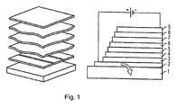
- FIG. 1 shows the schematic layer structure of an organic self-emitting component. From bottom to top the following layer structure is realized:
- the substrate 1 which may be transparent, for example, and may be made of glass.
- the lower electrode layer 2 which may be, for example, a transparent conductive oxide such as zinc oxide, tin oxide, cadmium oxide, titanium oxide, indium oxide or indium tin oxide (ITO) .
- the hole injection layer 3 On which in turn the hole transport layer 4 is arranged is and over which the organic active layer, the emission layer 5 is located.
- the hole blocking layer 6 On the emission layer 5 is the hole blocking layer 6, on which the electron transport layer 7 and finally the electron injection layer 8 with adjoining upper electrode 9, for example a metal electrode or another transparent electrode, e.g. from one of the aforementioned transparent conductive oxides.
- metal complexes are provided in a matrix which have an ionization potential less than or equal to 5 eV.
- the metal complexes according to the invention are provided which have at least one ligand which coordinates via a guanidine anion group on the central atom.
- an ITO layer is first deposited as an anode on a glass plate.
- this substrate is introduced into a recipient; this contains one or more sources in which organic material (for the production of the individual functional layers of the radiation-emitting device such as emitter materials or p- or n-type dopants) can be evaporated. Further, one or more sources are provided for the delivery of one or more different matrix materials.
- To form a hole injection layer is deposited from a source of matrix material and a source of p-type dopant together on the glass plate with the anode. Accordingly, the common deposition of dopant and matrix material for the hole transport layer takes place.
- the common deposition of a matrix material and the metal complex according to the invention and optionally a further phosphorescent compound takes place, the emitter layer being obtained.
- the deposition of further contained layers such as blocking layer, electron transport layer and electron injection layer is analogous.
- a 150 nm thick aluminum layer is formed as a reflective electrode.
- Guanidine derivatives may, for example, according to the manufacturing method according to Dalton Trans., 2006, 4623-4631 .
- Inorganic Chemistry, 2006, 45, 5493-5500 such as Inorg. Chem 1997, 36, 867 and according to the WO 2005/086251 A2 , of the US 4,797,487 and the EP 0 198 680 A1 be synthesized.
- Triamines required for these syntheses are, for example, according to FI 82445 available. This production method is hereby incorporated by reference.
- guanidine derivative 100 mmol of the thiourea derivative are added to a solution of 100 mmol of primary amine in 150 ml of p-xylene. The resulting mixture is then heated under reflux until hydrogen sulfide is no longer formed (about 10 days). The resulting guanidine derivative can be purified by crystallization by cooling the xylene solution and usually also by sublimation:
- n * 1 mmol of sodium methylate (or alternatively butyl lithium) and n * 1 mmol of guanidine derivative are suspended in 40 ml of dichloromethane (where n corresponds to the number of guanidinate ligands to be coordinated) and also cooled to -70 ° C. This suspension is slowly added dropwise to the suspension of the metal salt.
- the reaction mixture is stirred for 48 h at room temperature. It is then filtered through a frit and washed with dichloromethane. The filtrate is concentrated and dried in vacuo.
- the resulting guanidinate complex can be purified by washing with pentane.
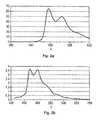
- FIG. 2a the photoluminescence spectrum of compound 8 is shown, with an emission maximum at 498 nm and 531 nm.
- FIG. 2b the photoluminescence spectrum of compound 9 is shown with an emission maximum at 473 nm and 501 nm.
Abstract
Description
Die vorliegende Erfindung betrifft ein organisches strahlungsemittierendes Bauteil wie z.B. eine Organische Leuchtdiode (OLED), das zumindest zwei Elektrodenschichten und dazwischen zumindest eine organische strahlungsemittierende Schicht mit einem Triplettemitter umfasst sowie eine hierfür geeignete phosphoreszente Metallkomplexverbindung.The present invention relates to an organic radiation emitting device, such as e.g. an organic light-emitting diode (OLED) which comprises at least two electrode layers and between them at least one organic radiation-emitting layer with a triplet emitter and a phosphorescent metal complex compound suitable for this purpose.
Diese Patentanmeldung beansprucht die Priorität der deutschen Patentanmeldungen
Der Stand der Technik stellt eine Vielzahl von OLEDs bereit, die rot und/oder grün leuchten. OLEDs, die tiefblau, hellblau und/oder blaugrün strahlenden und annehmbare, weil wirtschaftlich interessantere, Lebensdauern haben sind seltener.The prior art provides a variety of OLEDs that glow red and / or green. OLEDs that have deep blue, light blue, and / or teal radiant and acceptable, because more economically interesting, lifetimes are rare.
Cotton et al. haben gezeigt, dass der hpp-Ligand (Anion des 1,3,4,6,7,8-hexahydro-2H-pyrimido[1,2-a]pyrimidine = Hhpp) die außerordentliche Fähigkeit besitzt, Komplexe in hohen Oxidationsstufen durch seine enorme Basisizät zu stabilisieren (
Die Druckschrift
Aufgabe der vorliegenden Erfindung ist es, eine verbesserte OLED zur Verfügung zu stellen. Diese Aufgabe wird durch ein strahlungsemittierendes organisches Bauteil gemäß Anspruch 1 und durch eine phosphoreszente Metallkomplexverbindung gemäß Anspruch 10 gelöst.The object of the present invention is to provide an improved OLED. This object is achieved by a radiation-emitting organic component according to
Es wird ein strahlungsemittierendes organisches Bauteil angegeben, aufweisend ein Substrat, zumindest eine untere Elektrodenschicht, zumindest eine organische strahlungsemittierende Schicht und darüber zumindest eine obere Elektrodenschicht, wobei in der emittierenden Schicht in einer Matrix zumindest ein strahlungsemittierender Metallkomplex enthalten ist, der zumindest einen Liganden, der über eine Guanidin-Anion-Gruppe am Zentralatom koordiniert ist, aufweist. Nachfolgend wird ein derartiger Ligand, der ein Guanidin-Anion ist oder eine anionische Guanidingruppe enthält auch Guanidinat-Ligand genannt.The invention relates to a radiation-emitting organic component comprising a substrate, at least one lower electrode layer, at least one organic radiation-emitting layer and at least one upper electrode layer, wherein in the emitting layer in a matrix at least one radiation-emitting metal complex containing at least one ligand, the coordinated via a guanidine anion group on the central atom has. Hereinafter, such a ligand which is a guanidine anion or contains an anionic guanidine group is also called a guanidinate ligand.
Vorteilhafterweise enthält der in der Matrix in der Emissionsschicht eingebettete Metallkomplex zumindest einen anionischen Liganden, der die Struktureinheit eines Anions, abgeleitet vom Guandin, also der Guanidin-Anion-Gruppe:

Weitere Metallkomplexe mit niedrigen Ionisierungsenthalpien sind auch aus dem oben zitierten Science-Artikel von Cotton et al. bekannt. Diese Metallkomplexe wurden bislang zur n-Dotierung von organischen halbleitenden Materialien eingesetzt. In der folgenden Tabelle, die aus dem genannten Artikel von Cotton et al. entnommen ist, sind ausgewählte Beispiele derartiger Metallkomplexe, an denen der so genannte "hpp-" Ligand, ein "paddlewheel"-Ligand gebunden ist, dargestellt.
Überraschend hat sich gezeigt, dass Metallkomplexe mit dem dort offenbarten "hpp"-Ligand und auch generell Metallkomplexe mit Guanidinat-Liganden in Emittersystemen oder Emitterschichten für organische Leuchtdioden zu einer effizienten kurzwelligen Emission führen und dabei auch eine ausreichende Stabilität zeigen. Die Emitter eignen sich zum Beispiel zur Emission von roter Strahlung, oranger Strahlung, gelber Strahlung, grüner Strahlung, blauer Strahlung und violetter Strahlung. Zu nennen sind insbesondere auch Emitter, die tiefblau (kleiner etwa 450 nm), hellblau (etwa 450 nm bis 500 nm) und/oder blaugrün (größer etwa 500 nm) emittieren. In den Metallkomplexen können dabei neben den genannten Guanidinat-Liganden auch ein oder mehrere (gleiche oder verschiedene) weitere Liganden (im folgenden Koliganden genannt) enthalten sein.Surprisingly, it has been shown that metal complexes with the "hpp" ligand disclosed therein and also generally metal complexes with guanidinate ligands in emitter systems or emitter layers for organic light-emitting diodes lead to efficient short-wave emission and also show sufficient stability. The emitters are suitable, for example, for the emission of red radiation, orange radiation, yellow radiation, green radiation, blue radiation and violet radiation. Particularly noteworthy are also emitters which emit deep blue (smaller about 450 nm), light blue (about 450 nm to 500 nm) and / or blue-green (greater about 500 nm). In addition to the abovementioned guanidinate ligands, one or more (identical or different) further ligands (called coligands in the following) may be contained in the metal complexes.
Vorteilhafterweise umfasst der Metallkomplex ein Übergangsmetallatom oder ein Lanthanoid als Zentralatom, insbesondere ein Übergangsmetall der 7., 8., 9., 10., oder 11. Gruppe des Periodensystems, bevorzugt Ir, Pt, Au, Re, Rh, Ru, Os, Pd, Ag, Zn; besonders bevorzugt ist Iridium, Platin und Gold. Dabei kann auch mehr als ein substituierter oder unsubstituierter Guanidinat-Ligand gebunden sein.Advantageously, the metal complex comprises a transition metal atom or a lanthanide as the central atom, in particular a transition metal of the 7th, 8th, 9th, 10th or 11th group of the Periodic Table, preferably Ir, Pt, Au, Re, Rh, Ru, Os, Pd, Ag, Zn; particularly preferred is iridium, platinum and gold. In this case, more than one substituted or unsubstituted guanidinate ligand can be bound.
Nachfogend werden die erfindungsgemäß möglichen Bindungsmöglichkeiten des Guanidinat-Liganden an den Metallzentren beispielhaft mit einem hpp-Liganden gezeigt. Der Ligand kann dabei nur an ein Metallzentrum koordiniert sein oder verbrückend wirken. Im Sinne der Erfindung sind auch gemischte Varianten, wo ein hpp-Ligand zweizähnig an ein erstes Metallatom gebunden ist, während ein weiterer an dem ersten Metallatom und einem zweiten Metallatom verbrückend wirkt.


Die Koordinationssphäre des Metallatoms wird gegebenenfalls durch weitere beliebige Koliganden, insbesondere auch Liganden, abgeleitet vom Guandingerüst vervollständigt.The coordination sphere of the metal atom is optionally completed by any further coligands, in particular also ligands derived from the guanine skeleton.
Gemäß vorliegender Erfindung haben sich nicht nur Komplexe mit dem hpp-Ligand selbst in Emissionsschichten strahlungsemittierender Bauteile als vorteilhaft erwiesen, sondern insbesondere auch Liganden mit einem in vielfältiger Weise modifizierten Guandin-Grundgerüst.According to the present invention, not only complexes with the hpp ligand have proved advantageous even in emission layers of radiation-emitting components, but in particular also ligands with a modified in many ways guanine skeleton.
Bislang wurden die Guanidinat-Liganden nicht für Emittersysteme benutzt, weil ein wissenschaftliches Vorurteil bestand, die nicht voll durchkonjugierten Liganden, wie die mit Guanidin-Gruppe, würden sich für Emittersysteme nicht eignen. Unter einem voll durchkonjugierten Liganden wird hierbei ein Ligand verstanden, der mindestens einen Aromaten und/oder mehrere konjugierte Doppelbindungen enthält.So far, the guanidinate ligands have not been used for emitter systems because of a scientific bias that the non-fully conjugated ligands, such as those with a guanidine group, would not be suitable for emitter systems. Under a fully durchkonjugierten ligand is here understood a ligand containing at least one aromatic and / or more conjugated double bonds.
Erfindungsgemäß wurde hingegen festgestellt, dass Guanidinat-Liganden zur Stabilisierung in metallorganischen phosphoreszenten Emittern herangezogen werden können, obwohl in diesen kein durchkonjugiertes System vorliegt. Die Emissionswellenlänge der erfindungsgemäßen Guanidinat-Komplexe kann daher auch vom Koliganden bestimmt sein. Weiterhin wurde festgestellt, dass der Guanidinat-Ligand den emittierenden Komplex gegenüber Elektronen stabilisiert. Die Guanidinat-Liganden können dabei weitere Substituenten enthalten, die die Koordination an weitere Metallatome fortsetzen. Dann entstehen mehrkernige Komplexe.According to the invention, however, it was found that guanidinate ligands can be used for stabilization in organometallic phosphorescent emitters, although there is no durchkonjugiertes system in these. The emission wavelength of the guanidinate complexes according to the invention can therefore also be determined by the coligand. Furthermore, it was found that the guanidinate ligand stabilizes the emitting complex towards electrons. The guanidinate ligands may contain further substituents, which continue the coordination to other metal atoms. Then arise polynuclear complexes.
Somit enthält der in der Matrix der Emissionsschicht eingebettete Metallkomplex zumindest einen anionischen Liganden mit der allgemeinen Strukturformel:

Durch Variation der der Reste R1, R2, R3 und R4 lassen sich verschiedenartige Liganden erzeugen, die geeignet für die Emittersysteme im erfindungsgemäßen Bauteil sind. R1, R2, R3 und R4 können dabei unabhängig voneinander H, unverzweigte (z.B. Methyl-, Ethyl-), verzweigte, kondensierte (wie z.B. Decahydronaphthyl-) und ringförmige (wie z. B. Cyclohexyl-) Alkylreste, Aromaten, kondensierte Aromaten, Heterocyclen und kondensierte Heterocyclen sowie gegebenenfalls vollständig oder teilweise substituierte Alkylreste, Aromaten, kondensierte Aromaten, Heterocyclen und kondensierte Heterocyclen sein.
Weiterhin können die Gruppen R1 und R4 und/oder die Gruppen R2 und R3 (und gegebenenfalls auch die Gruppen R3 und R4) miteinander verbunden sein, und insbesondere eine Alkylen-Brücke darstellen, so das ein Ring ausgebildet wird, der insbesondere 5- oder 6-gliedrig sein kann. Die Alkylreste und Alkylenreste können Ethergruppen (Ethoxy-, Methoxy-, Propoxy-, usw.), Ester-, Amid-, Carbonatgruppen etc. enthalten. R1, R2, R3 und R4 sind - wie erwähnt - nicht auf gesättigte Systeme beschränkt, sondern können auch folgende Reste beinhalten bzw. hierin bestehen: substituierte bzw. unsubstituierte Aromaten und Heterocyclen. Als Aromaten sind hierbei insbesondere zu nennen: Phenyl, Diphenyl, Naphthyl, Phenanthryl etc. bzw. Benzyl etc. Eine Zusammenstellung in Frage kommender Heterocyclen ist nachfolgend dargestellt:


Furthermore, the groups R 1 and R 4 and / or the groups R 2 and R 3 (and optionally also the groups R 3 and R 4 ) may be connected to one another, and in particular represent an alkylene bridge, so that a ring is formed, which may in particular be 5- or 6-membered. The alkyl radicals and alkylene radicals may contain ether groups (ethoxy, methoxy, propoxy, etc.), ester, amide, carbonate groups, etc. R 1 , R 2 , R 3 and R 4 are - as mentioned - not limited to saturated systems, but may also include or consist of the following: substituted or unsubstituted aromatics and heterocycles. Particular examples of aromatics are phenyl, diphenyl, naphthyl, phenanthryl etc. or benzyl, etc. A list of suitable heterocycles is shown below:
Dies ist nur eine Auswahl von substituierten bzw, unsubstituierten Heterozyklen, die als Reste R1, R2, R3 und R4 oder als Bestandteil dieser Reste in Frage kommen. Der Einfachheit halber ist nur die Grundeinheit dargestellt. Die Bindung an den Liganden kann an jeder bindungsfähigen Stelle des Grundkörpers oder einen Linker erfolgen. Zudem können diese Reste selbst noch beispielweise durch elektronenziehende oder e-lektronschiebende Gruppen substituiert sein.This is only a selection of substituted or unsubstituted heterocycles which are suitable as radicals R 1 , R 2 , R 3 and R 4 or as a constituent of these radicals. For simplicity, only the basic unit is shown. The binding to the ligand can be done at any bondable site of the body or a linker. In addition, these radicals may themselves be substituted, for example, by electron-withdrawing or electron-donating groups.
Als Koliganden kommen alle Liganden und Ligandensysteme in Frage, die bislang in Komplexen, die als Emitter in organischen selbstemittierenden Bauteile wie beispielsweise in OLEDs (organischen Leuchtdioden) verwendet wurden oder als dazu geeignet beschrieben wurden, in Betracht. Grundsätzlich eignen sich im Wesentlichen einzähnige, zweizähnige oder mehrzähnige über ein C-, N-, P-, As-, Sb-, O-, S- und/oder Se-Atom an das Zentralatom koordinierte Koliganden. Einige bekannte Beispiele für Koliganden finden sich beispielsweise in
Als Koliganden sind auch Liganden geeignet, die über eine Fluorierung der Phenylpyridin-Liganden in Bis(2,4-difluorophenyl-2-pyridyl)-Iridium(III)-picolinat (FIrPic) oder Bis(2,4-difluorophenylpyridinato)-tetrakis(1-pyrazolyl)borate-Iridium(III) (FIr6) erhalten werden. Die Fluorierung verschiebt die Emission zu kürzeren Wellenlängen. weiterhin geeignet sind Carbenliganden (
Der Inhalt der vorstehend in Bezug auf die Koliganden genannten Druckschriften, insbesondere was Struktur und Synthese der Koliganden betrifft, soll hiermit per Referenz Bestandteil der Offenbarung der vorliegenden Beschreibung sein. Alle Verbindungen in den genannten Patenten sind in diese Erfindungsmeldung einbezogen, sofern sie die beschriebenen Bedingungen durch die beanspruchte Modifikation erfüllen.The contents of the references mentioned above in relation to the coligands, in particular as regards the structure and synthesis of the coligands, are hereby incorporated by reference into the disclosure of the present description. All compounds in said patents are incorporated in this invention unless they meet the conditions described by the claimed modification.
Im Unterschied zu Metallkomplexen, die ausschließlich Koliganden enthalten, weisen die erfindungsgemäßen Komplexe mit Liganden, die über eine darin enthaltene Guanidin-Anion-Gruppe an das Zentralatom koordiniert sind, eine verbesserte Stabilität und eine leichtere Zugänglichkeit auf.In contrast to metal complexes containing exclusively coligands, the complexes according to the invention with ligands coordinated to the central atom via a guanidine anion group contained therein have improved stability and easier accessibility.
Bevorzugt wird durch die Liganden, die über eine darin enthaltene Guanidin-Anion-Gruppe an das Zentralatom koordiniert sind, in homo- bzw. heteroleptischen organometallischen Komplexen zumindest ein Zentralatom insbesondere in der Oxidationsstufe Ir(III), Pt(II) und/oder Au(I) stabilisiert, wobei das Emissionspektrum des Komplexes - sofern die vorstehend angegebenen Koliganden enthalten sind - zur kürzeren Emissionswellenlängen verschoben wird und/oder die Stabilität gegenüber Elektronen im fertigen OLED-Bauteil erhöht wird.Preferably, the ligands which are coordinated to the central atom via a guanidine anion group contained therein, in homo- or heteroleptic organometallic complexes at least one central atom, in particular in the oxidation state Ir (III), Pt (II) and / or Au (I) stabilized, wherein the emission spectrum of the complex - if the above-mentioned coligands are included - shifted to shorter emission wavelengths and / or increases the stability to electrons in the finished OLED device becomes.
Im Folgenden sollen zur Erläuterung einige beispielhafte, geeignete Guanidinat-Liganden aufgezeigt werden:The following are illustrative examples of some suitable guanidinate ligands:
Besonders bevorzugt ist das hpp-Anion selbst (nachfolgende mit 5a bezeichnet). Die Länge der beiden Brücken, die die Stickstoffatome miteinander verbinden können unabhängig voneinander variiert werden (nachfolgend mit 5b bezeichnet). Dabei sind n bzw. m ganze Zahlen, die unabhängig voneinander zwischen 1 und 10 gewählt werden können, wobei n und/oder m mit 2, 3 oder 4 bevorzugt sind. Die nachfolgend als 5c bezeichnete Struktur zeigt beispielhaft das verbrückte Guanidingrundgerüst mit n und m = 3. Die Substituenten R1 - R12 können gleich oder verschieden sein und haben hierbei die selbe Bedeutung wie die Substituenten R1 - R4, die vorstehend für die allgemeine Struktur des Guanidinat-Liganden definiert wurden. Im Unterschied dazu können in Struktur 5c auch jeweils zwei Substituenten zueinander benachbarter KohlenstoffAtome miteinander verbunden sein, und insbesondere Alkylen-Brücken darstellen, so dass ein, zwei oder mehrere Ringe ausgebildet werden, die unabhängig voneinander insbesondere 5-oder 6-gliedrig sein können.

Weiterhin geeignet sind Verbindungen der nachfolgenden Strukturen 6a und 6b; sie zeigen ein Derivat mit kondensierten aromatischen Ringsystemen. Besonders bevorzugt ist hier n = 0, 1, 2 und m = 0, 1, 2. Die Substituenten R1 bis R4 in Struktur 6b können dabei können gleich oder verschieden sein und haben die selbe Bedeutung wie die Substituenten R1 - R4, die vorstehend für die allgemeine Struktur des Guanidinat-Liganden definiert wurden. Anders also dort definiert, können in Struktur 6b die Substituenten R1 oder R2 mit den Substituenten R3 oder R4 verbunden sein, und insbesondere eine Alkylen-Brücke darstellen, so dass ein Ring ausgebildet wird, der insbesondere 5- oder 6-gliedrig sein kann. Die Substituenten R5 und R6 in Struktur 6a und 6b stehen für ein komplettes Substitutionsmuster, das auch aus mehreren einzelnen Substituenten, die jeweils die vorstehende Bedeutung der Reste R1 - R4 haben können, aufgebaut sein kann.

Weiterhin geeignet sind Verbindungen der nachfolgenden Strukturen 7a-c. Sie zeigen verschiedene Liganden mit zentralem Guanidinkern mit aromatischen Substituenten. Diese können dabei einzeln (7a), verbrückend - wobei sowohl Brücken zwischen verschiedenen aromatischen Substituenten (7b) als auch Brücken zwischen zwei an einen aromatischen Substituenten gebundenen Subsituenten Rx vorliegen können - oder kondensiert (7c) angeordnet sein. Rx (x = 1 - 4) können gleich oder verschieden sein und stellen dabei jeweils einen oder mehrere an einen Ring gebundene Substituenten, die wie vorstehend für die allgemeine Struktur des Guanidinat-Liganden definiert sind, dar.


Ferner geeignet sind Verbindungen der nachfolgenden Strukturen 8a-8d und 9a-9h.Die Sturkuren 8a-8d stellen Guanidinderivate mit gesättigten Ringsystemen bzw. Substituenten dar. Rx (x = 1 - 4) können darin gleich oder verschieden sein und stellen dabei jeweils einen oder mehrere an einen Ring gebundene Substituenten, der wie vorstehend für die allgemeine Struktur des Guanidinat-Liganden definiert ist, dar.


Die Sturkuren 9a-9h stellen gemischte bzw. höher kondensierte Varianten der Strukturen 7 a-d und 8 a-d dar.


Im Sinne der Erfindung sind auch Guandinderivate, die weitere heterozyklische Substituenten (aromatisch oder aliphatisch) enthalten, geeignet. Nachfolgend sind einige Strukturformeln abgebildet, die Guandinderivate mit ankondensierten sechsgliederigen Ringen zeigen. Im Falle.aromatischer Ringe können X1-X10 unabhängig voneinander C-H bzw. C-R oder N sein. Im Falle aliphatischer Ringe können X1-X10 unabhängig voneinander CH2, -C-HR bzw. C-R1R2 oder N bzw. NH oder NR sein. Die Reste R bzw. R1 bzw. R2 können hierbei jeweils gleich oder verschieden sein und stellen Substituenten, die wie vorstehend für die allgemeine Struktur des Guanidinat-Liganden definiert sind, dar.


In analoger Weise sind auch Vertreter der vorstehenden Guandinderivate mit ankondensierten Chinolin- und Isochinolin-Gruppen geeignet. Weiterhin geeignet sind Guandinderivate, bei denen die vorstehend gezeigten aromatischen Ringe auch hydriert sind und/oder mit einem bzw. mehreren Substituenten R substituiert sind (Die Reste R können hierbei gleich oder verschieden sein und stellen Substituenten, die wie vorstehend für die allgemeine Struktur des Guanidinat-Liganden definiert sind, dar).In an analogous manner, representatives of the above guanine derivatives with fused quinoline and isoquinoline groups are also suitable. Also suitable are guanine derivatives in which the aromatic rings shown above are also hydrogenated and / or substituted by one or more substituents R (The radicals R may be the same or different and represent substituents as above for the general structure of the guanidinate Ligands are defined).
Schließlich sind auch Guanidinderivate der nachfolgenden Strukturen (mit Imidazol bzw. Benzimidazolsubstituenten) geeignet. Die Substituenten R1-R8 können hierbei gleich oder verschieden sein und stellen Substituenten, die wie vorstehend für die Guandin-Anion-Gruppe definiert sind, dar. Ist jedoch wenigstens R1 oder R2 = H besteht die Möglichkeit durch eine weitere Deprotonierung zweifach negativ geladene Ligandensysteme zu erhalten. In analoger weise sich auch Guanidinderivate mit Pyrazol-Gruppen geeignet.


Des Weiteren sind im Sinne der Erfindung Liganden mit Guanidingrundgerüst geeignet, die zusätzlich P, S, O, As, Sb, F, oder auch metallorganische Substituenten, wie bespielweise Ferrocenyl, Phthalocyaninyl (wobei das Zentralatom Zn, Fe, Ni etc. sein kann) enthalten.Furthermore, ligands with guanidine skeleton are suitable for the purposes of the invention which additionally may be P, S, O, As, Sb, F or organometallic substituents, such as ferrocenyl, phthalocyaninyl (where the central atom may be Zn, Fe, Ni, etc.) contain.
Mit der Erfindung gelingt erstmals die Identifikation eines Strukturelements, das zur Erhöhung der Stabilität in metallorganischen phosphoreszenten Emittern, insbesondere in Triplettemittern herangezogen werden kann. Die erfindungsgemäßen Liganden beinhalten das Anion eines Guanidin-Derivates, das in verschiedenartiger Weise an Metallatome koordiniert werden kann. Die anionischen Liganden werden dabei durch Deprotonierung des entsprechenden neutralen Liganden mit Guandineinheit erhalten. Die Ligandsysteme können dabei weitere Substituenten enthalten, die die Koordination an weitere Metallatome fortsetzen.The invention makes it possible for the first time to identify a structural element which can be used to increase the stability in organometallic phosphorescent emitters, in particular in triplet emitters. The ligands of the invention include the anion of a guanidine derivative which can be coordinated in various ways to metal atoms. The anionic ligands are obtained by deprotonation of the corresponding neutral ligand with guandine unit. The ligand systems may contain further substituents, which continue the coordination to other metal atoms.
Die Erfindung wird nachfolgend noch anhand von Figuren und Ausführungsbeispielen näher erläutert:
-
Figur 1 -
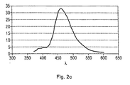
Figur 2a bis c zeigt Photolumineszenzspektren für verschiedene Metallkomplexverbindungen.
-
FIG. 1 shows the schematic side view of a radiation-emitting device. -
FIGS. 2a to c shows photoluminescence spectra for various metal complex compounds.
Die
Ganz unten befindet sich das Substrat 1, das beispielsweise transparent sein kann und aus Glas sein kann. Darauf befindet sich die untere Elektrodenschicht 2, die beispielsweise ein transparentes leitendes Oxid wie beispielsweise Zinkoxid, zinnoxid, Cadmiumoxid, Titanoxid, Indiumoxid oder Indiumzinnoxid (ITO) sein kann.. Über dieser Elektrodenschicht 2 liegt die Lochinjektionsschicht 3 , über der wiederum die Lochtransportschicht 4 angeordnet ist und über der die organische aktive Schicht, die Emissionsschicht 5 liegt. Auf der Emissionsschicht 5 liegt die Lochblockierende Schicht 6, auf der die Elektronentransportschicht 7 und schließlich die Elektroneninjektionsschicht 8 mit angrenzender oberer Elektrode 9, beispielsweise einer Metallelektrode oder einer weiteren transparenten Elektrode, z.B. aus einem der vorstehend genannten transparenten leitenden Oxide.At the bottom is the
Bei Anlegen einer Spannung zwischen oberer und unterer Elektrode fließt Strom durch das Bauteil und in der organischen aktiven Schicht 5 werden Photonen freigesetzt, die in Form von Licht über die untere Elektrode 2 und das Substrat 1 das Bauteil verlassen.When a voltage is applied between the upper and lower electrodes, current flows through the component and in the organic
In der Emissionsschicht 5 sind erfindungsgemäß in einer Matrix Metallkomplexe vorgesehen, die ein Ionisierungspotential kleiner/gleich 5 eV haben. Insbesondere sind die erfindungsgemäßen Metallkomplexe vorgesehen, die zumindest einen Liganden, der über eine Guanidin-Anion-Gruppe am Zentralatom koordiniert, aufweisen.In the
Die Herstellung eines derartigen strahlungsemittierenden Bauteils kann z.B. folgendermaßen erfolgen:The production of such a radiation-emitting component may be e.g. as follows:
Mittels HF-Sputtern wird zunächst eine ITO-Schicht als Anode auf einer Glasplatte abgeschieden. Zur Abscheidung der weiteren funktionellen Schichten wird dieses Substrat in einen Rezepienten eingebracht; dieser enthält eine oder mehrere Quellen, in denen organisches Material (zur Herstellung der einzelnen funktionellen Schichten der strahlungsemittierenden Vorrichtung wie Emittermaterialien oder p- oder n-Dotanten) verdampft werden kann. Ferner werden ein oder mehrere Quellen für die Zuführung von einem oder mehreren verschiedenen Matrixmaterialien vorgesehen. Zur Ausbildung einer Lochinjektionsschicht wird aus einer Quelle mit Matrixmaterial und einer Quelle mit p-Dotant gemeinsam auf der Glasplatte mit der Anode abgeschieden. Entsprechend erfolgt die gemeinsame Abscheidung von Dotant und Matrixmaterial für die Lochtransportschicht. Anschließend erfolgt die gemeinsame Abscheidung eines Matrixmaterials und des erfindungsgemäßen Metallkomplexes und gegebenenfalls einer weiteren phosphoreszierenden Verbindung, wobei die Emitterschicht erhalten wird. Die Abscheidung weiterer enthaltener Schichten wie Blockierschicht, Elektronentransportschicht und Elektroneninjektionsschicht erfolgt analog. Abschließend wird eine 150 nm dicke Aluminiumschicht als reflektive Elektrode gebildet.Using RF sputtering, an ITO layer is first deposited as an anode on a glass plate. For depositing the further functional layers, this substrate is introduced into a recipient; this contains one or more sources in which organic material (for the production of the individual functional layers of the radiation-emitting device such as emitter materials or p- or n-type dopants) can be evaporated. Further, one or more sources are provided for the delivery of one or more different matrix materials. To form a hole injection layer is deposited from a source of matrix material and a source of p-type dopant together on the glass plate with the anode. Accordingly, the common deposition of dopant and matrix material for the hole transport layer takes place. Subsequently, the common deposition of a matrix material and the metal complex according to the invention and optionally a further phosphorescent compound takes place, the emitter layer being obtained. The deposition of further contained layers such as blocking layer, electron transport layer and electron injection layer is analogous. Finally, a 150 nm thick aluminum layer is formed as a reflective electrode.
Im Folgenden werden Ausführungsbeispiele zur Herstellung von Übergangskomplexverbindungen angegeben.In the following, exemplary embodiments are given for the preparation of transition complex compounds.
Guanidinderivate können beispielsweise nach den Herstellungsverfahren gemäß
100 mmol Schwefelkohlenstoff werden zu einer Lösung von 100 mmol Triamin in 150 ml p-Xylol zugefügt. Das erhaltene Gemisch wird anschließend so lange unter Rückfluss erhitzt, bis kein Schwefelwasserstoff mehr gebildet wird (ca. 10 Tage). Das bicyclische Guanidin kann mittels Kristallisation durch Abkühlen der Xylol-Lösung und üblicherweise auch durch Sublimation gereinigt werden.
Die Synthese wird nachfolgend anhand eines substituierten oder unsubstituerten N-3-Aminopropyl-1,3-propandiamins gezeigt:

The synthesis is shown below with reference to a substituted or unsubstituted N-3-aminopropyl-1,3-propanediamine:
100 mmol des Thioharnstoff-Derivats werden zu einer Lösung von 100 mmol primärem Amin in 150 ml p-Xylol zugefügt. Das erhaltene Gemisch wird anschließend so lange unter Rückfluss erhitzt, bis kein Schwefelwasserstoff mehr gebildet wird (ca. 10 Tage). Das erhaltene Guanidin-Derivat kann mittels Kristallisation durch Abkühlen der Xylol-Lösung und üblicherweise auch durch Sublimation gereinigt werden:

1 mmol eines Metallsalzes der Formel L1 kL2 mMXn oder der Formel [L1 kL2 m-1MXn]2 werden in 20 ml Dichlormethan oder in 20 ml Tetrahydrofuran suspendiert und auf -70°C abgekühlt. Ferner wird jeweils n*1 mmol Natriummethylat (oder alternativ Butyllithium) und n*1 mmol Guanidinderivat in 40 ml Dichlormethan suspendiert (hierbei entspricht n der Anzahl zu koordinierender Guanidinat-Liganden) und ebenfalls auf -70°C gekühlt. Diese Suspension wird langsam zur Suspension des Metallsalzes zugetropft. Die Reaktionsmischung wird 48h bei Raumtemperatur gerührt. Anschließend wird über eine Fritte filtriert und mit Dichlormethan nachgewaschen. Das Filtrat wird eingeengt und im Vakuum getrocknet. Gegebenenfalls kann der erhaltene Guanidinat-Komplex durch Waschen mit Pentan gereinigt werden.1 mmol of a metal salt of the formula L 1 k L 2 m MX n or the formula [L 1 k L 2 m-1 MX n ] 2 are suspended in 20 ml of dichloromethane or in 20 ml of tetrahydrofuran and cooled to -70 ° C. Furthermore, in each case n * 1 mmol of sodium methylate (or alternatively butyl lithium) and n * 1 mmol of guanidine derivative are suspended in 40 ml of dichloromethane (where n corresponds to the number of guanidinate ligands to be coordinated) and also cooled to -70 ° C. This suspension is slowly added dropwise to the suspension of the metal salt. The reaction mixture is stirred for 48 h at room temperature. It is then filtered through a frit and washed with dichloromethane. The filtrate is concentrated and dried in vacuo. Optionally, the resulting guanidinate complex can be purified by washing with pentane.
Bei der angegebenen Formel des Metallkomplexes entspricht L1 einem beliebigen Liganden; k entspricht der Anzahl pro Metall koordinierter L1-Liganden und kann auch 0 sein; L2 entspricht einem beliebigen Neutralliganden, der bei der Umsetzung mit dem Guanidinat-Liganden abgespalten wird (z.B. ein C2H4-Ligand); m entspricht der Anzahl pro Metall koordinierter L2-Liganden und ist > 0, für einzähnige Neutralliganden (wie z.B. C2H4) gilt m-1=n; X ist ein Halogen-Ligand oder ein anderer einfach negativ geladener Ligand (z.B. ein Carboxylat-Ligand wie Acetat); n entspricht der Anzahl zu koordinierender Guanidinat-Liganden bzw. der Anzahl der Liganden X;In the given formula of the metal complex, L 1 corresponds to any ligand; k is the number of L 1 ligands coordinated per metal and may also be 0; L 2 corresponds to any neutral ligand that is cleaved upon reaction with the guanidinate ligand (eg, a C 2 H 4 ligand); m corresponds to the number of L 2 ligands coordinated per metal and is>0; for monodentate neutral ligands (such as C 2 H 4 ) m-1 = n; X is a halogen ligand or other simply negatively charged ligand (eg, a carboxylate ligand such as acetate); n corresponds to the number of guanidinate ligands to be coordinated or the number of ligands X;

12 mmol (4,98 g) Kaliumtetrachloroplatinat werden in 24 ml heißem entgastem Wasser gelöst und unter starkem Rühren wieder abgekühlt. Dabei fällt das Kaliumtetrachloroplatinat als feine Suspension aus. Zu dieser Suspension wird eine Lösung von 12 mmol (1,86 g) Phenylpyridin in 72 ml Ethoxyethanol zugetropft. Die Suspension wird auf 70°C erhitzt, wobei sich zunehmend ein dunkelgrüner Niederschlag bildet. Die Suspension wird zum Ausfällen des Rohprodukts mit 30 ml Wasser unterschichtet und nach ca. 2h umgerührt. Das Rohprodukt wird abgesaugt und mehrmals mit einem Wasser/Alkohol-Gemisch (10:1) gewaschen. An dieser Stelle wird das Produkt luftstabil. Anschließend wird es im Vakuum ca. 20h getrocknet. Verschiedene Chargen zeigen im Feststoff eine gelbe bis grüne Färbung je nach Anteil an Verunreinigungen. Das Rohprodukt kann jedoch ohne weitere Reinigung für die folgenden Versuche verwendet werden.
Ausbeute: : 3,56 g (77,2%)12 mmol (4.98 g) of potassium tetrachloroplatinate are dissolved in 24 ml of hot degassed water and cooled again with vigorous stirring. The potassium tetrachloroplatinate precipitates as a fine suspension. A solution of 12 mmol (1.86 g) of phenylpyridine in 72 ml of ethoxyethanol is added dropwise to this suspension. The suspension is heated to 70 ° C, which increasingly forms a dark green precipitate. The suspension is underlaid to precipitate the crude product with 30 ml of water and stirred after about 2 hours. The crude product is filtered off with suction and washed several times with a water / alcohol mixture (10: 1). At this point the product becomes air-stable. It is then dried in vacuo for about 20 hours. Different batches show in the solid a yellow to green color depending on the proportion of impurities. However, the crude product can be used without further purification for the following experiments.
Yield: 3.56 g (77.2%)

7,23 mmol (3 g) Kaliumtetrachloroplatinat werden in 14 ml heißem entgastem Wasser gelöst und unter starkem Rühren auf 30°C abgekühlt. Dabei fällt das Kaliumtetrachloroplatinat als feine Suspension aus. Zu dieser Suspension wird eine Lösung von 7,23 mmol (1,387g) 2,4-Difluor-phenylpyridin in 42 ml Ethoxyethanol langsam zugetropft. Die Suspension wird ca. 20h auf 70°C erhitzt, wobei sich zunehmend ein gelb-grüner Niederschlag bildet. Die Suspension wird nach Abkühlen auf Raumtemperatur zum Ausfällen des Rohprodukts mit 30 ml Wasser unterschichtet und nach ca. 2h umgerührt. Das gelb-grüne Rohprodukt wird abgesaugt und mehrmals mit einem Wasser/AlkoholGemisch (10:1) gewaschen. Im Exsikkator unter Vakuum ca. 20h trocknen.
Ausbeute: 2,36g (78%)7.23 mmol (3 g) of potassium tetrachloroplatinate are dissolved in 14 ml of hot degassed water and cooled to 30 ° C. with vigorous stirring. The potassium tetrachloroplatinate precipitates as a fine suspension. A solution of 7.23 mmol (1.387 g) of 2,4-difluoro-phenylpyridine in 42 ml of ethoxyethanol is slowly added dropwise to this suspension. The suspension is heated to 70 ° C. for approx. 20 h, whereby a yellow-green precipitate increasingly forms. The suspension, after cooling to room temperature to precipitate the crude product underlaid with 30 ml of water and stirred after about 2 hours. The yellow-green crude product is filtered off with suction and washed several times with a water / alcohol mixture (10: 1). Dry in a desiccator under vacuum for approx. 20h.
Yield: 2.36 g (78%)

3 mmol (1,245 g) Kaliumtetrachloroplatinat werden in 6 ml heißem entgastem Wasser gelöst und unter starkem Rühren auf 30°C abgekühlt. Dabei fällt das Kaliumtetrachloroplatinat als feine Suspension aus. Zu dieser Suspension wird eine Lösung von 3 mmol (0,514 g) Dipyridylamin in 45 ml Ethoxyethanol langsam zugetropft. Die Suspension wird ca. 20h auf 70°C erhitzt, wobei sich zunehmend ein cremefarbener Niederschlag bildet. Die Suspension wird nach Abkühlen auf Raumtemperatur zum Ausfällen des Rohprodukts mit 40 ml Wasser unterschichtet und nach ca. 2h umgerührt. Das Rohprodukt wird abgesaugt und mehrmals mit einem Wasser/Alkohol-Gemisch (10:1) gewaschen. Im Exsikkator unter Vakuum ca. 20h trocknen.
Ausbeute: 1 g (83%)3 mmol (1.245 g) of potassium tetrachloroplatinate are dissolved in 6 ml of hot degassed water and cooled to 30 ° C. with vigorous stirring. The potassium tetrachloroplatinate precipitates as a fine suspension. A solution of 3 mmol (0.514 g) of dipyridylamine in 45 ml of ethoxyethanol is slowly added dropwise to this suspension. The suspension is heated to 70 ° C for about 20 hours, whereby an increasingly cream-colored precipitate forms. After cooling to room temperature, the suspension is underlaid with 40 ml of water to precipitate the crude product and stirred after about 2 h. The crude product is filtered off with suction and washed several times with a water / alcohol mixture (10: 1). Dry in a desiccator under vacuum for approx. 20h.
Yield: 1 g (83%)

0,39 mmol (0,3 g) Di(µ-chloro)-bis[(phenyl-pyridino)platin(II)] (Verbindung 1) werden in 25 ml Dichlormethan suspendiert. Gleichzeitig werden 0,78 mmol (108,6 mg) Hhpp und 0,78 mmol (42,13 mg) Natriummethylat in 20 ml Dichlormethan suspendiert. Beide Suspensionen werden unter dem Rühren auf -70°C abgekühlt und dann Hhpp-Suspension wird zu der Di(µ-chloro)-bis[(phenyl-pyridino)platin(II)]-Suspension zugegeben. Die Mischung wird ca. 48h bei Raumtemperatur gerührt. Nach 48h wird das Gemisch über eine P4-Fritte abfiltriert und mit Dichlormethan mehrmals nachgewaschen. Die Lösung wird im Vakuum eingeengt. Anschließend wird die Substanz mit Pentan gewaschen. Die Pentan-Extraktion zeigt aber im Photolumineszenzspektrum das gleiche Ergebnis, wie das gewaschene Produkt.
Ausbeute: praktisch quantitativ0.39 mmol (0.3 g) of di (μ-chloro) -bis [(phenylpyridino) -platinum (II)] (compound 1) are suspended in 25 ml of dichloromethane. At the same time, 0.78 mmol (108.6 mg) of Hhpp and 0.78 mmol (42.13 mg) of sodium methylate are suspended in 20 ml of dichloromethane. Both suspensions are cooled to -70 ° C with stirring and then Hhpp suspension is added to the di (μ-chloro) bis [(phenylpyridino) platinum (II)] suspension. The mixture is stirred for about 48 h at room temperature. After 48 h, the mixture is filtered through a P4 frit and washed several times with dichloromethane. The solution is concentrated in vacuo. Subsequently, the substance is washed with pentane. However, the pentane extraction shows the same result in the photoluminescence spectrum as the washed product.
Yield: practically quantitative
In

1,19 mmol (1 g) Di(µ-chloro)-bis[(2,4-difluor-phenyl-pyridino)platin(II)] (Verbindung 2) werden in 20 ml Dichlormethan suspendiert und auf -70°C abgekühlt. Dazu wird eine Mischung aus 2,377 mmol (128,4 mg) Natriummethylat und 2,377 mmol (330,9 mg) Hhpp, suspendiert in 40 ml Dichlormethan und ebenfalls auf -70°C gekühlt, langsam zugetropft. Die grünliche Reaktionsmischung wird 48h bei Raumtemperatur gerührt, wobei sich die Mischung bräunlich färbt. Anschließend wird über eine Fritte filtriert und mit Dichlormethan.nachgewaschen. Das Filtrat wird eingeengt, man erhält ein bräunlichbeiges Produkt. Eine mit Ether herausgelöste Fraktion ergibt das gleiche PL-Spektrum wie das Rohprodukt.
Ausbeute: praktisch quantitativ1.19 mmol (1 g) of di (μ-chloro) -bis [(2,4-difluorophenyl-pyridino) -platinum (II)] (compound 2) are suspended in 20 ml of dichloromethane and cooled to -70 ° C , For this purpose, a mixture of 2.377 mmol (128.4 mg) of sodium methylate and 2.377 mmol (330.9 mg) of Hhpp, suspended in 40 ml of dichloromethane and also cooled to -70 ° C., is slowly added dropwise. The greenish reaction mixture is stirred for 48 h at room temperature, whereby the mixture turns brownish. It is then filtered through a frit and washed with Dichlormethan.nachgewaschen. The filtrate is concentrated, giving a brownish beige product. A fraction eluted with ether gives the same PL spectrum as the crude product.
Yield: practically quantitative
In

1,25 mmol (1 g) Di(µ-chloro)-bis[(di-pyridylamino)platin(II)] (Verbindung 3) werden in 10 ml Dichlormethan suspendiert und auf -70°C abgekühlt. Dazu wird eine Mischung aus 2,496 mmol (134,8 mg) Natriummethylat und 2,496 mmol (347,4 mg) Hhpp, suspendiert in 35 ml Dichlormethan und ebenfalls auf -70°C gekühlt, langsam zugetropft. Die Reaktionsmischung färbt sich dabei gelb. Man lässt 48h unter Rühren bei Raumtemperatur reagieren. Danach wird die Substanz durch die P4-Fritte abfiltriert und mit Dichlormethan mehrmals nachgewaschen. Das Filtrat wird eingeengt und im Vakuum getrocknet.
Ausbeute 1,04 g (83%)1.25 mmol (1 g) of di (μ-chloro) -bis [(di-pyridylamino) -platinum (II)] (Compound 3) are suspended in 10 ml of dichloromethane and cooled to -70 ° C. For this purpose, a mixture of 2.496 mmol (134.8 mg) of sodium methylate and 2.496 mmol (347.4 mg) of Hhpp, suspended in 35 ml of dichloromethane and likewise cooled to -70 ° C., is slowly added dropwise. The reaction mixture turns yellow. The mixture is allowed to react with stirring at room temperature for 48 h. Thereafter, the substance is filtered off through the P4 frit and washed several times with dichloromethane. The filtrate is concentrated and dried in vacuo.
Yield 1.04 g (83%)
In
Claims (12)
- Radiation-emitting organic component comprising a substrate (1), at least one lower electrode layer (2), at least one organic radiation-emitting layer (5) and an upper electrode layer (9) arranged above it, said radiation-emitting layer (5) having a matrix in which at least one radiation-emitting metal complex is present and has at least one substituted or unsubstituted quanidinate ligand with a guanidine anion group, said guanidine anion group being doubly coordinated to the central atom present in the metal complex or bridging the at least two metal atoms in an at least dinuclear metal complex.
- Component according to Claim 1, wherein the component in each case also has one or more auxiliary layers as well as the radiation-emitting layer (5) between the electrode layers.
- Component according to Claim 1 or 2, wherein the substrate (1) and the lower electrode layer (2) are transparent.
- Component according to any of Claims 1 to 3, wherein the metal complex present in the radiation-emitting layer (5) has at least one central atom selected from the group of the transition metals and the lanthanoids.
- Component according to any of Claims 1 to 4, wherein the metal complex present in the radiation-emitting layer (5) has at least one hpp ligand as the guanidinate ligand.
- Component according to any of the preceding claims, wherein at least two of the nitrogen atoms of the guanidinate ligand are bridged by hydrocarbon bridges which are substituted or unsubstituted and/or aromatic, fused aromatic or nonaromatic and/or heterocyclic.
- Component according to any of the preceding claims, wherein the guanidinate ligand is bicyclic and the bicyclic system contains the nitrogen atoms of the guanidinate ligand.
- Component according to any of the preceding claims, wherein the metal complex present in the emission layer is homoleptic.
- Component according to any of the preceding claims, which emits in the deep blue, light blue and/or blue-green.
- Phosphorescent metal complex which comprises at least one metallic central atom M selected from a group comprising Ir, Pt, Au, Re, Ru, Os, Pd, Ag and lanthanoids, and at least one substituted or unsubstituted guanidinate ligand which has a guanidine anion group and is coordinated by the metallic central atom M, and at least one further ligand (coligand), said at least one coligand being coordinated to the central atom M via at least one C, N, P, As, Sb, O, S and/or Se atom, said guanidine anion group being doubly coordinated to the central atom present in the metal complex or the at least two metal atoms being bridged in an at least dinuclear metal complex.
- Complex according to the preceding claim, wherein the guanidinate ligand is bicyclic and the bicyclic system contains the nitrogen atoms of the guanidinate ligand.
- Complex according to either of the two preceding claims, wherein at least one coligand is bi- or polydentate.
Applications Claiming Priority (6)
| Application Number | Priority Date | Filing Date | Title |
|---|---|---|---|
| DE102007046445A DE102007046445A1 (en) | 2007-09-28 | 2007-09-28 | Organic radiation-emitting component, useful as organic light-emitting diode, comprises substrate, lower electrode layer, organic radiation-emitting layer with matrix containing radiation emitting metal complex and upper electrode layer |
| DE102008004471 | 2008-01-15 | ||
| DE102008006113 | 2008-01-25 | ||
| DE102008015940 | 2008-03-27 | ||
| PCT/DE2008/000868 WO2008141637A2 (en) | 2007-05-21 | 2008-05-20 | Phosphorescent metal complex compound radiation emitting component comprising a phosphorescent metal complex compound and method for production of a phosphorescent metal complex compound |
| PCT/DE2008/001588 WO2009039845A1 (en) | 2007-09-28 | 2008-09-26 | Organic radiation-emitting component |
Publications (2)
| Publication Number | Publication Date |
|---|---|
| EP2190945A1 EP2190945A1 (en) | 2010-06-02 |
| EP2190945B1 true EP2190945B1 (en) | 2012-02-29 |
Family
ID=40266115
Family Applications (1)
| Application Number | Title | Priority Date | Filing Date |
|---|---|---|---|
| EP08834044A Active EP2190945B1 (en) | 2007-09-28 | 2008-09-26 | Organic radiation-emitting component |
Country Status (8)
| Country | Link |
|---|---|
| US (1) | US9139764B2 (en) |
| EP (1) | EP2190945B1 (en) |
| JP (1) | JP5688972B2 (en) |
| KR (1) | KR101584379B1 (en) |
| CN (1) | CN101809118B (en) |
| AT (1) | ATE547500T1 (en) |
| TW (1) | TWI418608B (en) |
| WO (1) | WO2009039845A1 (en) |
Families Citing this family (5)
| Publication number | Priority date | Publication date | Assignee | Title |
|---|---|---|---|---|
| WO2010061625A1 (en) | 2008-11-28 | 2010-06-03 | 独立行政法人理化学研究所 | Novel compound and utilization of same |
| US10424746B2 (en) * | 2014-11-18 | 2019-09-24 | Udc Ireland Limited | Pt- or Pd-carbene complexes for use in organic light emitting diodes |
| US10930864B2 (en) | 2017-05-10 | 2021-02-23 | Universal Display Corporation | Organic electroluminescent materials and devices |
| US20190123288A1 (en) * | 2017-09-21 | 2019-04-25 | Universal Display Corporation | Organic electroluminescent materials and devices |
| CA3208361A1 (en) | 2021-02-19 | 2022-08-25 | Anjali Pandey | Tyk2 inhibitors and uses thereof |
Family Cites Families (32)
| Publication number | Priority date | Publication date | Assignee | Title |
|---|---|---|---|---|
| GB8509531D0 (en) * | 1985-04-13 | 1985-05-15 | Bp Chem Int Ltd | Preparation of guanidines |
| US6407242B1 (en) | 1996-06-28 | 2002-06-18 | Mitsui Chemicals, Inc. | Quinoline derivative and use of same |
| JP3808175B2 (en) | 1996-06-28 | 2006-08-09 | 三井化学株式会社 | Quinoline derivatives and their uses |
| JPH11116569A (en) | 1997-10-09 | 1999-04-27 | Mitsui Chem Inc | Production of quinoline compound |
| JPH11158185A (en) | 1997-12-01 | 1999-06-15 | Mitsui Chem Inc | Production of quinoline derivative |
| JP3835783B2 (en) | 1998-06-18 | 2006-10-18 | 富士写真フイルム株式会社 | Organic electroluminescent device material and organic electroluminescent device using the same |
| US6830828B2 (en) * | 1998-09-14 | 2004-12-14 | The Trustees Of Princeton University | Organometallic complexes as phosphorescent emitters in organic LEDs |
| JP2000229966A (en) | 1999-02-09 | 2000-08-22 | Fuji Photo Film Co Ltd | Azole derivative and its use |
| US7001536B2 (en) * | 1999-03-23 | 2006-02-21 | The Trustees Of Princeton University | Organometallic complexes as phosphorescent emitters in organic LEDs |
| US6420057B1 (en) * | 1999-07-05 | 2002-07-16 | Konica Corporation | Organic electroluminescent element |
| JP2001196637A (en) | 2000-01-11 | 2001-07-19 | Toyoda Gosei Co Ltd | Light emitting device |
| JP3963811B2 (en) | 2002-09-30 | 2007-08-22 | 富士フイルム株式会社 | Organic electroluminescence device |
| DE10338550A1 (en) * | 2003-08-19 | 2005-03-31 | Basf Ag | Transition metal complexes with carbene ligands as emitters for organic light-emitting diodes (OLEDs) |
| DE10358665A1 (en) | 2003-12-12 | 2005-07-07 | Basf Ag | Use of platinum (II) complexes as luminescent materials in organic light-emitting diodes (OLEDs) |
| DE102004010954A1 (en) | 2004-03-03 | 2005-10-06 | Novaled Gmbh | Use of a metal complex as an n-dopant for an organic semiconductive matrix material, organic semiconductor material and electronic component |
| JP4595116B2 (en) | 2004-03-17 | 2010-12-08 | 独立行政法人産業技術総合研究所 | Iridium complex and light emitting material using the same |
| WO2005097943A1 (en) | 2004-03-31 | 2005-10-20 | Konica Minolta Holdings, Inc. | Organic electroluminescent device material, organic electroluminescent device, display and illuminating device |
| WO2005097942A1 (en) | 2004-03-31 | 2005-10-20 | Konica Minolta Holdings, Inc. | Organic electroluminescent device material, organic electroluminescent device, display and illuminating device |
| US7582365B2 (en) | 2005-01-10 | 2009-09-01 | Universal Display Corporation | Reversibly reducible metal complexes as electron transporting materials for OLEDs |
| US20080038586A1 (en) * | 2004-07-16 | 2008-02-14 | Masato Nishizeki | White Light Emitting Organic Electroluminescence Element, Display and Illuminator |
| EP1786242B1 (en) | 2004-08-05 | 2014-08-27 | Konica Minolta Holdings, Inc. | Organic electroluminescence device, display apparatus and lighting apparatus |
| US7754346B2 (en) | 2004-11-10 | 2010-07-13 | Fujifilm Corporation | Organic electroluminescent device |
| JP2006140182A (en) | 2004-11-10 | 2006-06-01 | Fuji Photo Film Co Ltd | Organic electroluminescent element |
| WO2006098120A1 (en) | 2005-03-16 | 2006-09-21 | Konica Minolta Holdings, Inc. | Organic electroluminescent device material and organic electroluminescent device |
| TWI282250B (en) | 2005-04-21 | 2007-06-01 | Au Optronics Corp | Light emission material and organic electroluminescent device using the same |
| US7507486B2 (en) * | 2005-08-31 | 2009-03-24 | Eastman Kodak Company | Organic phosphorescent light emitting device |
| JP2007084635A (en) | 2005-09-21 | 2007-04-05 | Konica Minolta Holdings Inc | Material for organic electroluminescent element, organic electroluminescent element, display device and lighting equipment |
| WO2007071450A1 (en) | 2005-12-23 | 2007-06-28 | Novaled Ag | Electronic device with a layer structure of organic layers |
| DE602006001930D1 (en) * | 2005-12-23 | 2008-09-04 | Novaled Ag | of organic layers |
| JP4611937B2 (en) | 2006-06-07 | 2011-01-12 | 日亜化学工業株式会社 | Surface mount type light emitting device and manufacturing method thereof |
| DE102006048592A1 (en) | 2006-10-13 | 2008-04-17 | Osram Opto Semiconductors Gmbh | Optoelectronic module and method for producing an optoelectronic module |
| DE102007012794B3 (en) | 2007-03-16 | 2008-06-19 | Novaled Ag | New pyrido(3,2-h)quinazoline compounds useful to prepare doped organic semi-conductor, which is useful in an organic light-emitting diode, preferably organic solar cells, and modules for an electronic circuits, preferably displays |
-
2008
- 2008-09-26 AT AT08834044T patent/ATE547500T1/en active
- 2008-09-26 KR KR1020107009385A patent/KR101584379B1/en not_active IP Right Cessation
- 2008-09-26 WO PCT/DE2008/001588 patent/WO2009039845A1/en active Application Filing
- 2008-09-26 JP JP2010526163A patent/JP5688972B2/en not_active Expired - Fee Related
- 2008-09-26 US US12/680,618 patent/US9139764B2/en active Active
- 2008-09-26 CN CN200880109386.2A patent/CN101809118B/en active Active
- 2008-09-26 EP EP08834044A patent/EP2190945B1/en active Active
- 2008-09-26 TW TW097137094A patent/TWI418608B/en not_active IP Right Cessation
Also Published As
| Publication number | Publication date |
|---|---|
| US9139764B2 (en) | 2015-09-22 |
| KR101584379B1 (en) | 2016-01-22 |
| US20100320449A1 (en) | 2010-12-23 |
| CN101809118A (en) | 2010-08-18 |
| JP5688972B2 (en) | 2015-03-25 |
| WO2009039845A1 (en) | 2009-04-02 |
| KR20100088666A (en) | 2010-08-10 |
| TWI418608B (en) | 2013-12-11 |
| ATE547500T1 (en) | 2012-03-15 |
| EP2190945A1 (en) | 2010-06-02 |
| CN101809118B (en) | 2014-07-30 |
| TW200925243A (en) | 2009-06-16 |
| JP2010540701A (en) | 2010-12-24 |
Similar Documents
| Publication | Publication Date | Title |
|---|---|---|
| EP2500398B1 (en) | Phosphorescent metal complex compound, radiation-emitting module comprising a phosphorescent metal complex compound and method for producing a phosphorescent metal complex compound | |
| EP1721347B1 (en) | Use of a metal complex as n-dopant for an organic semiconducting matrix material | |
| EP2205615B1 (en) | Transition metal complexes with bridged carbene ligands and use thereof in oleds | |
| EP2046916B1 (en) | Oxazole triplet emitters for oled applications | |
| DE102019125398A1 (en) | ORGANIC LUMINESCENT MATERIALS CONTAINING NEW AUXILIARY LIGANDS | |
| EP2307430B1 (en) | Phosphorescent metal complex compound, method for the preparation thereof and radiating component | |
| DE102007031261A1 (en) | Luminescent metal complexes with bulky auxiliary ligands | |
| DE102020205833B4 (en) | Organic luminescent material incorporating a 3-deuterium substituted isoquinoline ligand | |
| DE102004057072A1 (en) | Use of Transition Metal Carbene Complexes in Organic Light Emitting Diodes (OLEDs) | |
| DE102009031683A1 (en) | Phophorescent metal complex compound, process for the preparation thereof and radiation-emitting component | |
| DE112011101983T5 (en) | OLED with delayed fluorescence | |
| EP2190945B1 (en) | Organic radiation-emitting component | |
| DE102021110753B4 (en) | Light-emitting material with a polycyclic ligand | |
| DE102020205832A1 (en) | Organic luminescent material that includes a 6-silyl substituted isoquinoline ligand | |
| DE102020205828B4 (en) | Metal complex containing three different ligands | |
| EP2582684B1 (en) | New compounds as ligands for transition metal complexes and materials produced thereof as well as uses thereof | |
| DE102013200085B4 (en) | Highly efficient phosphorescent materials | |
| DE102020131491A1 (en) | Organic electroluminescent material and device | |
| DE102021100230A1 (en) | Organic light emitting material | |
| DE102021112841A9 (en) | Organic light emitting material | |
| DE102021132670A1 (en) | Organic electroluminescent material and device made therefrom | |
| DE102007046445A1 (en) | Organic radiation-emitting component, useful as organic light-emitting diode, comprises substrate, lower electrode layer, organic radiation-emitting layer with matrix containing radiation emitting metal complex and upper electrode layer |
Legal Events
| Date | Code | Title | Description |
|---|---|---|---|
| PUAI | Public reference made under article 153(3) epc to a published international application that has entered the european phase |
Free format text: ORIGINAL CODE: 0009012 |
|
| 17P | Request for examination filed |
Effective date: 20100222 |
|
| AK | Designated contracting states |
Kind code of ref document: A1 Designated state(s): AT BE BG CH CY CZ DE DK EE ES FI FR GB GR HR HU IE IS IT LI LT LU LV MC MT NL NO PL PT RO SE SI SK TR |
|
| AX | Request for extension of the european patent |
Extension state: AL BA MK RS |
|
| 17Q | First examination report despatched |
Effective date: 20100914 |
|
| DAX | Request for extension of the european patent (deleted) | ||
| GRAP | Despatch of communication of intention to grant a patent |
Free format text: ORIGINAL CODE: EPIDOSNIGR1 |
|
| GRAS | Grant fee paid |
Free format text: ORIGINAL CODE: EPIDOSNIGR3 |
|
| GRAA | (expected) grant |
Free format text: ORIGINAL CODE: 0009210 |
|
| AK | Designated contracting states |
Kind code of ref document: B1 Designated state(s): AT BE BG CH CY CZ DE DK EE ES FI FR GB GR HR HU IE IS IT LI LT LU LV MC MT NL NO PL PT RO SE SI SK TR |
|
| REG | Reference to a national code |
Ref country code: GB Ref legal event code: FG4D Free format text: NOT ENGLISH Ref country code: CH Ref legal event code: EP |
|
| REG | Reference to a national code |
Ref country code: AT Ref legal event code: REF Ref document number: 547500 Country of ref document: AT Kind code of ref document: T Effective date: 20120315 |
|
| REG | Reference to a national code |
Ref country code: IE Ref legal event code: FG4D Free format text: LANGUAGE OF EP DOCUMENT: GERMAN |
|
| REG | Reference to a national code |
Ref country code: DE Ref legal event code: R096 Ref document number: 502008006582 Country of ref document: DE Effective date: 20120426 |
|
| REG | Reference to a national code |
Ref country code: NL Ref legal event code: VDEP Effective date: 20120229 |
|
| LTIE | Lt: invalidation of european patent or patent extension |
Effective date: 20120229 |
|
| PG25 | Lapsed in a contracting state [announced via postgrant information from national office to epo] |
Ref country code: NL Free format text: LAPSE BECAUSE OF FAILURE TO SUBMIT A TRANSLATION OF THE DESCRIPTION OR TO PAY THE FEE WITHIN THE PRESCRIBED TIME-LIMIT Effective date: 20120229 Ref country code: NO Free format text: LAPSE BECAUSE OF FAILURE TO SUBMIT A TRANSLATION OF THE DESCRIPTION OR TO PAY THE FEE WITHIN THE PRESCRIBED TIME-LIMIT Effective date: 20120529 Ref country code: LT Free format text: LAPSE BECAUSE OF FAILURE TO SUBMIT A TRANSLATION OF THE DESCRIPTION OR TO PAY THE FEE WITHIN THE PRESCRIBED TIME-LIMIT Effective date: 20120229 Ref country code: HR Free format text: LAPSE BECAUSE OF FAILURE TO SUBMIT A TRANSLATION OF THE DESCRIPTION OR TO PAY THE FEE WITHIN THE PRESCRIBED TIME-LIMIT Effective date: 20120229 Ref country code: IS Free format text: LAPSE BECAUSE OF FAILURE TO SUBMIT A TRANSLATION OF THE DESCRIPTION OR TO PAY THE FEE WITHIN THE PRESCRIBED TIME-LIMIT Effective date: 20120629 |
|
| PG25 | Lapsed in a contracting state [announced via postgrant information from national office to epo] |
Ref country code: LV Free format text: LAPSE BECAUSE OF FAILURE TO SUBMIT A TRANSLATION OF THE DESCRIPTION OR TO PAY THE FEE WITHIN THE PRESCRIBED TIME-LIMIT Effective date: 20120229 Ref country code: GR Free format text: LAPSE BECAUSE OF FAILURE TO SUBMIT A TRANSLATION OF THE DESCRIPTION OR TO PAY THE FEE WITHIN THE PRESCRIBED TIME-LIMIT Effective date: 20120530 Ref country code: FI Free format text: LAPSE BECAUSE OF FAILURE TO SUBMIT A TRANSLATION OF THE DESCRIPTION OR TO PAY THE FEE WITHIN THE PRESCRIBED TIME-LIMIT Effective date: 20120229 Ref country code: PT Free format text: LAPSE BECAUSE OF FAILURE TO SUBMIT A TRANSLATION OF THE DESCRIPTION OR TO PAY THE FEE WITHIN THE PRESCRIBED TIME-LIMIT Effective date: 20120629 |
|
| REG | Reference to a national code |
Ref country code: IE Ref legal event code: FD4D |
|
| PG25 | Lapsed in a contracting state [announced via postgrant information from national office to epo] |
Ref country code: CY Free format text: LAPSE BECAUSE OF FAILURE TO SUBMIT A TRANSLATION OF THE DESCRIPTION OR TO PAY THE FEE WITHIN THE PRESCRIBED TIME-LIMIT Effective date: 20120229 |
|
| PG25 | Lapsed in a contracting state [announced via postgrant information from national office to epo] |
Ref country code: RO Free format text: LAPSE BECAUSE OF FAILURE TO SUBMIT A TRANSLATION OF THE DESCRIPTION OR TO PAY THE FEE WITHIN THE PRESCRIBED TIME-LIMIT Effective date: 20120229 Ref country code: DK Free format text: LAPSE BECAUSE OF FAILURE TO SUBMIT A TRANSLATION OF THE DESCRIPTION OR TO PAY THE FEE WITHIN THE PRESCRIBED TIME-LIMIT Effective date: 20120229 Ref country code: CZ Free format text: LAPSE BECAUSE OF FAILURE TO SUBMIT A TRANSLATION OF THE DESCRIPTION OR TO PAY THE FEE WITHIN THE PRESCRIBED TIME-LIMIT Effective date: 20120229 Ref country code: SI Free format text: LAPSE BECAUSE OF FAILURE TO SUBMIT A TRANSLATION OF THE DESCRIPTION OR TO PAY THE FEE WITHIN THE PRESCRIBED TIME-LIMIT Effective date: 20120229 Ref country code: SE Free format text: LAPSE BECAUSE OF FAILURE TO SUBMIT A TRANSLATION OF THE DESCRIPTION OR TO PAY THE FEE WITHIN THE PRESCRIBED TIME-LIMIT Effective date: 20120229 Ref country code: EE Free format text: LAPSE BECAUSE OF FAILURE TO SUBMIT A TRANSLATION OF THE DESCRIPTION OR TO PAY THE FEE WITHIN THE PRESCRIBED TIME-LIMIT Effective date: 20120229 Ref country code: IE Free format text: LAPSE BECAUSE OF FAILURE TO SUBMIT A TRANSLATION OF THE DESCRIPTION OR TO PAY THE FEE WITHIN THE PRESCRIBED TIME-LIMIT Effective date: 20120229 Ref country code: PL Free format text: LAPSE BECAUSE OF FAILURE TO SUBMIT A TRANSLATION OF THE DESCRIPTION OR TO PAY THE FEE WITHIN THE PRESCRIBED TIME-LIMIT Effective date: 20120229 |
|
| PG25 | Lapsed in a contracting state [announced via postgrant information from national office to epo] |
Ref country code: SK Free format text: LAPSE BECAUSE OF FAILURE TO SUBMIT A TRANSLATION OF THE DESCRIPTION OR TO PAY THE FEE WITHIN THE PRESCRIBED TIME-LIMIT Effective date: 20120229 Ref country code: IT Free format text: LAPSE BECAUSE OF FAILURE TO SUBMIT A TRANSLATION OF THE DESCRIPTION OR TO PAY THE FEE WITHIN THE PRESCRIBED TIME-LIMIT Effective date: 20120229 |
|
| PLBE | No opposition filed within time limit |
Free format text: ORIGINAL CODE: 0009261 |
|
| STAA | Information on the status of an ep patent application or granted ep patent |
Free format text: STATUS: NO OPPOSITION FILED WITHIN TIME LIMIT |
|
| 26N | No opposition filed |
Effective date: 20121130 |
|
| REG | Reference to a national code |
Ref country code: DE Ref legal event code: R097 Ref document number: 502008006582 Country of ref document: DE Effective date: 20121130 |
|
| BERE | Be: lapsed |
Owner name: OSRAM OPTO SEMICONDUCTORS G.M.B.H. Effective date: 20120930 |
|
| PG25 | Lapsed in a contracting state [announced via postgrant information from national office to epo] |
Ref country code: MC Free format text: LAPSE BECAUSE OF NON-PAYMENT OF DUE FEES Effective date: 20120930 Ref country code: ES Free format text: LAPSE BECAUSE OF FAILURE TO SUBMIT A TRANSLATION OF THE DESCRIPTION OR TO PAY THE FEE WITHIN THE PRESCRIBED TIME-LIMIT Effective date: 20120609 |
|
| REG | Reference to a national code |
Ref country code: CH Ref legal event code: PL |
|
| PG25 | Lapsed in a contracting state [announced via postgrant information from national office to epo] |
Ref country code: CH Free format text: LAPSE BECAUSE OF NON-PAYMENT OF DUE FEES Effective date: 20120930 Ref country code: BG Free format text: LAPSE BECAUSE OF FAILURE TO SUBMIT A TRANSLATION OF THE DESCRIPTION OR TO PAY THE FEE WITHIN THE PRESCRIBED TIME-LIMIT Effective date: 20120529 Ref country code: BE Free format text: LAPSE BECAUSE OF NON-PAYMENT OF DUE FEES Effective date: 20120930 Ref country code: LI Free format text: LAPSE BECAUSE OF NON-PAYMENT OF DUE FEES Effective date: 20120930 |
|
| PG25 | Lapsed in a contracting state [announced via postgrant information from national office to epo] |
Ref country code: MT Free format text: LAPSE BECAUSE OF FAILURE TO SUBMIT A TRANSLATION OF THE DESCRIPTION OR TO PAY THE FEE WITHIN THE PRESCRIBED TIME-LIMIT Effective date: 20120229 |
|
| PG25 | Lapsed in a contracting state [announced via postgrant information from national office to epo] |
Ref country code: TR Free format text: LAPSE BECAUSE OF FAILURE TO SUBMIT A TRANSLATION OF THE DESCRIPTION OR TO PAY THE FEE WITHIN THE PRESCRIBED TIME-LIMIT Effective date: 20120229 |
|
| PG25 | Lapsed in a contracting state [announced via postgrant information from national office to epo] |
Ref country code: LU Free format text: LAPSE BECAUSE OF NON-PAYMENT OF DUE FEES Effective date: 20120926 |
|
| PG25 | Lapsed in a contracting state [announced via postgrant information from national office to epo] |
Ref country code: HU Free format text: LAPSE BECAUSE OF FAILURE TO SUBMIT A TRANSLATION OF THE DESCRIPTION OR TO PAY THE FEE WITHIN THE PRESCRIBED TIME-LIMIT Effective date: 20080926 |
|
| REG | Reference to a national code |
Ref country code: AT Ref legal event code: MM01 Ref document number: 547500 Country of ref document: AT Kind code of ref document: T Effective date: 20130926 |
|
| REG | Reference to a national code |
Ref country code: DE Ref legal event code: R082 Ref document number: 502008006582 Country of ref document: DE Representative=s name: EPPING HERMANN FISCHER, PATENTANWALTSGESELLSCH, DE |
|
| PG25 | Lapsed in a contracting state [announced via postgrant information from national office to epo] |
Ref country code: AT Free format text: LAPSE BECAUSE OF NON-PAYMENT OF DUE FEES Effective date: 20130926 |
|
| REG | Reference to a national code |
Ref country code: DE Ref legal event code: R081 Ref document number: 502008006582 Country of ref document: DE Owner name: OSRAM OLED GMBH, DE Free format text: FORMER OWNER: OSRAM OPTO SEMICONDUCTORS GMBH, 93055 REGENSBURG, DE Effective date: 20150209 Ref country code: DE Ref legal event code: R082 Ref document number: 502008006582 Country of ref document: DE Representative=s name: EPPING HERMANN FISCHER, PATENTANWALTSGESELLSCH, DE Effective date: 20150209 Ref country code: DE Ref legal event code: R082 Ref document number: 502008006582 Country of ref document: DE Representative=s name: EPPING HERMANN FISCHER PATENTANWALTSGESELLSCHA, DE Effective date: 20150209 |
|
| REG | Reference to a national code |
Ref country code: FR Ref legal event code: PLFP Year of fee payment: 9 |
|
| REG | Reference to a national code |
Ref country code: GB Ref legal event code: 732E Free format text: REGISTERED BETWEEN 20161229 AND 20170104 |
|
| REG | Reference to a national code |
Ref country code: FR Ref legal event code: TP Owner name: OSRAM OLED GMBH, DE Effective date: 20170308 |
|
| REG | Reference to a national code |
Ref country code: FR Ref legal event code: PLFP Year of fee payment: 10 |
|
| PGFP | Annual fee paid to national office [announced via postgrant information from national office to epo] |
Ref country code: IT Payment date: 20170925 Year of fee payment: 10 Ref country code: GB Payment date: 20170921 Year of fee payment: 10 |
|
| GBPC | Gb: european patent ceased through non-payment of renewal fee |
Effective date: 20180926 |
|
| PG25 | Lapsed in a contracting state [announced via postgrant information from national office to epo] |
Ref country code: FR Free format text: LAPSE BECAUSE OF NON-PAYMENT OF DUE FEES Effective date: 20180930 |
|
| PG25 | Lapsed in a contracting state [announced via postgrant information from national office to epo] |
Ref country code: GB Free format text: LAPSE BECAUSE OF NON-PAYMENT OF DUE FEES Effective date: 20180926 |
|
| REG | Reference to a national code |
Ref country code: DE Ref legal event code: R082 Ref document number: 502008006582 Country of ref document: DE Representative=s name: EPPING HERMANN FISCHER PATENTANWALTSGESELLSCHA, DE Ref country code: DE Ref legal event code: R081 Ref document number: 502008006582 Country of ref document: DE Owner name: PICTIVA DISPLAYS INTERNATIONAL LIMITED, IE Free format text: FORMER OWNER: OSRAM OLED GMBH, 93049 REGENSBURG, DE |
|
| PGFP | Annual fee paid to national office [announced via postgrant information from national office to epo] |
Ref country code: DE Payment date: 20230925 Year of fee payment: 16 |