EP2190704B1 - Verfahren zur warnung des fahrers eines kraftfahrzeugs bei erhöhter unfallgefahr - Google Patents
Verfahren zur warnung des fahrers eines kraftfahrzeugs bei erhöhter unfallgefahr Download PDFInfo
- Publication number
- EP2190704B1 EP2190704B1 EP08803820.3A EP08803820A EP2190704B1 EP 2190704 B1 EP2190704 B1 EP 2190704B1 EP 08803820 A EP08803820 A EP 08803820A EP 2190704 B1 EP2190704 B1 EP 2190704B1
- Authority
- EP
- European Patent Office
- Prior art keywords
- yaw rate
- accident
- change
- motor vehicle
- driver
- Prior art date
- Legal status (The legal status is an assumption and is not a legal conclusion. Google has not performed a legal analysis and makes no representation as to the accuracy of the status listed.)
- Not-in-force
Links
- 238000000034 method Methods 0.000 title claims description 32
- 230000008859 change Effects 0.000 claims description 28
- 238000001514 detection method Methods 0.000 claims description 12
- 230000036962 time dependent Effects 0.000 claims description 5
- 230000005484 gravity Effects 0.000 description 2
- 230000009467 reduction Effects 0.000 description 2
- 230000001133 acceleration Effects 0.000 description 1
- 230000009471 action Effects 0.000 description 1
- 230000003466 anti-cipated effect Effects 0.000 description 1
- 238000010276 construction Methods 0.000 description 1
- 230000003247 decreasing effect Effects 0.000 description 1
- 230000001419 dependent effect Effects 0.000 description 1
- 230000001687 destabilization Effects 0.000 description 1
- 238000011161 development Methods 0.000 description 1
- 230000018109 developmental process Effects 0.000 description 1
- 238000010586 diagram Methods 0.000 description 1
- 230000010354 integration Effects 0.000 description 1
- 230000003993 interaction Effects 0.000 description 1
- 230000002265 prevention Effects 0.000 description 1
- 230000035484 reaction time Effects 0.000 description 1
- 230000009885 systemic effect Effects 0.000 description 1
- 238000002604 ultrasonography Methods 0.000 description 1
Images

Classifications
-
- B—PERFORMING OPERATIONS; TRANSPORTING
- B60—VEHICLES IN GENERAL
- B60T—VEHICLE BRAKE CONTROL SYSTEMS OR PARTS THEREOF; BRAKE CONTROL SYSTEMS OR PARTS THEREOF, IN GENERAL; ARRANGEMENT OF BRAKING ELEMENTS ON VEHICLES IN GENERAL; PORTABLE DEVICES FOR PREVENTING UNWANTED MOVEMENT OF VEHICLES; VEHICLE MODIFICATIONS TO FACILITATE COOLING OF BRAKES
- B60T8/00—Arrangements for adjusting wheel-braking force to meet varying vehicular or ground-surface conditions, e.g. limiting or varying distribution of braking force
- B60T8/17—Using electrical or electronic regulation means to control braking
- B60T8/1755—Brake regulation specially adapted to control the stability of the vehicle, e.g. taking into account yaw rate or transverse acceleration in a curve
- B60T8/17558—Brake regulation specially adapted to control the stability of the vehicle, e.g. taking into account yaw rate or transverse acceleration in a curve specially adapted for collision avoidance or collision mitigation
-
- B—PERFORMING OPERATIONS; TRANSPORTING
- B60—VEHICLES IN GENERAL
- B60W—CONJOINT CONTROL OF VEHICLE SUB-UNITS OF DIFFERENT TYPE OR DIFFERENT FUNCTION; CONTROL SYSTEMS SPECIALLY ADAPTED FOR HYBRID VEHICLES; ROAD VEHICLE DRIVE CONTROL SYSTEMS FOR PURPOSES NOT RELATED TO THE CONTROL OF A PARTICULAR SUB-UNIT
- B60W30/00—Purposes of road vehicle drive control systems not related to the control of a particular sub-unit, e.g. of systems using conjoint control of vehicle sub-units, or advanced driver assistance systems for ensuring comfort, stability and safety or drive control systems for propelling or retarding the vehicle
- B60W30/08—Active safety systems predicting or avoiding probable or impending collision or attempting to minimise its consequences
-
- B—PERFORMING OPERATIONS; TRANSPORTING
- B60—VEHICLES IN GENERAL
- B60W—CONJOINT CONTROL OF VEHICLE SUB-UNITS OF DIFFERENT TYPE OR DIFFERENT FUNCTION; CONTROL SYSTEMS SPECIALLY ADAPTED FOR HYBRID VEHICLES; ROAD VEHICLE DRIVE CONTROL SYSTEMS FOR PURPOSES NOT RELATED TO THE CONTROL OF A PARTICULAR SUB-UNIT
- B60W50/00—Details of control systems for road vehicle drive control not related to the control of a particular sub-unit, e.g. process diagnostic or vehicle driver interfaces
- B60W50/08—Interaction between the driver and the control system
- B60W50/14—Means for informing the driver, warning the driver or prompting a driver intervention
- B60W50/16—Tactile feedback to the driver, e.g. vibration or force feedback to the driver on the steering wheel or the accelerator pedal
-
- B—PERFORMING OPERATIONS; TRANSPORTING
- B62—LAND VEHICLES FOR TRAVELLING OTHERWISE THAN ON RAILS
- B62D—MOTOR VEHICLES; TRAILERS
- B62D15/00—Steering not otherwise provided for
- B62D15/02—Steering position indicators ; Steering position determination; Steering aids
- B62D15/025—Active steering aids, e.g. helping the driver by actively influencing the steering system after environment evaluation
- B62D15/0265—Automatic obstacle avoidance by steering
-
- B—PERFORMING OPERATIONS; TRANSPORTING
- B62—LAND VEHICLES FOR TRAVELLING OTHERWISE THAN ON RAILS
- B62D—MOTOR VEHICLES; TRAILERS
- B62D15/00—Steering not otherwise provided for
- B62D15/02—Steering position indicators ; Steering position determination; Steering aids
- B62D15/029—Steering assistants using warnings or proposing actions to the driver without influencing the steering system
-
- B—PERFORMING OPERATIONS; TRANSPORTING
- B62—LAND VEHICLES FOR TRAVELLING OTHERWISE THAN ON RAILS
- B62D—MOTOR VEHICLES; TRAILERS
- B62D6/00—Arrangements for automatically controlling steering depending on driving conditions sensed and responded to, e.g. control circuits
- B62D6/002—Arrangements for automatically controlling steering depending on driving conditions sensed and responded to, e.g. control circuits computing target steering angles for front or rear wheels
- B62D6/003—Arrangements for automatically controlling steering depending on driving conditions sensed and responded to, e.g. control circuits computing target steering angles for front or rear wheels in order to control vehicle yaw movement, i.e. around a vertical axis
-
- B—PERFORMING OPERATIONS; TRANSPORTING
- B60—VEHICLES IN GENERAL
- B60T—VEHICLE BRAKE CONTROL SYSTEMS OR PARTS THEREOF; BRAKE CONTROL SYSTEMS OR PARTS THEREOF, IN GENERAL; ARRANGEMENT OF BRAKING ELEMENTS ON VEHICLES IN GENERAL; PORTABLE DEVICES FOR PREVENTING UNWANTED MOVEMENT OF VEHICLES; VEHICLE MODIFICATIONS TO FACILITATE COOLING OF BRAKES
- B60T2201/00—Particular use of vehicle brake systems; Special systems using also the brakes; Special software modules within the brake system controller
- B60T2201/02—Active or adaptive cruise control system; Distance control
- B60T2201/024—Collision mitigation systems
-
- B—PERFORMING OPERATIONS; TRANSPORTING
- B60—VEHICLES IN GENERAL
- B60T—VEHICLE BRAKE CONTROL SYSTEMS OR PARTS THEREOF; BRAKE CONTROL SYSTEMS OR PARTS THEREOF, IN GENERAL; ARRANGEMENT OF BRAKING ELEMENTS ON VEHICLES IN GENERAL; PORTABLE DEVICES FOR PREVENTING UNWANTED MOVEMENT OF VEHICLES; VEHICLE MODIFICATIONS TO FACILITATE COOLING OF BRAKES
- B60T2260/00—Interaction of vehicle brake system with other systems
- B60T2260/02—Active Steering, Steer-by-Wire
-
- B60W2420/408—
-
- B—PERFORMING OPERATIONS; TRANSPORTING
- B60—VEHICLES IN GENERAL
- B60W—CONJOINT CONTROL OF VEHICLE SUB-UNITS OF DIFFERENT TYPE OR DIFFERENT FUNCTION; CONTROL SYSTEMS SPECIALLY ADAPTED FOR HYBRID VEHICLES; ROAD VEHICLE DRIVE CONTROL SYSTEMS FOR PURPOSES NOT RELATED TO THE CONTROL OF A PARTICULAR SUB-UNIT
- B60W2520/00—Input parameters relating to overall vehicle dynamics
- B60W2520/14—Yaw
-
- B—PERFORMING OPERATIONS; TRANSPORTING
- B60—VEHICLES IN GENERAL
- B60W—CONJOINT CONTROL OF VEHICLE SUB-UNITS OF DIFFERENT TYPE OR DIFFERENT FUNCTION; CONTROL SYSTEMS SPECIALLY ADAPTED FOR HYBRID VEHICLES; ROAD VEHICLE DRIVE CONTROL SYSTEMS FOR PURPOSES NOT RELATED TO THE CONTROL OF A PARTICULAR SUB-UNIT
- B60W2720/00—Output or target parameters relating to overall vehicle dynamics
- B60W2720/14—Yaw
-
- B—PERFORMING OPERATIONS; TRANSPORTING
- B60—VEHICLES IN GENERAL
- B60W—CONJOINT CONTROL OF VEHICLE SUB-UNITS OF DIFFERENT TYPE OR DIFFERENT FUNCTION; CONTROL SYSTEMS SPECIALLY ADAPTED FOR HYBRID VEHICLES; ROAD VEHICLE DRIVE CONTROL SYSTEMS FOR PURPOSES NOT RELATED TO THE CONTROL OF A PARTICULAR SUB-UNIT
- B60W30/00—Purposes of road vehicle drive control systems not related to the control of a particular sub-unit, e.g. of systems using conjoint control of vehicle sub-units, or advanced driver assistance systems for ensuring comfort, stability and safety or drive control systems for propelling or retarding the vehicle
- B60W30/08—Active safety systems predicting or avoiding probable or impending collision or attempting to minimise its consequences
- B60W30/09—Taking automatic action to avoid collision, e.g. braking and steering
-
- B—PERFORMING OPERATIONS; TRANSPORTING
- B60—VEHICLES IN GENERAL
- B60W—CONJOINT CONTROL OF VEHICLE SUB-UNITS OF DIFFERENT TYPE OR DIFFERENT FUNCTION; CONTROL SYSTEMS SPECIALLY ADAPTED FOR HYBRID VEHICLES; ROAD VEHICLE DRIVE CONTROL SYSTEMS FOR PURPOSES NOT RELATED TO THE CONTROL OF A PARTICULAR SUB-UNIT
- B60W30/00—Purposes of road vehicle drive control systems not related to the control of a particular sub-unit, e.g. of systems using conjoint control of vehicle sub-units, or advanced driver assistance systems for ensuring comfort, stability and safety or drive control systems for propelling or retarding the vehicle
- B60W30/08—Active safety systems predicting or avoiding probable or impending collision or attempting to minimise its consequences
- B60W30/095—Predicting travel path or likelihood of collision
-
- B—PERFORMING OPERATIONS; TRANSPORTING
- B60—VEHICLES IN GENERAL
- B60W—CONJOINT CONTROL OF VEHICLE SUB-UNITS OF DIFFERENT TYPE OR DIFFERENT FUNCTION; CONTROL SYSTEMS SPECIALLY ADAPTED FOR HYBRID VEHICLES; ROAD VEHICLE DRIVE CONTROL SYSTEMS FOR PURPOSES NOT RELATED TO THE CONTROL OF A PARTICULAR SUB-UNIT
- B60W30/00—Purposes of road vehicle drive control systems not related to the control of a particular sub-unit, e.g. of systems using conjoint control of vehicle sub-units, or advanced driver assistance systems for ensuring comfort, stability and safety or drive control systems for propelling or retarding the vehicle
- B60W30/18—Propelling the vehicle
- B60W30/18172—Preventing, or responsive to skidding of wheels
Definitions
- the invention relates to a method for warning the driver of a motor vehicle at increased risk of accidents according to the preamble of claim 1.
- DE 100 29 874 A1 discloses a vehicle driving safety device for preventing a vehicle from colliding with an oncoming vehicle using an object detecting means such as a radar device.
- the motor vehicle is equipped with an object detection sensor, which is embodied by way of example as a radar sensor, ultrasound sensor or video sensor, and via which the distance and the relative speed of an object with respect to the own motor vehicle can be determined.
- an object detection sensor which is embodied by way of example as a radar sensor, ultrasound sensor or video sensor, and via which the distance and the relative speed of an object with respect to the own motor vehicle can be determined.
- a danger value for a collision with the corresponding object can be determined therefrom.
- the braking device is automatically controlled in the vehicle and generates a brake pressure, which is perceived by the driver to warn the driver. The attention of the driver is thereby effectively addressed.
- the invention has for its object to prevent the driver of a motor vehicle at increased risk of accident to accident or cause the severity of the accident reducing measures.
- the driver is warned in a kinaesthetic manner of an imminent accident whose approach is determined using an accident detection device in the motor vehicle.
- the warning of the driver takes place in that a driving state variable is changed in the motor vehicle, in particular jerky or impulsive, in order to cause the driver to respond accordingly.
- the yaw rate or a state variable correlating therewith is changed as the driving state variable.
- the change in the yaw rate is below a predetermined or calculated upper limit value.
- the change in the yaw rate is preferably above a predetermined, lower limit, to ensure that the yaw rate change is detected by the driver and understood as a warning signal.
- this approach is based on the idea of intuitively alerting the driver to an exceptional situation, namely the approaching accident.
- the driver feels the intervention in the yaw rate and perceives this intervention as a warning, and with the least possible reaction time. Due to the direct relationship between the severity of the warning and the required action, the driver intuitively becomes the one Take measures to prevent accidents or to reduce the severity of the accident. Since the warning occurs as a change in the yaw rate, the driver will perform a steering lock, so that the warning generated by the change in the yaw rate is amplified by the driver by a corresponding steering angle. Ultimately, this is the responsibility of the driver for the intervention in the lateral dynamics of the vehicle.
- the time course of the warning signal can be realized in different ways.
- the change in the yaw rate can correlate with the expected severity of the accident so that the greater the expected damage, the greater the warning signal.
- the warning signal can also be linked to the probability of an accident, such that as the probability of an accident increases, the strength of the warning signal also increases.
- the warning signal ie the change in the yaw rate, is below the predetermined or calculated upper limit value.
- the yaw rate is changed only in the event that the probability of the predicted accident exceeds a threshold value. This condition ensures that only in the case of a seriously anticipated accident a warning signal is generated, whereas with a very low probability of an accident no such warning signal is generated in order not to unnecessarily irritate the driver.
- the change in the yaw rate may be subject to further conditions.
- the yaw rate is changed only in stable driving conditions to prevent further destabilization from occurring in an unstable vehicle condition.
- the float angle of the motor vehicle is considered as an example, wherein a change in the yaw rate is performed only in the event that the float angle is below an allowable limit.
- the yaw rate is changed as a function of the moment of inertia of the vehicle about the vertical axis and the yawing moment.
- the change in the yaw rate can be realized by, for example, at least one vehicle wheel being selectively braked.
- the torque vectoring controller is, for example, a differential with an actively operable clutch.
- active steering systems can be used to produce the yaw rate change, for example, an AFS (Active Front Steering), with an additional steering angle on the front axle is adjustable, or a rear axle steering system, with an additional steering angle on the steerable wheels of the rear axle is adjustable.
- AFS Active Front Steering
- rear axle steering system with an additional steering angle on the steerable wheels of the rear axle is adjustable.
- the information is advantageously supplied about the direction in which the lateral dynamic movement of the vehicle must be changed in order to contribute to accident prevention or accident consequence reduction. Accordingly, the yaw rate change is performed with increasing or decreasing yaw angle.
- a plurality of active positioning systems are present in the vehicle, via which a yaw rate change can be achieved, a plurality of these positioning systems can also be used at the same time for the implementation of the yaw momentum.
- the dead time between the time of accident detection and the triggering of the yaw momentum can be minimized and a high expansion gradient of the yaw momentum can be achieved.
- repercussions on the steering wheel can be avoided, which could otherwise irritate the driver.
- a first method step 1 using an on-board accident detection device the risk of an imminent collision or other accident is detected.
- accident detection devices such as radar, ultrasonic or infrared sensors and video-based systems are used. These systems can also be used to detect according to method step 2, whether the vehicle leaves the predetermined lane or lane.
- GPS systems Global Positioning System
- GPS systems can also be used to determine the position of the vehicle in connection with an electronically deposited road network.
- step 3 the driving state of the motor vehicle is ascertained, for which sensors carried along in the sensor are used, for example acceleration sensors and yaw rate sensors, where appropriate also a computational determination of the driving state is possible, for example via so-called observer models.
- the data collected in method steps 1 to 3 are processed in a control or control unit 4, in which a decision on further measures is taken.
- process steps 5 and 6 which are carried out in the control or control unit 4, wherein in step 5, the decision is first made, whether based on the collected and evaluated data and information, a warning to the driver in the form of a yaw pulse or a change ⁇ of the yaw rate ⁇ is generated. If the decision was made in favor of a warning, an active actuator in the motor vehicle is selected in the subsequent method step 6, when its application, the transverse dynamics of the vehicle and thus the yaw rate can be influenced.
- actuators are represented in the process steps 7 to 10.
- it is at step 7 to the driving of an active braking system which generates a wheel braking torque M B on at least one vehicle wheel.
- M B M z ⁇ 2 ⁇ r R b be determined depending on the wheel radius r R and the gauge b.
- wheel torques M R on a vehicle axle can also be influenced by a so-called torque vectoring actuator with the aid of which torques are shifted from one wheel to the other wheel of the same axle.
- step 10 in the event that the motor vehicle is equipped with an active rear-axle steering system, to control this (step 10).
- Registered in Fig. 2 also symbolically an event identified by reference numeral 11 which takes place at time t 0 and which represents the accident detection performed in the accident detection device in the motor vehicle.
- the period marked At between the detection of the accident at time t 0 and the structure of the yaw pulse at time t 1 represents the dead time, which is systemic and elapses until the warning in the form of the yaw pulse.
- the dead time can be reduced by interaction of different control systems.
- the yawing moment M z assumes a triangular course, with the catheters 12 and 13 of the yaw moment triangle forming the buildup gradient or the return gradient for the construction or reduction of the yaw momentum.
- the highest point 14 corresponds to the pulse height.
- the gradients 12 or 13 are time-dependent and can be generated according to different criteria, for example maximized in a time-dependent manner, in order to achieve the most abrupt change ⁇ in the yaw rate ⁇ in the form of an approximated single pulse.
Description
- Die Erfindung bezieht sich auf ein Verfahren zur Warnung des Fahrers eines Kraftfahrzeugs bei erhöhter Unfallgefahr nach dem Oberbegriff des Anspruches 1.
-
DE 100 29 874 A1 offenbart eine Fahrzeugfahrsicherheitseinrichtung, um unter Verwendung eines Objekterfassungsmittels wie z.B. einer Radareinrichtung zu verhindern, dass ein Fahrzeug mit einem entgegenkommenden Fahrzeug kollidiert. - Aus der
DE 10 2004 030 756 A1 ist ein Verfahren zur kinästhetischen Warnung des Fahrers eines Kraftfahrzeugs in Situationen mit erhöhtem Kollisionsrisiko bekannt. Das Kraftfahrzeug ist mit einem Objektdetektionssensor ausgestattet, der beispielhaft als Radarsensor, Ultraschallsensor oder Videosensor ausgeführt ist, und über den der Abstand und die Relativgeschwindigkeit eines Objektes in Bezug auf das eigene Kraftfahrzeug ermittelt werden können. In Verbindung mit weiteren Eingangsdaten wie zum Beispiel der eigenen Fahrzeuggeschwindigkeit kann daraus ein Gefahrenwert für eine Kollision mit dem entsprechenden Objekt ermittelt werden. Bei erhöhter Kollisionsgefahr wird zur Warnung des Fahrers die Bremseinrichtung im Fahrzeug selbsttätig angesteuert und ein Bremsruck erzeugt, der vom Fahrer wahrgenommen wird. Die Aufmerksamkeit des Fahrers wird dadurch effektiv angesprochen. - Der Erfindung liegt die Aufgabe zugrunde, den Fahrer eines Kraftfahrzeugs bei erhöhter Unfallgefahr zu Unfall verhindernden bzw. die Schwere des Unfalls reduzierenden Maßnahmen zu veranlassen.
- Diese Aufgabe wird erfindungsgemäß mit den Merkmalen des Anspruches 1 gelöst. Die Unteransprüche geben zweckmäßige Weiterbildungen an.
- Bei dem erfindungsgemäßen Verfahren wird der Fahrer auf kinästhetische Weise vor einem drohenden Unfall gewarnt, dessen Herannahen mithilfe einer Unfalldetektionseinrichtung im Kraftfahrzeug ermittelt wird. Die Warnung des Fahrers erfolgt dadurch, dass im Kraftfahrzeug eine Fahrzustandsgröße verändert wird, insbesondere ruck- bzw. impulsartig, um den Fahrer zu einer entsprechenden Reaktion zu veranlassen. Erfindungsgemäß ist vorgesehen, dass als Fahrzustandsgröße die Gierrate bzw. eine damit korrelierende Zustandsgröße verändert wird. Um jedoch den Einfluss der selbsttätig geänderten Gierrate auf die Fahrdynamik möglichst gering zu halten, liegt die Änderung der Gierrate unterhalb eines vorgegebenen bzw. berechneten, oberen Grenzwerts. Dadurch ist sichergestellt, dass einerseits der Fahrer gewarnt wird und andererseits die Warnung an sich keinen oder zumindest keinen wesentlichen Einfluss auf die Querdynamik des Fahrzeugs hat; der Einfluss auf die Querdynamik bleibt der Reaktion des Fahrers vorbehalten. Andererseits liegt die Änderung der Gierrate vorzugsweise oberhalb eines vorgegebenen bzw. berechneten, unteren Grenzwertes, um sicherzustellen, dass die Gierratenänderung vom Fahrer bemerkt und als Warnsignal verstanden wird.
- Grundsätzlich liegt dieser Vorgehensweise der Gedanke zugrunde, den Fahrer auf intuitive Weise auf eine außergewöhnliche Situation, nämlich den herannahenden Unfall aufmerksam zu machen. Der Fahrer spürt den Eingriff in die Gierrate und nimmt diesen Eingriff als Warnung wahr, und zwar mit einer geringstmöglichen Reaktionszeit. Aufgrund des direkten Zusammenhangs zwischen der Ausprägung der Warnung und der erforderlichen Handlung wird der Fahrer intuitiv diejenige Maßnahme ergreifen, die zur Unfallverhinderung bzw. zur Reduzierung der Schwere des Unfalls geeinget ist. Da die Warnung als Änderung der Gierrate erfolgt, wird der Fahrer einen Lenkeinschlag durchführen, so dass die über die Änderung der Gierrate erzeugte Warnung vom Fahrer durch einen entsprechenden Lenkwinkeleinschlag verstärkt wird. Damit obliegt letztendlich dem Fahrer die Verantwortung für den Eingriff in die Querdynamik des Fahrzeugs.
- Der Zeitverlauf des Warnsignals kann auf unterschiedliche Arten realisiert werden. Beispielsweise kann die Änderung der Gierrate mit der zu erwartenden Unfallschwere korrelieren, so dass das Warnsignal um so stärker ausfällt, je größer der zu erwartende Schaden ist. Kumulativ oder alternativ kann das Warnsignal auch mit der Unfallwahrscheinlichkeit verknüpft werden, derart, dass mit zunehmender Unfallwahrscheinlichkeit auch die Stärke des Warnsignals zunimmt. In jedem Fall ist es aber zweckmäßig, dass das Warnsignal, also die Änderung der Gierrate, unterhalb des vorgegebenen oder berechneten oberen Grenzwertes liegt.
- Gemäß einer weiteren vorteilhaften Ausführung wird die Gierrate nur für den Fall geändert, dass die Wahrscheinlichkeit des prognostizierten Unfalls einen Schwellenwert überschreitet. Mit dieser Bedingung ist sichergestellt, dass nur bei einem ernsthaft zu erwartenden Unfall ein Warnsignal erzeugt wird, wohingegen bei einer sehr geringen Unfallwahrscheinlichkeit auch kein derartiges Warnsignal generiert wird, um den Fahrer nicht unnötigerweise zu irritieren.
- Die Änderung der Gierrate kann weiteren Bedingungen unterworfen sein. So kann es zweckmäßig sein, dass der Aufbaugradient, mit dem die Gierrate erhöht wird, maximiert wird, so dass über der Zeit gesehen eine praktisch impulsartige Gierratenänderung durchgeführt wird. Ebenso kann es zweckmäßig sein, auch den zeitabhängigen Rückführgradient, mit dem die Gierrate wieder abgesenkt wird, zu maximieren. Insgesamt führt dies zu einem Gierratenimpuls mit schlagartigem Auf- und Abbau der Gierratenänderung.
- Aus Sicherheitsgründen wird die Gierrate nur in stabilen Fahrzuständen geändert, um zu verhindern, dass in einem instabilen Fahrzeugzustand eine weitere Destabilisierung eintritt. Als Maß für die Stabilität des Fahrzustandes wird beispielhaft der Schwimmwinkel des Kraftfahrzeugs betrachtet, wobei eine Änderung der Gierrate nur für den Fall durchgeführt wird, dass der Schwimmwinkel unterhalb eines zulässigen Grenzwertes liegt.
- Vorteilhafterweise wird die Gierrate als Funktion des Trägheitsmomentes des Fahrzeugs um die Hochachse und des Giermoments geändert. Technisch kann die Änderung der Gierrate dadurch realisiert werden, dass beispielsweise mindestens ein Fahrzeugrad gezielt abgebremst wird. Es ist aber auch möglich, Radmomente an den Rädern einer Achse mittels eines so genannten Torque-Vectoring-Stellers zu beeinflussen, bei dem Momente von einem Rad an das andere Rad der gleichen Achse verschoben werden. Bei dem Torque-Vectoring-Steller handelt es sich zum Beispiel um ein Differenzial mit aktiv betätigbarer Kupplung. Des Weiteren können aktive Lenksysteme zur Erzeugung der Gierratenänderung eingesetzt werden, beispielsweise ein AFS (Active Front Steering), mit dem ein Zusatzlenkwinkel an der Vorderachse einstellbar ist, oder ein Hinterachs-Lenksystem, mit ein Zusatzlenkwinkel an den lenkbaren Rädern der Hinterachse einstellbar ist.
- Über die Unfalldetektionseinrichtung im Kraftfahrzeug wird vorteilhafterweise auch die Information darüber geliefert, in welche Richtung die querdynamische Bewegung des Fahrzeugs geändert werden muss, um zur Unfallvermeidung oder Unfallfolgenminderung beizutragen. Dementsprechend wird die Gierratenänderung mit zunehmendem oder abnehmendem Gierwinkel durchgeführt.
- Sofern im Fahrzeug mehrere aktive Stellsysteme vorhanden sind, über die eine Gierratenänderung erreicht werden kann, kann auch eine Mehrzahl dieser Stellsysteme zeitgleich für die Umsetzung des Gierimpulses eingesetzt werden. Damit kann die Totzeit zwischen dem Zeitpunkt der Unfallerkennung und der Auslösung des Gierimpulses minimiert sowie ein hoher Aufbaugradient des Gierimpulses erreicht werden. Außerdem können Rückwirkungen auf das Lenkrad vermieden werden, die andernfalls den Fahrer irritieren könnten.
- Weitere Vorteile und zweckmäßige Ausführungen sind den weiteren Ansprüchen, der Figurenbeschreibung und den Zeichnungen zu entnehmen. Es zeigen:
- Fig. 1
- ein Blockschaltbild mit den verschiedenen Phasen des erfindungsgemäßen Verfahrens zur Warnung des Fahrers im Falle einer erhöhten Unfallgefahr,
- Fig. 2
- ein Diagramm mit dem Verlauf des Giermoments als Funktion der Zeit, wobei die Fläche unter dem Giermoment ein Maß für die Änderung der Gierrate darstellt.
- Dem Ablaufschema nach
Fig. 1 ist zu entnehmen, dass in einem ersten Verfahrensschritt 1 mithilfe einer bordeigenen Unfalldetektionseinrichtung die Gefahr einer bevorstehenden Kollision bzw. eines sonstigen Unfalles erkannt wird. Hierzu werden Unfalldetektionseinrichtungen wie zum Beispiel Radar-, Ultraschall- oder Infrarotsensoren und videobasierte Systeme eingesetzt. Diese Systeme können auch dazu dienen, gemäß Verfahrensschritt 2 zu erkennen, ob das Fahrzeug die vorgegebene Fahrbahn bzw. Fahrspur verlässt. Zusätzlich oder alternativ zu den vorgenannten berührungslos arbeitenden Detektionseinrichtungen können auch GPS-Systeme (Global Positioning System) zur Positionsbestimmung des Fahrzeuges in Verbindung mit einem elektronisch hinterlegten Straßennetz eingesetzt werden. - In einem weiteren Verfahrensschritt 3 wird der Fahrzustand des Kraftfahrzeugs festgestellt, wofür im Sensor mitgeführte Sensoren eingesetzt werden, beispielsweise Beschleunigungssensoren und Gierratensensoren, wobei gegebenenfalls auch eine rechnerische Ermittlung des Fahrzustandes in Betracht kommt, beispielsweise über so genannte Beobachtermodelle.
- Die in den Verfahrensschritten 1 bis 3 gesammelten Daten werden in einem Regel- bzw. Steuergerät 4 verarbeitet, in welchem eine Entscheidung über weitere Maßnahmen getroffen wird. Exemplarisch eingetragen sind Verfahrensschritte 5 und 6, die in dem Regel- bzw. Steuergerät 4 durchgeführt werden, wobei im Verfahrensschritt 5 zunächst die Entscheidung getroffen wird, ob auf der Grundlage der gesammelten und ausgewerteten Daten und Informationen eine Warnung an den Fahrer in Form eines Gierimpulses bzw. einer Änderung Δω der Gierrate ψ erzeugt wird. Sofern die Entscheidung zugunsten einer Warnung getroffen wurde, wird im nachfolgenden Verfahrensschritt 6 ein aktives Stellglied im Kraftfahrzeug ausgewählt, bei dessen Beaufschlagung die Querdynamik des Fahrzeuges und damit auch die Gierrate beeinflusst werden kann.
- Diese Stellglieder sind in den Verfahrensschritten 7 bis 10 repräsentiert. Beispielhaft handelt es sich bei Verfahrensschritt 7 um die Ansteuerung eines aktiven Bremssystemes, welches ein Radbremsmoment MB an mindestens einem Fahrzeugrad erzeugt. Hierdurch ist es möglich, ein Giermoment Mz um die Fahrzeughochachse z zu generieren. Die Höhe des Radbremsmomentes MB kann aus einem gewünschten Giermoment-Verlauf gemäß der Funktion

- Alternativ oder kumulativ können gemäß Verfahrensschritt 8 Radmomente MR an einer Fahrzeugachse auch mit einem so genannten Torque-Vectoring-Steller beeinflusst werden, mit dessen Hilfe Momente von einem Rad an das andere Rad der gleichen Achse verschoben werden. Das zu verschiebende Radmoment MR ergibt sich in Abhängigkeit des gewünschten Giermoment-Verlaufs Mz zu

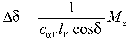
- Gemäß noch einer weiteren Alternative, die in Verfahrensschritt 9 repräsentiert ist, wird ein aktives Vorderachs-Lenksystem angesteuert, bei dem als Funktion des gewünschten Giermoment-Verlaufs Mz ein Zusatzlenkwinkel Δδ gemäß der Funktion
- Außerdem ist es auch möglich, für den Fall, dass das Kraftfahrzeug mit einem aktiven Hinterachs-Lenksystem ausgestattet ist, dieses anzusteuern (Verfahrensschritt 10). Zu diesem Zweck wird im Hinterachs-Lenksystem ein Zusatzlenkwinkel ΔδR gemäß der Funktion

- Zur Erzeugung des Gierimpulses bzw. der Änderung Δω der Gierrate ψ̇ wird, wie in dem Verlauf nach
Fig. 2 dargestellt, die Fläche unter dem gewünschten Verlauf des Giermoments MZ gemäß folgender Funktion aufintegriert: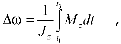
- Die Integration des Giermoments Mz erfolgt zwischen den zwei Zeitpunkten t1 und t3, zwischen denen im Ausführungsbeispiel nach
Fig. 2 ein Giermoment >0 bestehen soll. - Eingetragen ist in
Fig. 2 auch in symbolischer Weise ein mit Bezugszeichen 11 gekennzeichnetes Ereignis, welches zum Zeitpunkt t0 stattfindet und das die Unfallerkennung repräsentiert, die in der Unfalldetektionseinrichtung im Kraftfahrzeug durchgeführt wird. Der mit At, gekennzeichnete Zeitraum zwischen dem Erkennen des Unfalls zum Zeitpunkt t0 und dem Aufbau des Gierimpulses zum Zeitpunkt t1 stellt die Totzeit dar, die systembedingt ist und bis zum Erzeugen der Warnung in Form des Gierimpulses verstreicht. Die Totzeit kann durch Zusammenwirken verschiedener Stellsysteme verringert werden. - Im Ausführungsbeispiel nimmt das Giermoment Mz einen dreieckförmigen Verlauf ein, wobei die Katheten 12 und 13 des Giermoment-Dreiecks den Aufbaugradient bzw. den Rückführgradient für den Aufbau bzw. die Reduzierung des Gierimpulses darstellen. Der höchste Punkt 14 entspricht der Impulshöhe. Die Gradienten 12 oder 13 sind zeitabhängig und können nach unterschiedlichen Kriterien erzeugt werden, beispielsweise zeitabhängig maximiert werden, um eine möglichst schlagartige Änderung Δω der Gierrate ψ̇ in Form eines angenäherten Einzelimpulses zu erreichen.
Claims (19)
- Verfahren zur Warnung des Fahrers eines Kraftfahrzeugs, das mit einer Unfalldetektionseinrichtung ausgestattet ist, wobei im Falle einer erhöhten Unfallgefahr zur Warnung des Fahrers mindestens eine Fahrzustandsgröße im Kraftfahrzeug verändert wird,
dadurch gekennzeichnet, dass die zu ändernde Fahrzustandsgröße die Gierrate (ψ̇) bzw. eine damit korrelierende Zustandsgröße ist, wobei die Warnung derart ausgestattet ist, dass es sich dabei um einen Gierratenimpuls mit einer schlagartigen Änderung der Gierrate handelt, welcher jedoch an sich keinen oder zumindest keinen wesentlichen Einfluss auf die Querdynamik des Kraftfahrzeugs hat. - Verfahren nach Anspruch 1,
dadurch gekennzeichnet, dass die Änderung (Δω) der Gierrate (ψ̇) unterhalb eines vorgegebenen bzw. berechneten oberen Grenzwerts liegt. - Verfahren nach Anspruch 1 oder 2,
dadurch gekennzeichnet, dass die Änderung (Δω) der Gierrate (ψ̇) mit der Unfallwahrscheinlichkeit und/oder der zu erwartenden Unfallschwere korreliert. - Verfahren nach einem der Ansprüche 1 bis 3,
dadurch gekennzeichnet, dass die Gierrate (ψ̇) nur für den Fall geändert wird, dass die Wahrscheinlichkeit des prognostizierten Unfalls einen Schwellenwert überschreitet. - Verfahren nach einem der Ansprüche 1 bis 4,
dadurch gekennzeichnet, dass die Änderung (Δω) der Gierrate (ψ̇) oberhalb eines vorgegebenen bzw. berechneten unteren Grenzwerts liegt. - Verfahren nach einem der Ansprüche 1 bis 5,
dadurch gekennzeichnet, dass der zeitabhängige Aufbaugradient, mit dem die Gierrate (ψ̇) erhöht wird, maximiert wird. - Verfahren nach einem der Ansprüche 1 bis 6,
dadurch gekennzeichnet, dass der zeitabhängige Rückführgradient, mit dem die Gierrate (ψ̇) wieder abgesenkt wird, maximiert wird. - Verfahren nach einem der Ansprüche 1 bis 7,
dadurch gekennzeichnet, dass die Gierrate (ψ̇) zur Warnung des Fahrers nur in stabilen Fahrzuständen geändert wird. - Verfahren nach Anspruch 8,
dadurch gekennzeichnet, dass die Gierrate (ψ̇) nur geändert wird, wenn der Schwimmwinkel des Kraftfahrzeugs unterhalb eines zulässigen Grenzwerts liegt. - Verfahren nach einem der Ansprüche 1 bis 9,
dadurch gekennzeichnet, dass die Gierrate (ψ̇) als Funktion des Trägheitsmoments (J2) des Fahrzeugs um die Hochachse geändert wird. - Verfahren nach einem der Ansprüche 1 bis 10,
dadurch gekennzeichnet, dass die Gierrate (ψ̇) als Funktion des Giermoments (Mz) um die Hochachse geändert wird. - Verfahren nach Anspruch 10 und 11,
dadurch gekennzeichnet, dass die Änderung (Δω) der Gierrate (ψ̇) gemäß folgender Funktion durchgeführt wird:
- Verfahren nach einem der Ansprüche 1 bis 12,
dadurch gekennzeichnet, dass mindestens ein Fahrzeugrad zur Änderung (Δω) der Gierrate (ψ̇) abgebremst wird. - Verfahren nach einem der Ansprüche 1 bis 13,
dadurch gekennzeichnet, dass Antriebsmomente durch Beaufschlagung aktiver Stellglieder zwischen verschiedenen Fahrzeugrädern zur Änderung der Gierrate (ψ̇) verteilt werden. - Verfahren nach einem der Ansprüche 1 bis 14,
dadurch gekennzeichnet, dass die Gierrate (ψ̇) durch Erzeugung eines Zusatzlenkwinkels in einem aktiven Lenksystem geändert wird. - Verfahren nach Anspruch 15,
dadurch gekennzeichnet, dass der Zusatzlenkwinkel in einem aktiven Vorderachs-Lenksystem eingestellt wird. - Verfahren nach Anspruch 15 oder 16,
dadurch gekennzeichnet, dass der Zusatzlenkwinkel in einem aktiven Hinterachs-Lenksystem eingestellt wird. - Verfahren nach einem der Ansprüche 1 bis 17,
dadurch gekennzeichnet, dass der Gierwinkel (ψ̇) so verstellt wird, dass ein Unfall vermieden oder zumindest die Unfallfolgen reduziert werden. - Vorrichtung zur Warnung des Fahrers eines Kraftfahrzeugs, mit einer Unfalldetektionseinrichtung, wobei im Falle einer erhöhten Unfallgefahr zur Warnung des Fahrers eine Stelleinrichtung im Kraftfahrzeug betätigt wird zur Änderung (Δω) der Gierrate (ψ̇) bzw. einer mit der Gierrate korrelierenden Zustandsgröße, wobei die Warnung derart ausgestattet ist, dass es sich dabei um einen Gierratenimpuls mit einer schlagartigen Änderung der Gierrate handelt, welcher jedoch an sich keinen oder zumindest keinen wesentlichen Einfluss auf die Querdynamik des Kraftfahrzeugs hat.
Applications Claiming Priority (2)
| Application Number | Priority Date | Filing Date | Title |
|---|---|---|---|
| DE102007043604A DE102007043604A1 (de) | 2007-09-13 | 2007-09-13 | Verfahren zur Warnung des Fahrers eines Kraftfahrzeugs bei erhöhter Unfallgefahr |
| PCT/EP2008/061851 WO2009037139A1 (de) | 2007-09-13 | 2008-09-08 | Verfahren zur warnung des fahrers eines kraftfahrzeugs bei erhöhter unfallgefahr |
Publications (2)
| Publication Number | Publication Date |
|---|---|
| EP2190704A1 EP2190704A1 (de) | 2010-06-02 |
| EP2190704B1 true EP2190704B1 (de) | 2015-11-18 |
Family
ID=40223733
Family Applications (1)
| Application Number | Title | Priority Date | Filing Date |
|---|---|---|---|
| EP08803820.3A Not-in-force EP2190704B1 (de) | 2007-09-13 | 2008-09-08 | Verfahren zur warnung des fahrers eines kraftfahrzeugs bei erhöhter unfallgefahr |
Country Status (5)
| Country | Link |
|---|---|
| US (1) | US8508351B2 (de) |
| EP (1) | EP2190704B1 (de) |
| JP (1) | JP2010538383A (de) |
| DE (1) | DE102007043604A1 (de) |
| WO (1) | WO2009037139A1 (de) |
Cited By (1)
| Publication number | Priority date | Publication date | Assignee | Title |
|---|---|---|---|---|
| DE102016215793A1 (de) | 2016-08-23 | 2018-03-01 | Schaeffler Technologies AG & Co. KG | Fahrzeug sowie Verfahren zum Lenken des Fahrzeugs |
Families Citing this family (10)
| Publication number | Priority date | Publication date | Assignee | Title |
|---|---|---|---|---|
| US10511887B2 (en) * | 2010-08-30 | 2019-12-17 | Saturn Licensing Llc | Reception apparatus, reception method, transmission apparatus, transmission method, program, and broadcasting system |
| US20130311075A1 (en) * | 2012-05-18 | 2013-11-21 | Continental Automotive Systems, Inc. | Motorcycle and helmet providing advance driver assistance |
| DE102012221319A1 (de) * | 2012-11-22 | 2014-05-22 | Robert Bosch Gmbh | Verfahren und Vorrichtung zum Spannungsfreischalten eines Hochvoltnetzes eines Elektrofahrzeuges |
| DE102013009424A1 (de) * | 2013-06-04 | 2014-12-04 | Volkswagen Aktiengesellschaft | Notfallassistenz ohne aktivierte Querführungsunterstützung |
| DE102013009339A1 (de) * | 2013-06-04 | 2014-12-04 | Volkswagen Aktiengesellschaft | Verfahren und Vorrichtung zur Notfallassistenz |
| DE102013009400A1 (de) * | 2013-06-04 | 2014-12-04 | Volkswagen Aktiengesellschaft | Notfallassistenz zur Fahrzeugführung |
| DE102015215079A1 (de) | 2015-08-06 | 2017-02-09 | Zf Friedrichshafen Ag | Übernahmewarnung bei autonom gesteuertem Kraftfahrzeug |
| EP3246210B1 (de) * | 2016-05-17 | 2018-12-26 | Volvo Car Corporation | System und verfahren zur aktivierung von signalleuchten von fahrzeugen |
| DE102016007782A1 (de) | 2016-06-24 | 2017-12-28 | GM Global Technology Operations LLC (n. d. Ges. d. Staates Delaware) | Signalisierverfahren und -vorrichtung |
| US10274338B2 (en) | 2016-12-11 | 2019-04-30 | International Business Machines Corporation | Risk situations for vehicle occupants based on data provided by vehicle sensors and contextual information |
Citations (1)
| Publication number | Priority date | Publication date | Assignee | Title |
|---|---|---|---|---|
| US20040252020A1 (en) * | 2003-05-28 | 2004-12-16 | Nissan Motor Co., Ltd. | Warning system with vibration and lane deviation prevention system with the warning system for automotive vehicle |
Family Cites Families (9)
| Publication number | Priority date | Publication date | Assignee | Title |
|---|---|---|---|---|
| DE19812238A1 (de) * | 1998-03-20 | 1999-09-23 | Daimler Chrysler Ag | Verfahren zur Regelung des Gierverhaltens von Fahrzeugen |
| JP4007723B2 (ja) * | 1999-06-16 | 2007-11-14 | 本田技研工業株式会社 | 車両の走行安全装置 |
| JP3736340B2 (ja) * | 2000-12-14 | 2006-01-18 | トヨタ自動車株式会社 | 車両制御装置 |
| DE10235414A1 (de) * | 2002-08-02 | 2004-02-12 | Robert Bosch Gmbh | Verfahren und Vorrichtung zur Ermittlung des Bevorstehens einer unausweichbaren Kollision |
| DE10244205A1 (de) * | 2002-09-23 | 2004-03-25 | Robert Bosch Gmbh | Verfahren und Einrichtung zur Verhinderung der Kollision von Fahrzeugen |
| DE10343683A1 (de) * | 2003-09-20 | 2005-04-21 | Daimler Chrysler Ag | Informationssystem für Kraftfahrzeuge |
| JP4042980B2 (ja) * | 2004-05-14 | 2008-02-06 | 本田技研工業株式会社 | 車両操作支援装置 |
| DE102004030756A1 (de) | 2004-06-25 | 2006-01-19 | Robert Bosch Gmbh | Verfahren und Vorrichtung zur kinästhetischen Warnung des Fahrers eines Kraftfahrzeugs |
| JP2007145152A (ja) * | 2005-11-28 | 2007-06-14 | Mitsubishi Electric Corp | 車両用自動制動装置 |
-
2007
- 2007-09-13 DE DE102007043604A patent/DE102007043604A1/de not_active Withdrawn
-
2008
- 2008-09-08 EP EP08803820.3A patent/EP2190704B1/de not_active Not-in-force
- 2008-09-08 WO PCT/EP2008/061851 patent/WO2009037139A1/de active Application Filing
- 2008-09-08 US US12/733,654 patent/US8508351B2/en not_active Expired - Fee Related
- 2008-09-08 JP JP2010523526A patent/JP2010538383A/ja active Pending
Patent Citations (1)
| Publication number | Priority date | Publication date | Assignee | Title |
|---|---|---|---|---|
| US20040252020A1 (en) * | 2003-05-28 | 2004-12-16 | Nissan Motor Co., Ltd. | Warning system with vibration and lane deviation prevention system with the warning system for automotive vehicle |
Cited By (3)
| Publication number | Priority date | Publication date | Assignee | Title |
|---|---|---|---|---|
| DE102016215793A1 (de) | 2016-08-23 | 2018-03-01 | Schaeffler Technologies AG & Co. KG | Fahrzeug sowie Verfahren zum Lenken des Fahrzeugs |
| DE102016215793B4 (de) * | 2016-08-23 | 2018-04-26 | Schaeffler Technologies AG & Co. KG | Fahrzeug sowie Verfahren zum Lenken des Fahrzeugs |
| US11124179B2 (en) | 2016-08-23 | 2021-09-21 | Schaeffler Technologies AG & Co. KG | Vehicle and method for steering the vehicle |
Also Published As
| Publication number | Publication date |
|---|---|
| US20110001617A1 (en) | 2011-01-06 |
| DE102007043604A1 (de) | 2009-03-19 |
| EP2190704A1 (de) | 2010-06-02 |
| JP2010538383A (ja) | 2010-12-09 |
| WO2009037139A1 (de) | 2009-03-26 |
| US8508351B2 (en) | 2013-08-13 |
Similar Documents
| Publication | Publication Date | Title |
|---|---|---|
| EP2190704B1 (de) | Verfahren zur warnung des fahrers eines kraftfahrzeugs bei erhöhter unfallgefahr | |
| EP2340189B1 (de) | Verfahren zur einstellung eines bremssystems eines fahrzeugs im falle einer kollision | |
| EP1843924B1 (de) | Verfahren und vorrichtung zur vermeidung und/oder minderung der folgen von kollisionen beim ausweichen vor hindernissen | |
| EP2758291B1 (de) | Fahrerassistenzsystem mit autonomer bremsung bis zum stillstand | |
| EP1868852B1 (de) | Verfahren und vorrichtung zur stabilisierung eines fahrzeugs nach einer kollision | |
| EP1687183B1 (de) | Verfahren und einrichtung zur verringerung von unfallschäden | |
| EP2013069B1 (de) | Verfahren und vorrichtung zum ermitteln eines optimalen lenkwinkels in untersteuersituationen eines fahrzeugs | |
| EP3079957B1 (de) | Verfahren zur regelung der fahrstabilität | |
| DE102009028880A1 (de) | Fahrtrichtungsstabilisierungssystem für Fahrzeuge | |
| WO2006061276A1 (de) | Verfahren und vorrichtung zur fahrzeugverzögerung nach einer kollision | |
| EP3328693B1 (de) | Verfahren zur fahrerunterstützung bei wasserglätte auf einem fahrbahnuntergrund | |
| DE102008010667B4 (de) | Verfahren und Vorrichtung zum Unterstützen eines Fahrzeugbedieners | |
| EP3544868A1 (de) | Verfahren und steuergerät zum erkennen von kritischen fahrsituationen eines kraftzweirads | |
| DE102005005412B4 (de) | Vorrichtung und Verfahren zur Vermeidung von Gegenverkehrsunfällen eines Fahrzeugs nach einem Heckaufprall | |
| EP1884450B1 (de) | Fahrdynamikregler mit einem in der Lenkung angeordneten Drehmomentensensor | |
| EP1912816B1 (de) | Verfahren zur steuerung eines gurtstraffers und sicherheitsanordnung mit einem gurtstraffer | |
| EP2349797B1 (de) | Verfahren zur einstellung eines bremssystems eines fahrzeugs | |
| WO2009040255A1 (de) | Verfahren zur beeinflussung der bewegung eines fahrzeugs | |
| DE102011107271B4 (de) | Verfahren und Vorrichtung zur Steuerung einer Bremse eines Fahrzeugs sowie Fahrzeug | |
| DE102010003099A1 (de) | Fahrspurwechselassistenzverfahren für ein Kraftfahrzeug | |
| DE102016219340B4 (de) | Kraftfahrzeug mit einem steuerbaren Fahrwerk und Verfahren zum Betreiben eines Kraftfahrzeugs | |
| WO2013120484A2 (de) | Verfahren zur steuerung eines kraftfahrzeugs während und unmittelbar nach einer flugphase | |
| DE10316253B4 (de) | Verfahren zum Modifizieren einer Fahrstabilitätsregelung eines Fahrzeugs | |
| EP2207693A1 (de) | Verfahren zur unfallfolgenminderung bei kraftfahrzeugen |
Legal Events
| Date | Code | Title | Description |
|---|---|---|---|
| PUAI | Public reference made under article 153(3) epc to a published international application that has entered the european phase |
Free format text: ORIGINAL CODE: 0009012 |
|
| 17P | Request for examination filed |
Effective date: 20100413 |
|
| AK | Designated contracting states |
Kind code of ref document: A1 Designated state(s): AT BE BG CH CY CZ DE DK EE ES FI FR GB GR HR HU IE IS IT LI LT LU LV MC MT NL NO PL PT RO SE SI SK TR |
|
| AX | Request for extension of the european patent |
Extension state: AL BA MK RS |
|
| DAX | Request for extension of the european patent (deleted) | ||
| 17Q | First examination report despatched |
Effective date: 20120222 |
|
| GRAP | Despatch of communication of intention to grant a patent |
Free format text: ORIGINAL CODE: EPIDOSNIGR1 |
|
| INTG | Intention to grant announced |
Effective date: 20150821 |
|
| GRAS | Grant fee paid |
Free format text: ORIGINAL CODE: EPIDOSNIGR3 |
|
| GRAA | (expected) grant |
Free format text: ORIGINAL CODE: 0009210 |
|
| AK | Designated contracting states |
Kind code of ref document: B1 Designated state(s): AT BE BG CH CY CZ DE DK EE ES FI FR GB GR HR HU IE IS IT LI LT LU LV MC MT NL NO PL PT RO SE SI SK TR |
|
| REG | Reference to a national code |
Ref country code: GB Ref legal event code: FG4D Free format text: NOT ENGLISH |
|
| REG | Reference to a national code |
Ref country code: CH Ref legal event code: EP |
|
| REG | Reference to a national code |
Ref country code: AT Ref legal event code: REF Ref document number: 761383 Country of ref document: AT Kind code of ref document: T Effective date: 20151215 |
|
| REG | Reference to a national code |
Ref country code: IE Ref legal event code: FG4D Free format text: LANGUAGE OF EP DOCUMENT: GERMAN |
|
| REG | Reference to a national code |
Ref country code: DE Ref legal event code: R096 Ref document number: 502008013608 Country of ref document: DE |
|
| REG | Reference to a national code |
Ref country code: SE Ref legal event code: TRGR |
|
| REG | Reference to a national code |
Ref country code: NL Ref legal event code: MP Effective date: 20160218 |
|
| REG | Reference to a national code |
Ref country code: LT Ref legal event code: MG4D |
|
| PG25 | Lapsed in a contracting state [announced via postgrant information from national office to epo] |
Ref country code: HR Free format text: LAPSE BECAUSE OF FAILURE TO SUBMIT A TRANSLATION OF THE DESCRIPTION OR TO PAY THE FEE WITHIN THE PRESCRIBED TIME-LIMIT Effective date: 20151118 Ref country code: IT Free format text: LAPSE BECAUSE OF FAILURE TO SUBMIT A TRANSLATION OF THE DESCRIPTION OR TO PAY THE FEE WITHIN THE PRESCRIBED TIME-LIMIT Effective date: 20151118 Ref country code: IS Free format text: LAPSE BECAUSE OF FAILURE TO SUBMIT A TRANSLATION OF THE DESCRIPTION OR TO PAY THE FEE WITHIN THE PRESCRIBED TIME-LIMIT Effective date: 20160318 Ref country code: ES Free format text: LAPSE BECAUSE OF FAILURE TO SUBMIT A TRANSLATION OF THE DESCRIPTION OR TO PAY THE FEE WITHIN THE PRESCRIBED TIME-LIMIT Effective date: 20151118 Ref country code: NL Free format text: LAPSE BECAUSE OF FAILURE TO SUBMIT A TRANSLATION OF THE DESCRIPTION OR TO PAY THE FEE WITHIN THE PRESCRIBED TIME-LIMIT Effective date: 20151118 Ref country code: NO Free format text: LAPSE BECAUSE OF FAILURE TO SUBMIT A TRANSLATION OF THE DESCRIPTION OR TO PAY THE FEE WITHIN THE PRESCRIBED TIME-LIMIT Effective date: 20160218 Ref country code: LT Free format text: LAPSE BECAUSE OF FAILURE TO SUBMIT A TRANSLATION OF THE DESCRIPTION OR TO PAY THE FEE WITHIN THE PRESCRIBED TIME-LIMIT Effective date: 20151118 |
|
| PG25 | Lapsed in a contracting state [announced via postgrant information from national office to epo] |
Ref country code: FI Free format text: LAPSE BECAUSE OF FAILURE TO SUBMIT A TRANSLATION OF THE DESCRIPTION OR TO PAY THE FEE WITHIN THE PRESCRIBED TIME-LIMIT Effective date: 20151118 Ref country code: PT Free format text: LAPSE BECAUSE OF FAILURE TO SUBMIT A TRANSLATION OF THE DESCRIPTION OR TO PAY THE FEE WITHIN THE PRESCRIBED TIME-LIMIT Effective date: 20160318 Ref country code: GR Free format text: LAPSE BECAUSE OF FAILURE TO SUBMIT A TRANSLATION OF THE DESCRIPTION OR TO PAY THE FEE WITHIN THE PRESCRIBED TIME-LIMIT Effective date: 20160219 Ref country code: LV Free format text: LAPSE BECAUSE OF FAILURE TO SUBMIT A TRANSLATION OF THE DESCRIPTION OR TO PAY THE FEE WITHIN THE PRESCRIBED TIME-LIMIT Effective date: 20151118 Ref country code: PL Free format text: LAPSE BECAUSE OF FAILURE TO SUBMIT A TRANSLATION OF THE DESCRIPTION OR TO PAY THE FEE WITHIN THE PRESCRIBED TIME-LIMIT Effective date: 20151118 |
|
| PG25 | Lapsed in a contracting state [announced via postgrant information from national office to epo] |
Ref country code: CZ Free format text: LAPSE BECAUSE OF FAILURE TO SUBMIT A TRANSLATION OF THE DESCRIPTION OR TO PAY THE FEE WITHIN THE PRESCRIBED TIME-LIMIT Effective date: 20151118 |
|
| REG | Reference to a national code |
Ref country code: DE Ref legal event code: R097 Ref document number: 502008013608 Country of ref document: DE |
|
| PG25 | Lapsed in a contracting state [announced via postgrant information from national office to epo] |
Ref country code: RO Free format text: LAPSE BECAUSE OF FAILURE TO SUBMIT A TRANSLATION OF THE DESCRIPTION OR TO PAY THE FEE WITHIN THE PRESCRIBED TIME-LIMIT Effective date: 20151118 Ref country code: DK Free format text: LAPSE BECAUSE OF FAILURE TO SUBMIT A TRANSLATION OF THE DESCRIPTION OR TO PAY THE FEE WITHIN THE PRESCRIBED TIME-LIMIT Effective date: 20151118 Ref country code: SK Free format text: LAPSE BECAUSE OF FAILURE TO SUBMIT A TRANSLATION OF THE DESCRIPTION OR TO PAY THE FEE WITHIN THE PRESCRIBED TIME-LIMIT Effective date: 20151118 Ref country code: EE Free format text: LAPSE BECAUSE OF FAILURE TO SUBMIT A TRANSLATION OF THE DESCRIPTION OR TO PAY THE FEE WITHIN THE PRESCRIBED TIME-LIMIT Effective date: 20151118 |
|
| REG | Reference to a national code |
Ref country code: FR Ref legal event code: PLFP Year of fee payment: 9 |
|
| PLBE | No opposition filed within time limit |
Free format text: ORIGINAL CODE: 0009261 |
|
| STAA | Information on the status of an ep patent application or granted ep patent |
Free format text: STATUS: NO OPPOSITION FILED WITHIN TIME LIMIT |
|
| 26N | No opposition filed |
Effective date: 20160819 |
|
| PG25 | Lapsed in a contracting state [announced via postgrant information from national office to epo] |
Ref country code: SI Free format text: LAPSE BECAUSE OF FAILURE TO SUBMIT A TRANSLATION OF THE DESCRIPTION OR TO PAY THE FEE WITHIN THE PRESCRIBED TIME-LIMIT Effective date: 20151118 |
|
| PG25 | Lapsed in a contracting state [announced via postgrant information from national office to epo] |
Ref country code: BE Free format text: LAPSE BECAUSE OF NON-PAYMENT OF DUE FEES Effective date: 20160930 |
|
| PG25 | Lapsed in a contracting state [announced via postgrant information from national office to epo] |
Ref country code: MC Free format text: LAPSE BECAUSE OF FAILURE TO SUBMIT A TRANSLATION OF THE DESCRIPTION OR TO PAY THE FEE WITHIN THE PRESCRIBED TIME-LIMIT Effective date: 20151118 |
|
| REG | Reference to a national code |
Ref country code: CH Ref legal event code: PL |
|
| REG | Reference to a national code |
Ref country code: IE Ref legal event code: MM4A |
|
| PG25 | Lapsed in a contracting state [announced via postgrant information from national office to epo] |
Ref country code: LI Free format text: LAPSE BECAUSE OF NON-PAYMENT OF DUE FEES Effective date: 20160930 Ref country code: CH Free format text: LAPSE BECAUSE OF NON-PAYMENT OF DUE FEES Effective date: 20160930 Ref country code: IE Free format text: LAPSE BECAUSE OF NON-PAYMENT OF DUE FEES Effective date: 20160908 |
|
| PG25 | Lapsed in a contracting state [announced via postgrant information from national office to epo] |
Ref country code: LU Free format text: LAPSE BECAUSE OF NON-PAYMENT OF DUE FEES Effective date: 20160908 |
|
| REG | Reference to a national code |
Ref country code: FR Ref legal event code: PLFP Year of fee payment: 10 |
|
| REG | Reference to a national code |
Ref country code: AT Ref legal event code: MM01 Ref document number: 761383 Country of ref document: AT Kind code of ref document: T Effective date: 20160908 |
|
| REG | Reference to a national code |
Ref country code: BE Ref legal event code: MM Effective date: 20160930 |
|
| PG25 | Lapsed in a contracting state [announced via postgrant information from national office to epo] |
Ref country code: AT Free format text: LAPSE BECAUSE OF NON-PAYMENT OF DUE FEES Effective date: 20160908 |
|
| PG25 | Lapsed in a contracting state [announced via postgrant information from national office to epo] |
Ref country code: HU Free format text: LAPSE BECAUSE OF FAILURE TO SUBMIT A TRANSLATION OF THE DESCRIPTION OR TO PAY THE FEE WITHIN THE PRESCRIBED TIME-LIMIT; INVALID AB INITIO Effective date: 20080908 Ref country code: CY Free format text: LAPSE BECAUSE OF FAILURE TO SUBMIT A TRANSLATION OF THE DESCRIPTION OR TO PAY THE FEE WITHIN THE PRESCRIBED TIME-LIMIT Effective date: 20151118 |
|
| PG25 | Lapsed in a contracting state [announced via postgrant information from national office to epo] |
Ref country code: TR Free format text: LAPSE BECAUSE OF FAILURE TO SUBMIT A TRANSLATION OF THE DESCRIPTION OR TO PAY THE FEE WITHIN THE PRESCRIBED TIME-LIMIT Effective date: 20151118 Ref country code: MT Free format text: LAPSE BECAUSE OF FAILURE TO SUBMIT A TRANSLATION OF THE DESCRIPTION OR TO PAY THE FEE WITHIN THE PRESCRIBED TIME-LIMIT Effective date: 20151118 |
|
| PG25 | Lapsed in a contracting state [announced via postgrant information from national office to epo] |
Ref country code: BG Free format text: LAPSE BECAUSE OF FAILURE TO SUBMIT A TRANSLATION OF THE DESCRIPTION OR TO PAY THE FEE WITHIN THE PRESCRIBED TIME-LIMIT Effective date: 20151118 |
|
| REG | Reference to a national code |
Ref country code: FR Ref legal event code: PLFP Year of fee payment: 11 |
|
| PGFP | Annual fee paid to national office [announced via postgrant information from national office to epo] |
Ref country code: FR Payment date: 20180921 Year of fee payment: 11 |
|
| PGFP | Annual fee paid to national office [announced via postgrant information from national office to epo] |
Ref country code: SE Payment date: 20180924 Year of fee payment: 11 Ref country code: GB Payment date: 20180924 Year of fee payment: 11 |
|
| PGFP | Annual fee paid to national office [announced via postgrant information from national office to epo] |
Ref country code: DE Payment date: 20191125 Year of fee payment: 12 |
|
| PG25 | Lapsed in a contracting state [announced via postgrant information from national office to epo] |
Ref country code: SE Free format text: LAPSE BECAUSE OF NON-PAYMENT OF DUE FEES Effective date: 20190909 |
|
| REG | Reference to a national code |
Ref country code: SE Ref legal event code: EUG |
|
| GBPC | Gb: european patent ceased through non-payment of renewal fee |
Effective date: 20190908 |
|
| PG25 | Lapsed in a contracting state [announced via postgrant information from national office to epo] |
Ref country code: FR Free format text: LAPSE BECAUSE OF NON-PAYMENT OF DUE FEES Effective date: 20190930 Ref country code: GB Free format text: LAPSE BECAUSE OF NON-PAYMENT OF DUE FEES Effective date: 20190908 |
|
| REG | Reference to a national code |
Ref country code: DE Ref legal event code: R119 Ref document number: 502008013608 Country of ref document: DE |
|
| PG25 | Lapsed in a contracting state [announced via postgrant information from national office to epo] |
Ref country code: DE Free format text: LAPSE BECAUSE OF NON-PAYMENT OF DUE FEES Effective date: 20210401 |