EP2190588B1 - Procédé d'alimentation de poudre, appareil d'alimentation de poudre et appareil de revêtement par pulvérisation électrostatique de poudre - Google Patents
Procédé d'alimentation de poudre, appareil d'alimentation de poudre et appareil de revêtement par pulvérisation électrostatique de poudre Download PDFInfo
- Publication number
- EP2190588B1 EP2190588B1 EP08807017A EP08807017A EP2190588B1 EP 2190588 B1 EP2190588 B1 EP 2190588B1 EP 08807017 A EP08807017 A EP 08807017A EP 08807017 A EP08807017 A EP 08807017A EP 2190588 B1 EP2190588 B1 EP 2190588B1
- Authority
- EP
- European Patent Office
- Prior art keywords
- powder
- feed
- valve
- intake valve
- feed chamber
- Prior art date
- Legal status (The legal status is an assumption and is not a legal conclusion. Google has not performed a legal analysis and makes no representation as to the accuracy of the status listed.)
- Active
Links
- 239000000843 powder Substances 0.000 title claims description 168
- 238000000034 method Methods 0.000 title claims description 11
- 238000005507 spraying Methods 0.000 title claims description 7
- 229940098458 powder spray Drugs 0.000 title claims description 3
- 239000011248 coating agent Substances 0.000 claims description 30
- 238000000576 coating method Methods 0.000 claims description 30
- 239000007921 spray Substances 0.000 claims description 2
- 239000000463 material Substances 0.000 description 3
- 239000004482 other powder Substances 0.000 description 2
- 238000005086 pumping Methods 0.000 description 2
- 230000004931 aggregating effect Effects 0.000 description 1
- 230000005540 biological transmission Effects 0.000 description 1
- 230000001419 dependent effect Effects 0.000 description 1
- 238000006073 displacement reaction Methods 0.000 description 1
Images

Classifications
-
- B—PERFORMING OPERATIONS; TRANSPORTING
- B05—SPRAYING OR ATOMISING IN GENERAL; APPLYING FLUENT MATERIALS TO SURFACES, IN GENERAL
- B05B—SPRAYING APPARATUS; ATOMISING APPARATUS; NOZZLES
- B05B7/00—Spraying apparatus for discharge of liquids or other fluent materials from two or more sources, e.g. of liquid and air, of powder and gas
- B05B7/14—Spraying apparatus for discharge of liquids or other fluent materials from two or more sources, e.g. of liquid and air, of powder and gas designed for spraying particulate materials
- B05B7/1404—Arrangements for supplying particulate material
- B05B7/1459—Arrangements for supplying particulate material comprising a chamber, inlet and outlet valves upstream and downstream the chamber and means for alternately sucking particulate material into and removing particulate material from the chamber through the valves
Definitions
- the present invention relates to a powder feeding method, to a powder feeding device and to an electrostatical powder spraycoating apparatus comprising a powder feeding device.
- Dense phase powder pumps comprise at least one feed chamber fitted with a powder intake valve and a powder outlet valve.
- the chamber may be connected alternatively to a vacuum source to aspirate powder, through its open powder intake valve while the powder outlet valve is closed, into the feed chamber, or subsequently thereto to a source of compressed gas, usually compressed air, in order to expel the coating powder from the feed chamber through the open powder outlet valve while the powder intake valve is closed.
- a source of compressed gas usually compressed air
- injectors aspirate coating powder into a flow of feeding air where said powder mixed with this flow and is fed through a discharge conduit to a powder spraycoating tool Such powder spraycoating equipment is known for instance from the European patent document EP 0606577 B1 .
- the dense phase powder pumps are fitted with at least one, usually two feed chambers.
- a vacuum intake of the feed chamber -- in some designs also a compressed air intake in the feed chamber - is fitted with a filter permeable to air but not to coating powder.
- the filter material has conventionally been a sintered material.
- the powder intake and outlet valves are pinch valves that have already been successfully used with injector pumps in feeding thin phase powders because being less susceptible to aggregating powder within them and being more easily cleansed by the gas flow through them than are other types of valves.
- a coating powder feed method and a corresponding device according to the preamble of claims 1 and 7 is known from US 2005/0207901 A1 .
- the object of the present invention is to increase the pumping rate without incurring thereby complex or costly steps.
- the invention allows raising the pumping rate in simple manner.
- the present invention allows more accurately metering the powder feed volume rates.
- a control signal is generated to produce the partial vacuum in the feed chamber a predetermined delay after a control signal opening the powder intake valve was generated, as a result of which the partial vacuum begins increasing in the feed chamber after the above cited delay time beyond opening the powder intake valve.
- the predetermined delay time preferably shall be in the range of 0 to 50 ms for a feed-cycle period of about 200 ms of the feed chamber.
- this embodiment mode does not preclude applying the present invention to other delay times and cycle-periods.
- the present invention attains that the partial vacuum in the feed chamber shall oppose an opening displacement of the powder intake valve -- especially it is a pinch valve -- at least at the time the powder intake valve starts opening, than is the case in the state of the art.
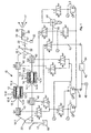
- Fig. 1 schematically shows a coating powder feeding device of the invention containing a dense phase powder pump 10 illustratively fitted with two feed chambers 12 and 14 configured in parallel each in a pump cylinder A respectively B each fitted with a powder intake valve Q1 and Q2 at a powder intake 12.1 and 14.1 and with a powder outlet valve Q3 and Q4 respectively at a powder outlet 12.2 and 12. 4.
- the powder intake valves Q1 and Q2 are shown away from the powder intakes 12.1 respectively 14.1, though in fact they are configured preferably immediately at the powder intakes 12.1 and 14.1.
- the powder outlet valves Q3 and Q4 respectively are shown away from the powder outlets 12.2 and 14.2 for clarity, though practically they are preferably mounted immediately at the powder outlets 12.2 and 14.2.
- each feed chamber 12 and 14 is constituted -- at least over part of its straight length between its powder intake valve Q1 respectively Q2 and its powder outlet valve Q3 and Q4 - by a filter 12.4 and 14.4 enclosing the feed chamber 12 and 14 and separating it from an intermediate chamber 12.5 and 14.5.
- the intermediate chamber 12.5 and 14.5 encloses the filter 12.4 and 14. 4 and is situated in a pump housing 12.6 and 14.6.
- a gas hookup port 12.3 respectively 14.3 is constituted in the pump housing 12.6 and 14. 6 and issues into the intermediate chamber 12.5 and 14.5 and is connected to a connector of a control valve 1.5 and 1.6.
- This hookup port of the control valve 1.5 respectively 1.6 can be loaded alternatively with a partial vacuum or with compressed air by switching this control valve 1.5 or 1.6.
- the filter 12.4 and 14.4 is permeable to gas but impermeable to coating powder. Preferably it is porous and made of a sintered material.
- a powder moving conduit 16 is fitted with a preferably Y-shaped branch 20 with feed conduit branches 16.1 respectively 16.2 to move coating powder 17 out of a powder bin 18 and is connected to allow flow with the powder intake sides of the two powder intake valves Q1 and Q2.
- the powder outlet sides of the two powder outlet valves Q3 and Q4 each are connected by a discharge branch 22.1 respectively 22.2, preferably by a Y-shaped branch 24, to a powder discharge conduit 22.
- the powder discharge conduit 22 may lead to a powder receiving bin or to a powder coating tool 26.
- the manual or automatic spray tool 26 is fitted preferably to at least one high voltage (hv) electrode 28 to electrostatically charge the coating powder 17.
- the hv may be generated by a hv generator 30 integrated into the powder spray tool 26 and supplied from a current or voltage source 32 with electric power.
- the powder intake valves Q1 and Q2 and the powder outlet valves Q3 and Q4 preferably are pinch valves. Their designs may be identical. Using the powder intake valve Q1 as a model, Figs. 2 and 3 schematically show a preferred embodiment mode used also for all other valves Q2, Q3 and Q4. Their valve duct 34 is subtended by the inner surface of a flexible hose 36 separating the valve duct 34 from a pressure chamber 38 on the hose outer side in a housing 39. The valve duct 34 is the hose transmission aperture and is kept open by the tension in the hose 36 as shown in Fig. 2 .
- a compressed gas preferably air
- the hose When introducing a compressed gas, preferably air, into the pressure chamber 38 through a gas hookup 40, the hose is radially compressed and in this manner the valve duct 34 can be kept closed as shown in Fig. 3 .
- the compressed air is then removed from the pressure chamber 38, the hose 36 resumes its initial shape shown in Fig. 2 , wherein said valve duct 34 is open again.
- Fig. 1 shows nine control valves 1.1, 1.2, 1.3, 1.4, 1.5. 1.6, 1.7, 1.8 and 1.9 which may be driven independently from each other by an electronic control 42.
- Fig. 1 also shows three pressure regulators 2.1, 2.2 and 2.3 and a vacuum source 44.
- the vacuum source 44 preferably is a vacuum injector.
- the control valve 1.1 is connected to the powder intake valve Q1 and may alternatively may connect latter's pressure chamber 38 to a source of compressed air 46 or vent it.
- the control valve 1.2 is connected to the other powder intake valve Q2 and is able to alternatively connect its pressure chamber 38 to the compressed air feed conduit 46 or to vent it.
- the control valve 1.3 is connected the powder outlet valve Q3 and is able to alternatively connect its pressure chamber 38 to the compressed air feed conduit 46 or to vent it.
- the control valve 1.4 is connected to the other powder outlet valve Q4 and is able to alternatively connect its pressure chamber 38 to the compressed air feed conduit 46 or to vent it.
- the compressed air feed conduit 46 and the control 42 may be connected to a source of compressed air 48 either directly or by means of pressure regulators.
- one of the pressure regulators namely 2.2, is configured between the control valves 1.1, 1.2, 1.3 and 1.4 on one hand and on the other hand the compressed air feed conduit 46, the closing pressure of the pinch valves Q1, Q2, Q3 and Q4 for powder feed operation being adjustable at said pressure regulator 2.2.
- an additional pressure regulator 2.1 may be used in addition to the pressure regulator 2.2, only one of the two pressure regulators 2.2 or 2.1 being connectable alternatively by means of the control valve 1.9 to the pressure intake side of the control valves 1.1, 1.2, 1.3 and 1.4. Consequently a different air pressure may be set at the second pressure regulator 2.1 than at the pressure regulator 2.2, for instance a higher pressure.
- the higher pressure of the second pressure regulator 2.1 may serve to generate a higher closing pressure in the valves Q1, Q2, Q3 and Q4 designed as pinch valves whenever the feed chambers 12 and 14 are used not for power feeding, but for cleansing with cleansing air.
- Each pump cylinder A and B is fitted with a gas hookup port 12.3 respectively 14.3 to which is connected one of the two control valves 1.5 and 1.6 in order to supply the two feed chambers 12 and 14 alternatingly with compressed conveying air from the control 42 or to connect them to the vacuum source 44 and thereby to evacuate them.
- Compressed air from the compressed air supply conduit 46 can be fed by means of the pressure regulator 2.3 and the control valve 1.7 to a vacuum injector 44 to generate in latter a partial vacuum which can be applied by means of the two independently driven control valves 1.5 and 1.6 alternatively to either of the feed chambers 12 and 14 respectively.
- the control valve 1.7 allows alternatively connecting the vacuum injector 44 in the manner discussed above to the compressed air supply conduit 46 or to vent it.
- the feed chambers 12 and 14 can be connected by means of the control valves 1.5 and 1.6 alternatively to a partial vacuum hookup 50 of the vacuum injector 44 or by means of a compressed air conduit 52 to a compressed air outlet 54 of the control 42.
- the preferred embodiment mode of Fig. 1 further comprises the control valve 1.8 by means of which the pressure side of the two control valves 1.5 and 1.6 of the feed chambers 12 and 14 alternatively can be connected to the compressed air supply conduit 46 of which the pressure exceeds that of the compressed feed air applied by the control 42 through the compressed air feed conduit 52.
- the higher pressure of the compressed air supply conduit 46 may be applied through the control valve 1.8 to the feed chambers 12 and 14 for instance when the feed chambers 12 and 14 and the powder conduits connected to them must be rinsed with compressed air.
- control 42 generates a control signal to the control valve 1.5 or 1.6 to generate the partial vacuum in the feed chamber 12 or the other feed chamber 14, no earlier than simultaneously with a control signal to the control valve 1.1 or 1.2 opening the related powder intake valve Q1 or Q2 in such a way that the partial vacuum in the feed chamber 12 or 14 shall build up, no earlier than simultaneously with opening the powder intake valve Q1 respectively Q2 associated with this feed chamber 12 or 14.
- the control 42 generates the control signal for the control valve 1.5 or 1.6 to generate a partial vacuum in the pertinent feed chamber 12 or 14 at a predetermined time delay after the control signal has been applied to the related control valve 1.1 or 1.2 to open the powder intake valve Q1 or Q2 of the related feed chamber 12 or 14, as a result of which the partial vacuum in the pertinent feed chamber 12 or 14 shall build up at the defined time delay after opening the powder intake valve Q1 respectively Q2.
- the predetermined time delay may be stored in permanent or variable manner in the control 42 or be adjustable for any application of the feed apparatus.
- the predetermined delay time is in the range between 0 and 50 ms.
- the present invention allows diverse cleansing procedures to cleanse the various components by passing compressed air through or over them, either by a feed of compressed air from the control 42 or a feed of compressed air at a higher pressure from the compressed air supply conduit 46.
- This compressed rinsing air may be guided either through both feed chambers 12 and 14 simultaneously in the same direction or in opposite directions. Both feed chambers 12 and 14 may be cleansed individually or jointly.
- the compressed cleansing air may pass from the feed chambers 12 and 14 toward the powder discharge conduit 22 or reversely in the direction to the powder feed conduit 16.
- the powder intake valve Q1 respectively Q2 and the powder outlet valve Q3 and Q4 one and/or the other feed chamber 12 and 14 may be opened simultaneously to generate two mutually oppositely directed flows of compressed rinsing air jointly flowing through the gas hookup port 12.3 respectively 14.3.
- the flow of compressed rinsing air may be continuous or in pulses.
- pinch valves Q1, Q2, Q3 and Q4 may be used that are operated not by applying pneumatic pressure on the hose 36 to pinch it, but instead being operated by a mechanical element, for instance a plunger or the like.
- a mechanical element may be driven pneumatically, hydraulically or electrically.
- gas hookup ports 12,3 and 14.3 may be used for each feed chamber 12 respectively 14, one of which being connectable to the vacuum source 44 and the other to the compressed feed air conduit 52.
Claims (13)
- Procédé d'alimentation en poudre de revêtement, comprenant :l'utilisation d'une pompe à poudre à phase dense (10) comprenant au moins une chambre d'alimentation (12, 14) munie d'une soupape d'admission de poudre (Q1, Q2) et d'une soupape de sortie de poudre (Q3, Q4) ;la réalisation des cycles fonctionnels suivants (a) à (d) au moins une fois :(a) générer un vide partiel dans la chambre d'alimentation (12, 14) pour aspirer la poudre de revêtement dans la chambre d'alimentation (12, 14) à travers la soupape d'admission de poudre ouverte (Q1, Q2) tandis que la soupape de sortie de poudre (Q3, Q4) est fermée ;(b) fermer la soupape d'admission de poudre (Q1, Q2) et ouvrir la soupape de sortie de poudre (Q3, Q4) ;(c) introduire un gaz comprimé dans la chambre d'alimentation (12, 14) pour décharger la poudre de revêtement de la chambre d'alimentation (12, 14) à travers la soupape de sortie de poudre ouverte (Q3, Q4) tandis que la soupape d'admission de poudre (Q1, Q2) est fermée ; et(d) fermer la soupape de sortie de poudre (Q3, Q4) et ouvrir la soupape d'admission de poudre (Q1, Q2),caractérisé en ce quependant le segment (a) du cycle, ou lors du passage du segment (d) du cycle au segment (a) du cycle, un signal de commande générant le vide partiel dans la chambre d'alimentation (12, 14) est généré un temps de retard prédéterminé après la génération du signal de commande ouvrant la soupape d'admission de poudre (Q1, Q2), suite à quoi l'accumulation de vide partiel dans la chambre d'alimentation (12, 14) commence un temps de retard défini après l'ouverture de la soupape d'admission de poudre (Q1, Q2).
- Procédé d'alimentation en poudre de revêtement selon la revendication 1, caractérisé en ce qu'une soupape à manchon déformable est toujours utilisée en tant que soupape d'admission de poudre (Q1, Q2) et en tant que soupape de sortie de poudre (Q3, Q4).
- Procédé d'alimentation en poudre de revêtement selon la revendication 2, caractérisé en ce que les soupapes à manchon déformable (Q1, Q2, Q3, Q4) sont d'une conception telle qu'un tuyau flexible (36) sépare un conduit de soupape (34) sur le côté du tuyau interne d'une chambre de pression (38) sur l'extérieur du tuyau et en ce que le tuyau (36) peut être fermé par compression par la pression d'un gaz comprimé appliqué introduit dans la chambre de pression (38), fermant ainsi le conduit de soupape (34).
- Procédé d'alimentation en poudre de revêtement selon l'une quelconque des revendications précédentes, caractérisé en ce que la pompe à poudre à phase dense (10) utilisée est telle qu'elle comprend au moins deux chambres d'alimentation (12, 14) s'étendant en parallèle, chaque chambre d'alimentation (12, 14) étant munie d'une soupape d'admission de poudre (Q1, Q2) et d'une soupape de sortie de poudre (Q3, Q4) et en ce que de la poudre est aspirée en alternance dans l'une (12) des chambres d'alimentation (12, 14) par un vide partiel à travers sa soupape d'admission de poudre (Q1), et de la poudre est déchargée d'une autre (14) des chambres d'alimentation (12, 14) au moyen d'un gaz comprimé à travers sa soupape de sortie de poudre (Q4), et en ce que la poudre est ensuite déchargée par un gaz comprimé depuis ladite chambre d'alimentation (12) à travers sa soupape de sortie de poudre (Q3) et de la poudre est aspirée par un vide partiel dans l'autre chambre d'alimentation (14) à travers sa soupape d'admission de poudre (Q2).
- Procédé d'alimentation en poudre de revêtement selon l'une quelconque des revendications précédentes, caractérisé en ce que des soupapes de commande séparées (1.1, 1.2, 1.3, 1.4) sont utilisées pour chaque chambre d'alimentation (12, 14) pour commander la soupape d'admission de poudre (Q1, Q2) et la soupape de sortie de poudre (Q3, Q4) et en ce que lesdites soupapes de commande sont entraînées séparément et en ce qu'une soupape de commande séparée supplémentaire (1.5, 1.6) est utilisée pour charger les chambres d'alimentation (12, 14) en alternance avec un vide partiel ou un gaz comprimé, et en ce que ladite soupape de commande supplémentaire (1.5, 1.6) est entraînée séparément.
- Procédé d'alimentation en poudre de revêtement selon l'une quelconque des revendications précédentes, caractérisé en ce qu'il utilise une pompe à poudre à phase dense (10), la paroi de chambre de la chambre d'alimentation (12, 14) étant constituée au moins sur une partie de sa longueur entre sa soupape d'admission de poudre (Q1, Q2) et sa soupape de sortie de poudre (Q3, Q4) par un filtre (12.4, 14.4) renfermant la chambre d'alimentation (12, 14) et la séparant d'une chambre intermédiaire (12.5, 14.5) qui enferme le filtre (12.4, 14.4) et qui est constituée entre le filtre (12.4, 14.4) et un boîtier (12.6, 14.6), ledit filtre (12.4, 14.4) étant perméable aux gaz mais imperméable à la poudre de revêtement, et en ce que le vide partiel et le gaz comprimé sont transmis à travers cette chambre de pression (38) et à travers le filtre (12.4, 14.4) dans la chambre d'alimentation (12, 14), et en ce que la poudre est déplacée par la pompe à poudre à phase dense (10) jusqu'à un outil de pulvérisation de poudre (26).
- Dispositif d'alimentation en poudre de revêtement, contenant :une pompe à poudre à phase dense (10) comprenant au moins une chambre d'alimentation (12, 14) munie d'une soupape d'admission de poudre (Q1, Q2) etd'une soupape de sortie de poudre (Q3, Q4),une commande (42) générant des signaux de commande pour effectuer, de manière récurrente, les cycles fonctionnels suivants (a) à (d) :(a) générer un vide partiel dans la chambre d'alimentation (12, 14) pour aspirer la poudre de revêtement dans la chambre d'alimentation (12, 14) à travers la soupape d'admission de poudre ouverte (Q1, Q2) tandis que la soupape de sortie de poudre (Q3, Q4) est fermée ;(b) fermer la soupape d'admission de poudre (Q1, Q2) et ouvrir la soupape de sortie de poudre (Q3, Q4) ;(c) introduire un gaz comprimé dans la chambre d'alimentation (12, 14) pour décharger la poudre de revêtement de la chambre d'alimentation (12, 14) à travers la soupape de sortie de poudre ouverte (Q3, Q4) tandis que la soupape d'admission de poudre (Q1, Q2) est fermée ; et(d) fermer la soupape de sortie de poudre (Q3, Q4) et ouvrir la soupape d'admission de poudre (Q1, Q2),caractérisé en ce quela commande (42) est conçue de manière à ce que, pendant le segment (a) du cycle ou lors du passage du segment (d) du cycle au segment (a) du cycle, ladite commande génère un signal de commande générant la pression partielle dans la chambre d'alimentation (12, 14) à un temps de retard prédéterminé après l'ouverture par le signal de commande de la soupape d'admission de poudre (Q1, Q2), suite à quoi l'accumulation de vide partiel dans la chambre d'alimentation (12, 14) a lieu au temps de retard défini après l'ouverture de la soupape d'admission de poudre (Q1, Q2).
- Dispositif d'alimentation en poudre de revêtement selon l'une quelconque des revendications précédentes 7 et 10, caractérisé en ce que la soupape d'admission de poudre (Q1, Q2) et la soupape de sortie de poudre (Q3, Q4) sont des soupapes à manchon déformable.
- Dispositif d'alimentation en poudre de revêtement selon la revendication 8, caractérisé en ce que les soupapes à manchon déformable (Q1, Q2, Q3, Q4) sont d'une conception telle qu'un tuyau flexible (36) sépare un conduit de soupape (34) sur le côté du tuyau interne d'une chambre de pression (38) sur l'extérieur du tuyau et en ce que le tuyau (36) peut être fermé par compression par la pression d'un gaz comprimé appliqué introduit dans la chambre de pression (38), fermant ainsi le conduit de soupape (34).
- Dispositif d'alimentation en poudre de revêtement selon l'une quelconque des revendications précédentes 7 à 9, caractérisé en ce que la pompe à poudre à phase dense (10) comprend au moins deux chambres d'alimentation (12, 14) configurées en parallèle, chaque chambre d'alimentation (12, 14) étant munie d'une soupape d'admission de poudre (Q1, Q2) et d'une soupape de sortie de poudre (Q3, Q4), la poudre commandée par la commande (42) étant en alternance aspirée par le vide partiel dans l'une (12) des chambres d'alimentation (12, 14) à travers sa soupape d'admission de poudre (Q1) et pouvant être déchargée d'une autre (14) des chambres d'alimentation (12, 14) par de l'air comprimé à travers sa soupape de sortie de poudre (Q4) et la poudre pouvant ensuite être déchargée de la chambre d'alimentation (12) au moyen d'air comprimé à travers sa soupape de sortie de poudre (Q3) et de la poudre pouvant être aspirée dans l'autre chambre d'alimentation (14) au moyen d'un vide partiel à travers sa soupape d'admission de poudre (Q2).
- Dispositif d'alimentation en poudre de revêtement selon l'une quelconque des revendications précédentes 7 à 10, caractérisé en ce que des soupapes de commande séparées (1.1, 1.2, 1.3, 1.4) sont utilisées pour chaque chambre d'alimentation (12, 14) pour entraîner la soupape d'admission de poudre (Q1, Q2) et la soupape de sortie de poudre (Q3, Q4) et en ce que lesdites soupapes de commande peuvent être entraînées séparément par la commande (42) et en ce qu'au moins une soupape de commande supplémentaire (1.5, 1.6) entraînée séparément par la commande (42) est prévue pour charger en alternance les chambres d'alimentation (12, 14) avec du vide partiel ou du gaz comprimé.
- Dispositif d'alimentation en poudre de revêtement selon l'une quelconque des revendications précédentes 7 à 11, caractérisé en ce que l'au moins une chambre d'alimentation (12, 14) de la pompe à poudre à phase dense (10) est constituée, sur au moins une partie de la longueur de ladite pompe, entre sa soupape d'admission de poudre (Q1, Q2) et sa soupape de sortie de poudre (Q3, Q4), par un filtre (12.4, 14.4) qui enferme la chambre d'alimentation et la sépare d'une chambre intermédiaire (12.5, 14.5) qui enferme le filtre (12.4, 14.4) et qui est constituée entre le filtre (12.4, 14.4) et un boîtier (12.6, 14.6), ledit filtre (12.4, 14.4) étant perméable à un gaz mais pas à la poudre de revêtement, en ce que la chambre d'alimentation (12, 14) est chargée en alternance à travers le filtre (12.4, 14.4) avec un vide partiel ou un gaz comprimé.
- Appareil de revêtement électrostatique par pulvérisation de poudre contenant un dispositif d'alimentation en poudre de revêtement selon l'une quelconque des revendications 7 à 12, et outil de pulvérisation (26) conçu pour le revêtement électrostatique par pulvérisation et connecté au conduit de décharge de poudre (22) de la pompe à poudre à phase dense (10).
Applications Claiming Priority (2)
| Application Number | Priority Date | Filing Date | Title |
|---|---|---|---|
| DE102007045330A DE102007045330A1 (de) | 2007-09-22 | 2007-09-22 | Beschichtungspulver-Förderverfahren, Beschichtungspulver-Fördervorrichtung und elektrostatische Pulversprühbeschichtungsvorrichtung |
| PCT/IB2008/002326 WO2009037540A2 (fr) | 2007-09-22 | 2008-09-08 | Procédé d'alimentation de poudre, appareil d'alimentation de poudre et appareil de revêtement par pulvérisation électrostatique de poudre |
Publications (2)
| Publication Number | Publication Date |
|---|---|
| EP2190588A2 EP2190588A2 (fr) | 2010-06-02 |
| EP2190588B1 true EP2190588B1 (fr) | 2013-02-27 |
Family
ID=40384175
Family Applications (1)
| Application Number | Title | Priority Date | Filing Date |
|---|---|---|---|
| EP08807017A Active EP2190588B1 (fr) | 2007-09-22 | 2008-09-08 | Procédé d'alimentation de poudre, appareil d'alimentation de poudre et appareil de revêtement par pulvérisation électrostatique de poudre |
Country Status (5)
| Country | Link |
|---|---|
| US (1) | US8459203B2 (fr) |
| EP (1) | EP2190588B1 (fr) |
| DE (1) | DE102007045330A1 (fr) |
| ES (1) | ES2406687T3 (fr) |
| WO (1) | WO2009037540A2 (fr) |
Cited By (1)
| Publication number | Priority date | Publication date | Assignee | Title |
|---|---|---|---|---|
| WO2014202342A1 (fr) * | 2013-06-19 | 2014-12-24 | Gema Switzerland Gmbh | Dispositif de refoulement de poudre, en particulier pour poudre de revêtement |
Families Citing this family (9)
| Publication number | Priority date | Publication date | Assignee | Title |
|---|---|---|---|---|
| DE102009016095A1 (de) * | 2009-04-03 | 2010-10-14 | Impellis GmbH & Co. KG Oberflächentechnik | Förderer für ein Pulver-/Gasgemisch |
| DE102011052432A1 (de) * | 2011-04-15 | 2012-10-18 | Reinhausen Plasma Gmbh | Membranpumpe und Verfahren zum Fördern von feinkörnigen Pulvern mit Hilfe einer Membranpumpe |
| US9027506B2 (en) * | 2011-05-02 | 2015-05-12 | Nordson Corporation | Dense phase powder coating system for containers |
| US8767214B2 (en) * | 2011-10-06 | 2014-07-01 | Nordson Corporation | Powder flow detection |
| BR112015024418B8 (pt) | 2013-04-03 | 2021-03-23 | Gema Switzerland Gmbh | esteira transportadora de pó e método para operar uma esteira transportadora de pó |
| DE102015108492A1 (de) * | 2015-05-29 | 2016-12-01 | Gema Switzerland Gmbh | Verfahren zum Betreiben einer Pulverdichtstrompumpe sowie Pulverdichtstrompumpe |
| CN110018366B (zh) * | 2018-01-09 | 2021-08-03 | 中国石油化工股份有限公司 | 石化装置粉体静电危害模拟及防控方法 |
| DE102021117798A1 (de) * | 2021-07-09 | 2023-01-12 | Gema Switzerland Gmbh | Pulverförderkammer für eine pulverdichtstrompumpe sowie pulverdichtstrompumpe mit einer pulverförderkammer |
| EP4141390B1 (fr) | 2021-08-31 | 2024-03-20 | Wagner International AG | Dispositif de mesure permettant de mesurer un débit massique de poudre de revêtement pouvant être généré à l'aide du gaz comprimé dans une conduite de poudre et dispositif de transport pour le poudre de revêtement |
Family Cites Families (16)
| Publication number | Priority date | Publication date | Assignee | Title |
|---|---|---|---|---|
| CH652100A5 (fr) * | 1983-04-28 | 1985-10-31 | Frederic Dietrich | Procede de transport des poudres et dispositif de mise en oeuvre. |
| CH656371A5 (en) * | 1984-06-05 | 1986-06-30 | Frederic Dietrich | Powder-transfer installation |
| DE20321762U1 (de) | 1988-05-11 | 2009-08-27 | H. Börger & Co. GmbH | Vorrichtung zum Fördern von pulverförmigem Material |
| DE4300832A1 (de) | 1993-01-14 | 1994-07-21 | Gema Volstatic Ag St Gallen | Pulver-Sprühbeschichtungsvorrichtung |
| JPH0971325A (ja) | 1995-09-06 | 1997-03-18 | Kazutoshi Ogawa | 粉体空気輸送装置 |
| DE19611533B4 (de) | 1996-03-23 | 2005-11-03 | Itw Gema Ag | Vorrichtung zur Pulverbeschichtung |
| ITMI20031419A1 (it) | 2003-07-11 | 2005-01-12 | Studio A Z Di Giancarlo Simontacchi | Dispositivo per il trasporto di polveri attraverso tubazioni |
| US7793869B2 (en) * | 2003-08-18 | 2010-09-14 | Nordson Corporation | Particulate material applicator and pump |
| DE102004007967A1 (de) | 2004-02-18 | 2005-09-08 | Dürr Systems GmbH | Pulverförderpumpe und zugehöriges Betriebsverfahren |
| DE102004008495A1 (de) * | 2004-02-20 | 2005-09-08 | Dürr Systems GmbH | Pulverförderpumpe |
| US7241080B2 (en) * | 2004-03-22 | 2007-07-10 | Durr Industries, Inc. | Pump for transferring particulate material |
| DE102004052949A1 (de) * | 2004-10-29 | 2006-05-04 | Nordson Corp., Westlake | Verfahren und Vorrichtung zur Überwachung von Strömungsverhältnissen in einem Leitungsstrang |
| DE102005006522B3 (de) | 2005-02-11 | 2006-08-03 | J. Wagner Ag | Vorrichtung zum Fördern von Beschichtungspulver und Verfahren zum Fördern von Pulver mit der Fördervorrichtung |
| US20060185671A1 (en) * | 2005-02-17 | 2006-08-24 | Durr Systems, Inc. | Powder conveying pump |
| DE202006015697U1 (de) * | 2005-05-31 | 2007-03-08 | Nordson Corporation, Westlake | Verbesserter Applikator für Teilchenmaterial und Pumpe |
| US7731456B2 (en) * | 2005-10-07 | 2010-06-08 | Nordson Corporation | Dense phase pump with open loop control |
-
2007
- 2007-09-22 DE DE102007045330A patent/DE102007045330A1/de not_active Withdrawn
-
2008
- 2008-09-08 ES ES08807017T patent/ES2406687T3/es active Active
- 2008-09-08 US US12/679,074 patent/US8459203B2/en active Active
- 2008-09-08 EP EP08807017A patent/EP2190588B1/fr active Active
- 2008-09-08 WO PCT/IB2008/002326 patent/WO2009037540A2/fr active Application Filing
Cited By (1)
| Publication number | Priority date | Publication date | Assignee | Title |
|---|---|---|---|---|
| WO2014202342A1 (fr) * | 2013-06-19 | 2014-12-24 | Gema Switzerland Gmbh | Dispositif de refoulement de poudre, en particulier pour poudre de revêtement |
Also Published As
| Publication number | Publication date |
|---|---|
| US8459203B2 (en) | 2013-06-11 |
| WO2009037540A3 (fr) | 2009-05-28 |
| DE102007045330A1 (de) | 2009-04-02 |
| WO2009037540A2 (fr) | 2009-03-26 |
| US20110162579A1 (en) | 2011-07-07 |
| ES2406687T3 (es) | 2013-06-07 |
| EP2190588A2 (fr) | 2010-06-02 |
Similar Documents
| Publication | Publication Date | Title |
|---|---|---|
| EP2190588B1 (fr) | Procédé d'alimentation de poudre, appareil d'alimentation de poudre et appareil de revêtement par pulvérisation électrostatique de poudre | |
| US10604360B2 (en) | Dense phase powder pump and corresponding operating method | |
| EP2095881B1 (fr) | Pompe à phase dense pour matière particulaire sèche | |
| US8807464B2 (en) | Particulate material applicator and pump | |
| US11033916B2 (en) | Powder-dispensing device and powder-coating installation for spraying articles with a powder coating | |
| US9834391B2 (en) | Powder feeding device, in particular for coating powder | |
| EP2195118B1 (fr) | Dispositif d'alimentation pour dispositif de revêtement par pulvérisation de poudre | |
| US20050178325A1 (en) | Powder feed pump and appropriate operating system | |
| US8430640B2 (en) | Powder spray coating device and powder transport device therefor | |
| BR112019017107B1 (pt) | Bomba de pó em fase densa | |
| US20050002742A1 (en) | Method and device for transporting powdery substances | |
| US20180147585A1 (en) | Method for operating a dense phase powder pump and dense phase powder pump | |
| US20220001403A1 (en) | Powder dispensing device with a dilute phase powder pump |
Legal Events
| Date | Code | Title | Description |
|---|---|---|---|
| PUAI | Public reference made under article 153(3) epc to a published international application that has entered the european phase |
Free format text: ORIGINAL CODE: 0009012 |
|
| 17P | Request for examination filed |
Effective date: 20100216 |
|
| AK | Designated contracting states |
Kind code of ref document: A2 Designated state(s): AT BE BG CH CY CZ DE DK EE ES FI FR GB GR HR HU IE IS IT LI LT LU LV MC MT NL NO PL PT RO SE SI SK TR |
|
| AX | Request for extension of the european patent |
Extension state: AL BA MK RS |
|
| DAX | Request for extension of the european patent (deleted) | ||
| GRAP | Despatch of communication of intention to grant a patent |
Free format text: ORIGINAL CODE: EPIDOSNIGR1 |
|
| RAP1 | Party data changed (applicant data changed or rights of an application transferred) |
Owner name: GEMA SWITZERLAND GMBH |
|
| GRAS | Grant fee paid |
Free format text: ORIGINAL CODE: EPIDOSNIGR3 |
|
| GRAA | (expected) grant |
Free format text: ORIGINAL CODE: 0009210 |
|
| AK | Designated contracting states |
Kind code of ref document: B1 Designated state(s): AT BE BG CH CY CZ DE DK EE ES FI FR GB GR HR HU IE IS IT LI LT LU LV MC MT NL NO PL PT RO SE SI SK TR |
|
| REG | Reference to a national code |
Ref country code: GB Ref legal event code: FG4D |
|
| REG | Reference to a national code |
Ref country code: CH Ref legal event code: EP Ref country code: CH Ref legal event code: NV Representative=s name: FIAMMENGHI-FIAMMENGHI, CH |
|
| REG | Reference to a national code |
Ref country code: AT Ref legal event code: REF Ref document number: 598206 Country of ref document: AT Kind code of ref document: T Effective date: 20130315 |
|
| REG | Reference to a national code |
Ref country code: IE Ref legal event code: FG4D |
|
| REG | Reference to a national code |
Ref country code: DE Ref legal event code: R096 Ref document number: 602008022570 Country of ref document: DE Effective date: 20130425 |
|
| REG | Reference to a national code |
Ref country code: ES Ref legal event code: FG2A Ref document number: 2406687 Country of ref document: ES Kind code of ref document: T3 Effective date: 20130607 |
|
| REG | Reference to a national code |
Ref country code: AT Ref legal event code: MK05 Ref document number: 598206 Country of ref document: AT Kind code of ref document: T Effective date: 20130227 |
|
| REG | Reference to a national code |
Ref country code: LT Ref legal event code: MG4D |
|
| PG25 | Lapsed in a contracting state [announced via postgrant information from national office to epo] |
Ref country code: SE Free format text: LAPSE BECAUSE OF FAILURE TO SUBMIT A TRANSLATION OF THE DESCRIPTION OR TO PAY THE FEE WITHIN THE PRESCRIBED TIME-LIMIT Effective date: 20130227 Ref country code: NO Free format text: LAPSE BECAUSE OF FAILURE TO SUBMIT A TRANSLATION OF THE DESCRIPTION OR TO PAY THE FEE WITHIN THE PRESCRIBED TIME-LIMIT Effective date: 20130527 Ref country code: BG Free format text: LAPSE BECAUSE OF FAILURE TO SUBMIT A TRANSLATION OF THE DESCRIPTION OR TO PAY THE FEE WITHIN THE PRESCRIBED TIME-LIMIT Effective date: 20130527 Ref country code: IS Free format text: LAPSE BECAUSE OF FAILURE TO SUBMIT A TRANSLATION OF THE DESCRIPTION OR TO PAY THE FEE WITHIN THE PRESCRIBED TIME-LIMIT Effective date: 20130627 Ref country code: LT Free format text: LAPSE BECAUSE OF FAILURE TO SUBMIT A TRANSLATION OF THE DESCRIPTION OR TO PAY THE FEE WITHIN THE PRESCRIBED TIME-LIMIT Effective date: 20130227 Ref country code: AT Free format text: LAPSE BECAUSE OF FAILURE TO SUBMIT A TRANSLATION OF THE DESCRIPTION OR TO PAY THE FEE WITHIN THE PRESCRIBED TIME-LIMIT Effective date: 20130227 |
|
| REG | Reference to a national code |
Ref country code: NL Ref legal event code: VDEP Effective date: 20130227 |
|
| PG25 | Lapsed in a contracting state [announced via postgrant information from national office to epo] |
Ref country code: SI Free format text: LAPSE BECAUSE OF FAILURE TO SUBMIT A TRANSLATION OF THE DESCRIPTION OR TO PAY THE FEE WITHIN THE PRESCRIBED TIME-LIMIT Effective date: 20130227 Ref country code: BE Free format text: LAPSE BECAUSE OF FAILURE TO SUBMIT A TRANSLATION OF THE DESCRIPTION OR TO PAY THE FEE WITHIN THE PRESCRIBED TIME-LIMIT Effective date: 20130227 Ref country code: PT Free format text: LAPSE BECAUSE OF FAILURE TO SUBMIT A TRANSLATION OF THE DESCRIPTION OR TO PAY THE FEE WITHIN THE PRESCRIBED TIME-LIMIT Effective date: 20130627 Ref country code: GR Free format text: LAPSE BECAUSE OF FAILURE TO SUBMIT A TRANSLATION OF THE DESCRIPTION OR TO PAY THE FEE WITHIN THE PRESCRIBED TIME-LIMIT Effective date: 20130528 Ref country code: FI Free format text: LAPSE BECAUSE OF FAILURE TO SUBMIT A TRANSLATION OF THE DESCRIPTION OR TO PAY THE FEE WITHIN THE PRESCRIBED TIME-LIMIT Effective date: 20130227 Ref country code: PL Free format text: LAPSE BECAUSE OF FAILURE TO SUBMIT A TRANSLATION OF THE DESCRIPTION OR TO PAY THE FEE WITHIN THE PRESCRIBED TIME-LIMIT Effective date: 20130227 Ref country code: LV Free format text: LAPSE BECAUSE OF FAILURE TO SUBMIT A TRANSLATION OF THE DESCRIPTION OR TO PAY THE FEE WITHIN THE PRESCRIBED TIME-LIMIT Effective date: 20130227 |
|
| PG25 | Lapsed in a contracting state [announced via postgrant information from national office to epo] |
Ref country code: HR Free format text: LAPSE BECAUSE OF FAILURE TO SUBMIT A TRANSLATION OF THE DESCRIPTION OR TO PAY THE FEE WITHIN THE PRESCRIBED TIME-LIMIT Effective date: 20130227 |
|
| PG25 | Lapsed in a contracting state [announced via postgrant information from national office to epo] |
Ref country code: CZ Free format text: LAPSE BECAUSE OF FAILURE TO SUBMIT A TRANSLATION OF THE DESCRIPTION OR TO PAY THE FEE WITHIN THE PRESCRIBED TIME-LIMIT Effective date: 20130227 Ref country code: RO Free format text: LAPSE BECAUSE OF FAILURE TO SUBMIT A TRANSLATION OF THE DESCRIPTION OR TO PAY THE FEE WITHIN THE PRESCRIBED TIME-LIMIT Effective date: 20130227 Ref country code: DK Free format text: LAPSE BECAUSE OF FAILURE TO SUBMIT A TRANSLATION OF THE DESCRIPTION OR TO PAY THE FEE WITHIN THE PRESCRIBED TIME-LIMIT Effective date: 20130227 Ref country code: EE Free format text: LAPSE BECAUSE OF FAILURE TO SUBMIT A TRANSLATION OF THE DESCRIPTION OR TO PAY THE FEE WITHIN THE PRESCRIBED TIME-LIMIT Effective date: 20130227 Ref country code: NL Free format text: LAPSE BECAUSE OF FAILURE TO SUBMIT A TRANSLATION OF THE DESCRIPTION OR TO PAY THE FEE WITHIN THE PRESCRIBED TIME-LIMIT Effective date: 20130227 Ref country code: SK Free format text: LAPSE BECAUSE OF FAILURE TO SUBMIT A TRANSLATION OF THE DESCRIPTION OR TO PAY THE FEE WITHIN THE PRESCRIBED TIME-LIMIT Effective date: 20130227 |
|
| PG25 | Lapsed in a contracting state [announced via postgrant information from national office to epo] |
Ref country code: CY Free format text: LAPSE BECAUSE OF FAILURE TO SUBMIT A TRANSLATION OF THE DESCRIPTION OR TO PAY THE FEE WITHIN THE PRESCRIBED TIME-LIMIT Effective date: 20130227 |
|
| PLBE | No opposition filed within time limit |
Free format text: ORIGINAL CODE: 0009261 |
|
| STAA | Information on the status of an ep patent application or granted ep patent |
Free format text: STATUS: NO OPPOSITION FILED WITHIN TIME LIMIT |
|
| 26N | No opposition filed |
Effective date: 20131128 |
|
| REG | Reference to a national code |
Ref country code: DE Ref legal event code: R097 Ref document number: 602008022570 Country of ref document: DE Effective date: 20131128 |
|
| PG25 | Lapsed in a contracting state [announced via postgrant information from national office to epo] |
Ref country code: MC Free format text: LAPSE BECAUSE OF FAILURE TO SUBMIT A TRANSLATION OF THE DESCRIPTION OR TO PAY THE FEE WITHIN THE PRESCRIBED TIME-LIMIT Effective date: 20130227 |
|
| REG | Reference to a national code |
Ref country code: IE Ref legal event code: MM4A |
|
| PG25 | Lapsed in a contracting state [announced via postgrant information from national office to epo] |
Ref country code: IE Free format text: LAPSE BECAUSE OF NON-PAYMENT OF DUE FEES Effective date: 20130908 |
|
| PGFP | Annual fee paid to national office [announced via postgrant information from national office to epo] |
Ref country code: ES Payment date: 20140926 Year of fee payment: 7 |
|
| PG25 | Lapsed in a contracting state [announced via postgrant information from national office to epo] |
Ref country code: MT Free format text: LAPSE BECAUSE OF FAILURE TO SUBMIT A TRANSLATION OF THE DESCRIPTION OR TO PAY THE FEE WITHIN THE PRESCRIBED TIME-LIMIT Effective date: 20130227 |
|
| PG25 | Lapsed in a contracting state [announced via postgrant information from national office to epo] |
Ref country code: LU Free format text: LAPSE BECAUSE OF NON-PAYMENT OF DUE FEES Effective date: 20130908 Ref country code: HU Free format text: LAPSE BECAUSE OF FAILURE TO SUBMIT A TRANSLATION OF THE DESCRIPTION OR TO PAY THE FEE WITHIN THE PRESCRIBED TIME-LIMIT; INVALID AB INITIO Effective date: 20080908 |
|
| REG | Reference to a national code |
Ref country code: FR Ref legal event code: PLFP Year of fee payment: 9 |
|
| PG25 | Lapsed in a contracting state [announced via postgrant information from national office to epo] |
Ref country code: ES Free format text: LAPSE BECAUSE OF NON-PAYMENT OF DUE FEES Effective date: 20150909 |
|
| REG | Reference to a national code |
Ref country code: FR Ref legal event code: PLFP Year of fee payment: 10 |
|
| REG | Reference to a national code |
Ref country code: FR Ref legal event code: PLFP Year of fee payment: 11 |
|
| P01 | Opt-out of the competence of the unified patent court (upc) registered |
Effective date: 20230621 |
|
| PGFP | Annual fee paid to national office [announced via postgrant information from national office to epo] |
Ref country code: TR Payment date: 20230822 Year of fee payment: 16 Ref country code: IT Payment date: 20230921 Year of fee payment: 16 Ref country code: GB Payment date: 20230927 Year of fee payment: 16 |
|
| PGFP | Annual fee paid to national office [announced via postgrant information from national office to epo] |
Ref country code: FR Payment date: 20230925 Year of fee payment: 16 Ref country code: DE Payment date: 20230927 Year of fee payment: 16 |
|
| PGFP | Annual fee paid to national office [announced via postgrant information from national office to epo] |
Ref country code: CH Payment date: 20231004 Year of fee payment: 16 |