EP2190075A1 - Appareil multi-connecteur avec mécanisme d'inter-verrouillage à séquençage de connexion - Google Patents
Appareil multi-connecteur avec mécanisme d'inter-verrouillage à séquençage de connexion Download PDFInfo
- Publication number
- EP2190075A1 EP2190075A1 EP09175024A EP09175024A EP2190075A1 EP 2190075 A1 EP2190075 A1 EP 2190075A1 EP 09175024 A EP09175024 A EP 09175024A EP 09175024 A EP09175024 A EP 09175024A EP 2190075 A1 EP2190075 A1 EP 2190075A1
- Authority
- EP
- European Patent Office
- Prior art keywords
- connector
- break
- last
- make
- interlock plate
- Prior art date
- Legal status (The legal status is an assumption and is not a legal conclusion. Google has not performed a legal analysis and makes no representation as to the accuracy of the status listed.)
- Granted
Links
- 230000007246 mechanism Effects 0.000 title claims description 11
- 238000012163 sequencing technique Methods 0.000 title description 5
- 238000003780 insertion Methods 0.000 claims abstract description 18
- 230000037431 insertion Effects 0.000 claims abstract description 18
- 238000009434 installation Methods 0.000 description 2
- 238000012423 maintenance Methods 0.000 description 2
- BGRDGMRNKXEXQD-UHFFFAOYSA-N Maleic hydrazide Chemical compound OC1=CC=C(O)N=N1 BGRDGMRNKXEXQD-UHFFFAOYSA-N 0.000 description 1
- 238000012986 modification Methods 0.000 description 1
- 230000004048 modification Effects 0.000 description 1
- 230000002093 peripheral effect Effects 0.000 description 1
Images


Classifications
-
- H—ELECTRICITY
- H01—ELECTRIC ELEMENTS
- H01R—ELECTRICALLY-CONDUCTIVE CONNECTIONS; STRUCTURAL ASSOCIATIONS OF A PLURALITY OF MUTUALLY-INSULATED ELECTRICAL CONNECTING ELEMENTS; COUPLING DEVICES; CURRENT COLLECTORS
- H01R13/00—Details of coupling devices of the kinds covered by groups H01R12/70 or H01R24/00 - H01R33/00
- H01R13/62—Means for facilitating engagement or disengagement of coupling parts or for holding them in engagement
- H01R13/639—Additional means for holding or locking coupling parts together, after engagement, e.g. separate keylock, retainer strap
-
- B—PERFORMING OPERATIONS; TRANSPORTING
- B60—VEHICLES IN GENERAL
- B60L—PROPULSION OF ELECTRICALLY-PROPELLED VEHICLES; SUPPLYING ELECTRIC POWER FOR AUXILIARY EQUIPMENT OF ELECTRICALLY-PROPELLED VEHICLES; ELECTRODYNAMIC BRAKE SYSTEMS FOR VEHICLES IN GENERAL; MAGNETIC SUSPENSION OR LEVITATION FOR VEHICLES; MONITORING OPERATING VARIABLES OF ELECTRICALLY-PROPELLED VEHICLES; ELECTRIC SAFETY DEVICES FOR ELECTRICALLY-PROPELLED VEHICLES
- B60L3/00—Electric devices on electrically-propelled vehicles for safety purposes; Monitoring operating variables, e.g. speed, deceleration or energy consumption
- B60L3/0023—Detecting, eliminating, remedying or compensating for drive train abnormalities, e.g. failures within the drive train
- B60L3/0069—Detecting, eliminating, remedying or compensating for drive train abnormalities, e.g. failures within the drive train relating to the isolation, e.g. ground fault or leak current
-
- B—PERFORMING OPERATIONS; TRANSPORTING
- B60—VEHICLES IN GENERAL
- B60L—PROPULSION OF ELECTRICALLY-PROPELLED VEHICLES; SUPPLYING ELECTRIC POWER FOR AUXILIARY EQUIPMENT OF ELECTRICALLY-PROPELLED VEHICLES; ELECTRODYNAMIC BRAKE SYSTEMS FOR VEHICLES IN GENERAL; MAGNETIC SUSPENSION OR LEVITATION FOR VEHICLES; MONITORING OPERATING VARIABLES OF ELECTRICALLY-PROPELLED VEHICLES; ELECTRIC SAFETY DEVICES FOR ELECTRICALLY-PROPELLED VEHICLES
- B60L3/00—Electric devices on electrically-propelled vehicles for safety purposes; Monitoring operating variables, e.g. speed, deceleration or energy consumption
- B60L3/04—Cutting off the power supply under fault conditions
-
- H—ELECTRICITY
- H01—ELECTRIC ELEMENTS
- H01R—ELECTRICALLY-CONDUCTIVE CONNECTIONS; STRUCTURAL ASSOCIATIONS OF A PLURALITY OF MUTUALLY-INSULATED ELECTRICAL CONNECTING ELEMENTS; COUPLING DEVICES; CURRENT COLLECTORS
- H01R13/00—Details of coupling devices of the kinds covered by groups H01R12/70 or H01R24/00 - H01R33/00
- H01R13/64—Means for preventing incorrect coupling
-
- H—ELECTRICITY
- H01—ELECTRIC ELEMENTS
- H01R—ELECTRICALLY-CONDUCTIVE CONNECTIONS; STRUCTURAL ASSOCIATIONS OF A PLURALITY OF MUTUALLY-INSULATED ELECTRICAL CONNECTING ELEMENTS; COUPLING DEVICES; CURRENT COLLECTORS
- H01R2201/00—Connectors or connections adapted for particular applications
- H01R2201/26—Connectors or connections adapted for particular applications for vehicles
Definitions
- the present invention is directed to connection systems including multiple plug-in connectors, and more particularly to an interlock mechanism for ensuring that the plug-in connectors are inserted in a specified sequence and removed in the opposite sequence.
- some high-voltage components include a multi-bay connector header for receiving both a high-voltage power connector and a low-voltage signal connector, and an interlock mechanism for ensuring that the power connector is inserted prior to insertion of the signal connector, and that the signal connector is removed prior to removal of the power connector.
- the interlock mechanism ensures that the power connector makes-first and breaks-last, relative to the signal connector.
- the U.S. Patent Nos. 7,084,361 and 7,402,068 show and describe connection-sequencing interlock mechanisms for high-voltage vehicle electrical systems.
- connection-sequencing interlock mechanisms tend to be application specific and require custom-produced connectors, which can significantly increase system cost. Accordingly, what is needed is a connection system with an improved connection-sequencing interlock mechanism that works with conventional or inexpensive connector devices.
- the present invention is directed to a connection system including a multi-bay connector header and an improved connection-sequencing interlock plate integrated into the connector header.
- the interlock plate covers portions of the connector header, and can move with respect to the connector header to prevent access to selected bays of the connector header.
- a detent lock feature retains the interlock plate in a base position that allows insertion of one or more make-first/break-last connectors, but blocks insertion of one or more make-last/break-first connectors. Once the make-first/break-last connector(s) is inserted, the detent lock is released, and the interlock plate is then moved from the base position to a shifted position that prevents removal of the inserted connector(s), and allows insertion of the make-last/break-first connector(s).
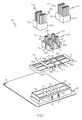
- FIG. 1 is an exploded isometric view of the multi-connector apparatus of the present invention, including a multi-bay connector header and an interlock plate;
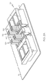
- FIG. 2A is an isometric view of an assembled multi-connector apparatus, with the interlock plate in a base position;
- FIG. 2B is a plan view of the multi-connector apparatus of FIG. 2A in the direction of the connector header bays;
- FIG. 3A is an isometric view of an assembled multi-connector apparatus, with the interlock plate in a shifted position
- FIG. 3B is a plan view of the multi-connector apparatus of FIG. 3A in the direction of the connector header bays.
- connection system 10 for a high voltage vehicle electrical system, including a multi-bay male-pin connector header 12 configured to receive multiple plug-in female connectors.
- the connector header 12 is mounted on a circuit board 13, but it should be understood that the connector header 12 may alternatively be integrated into a larger component such as the housing of a battery pack, if desired.
- the connection system 10 may be used in various other applications, both vehicular and non-vehicular.
- the illustrated connector header 12 includes a set of four high-voltage bays 14a, 14b, 14c, 14d configured to receive four high-voltage female power connectors 16a, 16b, 16c, 16d, and a set of four low-voltage bays 18a, 18b, 18c, 18d configured to receive four female signal connectors 20a, 20b, 20c, 20d.
- the connector pins in each of the high-voltage bays 14a, 14b, 14c, 14d are connected to the terminals of a high voltage battery pack (not shown), so that the power connectors 16a, 16b, 16c, 16d can couple high-voltage power to various high-voltage components (not shown) of the electrical system via the associated cables 22a, 22b, 22c, 22d.
- the connector pins in each of the low-voltage bays 18a, 18b, 18c, 18d are connected to temperature sensors or to voltage taps used to measure battery pack cell voltages, which are fed to a signal processor (not shown) by the signal connectors 20a, 20b, 20c, 20d and the associated cables 24a, 24b, 24c, 24d.
- An interlock plate 30 slidably fastened to connector header 12 requires a servicing technician to remove the signal connectors 20a-20d from low-voltage header bays 18a-18d prior to removing the power connectors 16a-16d from high-voltage header bays 14a-14d; and after servicing, to insert the power connectors 16a-16d into high-voltage header bays 14a-14d prior to inserting the signal connectors 20a-20d into low-voltage header bays 18a-18d.
- the purpose of the signal-before-power removal sequence is to allow the signal processor to detect the impending power disconnect and prepare the system for safe removal of the power connectors 16a-16d.
- the purpose of the power-before signal insertion sequence is to surge-protect the temperature sensors and the signal processor.
- Interlock plate 32 comprises a peripheral frame 31 that surrounds the connector header 12 and a top surface 32 that selectively and partially overlaps the bays 14a-14d and 18a-18d of connector header 12.
- the top surface 32 is provided with a set of four central openings 34a, 34b, 34c, 34d configured to receive the four power connectors 16a-16d, and a set of four laterally outboard openings 36a, 36b, 36c, 36d configured to receive the four signal connectors 20a-20d.
- a base position of the interlock plate 30 depicted in FIGS.
- the four central openings 34a-34d align with the four high-voltage bays 14a-14d of connector header 12, but the four laterally outboard openings 36a-36d are laterally offset with respect to the four low-voltage bays 18a-18d of connector header 12.
- the four power connectors 16a-16d can be freely inserted into (or removed from) the four high-voltage bays 14a-14d, but the four signal connectors 20a-20d cannot be inserted into the low-voltage bays 18a-18b.
- the sidewalls of power connectors 16a-16d are undercut laterally outboard of the cables 22a-22d as indicated by the reference numerals 38 so that once the power connectors 16a-16d are inserted into the four high-voltage bays 14a-14d, the interlock plate 30 can be slid laterally to the shifted position depicted in FIGS. 3A-3B .
- the four laterally outboard openings 36a-36d align with the four low-voltage bays 18a-18d to permit insertion (and removal) of the signal connectors 20a-20d, and portions of the interlock plate top surface 32 adjacent the openings 34a-34b overlap the marginal portions of the inserted power connectors 16a-16d to prevent them from being removed.
- connection system 10 includes a detent lock feature for retaining the interlock plate 30 in the base position prior to insertion of the power connectors 16a-16d.
- the detent lock feature is formed by a set of tabs 40 on interlock plate 30 and a corresponding set of slots 42 formed in the sidewalls of connector header 12.
- a domed projection is formed on the inboard face of each tab 40, and the domed projections seat in the connector header slots 42 when the interlock plate 30 is in the base position depicted in FIGS. 2A-2B .
- Each of the power connectors 16a-16d include a similar projection 44 formed on the sidewall adjacent to the sidewall of the connector header 12, so that when a given power connector is inserted into a high-voltage bay of connector header 12, the outwardly depending projection 44 on the side of the power connector engages the inwardly depending projection on the respective tab 40 of interlock plate 30, pushing the tab projection out of the respective slot 42.
- the interlock plate tabs 40 are no longer seated in the connector header slots 42, leaving the interlock plate 30 free for lateral movement with respect to the connector header 12.
- the detent lock feature serves to both initially retain the interlock plate 30 in the base position, and to prevent lateral movement of the interlock plate 30 with respect to the connector header 12 until the power connectors 16a-16d have all been inserted into the high-voltage bays 14a-14d of connector header 12.
- the multi-connector apparatus of the present invention provides a reliable way of ensuring a preordained connector make-and-break sequence any time the connectors 16a-16d and 20a-20d are inserted or removed, whether at initial factory installation or during subsequent maintenance or servicing.
- the detect lock feature holds the interlock plate 30 in the base position of FIGS. 2A-2B so that only the power connectors 16a-16d can be inserted into the connector header 12.
- all of the power connectors 16a-16d have to properly inserted before the detent lock feature releases the interlock plate 30.
- the installer slides the interlock plate 30 to the shifted position of FIGS. 3A-3B so that the signal connectors 20a-20d can be inserted into the connector header 12.
- the interlock plate 30 cannot be moved due to interference between it and the installed signal connectors 20a-20d.
- the signal connectors 20a-20d must be removed first due to the shifted position of the interlock plate 30. Then the technician can shift the interlock plate 30 to the base position of FIGS. 2A-2B , and remove the power connectors 16a-16d. And after at least one of the power connectors 16a-16d have been removed, the detent lock feature re-engages to retain the interlock plate 30 in the base position.
- the multi-connector apparatus of the present invention provides a cost-effective way ensuring a preordained connector make-and-break sequence because the interlock plate 30 is obviously inexpensive to produce, and the connectors 16a-16d and 20a-20d are either conventional or only slightly modified.
- the connector header 12 may be configured to accommodate a greater or lesser number of connectors, the connector header 12 may be molded as part of a larger component or assembly, and so forth. Accordingly, it is intended that the invention not be limited to the disclosed embodiment, but that it have the full scope permitted by the language of the following claims.
Applications Claiming Priority (1)
| Application Number | Priority Date | Filing Date | Title |
|---|---|---|---|
| US12/313,424 US7892011B2 (en) | 2008-11-20 | 2008-11-20 | Multi-connector apparatus with connection-sequencing interlock mechanism |
Publications (2)
| Publication Number | Publication Date |
|---|---|
| EP2190075A1 true EP2190075A1 (fr) | 2010-05-26 |
| EP2190075B1 EP2190075B1 (fr) | 2016-08-31 |
Family
ID=41666814
Family Applications (1)
| Application Number | Title | Priority Date | Filing Date |
|---|---|---|---|
| EP09175024.0A Active EP2190075B1 (fr) | 2008-11-20 | 2009-11-04 | Appareil multi-connecteur avec mécanisme d'inter-verrouillage à séquençage de connexion |
Country Status (2)
| Country | Link |
|---|---|
| US (1) | US7892011B2 (fr) |
| EP (1) | EP2190075B1 (fr) |
Cited By (3)
| Publication number | Priority date | Publication date | Assignee | Title |
|---|---|---|---|---|
| US8333613B2 (en) | 2011-02-15 | 2012-12-18 | Tyco Electronics Corporation | Header assembly |
| WO2016167866A1 (fr) * | 2015-04-13 | 2016-10-20 | Johnson Controls Technology Company | Corps de connecteur pour un module de batterie |
| CN107487183A (zh) * | 2016-07-18 | 2017-12-19 | 宝沃汽车(中国)有限公司 | 一种高压回路的通断控制方法、系统及电动汽车 |
Families Citing this family (7)
| Publication number | Priority date | Publication date | Assignee | Title |
|---|---|---|---|---|
| DE102008030339A1 (de) * | 2008-06-30 | 2009-12-31 | Continental Automotive Gmbh | Hochvolt-Steckverbindung für Kraftfahrzeuge |
| JP5827084B2 (ja) * | 2011-09-13 | 2015-12-02 | 矢崎総業株式会社 | 電気接続箱 |
| CN104078798A (zh) * | 2013-03-28 | 2014-10-01 | 鸿富锦精密电子(天津)有限公司 | 固线装置 |
| USD920251S1 (en) | 2015-09-10 | 2021-05-25 | Cps Technology Holdings Llc | Battery module connector barrel |
| USD867993S1 (en) | 2016-09-02 | 2019-11-26 | Cps Technology Holdings Llc | Battery module connector barrel |
| US10543795B2 (en) | 2016-09-02 | 2020-01-28 | Cps Technology Holdings Llc | Battery module connector barrel |
| US11973296B2 (en) | 2017-12-08 | 2024-04-30 | Smiths Interconnect Americas, Inc. | Highly configurable and modular high-speed connector system |
Citations (6)
| Publication number | Priority date | Publication date | Assignee | Title |
|---|---|---|---|---|
| US5017147A (en) | 1989-05-15 | 1991-05-21 | Yazaki Corporation | Connectors with cover providing connection sequence control |
| EP1378970A1 (fr) | 2002-07-02 | 2004-01-07 | Yazaki Corporation | Structure de connection de connecteurs |
| US7084361B1 (en) | 2005-09-22 | 2006-08-01 | General Motors Corporation | High voltage interlock switch |
| DE102006044655B3 (de) * | 2006-09-21 | 2008-02-21 | Tyco Electronics Amp Gmbh | Elektrische Steckverbinderanordnung mit festgelegter Steckreihenfolge |
| FR2908932A1 (fr) * | 2006-11-22 | 2008-05-23 | Renault Sas | Ensemble de raccordement electrique securise d'un accessoire de vehicule automobile. |
| US7402068B1 (en) | 2007-05-14 | 2008-07-22 | Gm Global Technology Operations, Inc. | High voltage interlock connection |
Family Cites Families (2)
| Publication number | Priority date | Publication date | Assignee | Title |
|---|---|---|---|---|
| US6607394B2 (en) | 2001-02-06 | 2003-08-19 | Optillion Ab | Hot-pluggable electronic component connection |
| JP4042536B2 (ja) * | 2002-11-08 | 2008-02-06 | 住友電装株式会社 | コネクタのロック構造 |
-
2008
- 2008-11-20 US US12/313,424 patent/US7892011B2/en active Active
-
2009
- 2009-11-04 EP EP09175024.0A patent/EP2190075B1/fr active Active
Patent Citations (6)
| Publication number | Priority date | Publication date | Assignee | Title |
|---|---|---|---|---|
| US5017147A (en) | 1989-05-15 | 1991-05-21 | Yazaki Corporation | Connectors with cover providing connection sequence control |
| EP1378970A1 (fr) | 2002-07-02 | 2004-01-07 | Yazaki Corporation | Structure de connection de connecteurs |
| US7084361B1 (en) | 2005-09-22 | 2006-08-01 | General Motors Corporation | High voltage interlock switch |
| DE102006044655B3 (de) * | 2006-09-21 | 2008-02-21 | Tyco Electronics Amp Gmbh | Elektrische Steckverbinderanordnung mit festgelegter Steckreihenfolge |
| FR2908932A1 (fr) * | 2006-11-22 | 2008-05-23 | Renault Sas | Ensemble de raccordement electrique securise d'un accessoire de vehicule automobile. |
| US7402068B1 (en) | 2007-05-14 | 2008-07-22 | Gm Global Technology Operations, Inc. | High voltage interlock connection |
Cited By (5)
| Publication number | Priority date | Publication date | Assignee | Title |
|---|---|---|---|---|
| US8333613B2 (en) | 2011-02-15 | 2012-12-18 | Tyco Electronics Corporation | Header assembly |
| WO2016167866A1 (fr) * | 2015-04-13 | 2016-10-20 | Johnson Controls Technology Company | Corps de connecteur pour un module de batterie |
| CN108112244A (zh) * | 2015-04-13 | 2018-06-01 | 江森自控科技公司 | 用于电池模块的连接筒 |
| CN107487183A (zh) * | 2016-07-18 | 2017-12-19 | 宝沃汽车(中国)有限公司 | 一种高压回路的通断控制方法、系统及电动汽车 |
| CN107487183B (zh) * | 2016-07-18 | 2020-08-28 | 宝沃汽车(中国)有限公司 | 一种高压回路的通断控制方法、系统及电动汽车 |
Also Published As
| Publication number | Publication date |
|---|---|
| US20100124836A1 (en) | 2010-05-20 |
| US7892011B2 (en) | 2011-02-22 |
| EP2190075B1 (fr) | 2016-08-31 |
Similar Documents
| Publication | Publication Date | Title |
|---|---|---|
| EP2190075B1 (fr) | Appareil multi-connecteur avec mécanisme d'inter-verrouillage à séquençage de connexion | |
| US5754406A (en) | Printed circuit board card guide having isolation arms and means for securing PCB | |
| EP3080873B1 (fr) | Connecteur de faisceau automobile à auto-réjection | |
| US9325114B2 (en) | Plug connector | |
| US5662496A (en) | Fuse junction box | |
| EP2056658B1 (fr) | Boîte de raccordement électrique à assembler sur un véhicule à moteur | |
| US8210864B1 (en) | Connector terminal position assurance device | |
| WO2019106467A1 (fr) | Connecteur électrique avec élément de maintien de position de borne | |
| US8608490B2 (en) | Modular wiring system | |
| EP3155695B1 (fr) | Soulagement de traction de câble | |
| EP3046185B1 (fr) | Connecteur | |
| EP0800237A1 (fr) | Structure modulaire pour l'interconnexion de différentes unités et les connecteurs respectifs | |
| US5997364A (en) | Electrical connector | |
| US5197896A (en) | Float mounting an electrical connector | |
| EP3331105B1 (fr) | Connecteur électrique pour un système de retenue de sécurité | |
| EP3038127B1 (fr) | Système d'obturateur claveté de panneau à usage sécurisé | |
| EP2700129B1 (fr) | Elément de connecteur ayant des seconds moyens de fixation de contact | |
| US9853391B2 (en) | Wire connector with integrated coaxial connection and front loaded terminal position assurance structures | |
| CA2935822C (fr) | Disjoncteur miniature destine a un centre d'alimentation sans toucher | |
| US6667887B2 (en) | Method and apparatus for locating and securing a component in a computer system | |
| US20030176107A1 (en) | Terminal position device apparatus, methods and articles of manufacture for securing sealed male connectors | |
| EP3604035B1 (fr) | Ensemble de connexion électrique, dispositif d'éclairage automobile et procédé de fabrication d'un dispositif d'éclairage automobile | |
| EP4362235A1 (fr) | Ensemble connecteur électrique |
Legal Events
| Date | Code | Title | Description |
|---|---|---|---|
| PUAI | Public reference made under article 153(3) epc to a published international application that has entered the european phase |
Free format text: ORIGINAL CODE: 0009012 |
|
| AK | Designated contracting states |
Kind code of ref document: A1 Designated state(s): AT BE BG CH CY CZ DE DK EE ES FI FR GB GR HR HU IE IS IT LI LT LU LV MC MK MT NL NO PL PT RO SE SI SK SM TR |
|
| AX | Request for extension of the european patent |
Extension state: AL BA RS |
|
| 17P | Request for examination filed |
Effective date: 20101126 |
|
| 17Q | First examination report despatched |
Effective date: 20110117 |
|
| REG | Reference to a national code |
Ref country code: DE Ref legal event code: R079 Ref document number: 602009040742 Country of ref document: DE Free format text: PREVIOUS MAIN CLASS: H01R0013640000 Ipc: H01R0013639000 |
|
| RIC1 | Information provided on ipc code assigned before grant |
Ipc: B60L 3/00 20060101ALI20160428BHEP Ipc: B60L 3/04 20060101ALI20160428BHEP Ipc: H01R 13/639 20060101AFI20160428BHEP Ipc: H01R 13/64 20060101ALI20160428BHEP |
|
| GRAP | Despatch of communication of intention to grant a patent |
Free format text: ORIGINAL CODE: EPIDOSNIGR1 |
|
| INTG | Intention to grant announced |
Effective date: 20160608 |
|
| GRAS | Grant fee paid |
Free format text: ORIGINAL CODE: EPIDOSNIGR3 |
|
| GRAA | (expected) grant |
Free format text: ORIGINAL CODE: 0009210 |
|
| AK | Designated contracting states |
Kind code of ref document: B1 Designated state(s): AT BE BG CH CY CZ DE DK EE ES FI FR GB GR HR HU IE IS IT LI LT LU LV MC MK MT NL NO PL PT RO SE SI SK SM TR |
|
| REG | Reference to a national code |
Ref country code: CH Ref legal event code: EP Ref country code: GB Ref legal event code: FG4D |
|
| REG | Reference to a national code |
Ref country code: IE Ref legal event code: FG4D |
|
| REG | Reference to a national code |
Ref country code: DE Ref legal event code: R096 Ref document number: 602009040742 Country of ref document: DE |
|
| REG | Reference to a national code |
Ref country code: AT Ref legal event code: REF Ref document number: 825703 Country of ref document: AT Kind code of ref document: T Effective date: 20161015 |
|
| REG | Reference to a national code |
Ref country code: FR Ref legal event code: PLFP Year of fee payment: 8 |
|
| REG | Reference to a national code |
Ref country code: LT Ref legal event code: MG4D |
|
| REG | Reference to a national code |
Ref country code: NL Ref legal event code: MP Effective date: 20160831 |
|
| REG | Reference to a national code |
Ref country code: AT Ref legal event code: MK05 Ref document number: 825703 Country of ref document: AT Kind code of ref document: T Effective date: 20160831 |
|
| PG25 | Lapsed in a contracting state [announced via postgrant information from national office to epo] |
Ref country code: HR Free format text: LAPSE BECAUSE OF FAILURE TO SUBMIT A TRANSLATION OF THE DESCRIPTION OR TO PAY THE FEE WITHIN THE PRESCRIBED TIME-LIMIT Effective date: 20160831 Ref country code: FI Free format text: LAPSE BECAUSE OF FAILURE TO SUBMIT A TRANSLATION OF THE DESCRIPTION OR TO PAY THE FEE WITHIN THE PRESCRIBED TIME-LIMIT Effective date: 20160831 Ref country code: NO Free format text: LAPSE BECAUSE OF FAILURE TO SUBMIT A TRANSLATION OF THE DESCRIPTION OR TO PAY THE FEE WITHIN THE PRESCRIBED TIME-LIMIT Effective date: 20161130 Ref country code: LT Free format text: LAPSE BECAUSE OF FAILURE TO SUBMIT A TRANSLATION OF THE DESCRIPTION OR TO PAY THE FEE WITHIN THE PRESCRIBED TIME-LIMIT Effective date: 20160831 |
|
| PG25 | Lapsed in a contracting state [announced via postgrant information from national office to epo] |
Ref country code: ES Free format text: LAPSE BECAUSE OF FAILURE TO SUBMIT A TRANSLATION OF THE DESCRIPTION OR TO PAY THE FEE WITHIN THE PRESCRIBED TIME-LIMIT Effective date: 20160831 Ref country code: AT Free format text: LAPSE BECAUSE OF FAILURE TO SUBMIT A TRANSLATION OF THE DESCRIPTION OR TO PAY THE FEE WITHIN THE PRESCRIBED TIME-LIMIT Effective date: 20160831 Ref country code: GR Free format text: LAPSE BECAUSE OF FAILURE TO SUBMIT A TRANSLATION OF THE DESCRIPTION OR TO PAY THE FEE WITHIN THE PRESCRIBED TIME-LIMIT Effective date: 20161201 Ref country code: SE Free format text: LAPSE BECAUSE OF FAILURE TO SUBMIT A TRANSLATION OF THE DESCRIPTION OR TO PAY THE FEE WITHIN THE PRESCRIBED TIME-LIMIT Effective date: 20160831 Ref country code: LV Free format text: LAPSE BECAUSE OF FAILURE TO SUBMIT A TRANSLATION OF THE DESCRIPTION OR TO PAY THE FEE WITHIN THE PRESCRIBED TIME-LIMIT Effective date: 20160831 Ref country code: BE Free format text: LAPSE BECAUSE OF NON-PAYMENT OF DUE FEES Effective date: 20161130 Ref country code: NL Free format text: LAPSE BECAUSE OF FAILURE TO SUBMIT A TRANSLATION OF THE DESCRIPTION OR TO PAY THE FEE WITHIN THE PRESCRIBED TIME-LIMIT Effective date: 20160831 |
|
| PG25 | Lapsed in a contracting state [announced via postgrant information from national office to epo] |
Ref country code: EE Free format text: LAPSE BECAUSE OF FAILURE TO SUBMIT A TRANSLATION OF THE DESCRIPTION OR TO PAY THE FEE WITHIN THE PRESCRIBED TIME-LIMIT Effective date: 20160831 Ref country code: RO Free format text: LAPSE BECAUSE OF FAILURE TO SUBMIT A TRANSLATION OF THE DESCRIPTION OR TO PAY THE FEE WITHIN THE PRESCRIBED TIME-LIMIT Effective date: 20160831 |
|
| PG25 | Lapsed in a contracting state [announced via postgrant information from national office to epo] |
Ref country code: CZ Free format text: LAPSE BECAUSE OF FAILURE TO SUBMIT A TRANSLATION OF THE DESCRIPTION OR TO PAY THE FEE WITHIN THE PRESCRIBED TIME-LIMIT Effective date: 20160831 Ref country code: DK Free format text: LAPSE BECAUSE OF FAILURE TO SUBMIT A TRANSLATION OF THE DESCRIPTION OR TO PAY THE FEE WITHIN THE PRESCRIBED TIME-LIMIT Effective date: 20160831 Ref country code: SM Free format text: LAPSE BECAUSE OF FAILURE TO SUBMIT A TRANSLATION OF THE DESCRIPTION OR TO PAY THE FEE WITHIN THE PRESCRIBED TIME-LIMIT Effective date: 20160831 Ref country code: PL Free format text: LAPSE BECAUSE OF FAILURE TO SUBMIT A TRANSLATION OF THE DESCRIPTION OR TO PAY THE FEE WITHIN THE PRESCRIBED TIME-LIMIT Effective date: 20160831 Ref country code: PT Free format text: LAPSE BECAUSE OF FAILURE TO SUBMIT A TRANSLATION OF THE DESCRIPTION OR TO PAY THE FEE WITHIN THE PRESCRIBED TIME-LIMIT Effective date: 20170102 Ref country code: BG Free format text: LAPSE BECAUSE OF FAILURE TO SUBMIT A TRANSLATION OF THE DESCRIPTION OR TO PAY THE FEE WITHIN THE PRESCRIBED TIME-LIMIT Effective date: 20161130 Ref country code: BE Free format text: LAPSE BECAUSE OF FAILURE TO SUBMIT A TRANSLATION OF THE DESCRIPTION OR TO PAY THE FEE WITHIN THE PRESCRIBED TIME-LIMIT Effective date: 20160831 Ref country code: SK Free format text: LAPSE BECAUSE OF FAILURE TO SUBMIT A TRANSLATION OF THE DESCRIPTION OR TO PAY THE FEE WITHIN THE PRESCRIBED TIME-LIMIT Effective date: 20160831 |
|
| REG | Reference to a national code |
Ref country code: DE Ref legal event code: R097 Ref document number: 602009040742 Country of ref document: DE |
|
| PG25 | Lapsed in a contracting state [announced via postgrant information from national office to epo] |
Ref country code: IT Free format text: LAPSE BECAUSE OF FAILURE TO SUBMIT A TRANSLATION OF THE DESCRIPTION OR TO PAY THE FEE WITHIN THE PRESCRIBED TIME-LIMIT Effective date: 20160831 |
|
| REG | Reference to a national code |
Ref country code: CH Ref legal event code: PL |
|
| PLBE | No opposition filed within time limit |
Free format text: ORIGINAL CODE: 0009261 |
|
| STAA | Information on the status of an ep patent application or granted ep patent |
Free format text: STATUS: NO OPPOSITION FILED WITHIN TIME LIMIT |
|
| PG25 | Lapsed in a contracting state [announced via postgrant information from national office to epo] |
Ref country code: LI Free format text: LAPSE BECAUSE OF NON-PAYMENT OF DUE FEES Effective date: 20161130 Ref country code: CH Free format text: LAPSE BECAUSE OF NON-PAYMENT OF DUE FEES Effective date: 20161130 |
|
| 26N | No opposition filed |
Effective date: 20170601 |
|
| REG | Reference to a national code |
Ref country code: IE Ref legal event code: MM4A |
|
| PG25 | Lapsed in a contracting state [announced via postgrant information from national office to epo] |
Ref country code: SI Free format text: LAPSE BECAUSE OF FAILURE TO SUBMIT A TRANSLATION OF THE DESCRIPTION OR TO PAY THE FEE WITHIN THE PRESCRIBED TIME-LIMIT Effective date: 20160831 |
|
| PG25 | Lapsed in a contracting state [announced via postgrant information from national office to epo] |
Ref country code: LU Free format text: LAPSE BECAUSE OF NON-PAYMENT OF DUE FEES Effective date: 20161130 |
|
| REG | Reference to a national code |
Ref country code: FR Ref legal event code: PLFP Year of fee payment: 9 |
|
| PG25 | Lapsed in a contracting state [announced via postgrant information from national office to epo] |
Ref country code: IE Free format text: LAPSE BECAUSE OF NON-PAYMENT OF DUE FEES Effective date: 20161104 |
|
| PG25 | Lapsed in a contracting state [announced via postgrant information from national office to epo] |
Ref country code: CY Free format text: LAPSE BECAUSE OF FAILURE TO SUBMIT A TRANSLATION OF THE DESCRIPTION OR TO PAY THE FEE WITHIN THE PRESCRIBED TIME-LIMIT Effective date: 20160831 Ref country code: HU Free format text: LAPSE BECAUSE OF FAILURE TO SUBMIT A TRANSLATION OF THE DESCRIPTION OR TO PAY THE FEE WITHIN THE PRESCRIBED TIME-LIMIT; INVALID AB INITIO Effective date: 20091104 |
|
| PG25 | Lapsed in a contracting state [announced via postgrant information from national office to epo] |
Ref country code: IS Free format text: LAPSE BECAUSE OF FAILURE TO SUBMIT A TRANSLATION OF THE DESCRIPTION OR TO PAY THE FEE WITHIN THE PRESCRIBED TIME-LIMIT Effective date: 20160831 Ref country code: MC Free format text: LAPSE BECAUSE OF FAILURE TO SUBMIT A TRANSLATION OF THE DESCRIPTION OR TO PAY THE FEE WITHIN THE PRESCRIBED TIME-LIMIT Effective date: 20160831 Ref country code: MK Free format text: LAPSE BECAUSE OF FAILURE TO SUBMIT A TRANSLATION OF THE DESCRIPTION OR TO PAY THE FEE WITHIN THE PRESCRIBED TIME-LIMIT Effective date: 20160831 Ref country code: TR Free format text: LAPSE BECAUSE OF FAILURE TO SUBMIT A TRANSLATION OF THE DESCRIPTION OR TO PAY THE FEE WITHIN THE PRESCRIBED TIME-LIMIT Effective date: 20160831 |
|
| PG25 | Lapsed in a contracting state [announced via postgrant information from national office to epo] |
Ref country code: MT Free format text: LAPSE BECAUSE OF NON-PAYMENT OF DUE FEES Effective date: 20161104 |
|
| REG | Reference to a national code |
Ref country code: DE Ref legal event code: R081 Ref document number: 602009040742 Country of ref document: DE Owner name: DELPHI TECHNOLOGIES IP LIMITED, BB Free format text: FORMER OWNER: DELPHI TECHNOLOGIES, INC., TROY, MICH., US |
|
| REG | Reference to a national code |
Ref country code: GB Ref legal event code: 732E Free format text: REGISTERED BETWEEN 20190214 AND 20190221 |
|
| P01 | Opt-out of the competence of the unified patent court (upc) registered |
Effective date: 20230327 |
|
| PGFP | Annual fee paid to national office [announced via postgrant information from national office to epo] |
Ref country code: GB Payment date: 20231013 Year of fee payment: 15 |
|
| PGFP | Annual fee paid to national office [announced via postgrant information from national office to epo] |
Ref country code: FR Payment date: 20231010 Year of fee payment: 15 Ref country code: DE Payment date: 20231010 Year of fee payment: 15 |