EP2189781A2 - Messanordnung zur spektroskopischen Untersuchung und Durchsatzerfassung eines Erntegutstroms - Google Patents
Messanordnung zur spektroskopischen Untersuchung und Durchsatzerfassung eines Erntegutstroms Download PDFInfo
- Publication number
- EP2189781A2 EP2189781A2 EP09173006A EP09173006A EP2189781A2 EP 2189781 A2 EP2189781 A2 EP 2189781A2 EP 09173006 A EP09173006 A EP 09173006A EP 09173006 A EP09173006 A EP 09173006A EP 2189781 A2 EP2189781 A2 EP 2189781A2
- Authority
- EP
- European Patent Office
- Prior art keywords
- spectrometer
- window
- measuring arrangement
- determination device
- throughput
- Prior art date
- Legal status (The legal status is an assumption and is not a legal conclusion. Google has not performed a legal analysis and makes no representation as to the accuracy of the status listed.)
- Ceased
Links
- 238000003306 harvesting Methods 0.000 claims abstract description 11
- 238000001514 detection method Methods 0.000 claims abstract description 10
- 230000007704 transition Effects 0.000 claims description 9
- 238000004140 cleaning Methods 0.000 claims description 7
- 230000001419 dependent effect Effects 0.000 claims description 4
- 238000011144 upstream manufacturing Methods 0.000 claims description 3
- 230000032258 transport Effects 0.000 claims 1
- 238000005259 measurement Methods 0.000 abstract description 2
- 238000010009 beating Methods 0.000 abstract 2
- 241001124569 Lycaenidae Species 0.000 description 6
- 238000011156 evaluation Methods 0.000 description 6
- 239000004615 ingredient Substances 0.000 description 6
- 238000001228 spectrum Methods 0.000 description 6
- 239000010902 straw Substances 0.000 description 4
- 230000002123 temporal effect Effects 0.000 description 3
- 238000009313 farming Methods 0.000 description 2
- 239000012535 impurity Substances 0.000 description 2
- 239000000463 material Substances 0.000 description 2
- 238000009825 accumulation Methods 0.000 description 1
- 238000001444 catalytic combustion detection Methods 0.000 description 1
- 239000000470 constituent Substances 0.000 description 1
- 238000010276 construction Methods 0.000 description 1
- 238000006073 displacement reaction Methods 0.000 description 1
- 239000003337 fertilizer Substances 0.000 description 1
- 239000004459 forage Substances 0.000 description 1
- 239000011521 glass Substances 0.000 description 1
- 238000011835 investigation Methods 0.000 description 1
- 239000002245 particle Substances 0.000 description 1
- 239000010908 plant waste Substances 0.000 description 1
- 102000004169 proteins and genes Human genes 0.000 description 1
- 108090000623 proteins and genes Proteins 0.000 description 1
- 229910052594 sapphire Inorganic materials 0.000 description 1
- 239000010980 sapphire Substances 0.000 description 1
Images


Classifications
-
- G—PHYSICS
- G01—MEASURING; TESTING
- G01N—INVESTIGATING OR ANALYSING MATERIALS BY DETERMINING THEIR CHEMICAL OR PHYSICAL PROPERTIES
- G01N21/00—Investigating or analysing materials by the use of optical means, i.e. using sub-millimetre waves, infrared, visible or ultraviolet light
- G01N21/84—Systems specially adapted for particular applications
- G01N21/85—Investigating moving fluids or granular solids
-
- A—HUMAN NECESSITIES
- A01—AGRICULTURE; FORESTRY; ANIMAL HUSBANDRY; HUNTING; TRAPPING; FISHING
- A01D—HARVESTING; MOWING
- A01D41/00—Combines, i.e. harvesters or mowers combined with threshing devices
- A01D41/12—Details of combines
- A01D41/127—Control or measuring arrangements specially adapted for combines
- A01D41/1271—Control or measuring arrangements specially adapted for combines for measuring crop flow
- A01D41/1272—Control or measuring arrangements specially adapted for combines for measuring crop flow for measuring grain flow
-
- A—HUMAN NECESSITIES
- A01—AGRICULTURE; FORESTRY; ANIMAL HUSBANDRY; HUNTING; TRAPPING; FISHING
- A01D—HARVESTING; MOWING
- A01D41/00—Combines, i.e. harvesters or mowers combined with threshing devices
- A01D41/12—Details of combines
- A01D41/127—Control or measuring arrangements specially adapted for combines
- A01D41/1277—Control or measuring arrangements specially adapted for combines for measuring grain quality
-
- G—PHYSICS
- G01—MEASURING; TESTING
- G01J—MEASUREMENT OF INTENSITY, VELOCITY, SPECTRAL CONTENT, POLARISATION, PHASE OR PULSE CHARACTERISTICS OF INFRARED, VISIBLE OR ULTRAVIOLET LIGHT; COLORIMETRY; RADIATION PYROMETRY
- G01J3/00—Spectrometry; Spectrophotometry; Monochromators; Measuring colours
- G01J3/02—Details
- G01J3/0291—Housings; Spectrometer accessories; Spatial arrangement of elements, e.g. folded path arrangements
-
- G—PHYSICS
- G01—MEASURING; TESTING
- G01J—MEASUREMENT OF INTENSITY, VELOCITY, SPECTRAL CONTENT, POLARISATION, PHASE OR PULSE CHARACTERISTICS OF INFRARED, VISIBLE OR ULTRAVIOLET LIGHT; COLORIMETRY; RADIATION PYROMETRY
- G01J3/00—Spectrometry; Spectrophotometry; Monochromators; Measuring colours
- G01J3/28—Investigating the spectrum
- G01J3/42—Absorption spectrometry; Double beam spectrometry; Flicker spectrometry; Reflection spectrometry
-
- G—PHYSICS
- G01—MEASURING; TESTING
- G01N—INVESTIGATING OR ANALYSING MATERIALS BY DETERMINING THEIR CHEMICAL OR PHYSICAL PROPERTIES
- G01N21/00—Investigating or analysing materials by the use of optical means, i.e. using sub-millimetre waves, infrared, visible or ultraviolet light
- G01N21/84—Systems specially adapted for particular applications
- G01N21/85—Investigating moving fluids or granular solids
- G01N2021/8592—Grain or other flowing solid samples
Definitions
- baffles which are arranged adjacent to the crop flow and dodge by the impact of crop flow against the force of a spring.
- the position of the baffle plate depends on the mass flow rate (ie the mass transported per unit of time in the crop stream) and is detected by means of a sensor, the signal of which is preferably recorded with local reference.
- Such baffles are usually arranged in combine harvester at the outlet of the grain from the cleaning upwardly conveying Körnerelevators within a transitional housing, from which they are spent by means of a screw conveyor in the grain tank (s. EP 0 208 025 A1 ).
- the EP 1 305 994 A1 suggests mounting a capacitive humidity sensor immediately below the baffle plate.
- the DE 199 22 867 A1 describes a spectroscopic measuring device for agricultural harvesters, which includes a light source to light the crop irradiate. Light reflected from the sample is deflected in a spectrometer by a dispersive element, such as a grating or a prism, in different wavelength-dependent directions. Detector elements receive the now known wavelengths associated light whose wavelengths are in the visible wavelength range or in the near infrared range. The output signals of the detector elements are fed to an evaluation device, which calculates certain parameters and constituent parts of the sample on the basis of the measured spectra. The measuring device is attached to the Erntegutstrom immediately adjacent to a discharge of the harvester, while the volume of the crop is detected by a sensor that detects the distance between pre-press rollers.
- a dispersive element such as a grating or a prism
- the US 5,751,421 A1 and the US 5 092 819 A1 Describe combine harvester with measuring device for spectroscopic investigation or detection of ingredients of the crop, which are arranged at the outlet of the grain elevator and interact there with the crop.
- the object underlying the invention is to provide an improved measuring arrangement for the spectroscopic examination and throughput detection of a crop stream, which enables in a simple manner an improved temporal correlation between the detection of the throughput measured values and the recording of the spectra of the same crop.
- the measuring arrangement comprises a spectrometer for determining the ingredients of the crop stream, which is equipped with a light source which illuminates the Erntegutstrom during the measuring operation through a window.
- the spectrometer comprises a dispersive element, for example a prism, a grating or a gap, which spectrally decomposes the light reflected from the crop stream and originating from the light source and again entering through the window, d. H. as a function of the respective wavelength in different directions.
- a detector having a plurality of photosensitive elements, such as photodiodes or CCDs, receives the dispersed light.
- the spectrometer supplies spectra of the sample which can be used in a suitable electronic evaluation device on the basis of calibration data for determining the ingredients of the crop stream.
- the measuring device comprises a throughput determination device, which preferably interacts mechanically with the crop to determine the respective (volume and / or mass) throughput per unit time.
- the throughput determination device and the spectrometer are connected to a recording device which records or stores the measured values of both the throughput determination device and the spectrometer during operation.
- the throughput determination device and the spectrometer are arranged in close spatial proximity to one another.
- the measured values of the throughput determination device and of the spectrometer can be assigned to the same crop with sufficient accuracy.
- the temporal correlation of both measured values is therefore significantly improved.
- the readings may be recorded for billing purposes, for example, to determine the commercial value of the crop based on the amount and content of certain ingredients, such as proteins, or for precision farming purposes, specifically to follow up subsequent fertilizer location based on the yield and ingredients of the crop to be able to.
- the measured values can be used for the automatic adjustment of components of the harvesting machine, since, for example, based on the spectra of the Spectrometer can be detected any impurities, which in turn can be used to improve the setting of the cleaning of a combine harvester.
- the throughput determination device comprises a movably mounted, prestressed baffle plate, against which the crop stream bounces.
- the deflection of the baffle plate against the bias usually provided by a spring depends on the mass flow rate and is detected by means of a position sensor.
- the throughput determination device could also optically detect the volume of the crop (instead of mechanically), cf. the DE 10 2008 017 671 A1 and the references cited there.
- the spectrometer may be disposed immediately upstream or downstream of the flow rate determining means with respect to the flow direction of the crop stream, or its window may be disposed within an aperture of the impact plate of the flow rate detecting means. In the latter case, the entire spectrometer can move together with the baffle plate when the latter is deflected by the crop, or the actual spectrometer, with the exception of the window, is stationary, while only moving the window with the baffle plate.
- the actual spectrometer except the window, d. H. the light source, the dispersive element and the detector may also be located within a common housing with the position sensor of the flow rate detection device.
- the measuring arrangement according to the invention can be used on any harvesters, such as self-propelled, mounted or drawn balers, forage harvesters or combine harvesters.
- a preferred mounting location is for combine harvesters at the outlet of a clean grain elevator elevator within a transition housing.
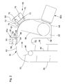
- FIG. 1 shows a self-propelled agricultural harvester 10 in the form of a combine with a frame 12, on both sides of which are in engagement with the ground front wheels 14, which serve to propel the harvester 10 in a forward direction, in the FIG. 1 extends to the right, and rear, steerable wheels 16 are mounted.
- the operation of the harvester 10 is controlled by the operator's cab 18.
- a cutter 20 is used to harvest grain-containing crop and feed it to a feeder 22.
- the harvested crop is fed by the feeder 22 to a beater 24 which feeds the crop to an axial crop processor 26.
- directions, such as front and rear refer to the forward direction of the harvester 10.
- the Erntegutbearbeitungs worn 26 includes a rotor housing and a rotor disposed therein, are attached to the Gutbearbeitungsiata.
- an axial Erntegutbearbeitungsaku 26 can also be a tangential threshing drum and a subsequent axial separator or straw shaker can be used.
- Grain and chaff, the through a concave and a separating grate are fed to a cleaning system 28 with a fan and displaceable in a swinging motion slats.
- the cleaning system 28 removes the chaff and feeds the clean grain via a screw conveyor 30 to a clean grain elevator 32 which conveys the clean grain into a transition casing 34 from which it is conveyed into a grain tank 38 by means of another screw conveyor 36.
- the clean grain in the grain tank 38 may be unloaded by a discharge auger 40 onto a grain cart, trailer or truck.
- Broken straw leaving the crop processor 26 is ejected through an outlet from the crop processor 26 and fed to an ejector drum 42 which ejects the straw to the rear or feeds it to a straw chopper (not shown).
- the FIG. 2 shows the transition housing 34 in an enlarged view.
- the elevator 32 is designed as a paddle conveyor and comprises one or more chains 44, which rotate around an upper deflecting wheel 46 and a lower deflecting wheel 48, one of which is driven.
- the chain 44 carries a plurality of paddle-shaped paddles 50, which deliver the upwardly conveyed grain above the upper guide wheel 46 approximately horizontally.
- the transition housing 34 comprises a trough 52, in which the inlet of the further screw conveyor 36 is located, and which is bounded by a wall 54 down and to the elevator 32 out.
- the lateral portion of the wall 54 is connected by a roof-shaped portion 62 to a rear wall 56 of a housing of the elevator 32, which is trapped forward by a front wall 58.
- the front wall 58 is curved on its upper side in a cover 60 of the transition housing 34 via.
- the transition housing 34 is bounded by a concave curved baffle plate 64 of a flow rate determination device 66 up and forward, against which the discarded by the elevator 32 grain bounces.
- the flow rate determination device 66 further comprises a housing 68 positioned on the outside of the baffle plate 64 and the transition housing 34, which is rigidly connected to the frame 12.
- a plate 70 is slidably supported by guides 72 in an obliquely upward and forward direction.
- the plate 70 is rigidly connected to the baffle 64 by a tube 74 and can move with the baffle 64 and the tube 74 opposite the housing 68.
- a spring 76 biases the plate 70 downwardly and rearwardly so that the plate 70 moves up and forward against the force of the spring 76 by the grain impinging on the baffle plate 64 becomes.
- a position sensor 78 in the form of a potentiometer detects the position of the plate 70 and thus of the baffle plate 64, so that its output signal is a measure of the mass flow rate of the crop stream discharged by the elevator 32.
- the spectrometer 80a comprises a housing 82 with an opening in which a window 84 is arranged, the disk of which preferably consists of sapphire glass or another sufficiently wear-resistant material which is sufficiently transparent in the wavelength range to be examined.
- a light source 86 which irradiates the output from the elevator 32 Erntegutstrom through the window 84 with broadband, so-called white light, which usually covers the near infrared range.
- Light reflected from the crop stream re-enters the housing 82 through the window 84, where it is directed by a lens system 88 onto a dispersive element 90 in the form of a concave mirror with a grating structure attached to its underside which directs the light in wavelength dependent directions deflects and finally reaches a detector 92 with a series of photosensitive elements which emit signals dependent on the intensity of the received light.
- An evaluation device 94 connected to the detector 92 evaluates the output signals of the detector 92 and supplies spectra and / or information derived therefrom, e.g. B. levels of ingredients in the crop stream.
- Suitable spectrometers are used in the DE 199 22 867 A1 and in the DE 10 2004 048 103 A1 whose disclosures are incorporated by reference into the present documentation.
- the spectrometer 80a is located above the cover 60 of the transition housing 34 with the window 84 within an opening in a ramp 96 located immediately upstream of the baffle 64.
- the ramp 96 serves to direct the crop stream discharged by the elevator 32 onto the baffle plate 64 and, in particular, to prevent grain from undesirably reaching the outside thereof at the front edge of the baffle plate 64 with respect to the crop stream. Thanks to an adjustment of the ramp 96 and the window 84 by a relatively small angle, which may for example be between 3 and 5 °, a self-cleaning function of the glazing or pane of the window 84 of the spectrometer 80a is achieved by the mass flow of the crop. Pollution or
- the spectrometer 80b is located at the downstream end of the baffle plate 64, with the window 84 extending obliquely downwardly and rearwardly toward the center of the well 52.
- the windows 84 of both spectrometers 80a, 80b are surrounded by the flow of crop material, so that any impurities are entrained and do not adhere to the windows 84.
- the evaluation device 94 of the spectrometer 80a or 80b and the position sensor 78 of the throughput determination device 66 are connected via a bus system or an associated cable or via radio or optically to a recording device 98 which is located in the operator cab 18, cf. FIG. 1 ,
- the recording device 98 is further provided with a position determining device 100 in the form of an antenna and receiving devices for receiving and processing signals of a satellite-based position determining system, for. GPS or Glonass or Eureka.
- the signals of the evaluation device 94 of the spectrometer 80a or 80b and of the position sensor 78 of the throughput determination device 66 are thus georeferenced recorded by the recording device 98 for later use for billing purposes or for use in precision agriculture.
- these signals may be used to automatically adjust components of the harvester 10, for example to adjust the fan speed and sieve opening width of the cleaning system 28 or the speed of the axial crop processor 26.
- Attach the spectrometer (s) 80a and / or 80b and The throughput determination device 66 in the immediate vicinity has the advantage that in each case measured values of the same crop are detected, ie that the temporal correlation of the measured values is very good.
- FIG. 3 With reference to Figure 1, a further mounting option for a spectrometer 80c is shown.
- the housing 82 of the spectrometer 80c is here rigidly connected to the frame 12 of the harvester 10, while the window 84 is rigidly embedded in the upper, still approximately horizontally extending region of the baffle plate 64.
- the nozzle 102 may also be partially or completely flexible, z. B. as a bellows, be executed and rigidly connected to the edge of the window 84.
- the in the FIG. 4 The measuring arrangement shown essentially corresponds to the embodiment according to FIG. 3
- the housing 82 of the spectrometer 80d is connected via the nozzle 102 rigidly connected to the edge of the window 84 and thus moves with the baffle plate 64 with.
- the housing 82 of the spectrometer 80d is further supported by bearings 104 on the frame 12 of the harvester 10, which allow the housing 82 to follow the movement of the baffle plate 64 by a vertical movement of the housing 82 by ball bearings and a pivoting movement of the housing Enable prism bearings.
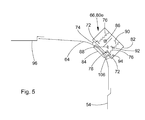
- FIG. 5 shows a fifth embodiment are shown, in which the previous embodiments corresponding elements have been given the same reference numerals.
- the essential difference from the preceding embodiments lies in the fact that the light source, the dispersive element and the detector of the spectrometer 80e on the one hand and the position sensor 72 and the spring 76 of the flow rate determination device 66 on the other hand are arranged within a common housing 82 which is fixed to the frame 12 of FIG Harvesting machine 10 is attached.
- the window 84 is located in the region below the maximum curvature of the baffle plate 64 and is fixedly mounted to the baffle plate 64 in a corresponding section thereof.
- the baffle plate 64 is connected by a tube 74 with a ring 106 which is biased by springs 76 in the direction of the Erntegutstrom and slidably mounted in guides 72.
- the position of the ring 106 in its displacement direction is detected by means of the position sensor 72, analogous to the embodiment according to FIG FIG. 2 .
- the light source 86, the lens system 88, the dispersive element 90 and the detector 92 of the spectrometer 80e as well as its evaluation device 94 find place.
- the modes of action of the measuring arrangements according to FIGS. 3 to 5 correspond to those of the measuring arrangement according to FIG. 1 and 2 ,
Landscapes
- Physics & Mathematics (AREA)
- Spectroscopy & Molecular Physics (AREA)
- General Physics & Mathematics (AREA)
- Life Sciences & Earth Sciences (AREA)
- Environmental Sciences (AREA)
- Biochemistry (AREA)
- Analytical Chemistry (AREA)
- General Health & Medical Sciences (AREA)
- Chemical & Material Sciences (AREA)
- Immunology (AREA)
- Pathology (AREA)
- Health & Medical Sciences (AREA)
- Investigating Or Analysing Materials By Optical Means (AREA)
Abstract
Description
- Die Erfindung betrifft eine Messanordnung zur spektroskopischen Untersuchung und Durchsatzerfassung eines Erntegutstroms, mit:
- einem Spektrometer, das eine Lichtquelle, ein Fenster, ein dispersives Element und einen Detektor umfasst, wobei die Lichtquelle im Betrieb den Erntegutstrom durch das Fenster beleuchtet und vom Erntegutstrom reflektiertes Licht durch das Fenster auf das dispersive Element fällt, das es wellenlängenabhängig in unterschiedliche Richtungen auf den Detektor ablenkt,
- einer mit dem Erntegutstrom zusammenwirkenden Durchsatzermittlungseinrichtung, und
- einer Aufzeichnungseinrichtung zur Aufzeichnung der Messwerte des Spektrometers und der Durchsatzermittlungseinrichtung.
- Bei landwirtschaftlichen Erntemaschinen besteht ein Bedürfnis, den Durchsatz von einem Feld aufgenommenen Ernteguts zu erfassen, um ihn beispielsweise zu Abrechnungszwecken oder für Anwendungen in der Präzisionslandwirtschaft zu dokumentieren. Der Durchsatz wird üblicherweise durch Prallplatten gemessen, die dem Erntegutstrom benachbart angeordnet sind und durch den aufprallenden Erntegutstrom gegen die Kraft einer Feder ausweichen. Die Position der Prallplatte hängt vom Massendurchsatz (d. h. der pro Zeiteinheit im Erntegutstrom transportierten Masse) ab und wird mittels eines Sensors erfasst, dessen Signal vorzugsweise ortsreferenziert aufgezeichnet wird. Derartige Prallplatten sind bei Mähdreschern üblicherweise am Auslass des das Korn von der Reinigung nach oben abfördernden Körnerelevators innerhalb eines Übergangsgehäuses angeordnet, aus dem sie mittels eines Schneckenförderers in den Korntank verbracht werden (s.
EP 0 208 025 A1 ). DieEP 1 305 994 A1 schlägt vor, unmittelbar unterhalb der Prallplatte einen kapazitiven Feuchtigkeitssensor anzubringen. - Außerdem sind im Stand der Technik verschiedene spektroskopische Messeinrichtungen beschrieben worden, die in der Landwirtschaft unter Anderem Verwendung finden, um Erntegut zu klassifizieren. Die
DE 199 22 867 A1 beschreibt eine spektroskopische Messeinrichtung für landwirtschaftliche Erntemaschinen, die eine Lichtquelle umfasst, um das Erntegut mit Licht zu bestrahlen. Von der Probe reflektiertes Licht wird in einem Spektrometer durch ein dispersives Element, beispielsweise ein Gitter oder ein Prisma, in unterschiedliche, von der Wellenlänge abhängige Richtungen abgelenkt. Detektorelemente empfangen das nunmehr bekannten Wellenlängen zugeordnete Licht, dessen Wellenlängen im sichtbaren Wellenlängenbereich oder im nahen Infrarotbereich liegen. Die Ausgangssignale der Detektorelemente werden einer Auswertungseinrichtung zugeführt, die anhand der gemessenen Spektren bestimmte Parameter und Inhaltsstoffanteile der Probe ausrechnet. Die Messeinrichtung ist dem Erntegutstrom unmittelbar benachbart an einer Austrageinrichtung der Erntemaschine angebracht, während das Volumen des Ernteguts durch einen Sensor erfasst wird, der den Abstand zwischen Vorpresswalzen erfasst. - Auch die
US 5 751 421 A1 und dieUS 5 092 819 A1 beschreiben Mähdrescher mit Messeinrichtung zur spektroskopischen Untersuchung bzw. Erfassung von Inhaltsstoffen des Ernteguts, die am Auslass des Körnerelevators angeordnet sind und dort mit dem Erntegut zusammenwirken. - Während bei den Messeinrichtungen nach
US 5 751 421 A1 undUS 5 092 819 A1 keine kontinuierliche Erfassung des Erntegutdurchsatzes vorgesehen ist und die in derEP 0 208 025 A1 undEP 1 305 994 A1 beschriebenen Messanordnungen keine spektroskopische Untersuchung des Ernteguts erlauben, leidet die Messanordnung gemäßDE 199 22 867 A1 unter dem Nachteil, dass ein Zeitversatz zwischen der Erfassung des Durchsatzes an den Vorpresswalzen und der spektroskopischen Untersuchung desselben Ernteguts vorliegt. Die Zuordnung der Spektren zu den Durchsatzmesswerten ist demnach problematisch und würde neben hohem Rechenaufwand eine präzise Erfassung der aktuellen Fördergeschwindigkeit durch die Erntemaschine erfordern. - Die der Erfindung zu Grunde liegende Aufgabe wird darin gesehen, eine gegenüber dem Stand der Technik verbesserte Messanordnung zur spektroskopischen Untersuchung und Durchsatzerfassung eines Erntegutstroms bereitzustellen, die auf einfache Weise eine verbesserte zeitliche Korrelation zwischen der Erfassung der Durchsatzmesswerte und der Aufnahme der Spektren desselben Ernteguts ermöglicht.
- Diese Aufgabe wird erfindungsgemäß durch die Lehre des Patentanspruchs 1 gelöst, wobei in den weiteren Patentansprüchen Merkmale aufgeführt sind, die die Lösung in vorteilhafter Weise weiterentwickeln.
- Die Messanordnung umfasst ein Spektrometer zur Bestimmung der Inhaltsstoffe des Erntegutstroms, das mit einer Lichtquelle ausgestattet ist, die den Erntegutstrom während des Messbetriebs durch ein Fenster beleuchtet. Außerdem umfasst das Spektrometer ein dispersives Element, beispielsweise ein Prisma, ein Gitter oder einen Spalt, der vom Erntegutstrom reflektiertes, von der Lichtquelle stammendes und wieder durch das Fenster einlaufendes Licht spektral zerlegt, d. h. in Abhängigkeit von der jeweiligen Wellenlänge in unterschiedliche Richtungen ablenkt. Ein Detektor mit einer Vielzahl lichtempfindlicher Elemente, beispielsweise Photodioden oder CCDs, empfängt das dispergierte Licht. Da die Position des jeweiligen Elements des Detektors einer Wellenlänge zugeordnet werden kann, liefert das Spektrometer Spektren der Probe, die in einer geeigneten elektronischen Auswertungseinrichtung anhand von Kalibrierdaten zur Bestimmung der Inhaltsstoffe des Erntegutstroms dienen können. Außerdem umfasst die Messeinrichtung eine Durchsatzermittlungseinrichtung, die vorzugsweise mechanisch mit dem Erntegut zusammenwirkt, um den jeweiligen (Volumen- und/oder Massen-) Durchsatz pro Zeiteinheit zu bestimmen. Die Durchsatzermittlungseinrichtung und das Spektrometer sind mit einer Aufzeichnungseinrichtung verbunden, die während des Betriebs die Messwerte sowohl der Durchsatzermittlungseinrichtung als auch des Spektrometers aufzeichnet oder abspeichert. Die Durchsatzermittlungseinrichtung und das Spektrometer sind in unmittelbarer räumlicher Nähe zueinander angeordnet.
- Auf diese Weise können die Messwerte der Durchsatzermittlungseinrichtung und des Spektrometers mit hinreichender Genauigkeit demselben Erntegut zugeordnet werden. Die zeitliche Korrelation beider Messwerte ist demnach wesentlich verbessert. Die Messwerte können für Abrechnungszwecke, beispielsweise zur Ermittlung des kommerziellen Werts des Ernteguts anhand der Menge und des Gehalts an bestimmten Inhaltsstoffen, wie Proteinen, oder zu Zwecken der Präzisionslandwirtschaft aufgezeichnet werden, insbesondere um die nachfolgende Düngung anhand des Ertrags und der Inhaltsstoffe des Ernteguts ortsspezifisch durchführen zu können. Außerdem können die Messwerte zur selbsttätigen Einstellung von Komponenten der Erntemaschine dienen, da beispielsweise anhand der Spektren des Spektrometers eventuelle Verunreinigungen erkannt werden können, was wiederum zur Verbesserung der Einstellung der Reinigung eines Mähdreschers genutzt werden kann.
- Bei einer Ausführungsform der Erfindung umfasst die Durchsatzermittlungseinrichtung eine beweglich gelagerte, vorgespannte Prallplatte, gegen die der Erntegutstrom prallt. Die Auslenkung der Prallplatte gegen die in der Regel mittels einer Feder bereitgestellte Vorspannung hängt vom Massendurchsatz ab und wird mittels eines Positionssensors erfasst. Es wäre aber auch denkbar, mittels der Durchsatzermittlungseinrichtung den Volumendurchsatz zu erfassen, beispielsweise mittels einer quer zur Flussrichtung beweglichen Platte oder Walze, die gegen den Erntegutstrom vorgespannt ist und durch ihn bewegt wird, während das Spektrometer durch ein Fenster in der Platte mit dem Erntegut zusammenwirkt oder innerhalb der Walze angeordnet ist und durch ein ringförmiges Fenster in der Walze mit dem Erntegut zusammenwirkt. Die Durchsatzermittlungseinrichtung könnte das Volumen des Ernteguts (anstelle mechanisch) auch optisch erfassen, vgl. die
DE 10 2008 017 671 A1 und die dort zitierten Referenzen. - Das Spektrometer kann bezüglich der Flussrichtung des Erntegutstroms unmittelbar stromauf oder stromab der Durchsatzermittlungseinrichtung angeordnet werden, oder sein Fenster wird innerhalb einer Öffnung der Prallplatte der Durchsatzermittlungseinrichtung angeordnet. Im letztgenannten Fall kann sich das gesamte Spektrometer gemeinsam mit der Prallplatte bewegen, wenn letztere durch das Erntegut ausgelenkt wird, oder das eigentliche Spektrometer, mit Ausnahme des Fensters, ist ortsfest, während sich nur das Fenster mit der Prallplatte bewegt. Das eigentliche Spektrometer mit Ausnahme des Fensters, d. h. die Lichtquelle, das dispersive Element und der Detektor, können sich auch mit dem Positionssensor der Durchsatzermittlungseinrichtung innerhalb eines gemeinsamen Gehäuses befinden.
- Die erfindungsgemäße Messanordnung kann an beliebigen Erntemaschinen, wie selbstfahrenden, angebauten oder gezogenen Ballenpressen, Feldhäckslern oder Mähdreschern verwendet werden. Eine bevorzugte Anbringungsposition befindet sich bei Mähdreschern am Auslass eines Elevators für sauberes Korn innerhalb eines Übergangsgehäuses.
- In den Zeichnungen sind fünf nachfolgend näher beschriebene Ausführungsbeispiele der Erfindung dargestellt. Es zeigt:
- Fig. 1
- eine schematische seitliche Ansicht einer Erntemaschine mit einer erfindungsgemäßen Messanordnung zur spektroskopischen Untersuchung und zur Ermittlung des Durchsatzes eines Erntegutstroms, wobei zwei Ausführungsformen hinsichtlich der Anbringung des Spektrometers vorgesehen sind,
- Fig. 2
- eine vergrößerte seitliche Ansicht des Auslassbereichs des Körnerelevators der Erntemaschine aus
Figur 1 , - Fig. 3
- eine vergrößerte seitliche Ansicht des Auslassbereichs des Körnerelevators der Erntemaschine aus
Figur 1 mit einer dritten Ausführungsform einer erfindungsgemäßen Messanordnung, und - Fig. 4
- eine vergrößerte seitliche Ansicht des Auslassbereichs des Körnerelevators der Erntemaschine aus
Figur 1 mit einer vierten Ausführungsform einer erfindungsgemäßen Messanordnung, und - Fig. 5
- eine vergrößerte seitliche Ansicht des Auslassbereichs des Körnerelevators der Erntemaschine aus
Figur 1 mit einer fünften Ausführungsform einer erfindungsgemäßen Messanordnung. - Die
Figur 1 zeigt eine selbstfahrende landwirtschaftliche Erntemaschine 10 in Form eines Mähdreschers mit einem Rahmen 12, an dessen beiden Seiten im Eingriff mit dem Boden befindliche vordere Räder 14, die zum Vortrieb der Erntemaschine 10 in einer Vorwärtsrichtung dienen, die in derFigur 1 nach rechts verläuft, sowie rückwärtige, lenkbare Räder 16 angebracht sind. Der Betrieb der Erntemaschine 10 wird von der Bedienerkabine 18 aus kontrolliert. Im Erntebetrieb wird ein Schneidwerk 20 verwendet, um Korn enthaltendes Erntegut zu ernten und es einem Schrägförderer 22 zuzuführen. Das geerntete Gut wird durch den Schrägförderer 22 einer Leittrommel 24 zugeführt, welche das Erntegut einer axialen Erntegutbearbeitungseinrichtung 26 zuführt. Im Folgenden beziehen sich Richtungsangaben, wie vorn und hinten, auf die Vorwärtsrichtung der Erntemaschine 10. - Die Erntegutbearbeitungseinrichtung 26 umfasst ein Rotorgehäuse und einen darin angeordneten Rotor, an dem Gutbearbeitungselemente befestigt sind. Anstelle einer axialen Erntegutbearbeitungseinheit 26 kann auch eine tangentiale Dreschtrommel und eine ihr folgende axiale Trenneinrichtung oder Strohschüttler verwendet werden. Korn und Spreu, die durch einen Dreschkorb und ein Trennrost fallen, werden einem Reinigungssystem 28 mit einem Gebläse und in eine Schwingbewegung versetzbaren Lamellensieben zugeführt. Das Reinigungssystem 28 entfernt die Spreu und führt das saubere Korn über einen Schneckenförderer 30 einem Elevator 32 für sauberes Korn zu, welcher das saubere Korn in ein Übergangsgehäuse 34 fördert, aus dem es mittels eines weiteren Schneckenförderers 36 in einen Korntank 38 gefördert wird. Das saubere Korn im Korntank 38 kann durch einen Entladeschneckenförderer 40 auf einen Kornwagen, Anhänger oder Lastwagen entladen werden. Ausgedroschenes, die Erntegutbearbeitungseinrichtung 26 verlassendes Stroh wird durch einen Auslass aus der Erntegutbearbeitungseinrichtung 26 ausgestoßen und einer Auswurftrommel 42 zugeführt, die das Stroh nach hinten auswirft oder einem Strohhäcksler (nicht gezeigt) zuführt.
- Die
Figur 2 zeigt das Übergangsgehäuse 34 in einer vergrößerten Darstellung. Der Elevator 32 ist als Paddelförderer ausgebildet und umfasst eine oder mehrere Ketten 44, die um ein oberes Umlenkrad 46 und ein unteres Umlenkrad 48 umlaufen, von denen eines angetrieben ist. Die Kette 44 trägt mehrere schaufelförmige Paddel 50, die das nach oben heran geförderte Korn oberhalb des oberen Umlenkrads 46 näherungsweise horizontal abgeben. Das Übergangsgehäuse 34 umfasst eine Wanne 52, in der sich der Einlass des weiteren Schneckenförderers 36 befindet, und die durch eine Wand 54 nach unten und zum Elevator 32 hin begrenzt wird. Der seitliche Teil der Wand 54 ist durch einen dachförmigen Abschnitt 62 mit einer rückwärtigen Wand 56 eines Gehäuses des Elevators 32 verbunden, der nach vorn durch eine vordere Wand 58 eingeschlossen wird. Die vordere Wand 58 geht an ihrer Oberseite kurvenförmig in einen Deckel 60 des Übergangsgehäuses 34 über. An der dem Auslass des Elevators 32 gegenüber liegenden Seite wird das Übergangsgehäuse 34 durch eine konkav gekrümmte Prallplatte 64 einer Durchsatzermittlungseinrichtung 66 nach oben und vorn begrenzt, gegen die das vom Elevator 32 abgeworfene Korn prallt. - Die Durchsatzermittlungseinrichtung 66 umfasst weiterhin ein an der Außenseite der Prallplatte 64 und des Übergangsgehäuses 34 positioniertes Gehäuse 68, das starr mit dem Rahmen 12 verbunden ist. In dem Gehäuse 68 ist eine Platte 70 durch Führungen 72 in einer schräg nach oben und vorn verlaufenden Richtung verschiebbar gelagert. Die Platte 70 ist durch ein Rohr 74 starr mit der Prallplatte 64 verbunden und kann sich mit der Prallplatte 64 und dem Rohr 74 gegenüber dem Gehäuse 68 bewegen. Eine Feder 76 spannt die Platte 70 nach unten und hinten vor, so dass die Platte 70 durch auf die Prallplatte 64 auftreffendes Korn gegen die Kraft der Feder 76 nach oben und vorn bewegt wird. Ein Positionssensor 78 in Form eines Potentiometers erfasst die Position der Platte 70 und demnach der Prallplatte 64, so dass sein Ausgangssignal ein Maß für den Massendurchsatz des vom Elevator 32 abgegebenen Erntegutstroms ist.
- Weiterhin sind in den
Figuren 1 und2 an zwei unterschiedlichen Positionen Spektrometer 80a, 80b eingezeichnet. In der Regel wird nur eines der Spektrometer 80a oder 80b eingebaut. Die beiden eingezeichneten Spektrometer 80a, 80b dienen zur Veranschaulichung der beiden Positionierungsmöglichkeiten. Die Spektrometer 80a, 80b sind identischen Aufbaus, der im Folgenden anhand des Spektrometers 80a diskutiert wird. Das Spektrometer 80a umfasst ein Gehäuse 82 mit einer Öffnung, in der ein Fenster 84 angeordnet ist, dessen Scheibe vorzugsweise aus Saphirglas oder einem anderen, hinreichend verschleißresistenten und im zu untersuchenden Wellenlängenbereich ausreichend transparentem Material besteht. Innerhalb des Gehäuses 82 befindet sich eine Lichtquelle 86, die den vom Elevator 32 abgegebenen Erntegutstrom durch das Fenster 84 mit breitbandigem, so genannten weißem Licht bestrahlt, das in der Regel den Nahinfrarotbereich abdeckt. Vom Erntegutstrom reflektiertes Licht tritt durch das Fenster 84 wieder in das Gehäuse 82 ein, wird dort durch ein Linsensystem 88 auf ein dispersives Element 90 in Form eines konkaven Spiegels mit einer an seiner Unterseite angebrachten Gitterstruktur geleitet, die das Licht in von der Wellenlänge abhängige Richtungen ablenkt und erreicht schließlich einen Detektor 92 mit einer Reihe lichtempfindlicher Elemente, die von der Intensität des empfangenen Lichts abhängige Signale abgeben. Eine mit dem Detektor 92 verbundene Auswertungseinrichtung 94 wertet die Ausgangssignale des Detektors 92 aus und liefert Spektren und/oder daraus abgeleitete Informationen, z. B. Anteile an Inhaltsstoffen im Erntegutstrom. Geeignete Spektrometer werden in derDE 199 22 867 A1 und in derDE 10 2004 048 103 A1 beschrieben, deren Offenbarungen durch Verweis mit in die vorliegenden Unterlagen aufgenommen werden. - Das Spektrometer 80a ist oberhalb des Deckels 60 des Übergangsgehäuses 34 angeordnet, wobei sich das Fenster 84 innerhalb einer Öffnung in einer Rampe 96 befindet, die unmittelbar stromauf der Prallplatte 64 angeordnet ist. Die Rampe 96 dient dazu, den vom Elevator 32 abgegebenen Erntegutstrom auf die Prallplatte 64 zu lenken und insbesondere zu verhindern, dass Korn an der bezüglich des Erntegutstroms vorderen Kante der Prallplatte 64 in unerwünschter Weise an deren Außenseite gelangt. Dank einer Anstellung der Rampe 96 und des Fensters 84 um einen relativ kleinen Winkel, der beispielsweise zwischen 3 und 5° betragen kann, wird durch den Massenfluss des Ernteguts eine selbstreinigende Funktion der Verglasung bzw. Scheibe des Fensters 84 des Spektrometers 80a erzielt. Einer Verschmutzung bzw.
- Ansammlung von Ablagerungen von Erntegutresten oder anderen Schmutzpartikeln auf der Scheibe des Fensters 84 wird demnach entgegengewirkt.
- Das Spektrometer 80b ist hingegen am stromab liegenden Ende der Prallplatte 64 angeordnet, wobei sich das Fenster 84 schräg nach unten und hinten zur Mitte der Wanne 52 erstreckt. Die Fenster 84 beider Spektrometer 80a, 80b werden vom Erntegutstrom umspült, so dass eventuelle Verunreinigungen mitgerissen werden und nicht an den Fenstern 84 anhaften.
- Die Auswertungseinrichtung 94 des Spektrometers 80a oder 80b und der Positionssensor 78 der Durchsatzermittlungseinrichtung 66 sind über ein Bussystem oder ein zugeordnetes Kabel oder über Funk oder optisch mit einer Aufzeichnungseinrichtung 98 verbunden, die sich in der Bedienerkabine 18 befindet, vgl.
Figur 1 . Die Aufzeichnungseinrichtung 98 ist weiterhin mit einer Positionsbestimmungseinrichtung 100 in Form einer Antenne und Empfangseinrichtungen zum Empfang und zur Verarbeitung von Signalen eines satellitenbasierten Positionsbestimmungssystems, z. B. GPS oder Glonass oder Eureka, verbunden. Die Signale der Auswertungseinrichtung 94 des Spektrometers 80a oder 80b und des Positionssensors 78 der Durchsatzermittlungseinrichtung 66 werden durch die Aufzeichnungseinrichtung 98 demnach georeferenziert aufgezeichnet, um sie später zu Abrechnungszwecken oder für die Verwendung in der Präzisionslandwirtschaft nutzen zu können. Außerdem können diese Signale zur selbsttätigen Einstellung von Komponenten der Erntemaschine 10 verwendet werden, beispielsweise zur Einstellung der Gebläsedrehzahl und Sieböffnungsweite des Reinigungssystems 28 oder der Geschwindigkeit der axialen Erntegutbearbeitungseinrichtung 26. Die Anbringung des (oder der) Spektrometer(s) 80a und/oder 80b und der Durchsatzermittlungseinrichtung 66 in unmittelbarer Nachbarschaft hat den Vorteil, dass jeweils Messwerte desselben Ernteguts erfasst werden, d. h. dass die zeitliche Korrelation der Messwerte sehr gut ist. - Es wird nun auf die
Figur 3 Bezug genommen, in der eine weitere Anbringungsmöglichkeit für ein Spektrometer 80c dargestellt ist. Mit der Ausführungsform nachFigur 1 und2 gleichartige Elemente sind mit denselben Bezugszeichen versehen. Das Gehäuse 82 des Spektrometers 80c ist hier starr mit dem Rahmen 12 der Erntemaschine 10 verbunden, während das Fenster 84 starr in den oberen, sich noch etwa horizontal erstreckenden Bereich der Prallplatte 64 eingelassen ist. Da sich die Prallplatte 64 beim Erntebetrieb gegenüber dem Rahmen 12 bewegt, ist auch eine Bewegung zwischen einem unteren Stutzen 102 des Gehäuses 82 und dem Fenster 84 vorgesehen, durch den das Licht vom Gehäuse 82 zum Fenster 84 und umgekehrt gelangt. Der Stutzen 102 kann auch teilweise oder ganz flexibel, z. B. als Faltenbalg, ausgeführt sein und mit dem Rand des Fensters 84 starr verbunden werden. - Die in der
Figur 4 dargestellte Messanordnung entspricht im Wesentlichen der Ausführungsform nachFigur 3 , jedoch ist das Gehäuse 82 des Spektrometers 80d über den Stutzen 102 starr mit dem Rand des Fensters 84 verbunden und bewegt sich demnach mit der Prallplatte 64 mit. Das Gehäuse 82 des Spektrometers 80d ist weiterhin durch Lagerungen 104 am Rahmen 12 der Erntemaschine 10 abgestützt, die es dem Gehäuse 82 ermöglichen, der Bewegung der Prallplatte 64 zu folgen, indem sie eine vertikale Bewegung des Gehäuses 82 durch Kugellager und eine Schwenkbewegung des Gehäuses durch Prismenlager ermöglichen. - In der
Figur 5 ist eine fünfte Ausführungsform dargestellt, bei der mit den vorhergehenden Ausführungsformen übereinstimmende Elemente mit denselben Bezugszeichen versehen wurden. Der wesentliche Unterschied zu den vorhergehenden Ausführungsformen liegt darin, dass die Lichtquelle, das dispersive Element und der Detektor des Spektrometers 80e einerseits sowie der Positionssensor 72 und die Feder 76 der Durchsatzermittlungseinrichtung 66 andererseits innerhalb eines gemeinsamen Gehäuses 82 angeordnet sind, das ortsfest am Rahmen 12 der Erntemaschine 10 befestigt ist. Das Fenster 84 befindet sich im Bereich unterhalb der maximalen Krümmung der Prallplatte 64 und ist fest an der Prallplatte 64 in einem entsprechenden Ausschnitt derselben montiert. Die Prallplatte 64 ist durch ein Rohr 74 mit einem Ring 106 verbunden, der durch Federn 76 in Richtung auf den Erntegutstrom vorgespannt und in Führungen 72 verschiebbar gelagert ist. Die Position des Rings 106 in seiner Verschiebungsrichtung wird mittels des Positionssensors 72 erfasst, analog zur Ausführungsform gemäßFigur 2 . Innerhalb des Gehäuses 82 finden auch die Lichtquelle 86, das Linsensystem 88, das dispersive Element 90 und der Detektor 92 des Spektrometers 80e sowie seine Auswertungseinrichtung 94 Platz. Die Wirkungsweisen der Messanordnungen nach denFiguren 3 bis 5 entsprechen jener der Messanordnung nachFigur 1 und2 .
Claims (8)
- Messanordnung zur spektroskopischen Untersuchung und Durchsatzerfassung eines Erntegutstroms, mit:einem Spektrometer (80a, 80b, 80c, 80d, 80e), das eine Lichtquelle (86), ein Fenster (84), ein dispersives Element (90) und einen Detektor (92) umfasst, wobei die Lichtquelle (86) im Betrieb den Erntegutstrom durch das Fenster (84) beleuchtet und vom Erntegutstrom reflektiertes Licht durch das Fenster (84) auf das dispersive Element (90) fällt, das es wellenlängenabhängig in unterschiedliche Richtungen auf den Detektor (92) ablenkt,einer mit dem Erntegutstrom zusammenwirkenden Durchsatzermittlungseinrichtung (66), undeiner Aufzeichnungseinrichtung (98) zur Aufzeichnung der Messwerte des Spektrometers (80a, 80b, 80c, 80d, 80e) und der Durchsatzermittlungseinrichtung (66),dadurch gekennzeichnet, dass die Durchsatzermittlungseinrichtung (66) und das Spektrometer (80a, 80b, 80c, 80d, 80e) in unmittelbarer räumlicher Nähe zueinander angeordnet sind.
- Messanordnung nach Anspruch 1, dadurch gekennzeichnet, dass die Durchsatzermittlungseinrichtung (66) eine bewegliche, vorgespannte Prallplatte (64) umfasst, gegen die der Erntegutstrom im Betrieb prallt, und deren Position mittels eines Positionssensors (72) erfassbar ist.
- Messanordnung nach Anspruch 1 oder 2, dadurch gekennzeichnet, dass das Spektrometer (80a, 80b, 80c, 80d, 80e) bezüglich des Erntegutstroms unmittelbar stromauf oder unmittelbar stromab der Durchsatzermittlungseinrichtung (66) oder innerhalb einer Öffnung der Durchsatzermittlungseinrichtung (66) angeordnet ist.
- Messanordnung nach Anspruch 3, dadurch gekennzeichnet, dass das Fenster (84) des Spektrometers (80c, 80d, 80e) innerhalb der Prallplatte (64) fixiert ist, und dass die Lichtquelle (86), das dispersive Element (90) und der Detektor (92) ortsfest und daher gegenüber der Prallplatte (64) beweglich oder starr mit der Prallplatte (64) verbunden sind.
- Messanordnung nach einem der Ansprüche 1 bis 4, dadurch gekennzeichnet, dass die Lichtquelle (86), das dispersive Element (90) und der Detektor (92) des Spektrometers (80e) innerhalb eines Gehäuses (82) angeordnet sind, in dem sich auch der Positionssensor (72) der Durchsatzermittlungseinrichtung (66) befindet.
- Messanordnung nach einem der Ansprüche 1 bis 5, dadurch gekennzeichnet, dass die Aufzeichnungseinrichtung (98) mit einer Positionsbestimmungseinrichtung (100) verbunden und betreibbar ist, die Messwerte des Spektrometers (80a, 80b, 80c, 80d, 80e) und der Durchsatzermittlungseinrichtung (66) ortsreferenziert aufzuzeichnen.
- Erntemaschine (10) mit einer Messanordnung nach einem der vorhergehenden Ansprüche.
- Erntemaschine (10) nach Anspruch 7, dadurch gekennzeichnet, dass die Erntemaschine ein Mähdrescher mit einem Elevator (32) ist, der im Erntebetrieb gereinigtes Korn aus einem Reinigungssystem (28) in ein Übergangsgehäuse (34) transportiert, aus dem das Korn in einen Korntank (38) gefördert wird, und dass die Messanordnung im Übergangsgehäuse (34) gegenüber dem Auslass des Körnerelevators (32) positioniert ist.
Applications Claiming Priority (1)
| Application Number | Priority Date | Filing Date | Title |
|---|---|---|---|
| DE102008043377A DE102008043377A1 (de) | 2008-10-31 | 2008-10-31 | Messanordnung zur spektroskopischen Untersuchung und Durchsatzerfassung eines Erntegutstroms |
Publications (2)
| Publication Number | Publication Date |
|---|---|
| EP2189781A2 true EP2189781A2 (de) | 2010-05-26 |
| EP2189781A3 EP2189781A3 (de) | 2011-10-12 |
Family
ID=41614483
Family Applications (1)
| Application Number | Title | Priority Date | Filing Date |
|---|---|---|---|
| EP09173006A Ceased EP2189781A3 (de) | 2008-10-31 | 2009-10-14 | Messanordnung zur spektroskopischen Untersuchung und Durchsatzerfassung eines Erntegutstroms |
Country Status (5)
| Country | Link |
|---|---|
| US (1) | US8115923B2 (de) |
| EP (1) | EP2189781A3 (de) |
| AU (1) | AU2009203195B2 (de) |
| CA (1) | CA2683211C (de) |
| DE (1) | DE102008043377A1 (de) |
Cited By (6)
| Publication number | Priority date | Publication date | Assignee | Title |
|---|---|---|---|---|
| EP2974587A1 (de) * | 2014-07-17 | 2016-01-20 | Maschinenfabrik Bernard Krone GmbH | Landwirtschaftliche erntemaschine |
| EP3932174B1 (de) | 2020-06-29 | 2023-03-29 | CLAAS Selbstfahrende Erntemaschinen GmbH | Landwirtschaftliche erntemaschine |
| DE102022110185A1 (de) | 2022-04-27 | 2023-11-02 | Deere & Company | Verfahren und Anordnung zur Messung einer kornspezifischen Größe an einer Erntemaschine |
| DE102022121838A1 (de) | 2022-08-30 | 2024-02-29 | Claas Selbstfahrende Erntemaschinen Gmbh | Messvorrichtung einer selbstfahrenden landwirtschaftlichen Arbeitsmaschine |
| EP4368969A1 (de) | 2022-11-11 | 2024-05-15 | Deere & Company | Verfahren und anordnung zur ermittlung einer massen- und/oder grössenspezifischen grösse von körnerfrüchten |
| RU2834932C2 (ru) * | 2020-06-29 | 2025-02-18 | КЛААС Зельбстфаренде Эрнтемашинен ГмбХ | Сельскохозяйственная уборочная машина и способ определения параметров сельскохозяйственной культуры при уборке урожая такой сельскохозяйственной уборочной машиной |
Families Citing this family (24)
| Publication number | Priority date | Publication date | Assignee | Title |
|---|---|---|---|---|
| US9631964B2 (en) | 2011-03-11 | 2017-04-25 | Intelligent Agricultural Solutions, Llc | Acoustic material flow sensor |
| US10318138B2 (en) | 2011-03-11 | 2019-06-11 | Intelligent Agricultural Solutions Llc | Harvesting machine capable of automatic adjustment |
| US9629308B2 (en) | 2011-03-11 | 2017-04-25 | Intelligent Agricultural Solutions, Llc | Harvesting machine capable of automatic adjustment |
| US10321624B2 (en) | 2011-03-11 | 2019-06-18 | Intelligent Agriculture Solutions LLC | Air seeder manifold system |
| JP5980162B2 (ja) * | 2013-04-26 | 2016-08-31 | 株式会社クボタ | コンバイン |
| WO2015160837A2 (en) * | 2014-04-15 | 2015-10-22 | Raven Industries, Inc. | Reaping based yield monitoring system and method for the same |
| US10085379B2 (en) | 2014-09-12 | 2018-10-02 | Appareo Systems, Llc | Grain quality sensor |
| EP3190866A4 (de) | 2014-09-12 | 2018-05-02 | Intelligent Agricultural Solutions LLC | Durchflusssensor aus akustischem material |
| CN109644668B (zh) * | 2014-09-25 | 2022-04-12 | 株式会社久保田 | 收获机 |
| NL1041042B1 (en) | 2014-11-11 | 2016-10-06 | Beheermaatschappij Schuitemaker B V | Loader wagon system and method for collecting halm material and measuring contents of the collected halm material. |
| NL2014592B1 (en) * | 2015-04-08 | 2017-01-19 | Forage Innovations Bv | Agricultural harvester with a measuring device behind a window and crop material processing method. |
| US9706709B2 (en) * | 2015-09-10 | 2017-07-18 | Deere & Company | Harvester fan speed control based on yield |
| CN106856808A (zh) * | 2015-12-11 | 2017-06-20 | 中国科学院沈阳自动化研究所 | 联合收割机谷物流量检测装置和测量方法 |
| CN108347883B (zh) * | 2015-12-25 | 2022-04-26 | 株式会社久保田 | 联合收割机以及联合收割机用谷粒产量管理系统 |
| CN107258211B (zh) * | 2017-06-08 | 2022-10-28 | 浙江大学 | 收获谷物品质田间实时动态检测装置及测量方法 |
| US10448576B2 (en) | 2017-08-22 | 2019-10-22 | Cnh Industrial America Llc | Adjustable fan based on grain throughput |
| US10966371B2 (en) * | 2018-11-05 | 2021-04-06 | Cnh Industrial America Llc | Cleaning system for a combine |
| EP3818808A1 (de) * | 2019-11-06 | 2021-05-12 | CNH Industrial Belgium N.V. | Mähdrescher mit nahinfrarot-kornsensor |
| DE102020000904A1 (de) * | 2020-02-12 | 2021-08-12 | Deere & Company | Spektrometeranordnung für eine landwirtschaftliche Arbeitsmaschline |
| DE102020117069A1 (de) * | 2020-06-29 | 2021-12-30 | Claas Selbstfahrende Erntemaschinen Gmbh | Landwirtschaftliche Erntemaschine |
| DE102021107874A1 (de) * | 2021-03-29 | 2022-09-29 | Deere & Company | Verfahren und Anordnung zur Messung des Durchsatzes einer Erntemaschine |
| CN116058163A (zh) * | 2021-10-31 | 2023-05-05 | 凯斯纽荷兰工业(哈尔滨)机械有限公司 | 用于监测农业收割机的作物产量的系统和方法 |
| JP2023175132A (ja) * | 2022-05-30 | 2023-12-12 | ヤンマーホールディングス株式会社 | 収穫機械 |
| US20240138303A1 (en) * | 2022-10-14 | 2024-05-02 | Cnh Industrial America Llc | Corn header row unit control system |
Citations (9)
| Publication number | Priority date | Publication date | Assignee | Title |
|---|---|---|---|---|
| EP0208025A1 (de) | 1985-07-12 | 1987-01-14 | Ford New Holland N.V. | Strömungsmesseinrichtung |
| US5092819A (en) | 1990-05-17 | 1992-03-03 | Schroeder Michael J | Method and apparatus for qualitatively measuring characteristics of grain to be harvested |
| US5751421A (en) | 1997-02-27 | 1998-05-12 | Pioneer Hi-Bred International, Inc. | Near infrared spectrometer used in combination with a combine for real time grain analysis |
| WO1999040419A1 (en) * | 1998-02-06 | 1999-08-12 | Dsquared Development, Inc. | Grain quality monitor |
| WO1999058959A1 (en) * | 1998-05-11 | 1999-11-18 | Pioneer Hi-Bred International, Inc. | Near infrared spectrometry for real time analysis of substances |
| DE19922867A1 (de) | 1999-05-19 | 2000-11-23 | Deere & Co | Meßeinrichtung zur Messung von Inhaltsstoffen in und/oder Eigenschaften von Erntegut |
| EP1305994A1 (de) | 2001-10-25 | 2003-05-02 | Deere & Company | Kornfeuchtigkeitssensor |
| DE102004048103A1 (de) | 2004-09-30 | 2006-04-20 | Carl Zeiss Jena Gmbh | Spektrometrischer Messkopf für Erntemaschinen und andere landwirtschaftlich genutzte Maschinen |
| DE102008017671A1 (de) | 2008-04-08 | 2009-10-15 | Deere & Company, Moline | Messanordnung zur Massendurchsatzerfassung |
Family Cites Families (3)
| Publication number | Priority date | Publication date | Assignee | Title |
|---|---|---|---|---|
| DE19648126B4 (de) | 1996-11-21 | 2009-01-22 | Claas Kgaa Mbh | Selbstfahrender Feldhäcksler |
| DK30498A (da) | 1998-03-06 | 1999-09-07 | Dronningborg Ind As | Fremgangsmåde til bestemmelse af massestrømhastighed |
| SE523635C2 (sv) * | 2001-10-03 | 2004-05-04 | Foss Tecator Ab | Sortering av korn under skörd |
-
2008
- 2008-10-31 DE DE102008043377A patent/DE102008043377A1/de not_active Ceased
-
2009
- 2009-07-31 AU AU2009203195A patent/AU2009203195B2/en not_active Ceased
- 2009-10-05 US US12/573,476 patent/US8115923B2/en not_active Expired - Fee Related
- 2009-10-14 EP EP09173006A patent/EP2189781A3/de not_active Ceased
- 2009-10-16 CA CA2683211A patent/CA2683211C/en not_active Expired - Fee Related
Patent Citations (9)
| Publication number | Priority date | Publication date | Assignee | Title |
|---|---|---|---|---|
| EP0208025A1 (de) | 1985-07-12 | 1987-01-14 | Ford New Holland N.V. | Strömungsmesseinrichtung |
| US5092819A (en) | 1990-05-17 | 1992-03-03 | Schroeder Michael J | Method and apparatus for qualitatively measuring characteristics of grain to be harvested |
| US5751421A (en) | 1997-02-27 | 1998-05-12 | Pioneer Hi-Bred International, Inc. | Near infrared spectrometer used in combination with a combine for real time grain analysis |
| WO1999040419A1 (en) * | 1998-02-06 | 1999-08-12 | Dsquared Development, Inc. | Grain quality monitor |
| WO1999058959A1 (en) * | 1998-05-11 | 1999-11-18 | Pioneer Hi-Bred International, Inc. | Near infrared spectrometry for real time analysis of substances |
| DE19922867A1 (de) | 1999-05-19 | 2000-11-23 | Deere & Co | Meßeinrichtung zur Messung von Inhaltsstoffen in und/oder Eigenschaften von Erntegut |
| EP1305994A1 (de) | 2001-10-25 | 2003-05-02 | Deere & Company | Kornfeuchtigkeitssensor |
| DE102004048103A1 (de) | 2004-09-30 | 2006-04-20 | Carl Zeiss Jena Gmbh | Spektrometrischer Messkopf für Erntemaschinen und andere landwirtschaftlich genutzte Maschinen |
| DE102008017671A1 (de) | 2008-04-08 | 2009-10-15 | Deere & Company, Moline | Messanordnung zur Massendurchsatzerfassung |
Cited By (12)
| Publication number | Priority date | Publication date | Assignee | Title |
|---|---|---|---|---|
| EP2974587A1 (de) * | 2014-07-17 | 2016-01-20 | Maschinenfabrik Bernard Krone GmbH | Landwirtschaftliche erntemaschine |
| EP3932174B1 (de) | 2020-06-29 | 2023-03-29 | CLAAS Selbstfahrende Erntemaschinen GmbH | Landwirtschaftliche erntemaschine |
| US12144287B2 (en) | 2020-06-29 | 2024-11-19 | Claas Selbstfahrende Erntemaschinen Gmbh | Agricultural harvesting machine with a monitoring assembly to sense harvested material flow in the agricultural harvesting machine |
| RU2834932C2 (ru) * | 2020-06-29 | 2025-02-18 | КЛААС Зельбстфаренде Эрнтемашинен ГмбХ | Сельскохозяйственная уборочная машина и способ определения параметров сельскохозяйственной культуры при уборке урожая такой сельскохозяйственной уборочной машиной |
| EP3932174B2 (de) † | 2020-06-29 | 2026-01-21 | CLAAS Selbstfahrende Erntemaschinen GmbH | Landwirtschaftliche erntemaschine |
| DE102022110185A1 (de) | 2022-04-27 | 2023-11-02 | Deere & Company | Verfahren und Anordnung zur Messung einer kornspezifischen Größe an einer Erntemaschine |
| US12610887B2 (en) | 2022-04-27 | 2026-04-28 | Deere & Company | Method, apparatus and system for measuring a grain on a harvesting machine |
| DE102022121838A1 (de) | 2022-08-30 | 2024-02-29 | Claas Selbstfahrende Erntemaschinen Gmbh | Messvorrichtung einer selbstfahrenden landwirtschaftlichen Arbeitsmaschine |
| EP4335280A1 (de) | 2022-08-30 | 2024-03-13 | CLAAS Selbstfahrende Erntemaschinen GmbH | Messvorrichtung einer selbstfahrenden landwirtschaftlichen arbeitsmaschine |
| EP4368969A1 (de) | 2022-11-11 | 2024-05-15 | Deere & Company | Verfahren und anordnung zur ermittlung einer massen- und/oder grössenspezifischen grösse von körnerfrüchten |
| DE102022129876A1 (de) | 2022-11-11 | 2024-05-16 | Deere & Company | Verfahren und Anordnung zur Ermittlung einer massen- und/oder größenspezifischen Größe von Körnerfrüchten |
| US12584855B2 (en) | 2022-11-11 | 2026-03-24 | Deere & Company | Method and arrangement for determining a variable of grain crops |
Also Published As
| Publication number | Publication date |
|---|---|
| DE102008043377A1 (de) | 2010-05-06 |
| CA2683211C (en) | 2017-04-18 |
| AU2009203195A1 (en) | 2010-05-20 |
| AU2009203195B2 (en) | 2014-06-19 |
| CA2683211A1 (en) | 2010-04-30 |
| EP2189781A3 (de) | 2011-10-12 |
| US20100110428A1 (en) | 2010-05-06 |
| US8115923B2 (en) | 2012-02-14 |
Similar Documents
| Publication | Publication Date | Title |
|---|---|---|
| EP2189781A2 (de) | Messanordnung zur spektroskopischen Untersuchung und Durchsatzerfassung eines Erntegutstroms | |
| EP2119339B1 (de) | Messanordnung zur Bestimmung der Inhaltsstoffe einer aus einem Erntegutstrom entnommenen Probe | |
| EP2517549B1 (de) | Anordnung und Verfahren zur Erfassung der Menge von Pflanzen auf einem Feld | |
| EP3444577B1 (de) | Spektrometrischer messkopf für forst-, land- und lebensmittelwirtschaftliche anwendungen | |
| EP2591654B1 (de) | Anordnung und Verfahren zur automatischen Dokumentation von Situationen bei der Feldarbeit | |
| EP2845461B1 (de) | Anordnung zur Verlustmessung in einem Mähdrescher | |
| DE19922867B4 (de) | Erntemaschine mit einer Meßeinrichtung zur Messung von Inhaltsstoffen in und/oder Eigenschaften von Erntegut | |
| EP2586286B1 (de) | Anordnung und Verfahren zur vorausschauenden Untersuchung von mit einer Erntemaschine aufzunehmenden Pflanzen | |
| EP1344444B1 (de) | Einrichtung zur Erfassung des Vorhandenseins eines Gutstroms in einer Erntemaschine | |
| EP3130213B1 (de) | Messeinrichtung zur untersuchung geernteten korns in einem mähdrescher | |
| DE69623740T2 (de) | Ein Verfahren zum Verschaffen eines Massenströmungsmessers | |
| EP4008171A1 (de) | Verfahren zum betreiben eines mähdreschers | |
| EP1639879A2 (de) | Messeinrichtung | |
| EP1905292A2 (de) | Messvorrichtung zur Messung von Parametern | |
| EP1754407B1 (de) | Landwirtschaftliche Erntemaschine | |
| EP4335280B1 (de) | Selbstfahrende landwirtschaftliche arbeitsmaschine mit einer messvorrichtung | |
| DE102022129876A1 (de) | Verfahren und Anordnung zur Ermittlung einer massen- und/oder größenspezifischen Größe von Körnerfrüchten | |
| EP4530608A1 (de) | Sensorzusammenbau, landwirtschaftliche maschine und zugehöriges verfahren | |
| EP4717070A1 (de) | Landwirtschaftliche erntemaschine mit einer optischen messeinrichtung | |
| DE102024118178A1 (de) | Sensoranordnung zur Erfassung von Körnern in einem Körner und Nichtkornbestandteile enthaltenden Materialstrom in einem Mähdrescher |
Legal Events
| Date | Code | Title | Description |
|---|---|---|---|
| PUAI | Public reference made under article 153(3) epc to a published international application that has entered the european phase |
Free format text: ORIGINAL CODE: 0009012 |
|
| AK | Designated contracting states |
Kind code of ref document: A2 Designated state(s): AT BE BG CH CY CZ DE DK EE ES FI FR GB GR HR HU IE IS IT LI LT LU LV MC MK MT NL NO PL PT RO SE SI SK SM TR |
|
| AX | Request for extension of the european patent |
Extension state: AL BA RS |
|
| PUAL | Search report despatched |
Free format text: ORIGINAL CODE: 0009013 |
|
| AK | Designated contracting states |
Kind code of ref document: A3 Designated state(s): AT BE BG CH CY CZ DE DK EE ES FI FR GB GR HR HU IE IS IT LI LT LU LV MC MK MT NL NO PL PT RO SE SI SK SM TR |
|
| AX | Request for extension of the european patent |
Extension state: AL BA RS |
|
| RIC1 | Information provided on ipc code assigned before grant |
Ipc: G01N 21/05 20060101AFI20110908BHEP Ipc: G01N 21/65 20060101ALI20110908BHEP |
|
| 17P | Request for examination filed |
Effective date: 20120412 |
|
| 17Q | First examination report despatched |
Effective date: 20131213 |
|
| STAA | Information on the status of an ep patent application or granted ep patent |
Free format text: STATUS: THE APPLICATION HAS BEEN REFUSED |
|
| 18R | Application refused |
Effective date: 20181014 |