EP2189702B1 - Vorrichtung zum Transport eines Fluids, insbesondere Kraftstoff - Google Patents
Vorrichtung zum Transport eines Fluids, insbesondere Kraftstoff Download PDFInfo
- Publication number
- EP2189702B1 EP2189702B1 EP09290839A EP09290839A EP2189702B1 EP 2189702 B1 EP2189702 B1 EP 2189702B1 EP 09290839 A EP09290839 A EP 09290839A EP 09290839 A EP09290839 A EP 09290839A EP 2189702 B1 EP2189702 B1 EP 2189702B1
- Authority
- EP
- European Patent Office
- Prior art keywords
- conductive
- end section
- section
- resistance
- central section
- Prior art date
- Legal status (The legal status is an assumption and is not a legal conclusion. Google has not performed a legal analysis and makes no representation as to the accuracy of the status listed.)
- Active
Links
Images
Classifications
-
- F—MECHANICAL ENGINEERING; LIGHTING; HEATING; WEAPONS; BLASTING
- F16—ENGINEERING ELEMENTS AND UNITS; GENERAL MEASURES FOR PRODUCING AND MAINTAINING EFFECTIVE FUNCTIONING OF MACHINES OR INSTALLATIONS; THERMAL INSULATION IN GENERAL
- F16L—PIPES; JOINTS OR FITTINGS FOR PIPES; SUPPORTS FOR PIPES, CABLES OR PROTECTIVE TUBING; MEANS FOR THERMAL INSULATION IN GENERAL
- F16L25/00—Construction or details of pipe joints not provided for in, or of interest apart from, groups F16L13/00 - F16L23/00
- F16L25/01—Construction or details of pipe joints not provided for in, or of interest apart from, groups F16L13/00 - F16L23/00 specially adapted for realising electrical conduction between the two pipe ends of the joint or between parts thereof
-
- A—HUMAN NECESSITIES
- A62—LIFE-SAVING; FIRE-FIGHTING
- A62C—FIRE-FIGHTING
- A62C3/00—Fire prevention, containment or extinguishing specially adapted for particular objects or places
- A62C3/07—Fire prevention, containment or extinguishing specially adapted for particular objects or places in vehicles, e.g. in road vehicles
- A62C3/08—Fire prevention, containment or extinguishing specially adapted for particular objects or places in vehicles, e.g. in road vehicles in aircraft
-
- B—PERFORMING OPERATIONS; TRANSPORTING
- B64—AIRCRAFT; AVIATION; COSMONAUTICS
- B64D—EQUIPMENT FOR FITTING IN OR TO AIRCRAFT; FLIGHT SUITS; PARACHUTES; ARRANGEMENT OR MOUNTING OF POWER PLANTS OR PROPULSION TRANSMISSIONS IN AIRCRAFT
- B64D37/00—Arrangements in connection with fuel supply for power plant
- B64D37/32—Safety measures not otherwise provided for, e.g. preventing explosive conditions
-
- F—MECHANICAL ENGINEERING; LIGHTING; HEATING; WEAPONS; BLASTING
- F16—ENGINEERING ELEMENTS AND UNITS; GENERAL MEASURES FOR PRODUCING AND MAINTAINING EFFECTIVE FUNCTIONING OF MACHINES OR INSTALLATIONS; THERMAL INSULATION IN GENERAL
- F16L—PIPES; JOINTS OR FITTINGS FOR PIPES; SUPPORTS FOR PIPES, CABLES OR PROTECTIVE TUBING; MEANS FOR THERMAL INSULATION IN GENERAL
- F16L25/00—Construction or details of pipe joints not provided for in, or of interest apart from, groups F16L13/00 - F16L23/00
- F16L25/02—Construction or details of pipe joints not provided for in, or of interest apart from, groups F16L13/00 - F16L23/00 specially adapted for electrically insulating the two pipe ends of the joint from each other
-
- Y—GENERAL TAGGING OF NEW TECHNOLOGICAL DEVELOPMENTS; GENERAL TAGGING OF CROSS-SECTIONAL TECHNOLOGIES SPANNING OVER SEVERAL SECTIONS OF THE IPC; TECHNICAL SUBJECTS COVERED BY FORMER USPC CROSS-REFERENCE ART COLLECTIONS [XRACs] AND DIGESTS
- Y02—TECHNOLOGIES OR APPLICATIONS FOR MITIGATION OR ADAPTATION AGAINST CLIMATE CHANGE
- Y02T—CLIMATE CHANGE MITIGATION TECHNOLOGIES RELATED TO TRANSPORTATION
- Y02T50/00—Aeronautics or air transport
- Y02T50/40—Weight reduction
Definitions
- the present invention relates to a fluid transport device, especially for fuel in an aeronautical application.
- the aircraft wings are most often made in the form of a non-electrically insulating composite material structure and electrically conductive stiffening elements generally made of aluminum.
- the fuel pipes located inside the wings of aircraft must allow on the one hand to discharge the electrostatic charges and on the other hand to avoid a short circuit of the structure in case of lightning.
- the material that constitutes the central section is an epoxy resin filled with glass fibers and carbon black, which implies a relatively high weight.
- the present invention thus aims to provide the desired function while decreasing the weight and possibly the cost of the tube.
- the device has two end sections having a useful resistor of between 100 k ⁇ and 500 k ⁇ and two said conductive elements each connecting an end section to the corresponding conductive endpiece.
- At least one end section may include an extension of the central section which is successively surrounded by a conductive sleeve and an end fitting.
- At least one conductive element may be a conductive wire or a conductive seal.
- the device is characterized in that it has two end sections having a useful resistance of between 100 k ⁇ and 500 k ⁇ and at least one said conductive element disposed on a only end section and connecting it to the corresponding conductive endpiece.
- the device is characterized in that it has a first end section having a resistance of between 100 k ⁇ and 500 k ⁇ and a second end section having a useful resistance less than this value and at least one said conductive element disposed on the second end section and connecting it to the corresponding conductive tip.
- the central section may be made of a thermoplastic, thermosetting or elastomeric material with conductive fillers that serve both as mechanical reinforcement and to adjust the conductivity.
- At least one end section may be of a glass fiber filled material and conductive fillers.
- At least one end fitting may be of a thermoplastic or thermosetting material with possibly conductive fillers.
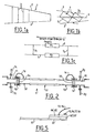
- the figure 1a is a schematic sectional view of an aircraft wing portion 1 which comprises a structure 2 made of composite material having a linear resistance of 10 3 ⁇ / m and stiffening elements 3 made of a conducting material such as aluminum.
- One or more fuel transport tubes 5 ( figure 1b ) are integral at their ends with two structural elements 3 1 and 3 2 .
- the tube shown in figure 2 has a central section 51 for example epoxy resin filled with glass fibers and carbon black, which has a resistivity of between 10 5 and 10 6 ⁇ .m.
- the resistivity being high, it is indeed a load of glass fibers, which imposes a relatively high thickness to ensure the mechanical properties.
- the end sections 52 and 53 are made of conductive material, for example Al, and are extended by conductive end connectors 54 and 55. Conductive wires 13 and 14 make it possible to electrically connect the end sections 52 and 53 and the conductive connectors 11 and 12 which are traversed by the fuel. Sealing is provided by electrically insulating joints 15 and 16.
- the conductor patches 11 and 12 are fixed on the 3 elements of Structure 1 and 3 2.
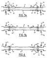
- a tube 6 whose length is for example between 0.2 m and 1.2 m, has a central section 61 of conductive material whose linear resistance is less than 10 4 ⁇ / m, while the end sections have a useful resistor of between 100 k ⁇ and 500 k ⁇ , the useful resistor being defined as the resistor R 3 or R 4 of the end section 62 or 63 and, if appropriate, of the connection 64, 65, 64 'or 65' between the central section 61 and point 13 'and 14' where the wire 13 or 14 makes contact with the end section 62 or 63 extended by a conductive or insulating end connection 64 or 65.
- An end connection 64 and / or 65 may be made of a glued or welded thermoplastic material (for example polyamide, PEEK, PEI) optionally loaded with fibers, especially carbon fibers, to reinforce it and regulate its conductivity, or else a thermosetting material whose conductivity may be adjusted by means of fibers carbon or aut conductive rests such as graphite or nanoparticles.
- the central section 61 is for example a thermosetting material, or elastomer with conductive fillers to strengthen and adjust its conductivity, is for example epoxy resin or polyamide loaded with conductive fillers including carbon fibers. In the central section 61, which occupies about 80% to 95% of the length of the tube 6, the presence of glass fibers is thus avoided. Preferably, it has only conductive fillers.
- the end sections 62 and 63 are made of a material, for example a polyamide, filled with glass fibers, and conductive fillers, for example carbon black.
- the figure 3b illustrates another embodiment that differs from the figure 3a by the presence of conductive seals 17 and 18 in place of the son 13 and 14. In this case, the entire length of the end sections 62 and 63 is taken into account to define the resistors R 3 and R 4 .
- the central section 61 has a low resistance, it is possible to reduce its weight, it is not necessary to add glass fibers (the carbon fibers are sufficient), so that its thickness can be reduced. while satisfying the required mechanical properties, resulting in a weight gain of, for example, 20% to 30%. Since the end sections 62 and 63 are not made of metal, a gain in weight generally greater than 15% is obtained.
- the central section 61 may comprise long carbon fibers in a thermoplastic material, carbon fibers in a thermosetting material, for example an epoxy resin, or a filled thermoplastic or a conductive rubber loaded with a conductive filler, for example carbon fibers. short (length ⁇ 1mm).
- the central section 61 has a lower resistance than in the prior art is favorable to the evacuation of charges, while in case of lightning, the tube 6 which has a significantly higher electrical resistance than the structure 2 avoids a short circuit.
- the contact is made only on one side by one or two son 14 and 14 '.
- the end section 63 it is possible for the end section 63 to be made of a more conductive material than the other end section 61, for example the same material as the central section 62.
- the figure 5 is a variant in which the end sections 62 and 63 are constituted by an extension of the central section 61 which is surrounded by a resistive sleeve 62 'or 63', itself surrounded by an end connection 64 'or 65 .
- the resistive sleeve may be a resistive glue or a rubber or a thermoplastic filled with glass fibers.
- the end fitting 64 'or 65 may be conductive (for example metal) or resistive.
- the contacting by the wire 13, 14 is effected by the end connection 64 'or 65'.
- the value of its resistance is to be taken into account for the calculation of the useful resistance.
Landscapes
- Engineering & Computer Science (AREA)
- General Engineering & Computer Science (AREA)
- Mechanical Engineering (AREA)
- Business, Economics & Management (AREA)
- Health & Medical Sciences (AREA)
- Public Health (AREA)
- Aviation & Aerospace Engineering (AREA)
- Emergency Management (AREA)
- Rigid Pipes And Flexible Pipes (AREA)
- Compositions Of Macromolecular Compounds (AREA)
- Laminated Bodies (AREA)
- Conductive Materials (AREA)
- Control Of The Air-Fuel Ratio Of Carburetors (AREA)
- Gasket Seals (AREA)
Claims (10)
- Vorrichtung zum Fluidtransport, welche dazu bestimmt ist, in eine nicht elektrisch isolierende Struktur eingebaut zu werden, insbesondere aus Verbundmaterial und mit einem elektrisch resistiven Rohr und leitenden Ansatzstücken, welche ein Mittel zur Befestigung an der Struktur aufweisen, dadurch gekennzeichnet, dass das Rohr umfasst:- einen Zentralabschnitt (61) mit einem Widerstand von weniger als 104 Ω pro Längenmeter,- zwei Endabschnitte (62, 63), von welchen wenigstens einer einen Nutzwiderstand aufweist, der zwischen 100 kΩ und 500 kΩ enthalten ist, und welche in einem Endanschluss (64, 65) enden,und wenigstens ein leitendes Element (13, 14, 14', 17, 18), welches einen Endabschnitt mit einem genannten Nutzwiderstand, der zwischen 100 kΩ und 500 kΩ enthalten ist, und ein leitendes Ansatzstück elektrisch verbindet, wobei der Nutzwiderstand definiert ist als der Wert des Widerstands des Endabschnitts zwischen dem Zentralabschnitt und dem leitenden Element.
- Vorrichtung nach Anspruch 1, dadurch gekennzeichnet, dass sie zwei Endabschnitte (62, 63), welche einen Nutzwiderstand aufweisen, der zwischen 100 kΩ und 500 kΩ enthalten ist, und zwei genannte leitende Elemente (13, 14, 17, 18), welche jeweils einen Endabschnitt mit dem entsprechenden leitenden Ansatzstück (11, 12) verbinden, aufweist.
- Vorrichtung nach einem der Ansprüche 1 oder 2, dadurch gekennzeichnet, dass wenigstens ein leitendes Element ein leitender Draht (13, 14) ist.
- Vorrichtung nach einem der Ansprüche 1-3, dadurch gekennzeichnet, dass wenigstens ein leitendes Element eine leitende Dichtung (17, 18) ist.
- Vorrichtung nach Anspruch 1, dadurch gekennzeichnet, dass sie zwei Endabschnitte (62, 63), welche einen Nutzwiderstand aufweisen, der zwischen 100 kΩ und 500 kΩ enthalten ist, und wenigstens ein genanntes leitendes Element (14, 14'), welches an einem einzigen Endabschnitt (63) angeordnet ist und diesen mit dem entsprechenden leitenden Ansatzstück verbindet, aufweist.
- Vorrichtung nach Anspruch 1, dadurch gekennzeichnet, dass sie einen ersten Endabschnitt (62), welcher einen Widerstand aufweist, der zwischen 100 kΩ und 500 kΩ enthalten ist, und einen zweiten Endabschnitt (63), welcher einen Nutzwiderstand aufweist, der geringer ist als dieser Wert, und wenigstens ein genanntes leitendes Element (14, 14'), welches an dem zweiten Endabschnitt (63) angeordnet ist und diesen mit dem entsprechenden leitenden Ansatzstück (12) verbindet, aufweist.
- Vorrichtung nach einem der vorhergehenden Ansprüche, dadurch gekennzeichnet, dass der Zentralabschnitt (61) aus einem thermoplastischen, einem wärmehärtbaren oder einem elastomeren Material mit leitenden Füllstoffen ist.
- Vorrichtung nach einem der vorhergehenden Ansprüche, dadurch gekennzeichnet, dass wenigstens ein Endabschnitt (62) aus einem mit Glasfasern und leitenden Füllstoffen gefüllten Material ist.
- Vorrichtung nach einem der vorhergehenden Ansprüche, dadurch gekennzeichnet, dass wenigstens ein Endanschluss (64, 65) aus einem thermoplastischen oder wärmehärtbaren Material mit optional leitenden Füllstoffen ist.
- Vorrichtung nach einem der vorhergehenden Ansprüche, dadurch gekennzeichnet, dass wenigstens ein Endabschnitt (62, 63) einen Fortsatz (61') des Zentralabschnitts (61) aufweist, welches aufeinanderfolgend von einer leitenden Muffe (62', 63') und einem Endanschluss (64', 65') umgeben ist.
Applications Claiming Priority (1)
| Application Number | Priority Date | Filing Date | Title |
|---|---|---|---|
| FR0806526A FR2938624B1 (fr) | 2008-11-20 | 2008-11-20 | Dispositif de transport de fluide notamment pour carburant |
Publications (2)
| Publication Number | Publication Date |
|---|---|
| EP2189702A1 EP2189702A1 (de) | 2010-05-26 |
| EP2189702B1 true EP2189702B1 (de) | 2012-02-01 |
Family
ID=40908081
Family Applications (1)
| Application Number | Title | Priority Date | Filing Date |
|---|---|---|---|
| EP09290839A Active EP2189702B1 (de) | 2008-11-20 | 2009-11-05 | Vorrichtung zum Transport eines Fluids, insbesondere Kraftstoff |
Country Status (5)
| Country | Link |
|---|---|
| US (1) | US8356635B2 (de) |
| EP (1) | EP2189702B1 (de) |
| AT (1) | ATE544032T1 (de) |
| ES (1) | ES2384204T3 (de) |
| FR (1) | FR2938624B1 (de) |
Cited By (1)
| Publication number | Priority date | Publication date | Assignee | Title |
|---|---|---|---|---|
| AU2013205236B2 (en) * | 2012-06-08 | 2017-02-09 | The Boeing Company | Fluid transport system for preventing electrical discharge |
Families Citing this family (18)
| Publication number | Priority date | Publication date | Assignee | Title |
|---|---|---|---|---|
| GB201014699D0 (en) | 2010-09-06 | 2010-10-20 | Airbus Uk Ltd | A pipe connector |
| WO2012088055A1 (en) * | 2010-12-20 | 2012-06-28 | Eaton Corporation | Aircraft fuel handling system |
| FR2975162B1 (fr) | 2011-05-09 | 2014-03-21 | Airbus Operations Sas | Dispositif de raccordement de tuyauteries carburant pour aeronef |
| US10180201B2 (en) * | 2011-09-29 | 2019-01-15 | The Boeing Company | Electrostatic bonding of coaxial tubing |
| FR2983276B1 (fr) * | 2011-11-30 | 2014-08-22 | Airbus Operations Sas | Dispositif de fixation d'un circuit de transport de fluide a un element de la structure d'un aeronef et aeronef associe |
| US9169029B2 (en) * | 2012-06-08 | 2015-10-27 | The Boeing Company | Conductive coupling assembly |
| US9739402B2 (en) * | 2013-03-04 | 2017-08-22 | Eaton Corporation | Electrically conductive seals for fluid conveyance systems |
| CN103895869B (zh) * | 2014-04-10 | 2016-02-24 | 哈尔滨飞机工业集团有限责任公司 | 飞机油箱防闪电通气管路结构 |
| GB2542121A (en) | 2015-09-08 | 2017-03-15 | Airbus Operations Ltd | Pipe installation |
| EP3428499B1 (de) * | 2017-07-14 | 2021-03-17 | Crompton Technology Group Limited | Zusammengesetzte flüssigkeitsübertragungsleitung |
| GB2575977A (en) * | 2018-07-30 | 2020-02-05 | Airbus Operations Ltd | Support member |
| EP3608093B1 (de) | 2018-08-10 | 2024-04-17 | Crompton Technology Group Limited | Verbundverbinder und verfahren zur herstellung davon |
| EP3608095B1 (de) | 2018-08-10 | 2026-05-06 | Crompton Technology Group Limited | Verbundverbinder und verfahren zur herstellung davon |
| EP3608089B1 (de) | 2018-08-10 | 2022-10-12 | Crompton Technology Group Limited | Verbundverbinder und verfahren zur herstellung davon |
| EP3608091B1 (de) | 2018-08-10 | 2025-10-01 | Crompton Technology Group Limited | Verbundverbinder und verfahren zur herstellung davon |
| EP3608094B1 (de) * | 2018-08-10 | 2024-09-25 | Crompton Technology Group Limited | Verbundverbinder und verfahren zur herstellung davon |
| EP3608092B1 (de) | 2018-08-10 | 2023-06-28 | Crompton Technology Group Limited | Verbundverbinder und verfahren zur herstellung davon |
| EP3636551B1 (de) * | 2018-10-09 | 2021-06-23 | Bombardier Inc. | Flugzeugkraftstoffsystem und zugehöriges verfahren |
Family Cites Families (10)
| Publication number | Priority date | Publication date | Assignee | Title |
|---|---|---|---|---|
| US3580983A (en) * | 1969-12-03 | 1971-05-25 | Nat Catheter Corp | Conductive line tube |
| FR2379143A1 (fr) * | 1977-01-27 | 1978-08-25 | Superflexit | Procede permettant de rendre semi-conducteur de l'electricite un tuyau flexible |
| FR2617568B1 (fr) * | 1987-07-02 | 1989-10-20 | Aerospatiale | Tube pour la circulation d'un fluide inflammable, et tuyauterie realisee a partir de tels tubes |
| GB8729316D0 (en) * | 1987-12-16 | 1988-01-27 | Shrinemark Ltd | Improvements relating to tube formation |
| US5921285A (en) * | 1995-09-28 | 1999-07-13 | Fiberspar Spoolable Products, Inc. | Composite spoolable tube |
| NO307096B1 (no) * | 1997-11-17 | 2000-02-07 | Aker Offshore Partner As | Korrosjonsbeskyttet metallkonstruksjon, for eksempel i form av en roerledning som kan inngå i et stooere roersystem |
| US6843274B1 (en) * | 2003-06-25 | 2005-01-18 | Air Systems International, Inc. | Electrically conductive confined space ventilator conduit formed of conductive polymer, electrical grounding circuit for ventilation system using same, and methods of using and forming same |
| DE102005013981B4 (de) * | 2005-03-26 | 2015-11-26 | Volkswagen Ag | Elektrisch leitfähige Steckkupplung zum Verbinden von fluidführenden Bauteilen |
| SE529417C2 (sv) * | 2005-12-22 | 2007-08-07 | Volvo Lastvagnar Ab | Ledningsnät för ett fordon |
| US20100025079A1 (en) * | 2008-07-31 | 2010-02-04 | Flynn William T | Electrical bonding device for telescoping fluid line assembly |
-
2008
- 2008-11-20 FR FR0806526A patent/FR2938624B1/fr not_active Expired - Fee Related
-
2009
- 2009-11-05 ES ES09290839T patent/ES2384204T3/es active Active
- 2009-11-05 EP EP09290839A patent/EP2189702B1/de active Active
- 2009-11-05 AT AT09290839T patent/ATE544032T1/de active
- 2009-11-10 US US12/615,567 patent/US8356635B2/en active Active
Cited By (1)
| Publication number | Priority date | Publication date | Assignee | Title |
|---|---|---|---|---|
| AU2013205236B2 (en) * | 2012-06-08 | 2017-02-09 | The Boeing Company | Fluid transport system for preventing electrical discharge |
Also Published As
| Publication number | Publication date |
|---|---|
| ES2384204T3 (es) | 2012-07-02 |
| ATE544032T1 (de) | 2012-02-15 |
| FR2938624A1 (fr) | 2010-05-21 |
| US8356635B2 (en) | 2013-01-22 |
| FR2938624B1 (fr) | 2010-12-24 |
| EP2189702A1 (de) | 2010-05-26 |
| US20100122749A1 (en) | 2010-05-20 |
Similar Documents
| Publication | Publication Date | Title |
|---|---|---|
| EP2189702A1 (de) | Vorrichtung zum Transport eines Fluids, insbesondere Kraftstoff | |
| EP2522576B1 (de) | Anschlussvorrichtung für die Kraftstoffrohrleitungen eines Luftfahrzeugs | |
| CA2767178C (fr) | Dispositif de protection de tuyauteries contre la foudre | |
| EP1858116B1 (de) | Elektrischer abgeschirmter Kabelbaum, insbesondere für Flugzeugmotor | |
| US8654499B2 (en) | Pipe connector | |
| EP2177803B1 (de) | Treibstoffleitung für Flug-oder Raumfahrzeuge, ihre Herstellungsmethode und Flügel mit entsprechender Leitung | |
| EP2672156B1 (de) | Verbundrohre für ein Flüssigkeitsfördersystem | |
| CN106494607A (zh) | 管道装置 | |
| RU2718659C2 (ru) | Электрический изолятор, способ его формирования и гидравлическая система | |
| EP2497174B1 (de) | System zur stromleitung durch eine wand | |
| EP2953203B1 (de) | Vorrichtung zur energieübertragung von einem milieu in ein anderes | |
| WO2014102029A1 (fr) | Ligne d'echappement de vehicule automobile comportant une rotule perfectionnee | |
| WO2020183111A1 (fr) | Dispositif de raccordement d'un harnais électrique à l'arrière d'un connecteur électrique | |
| CA3043389A1 (fr) | Corps de jonction, raccords, systeme hydraulique pour le passage d'un fluide entre deux circuits hydrauliques, procede de montage associes | |
| EP3891768B1 (de) | Kopplungsvorrichtung mit bauteile zur kopplung einer elektrischen verbindung und einem leitfähigen element | |
| EP4213322A1 (de) | Verbindungsanordnung zwischen zwei elektrischen kabeln | |
| BE533272A (de) | ||
| FR2626133A1 (fr) | Cordon electrique de chauffage | |
| BE891703A (fr) | Raccord etanche destine aux tuyauteries transportant du gaz ou des produits chimiques |
Legal Events
| Date | Code | Title | Description |
|---|---|---|---|
| PUAI | Public reference made under article 153(3) epc to a published international application that has entered the european phase |
Free format text: ORIGINAL CODE: 0009012 |
|
| AK | Designated contracting states |
Kind code of ref document: A1 Designated state(s): AT BE BG CH CY CZ DE DK EE ES FI FR GB GR HR HU IE IS IT LI LT LU LV MC MK MT NL NO PL PT RO SE SI SK SM TR |
|
| AX | Request for extension of the european patent |
Extension state: AL BA RS |
|
| 17P | Request for examination filed |
Effective date: 20101125 |
|
| GRAP | Despatch of communication of intention to grant a patent |
Free format text: ORIGINAL CODE: EPIDOSNIGR1 |
|
| GRAS | Grant fee paid |
Free format text: ORIGINAL CODE: EPIDOSNIGR3 |
|
| GRAA | (expected) grant |
Free format text: ORIGINAL CODE: 0009210 |
|
| AK | Designated contracting states |
Kind code of ref document: B1 Designated state(s): AT BE BG CH CY CZ DE DK EE ES FI FR GB GR HR HU IE IS IT LI LT LU LV MC MK MT NL NO PL PT RO SE SI SK SM TR |
|
| REG | Reference to a national code |
Ref country code: GB Ref legal event code: FG4D Free format text: NOT ENGLISH |
|
| REG | Reference to a national code |
Ref country code: CH Ref legal event code: EP Ref country code: AT Ref legal event code: REF Ref document number: 544032 Country of ref document: AT Kind code of ref document: T Effective date: 20120215 |
|
| REG | Reference to a national code |
Ref country code: DE Ref legal event code: R096 Ref document number: 602009005036 Country of ref document: DE Effective date: 20120329 |
|
| REG | Reference to a national code |
Ref country code: NL Ref legal event code: VDEP Effective date: 20120201 |
|
| REG | Reference to a national code |
Ref country code: ES Ref legal event code: FG2A Ref document number: 2384204 Country of ref document: ES Kind code of ref document: T3 Effective date: 20120702 |
|
| LTIE | Lt: invalidation of european patent or patent extension |
Effective date: 20120201 |
|
| PG25 | Lapsed in a contracting state [announced via postgrant information from national office to epo] |
Ref country code: NL Free format text: LAPSE BECAUSE OF FAILURE TO SUBMIT A TRANSLATION OF THE DESCRIPTION OR TO PAY THE FEE WITHIN THE PRESCRIBED TIME-LIMIT Effective date: 20120201 Ref country code: LT Free format text: LAPSE BECAUSE OF FAILURE TO SUBMIT A TRANSLATION OF THE DESCRIPTION OR TO PAY THE FEE WITHIN THE PRESCRIBED TIME-LIMIT Effective date: 20120201 Ref country code: NO Free format text: LAPSE BECAUSE OF FAILURE TO SUBMIT A TRANSLATION OF THE DESCRIPTION OR TO PAY THE FEE WITHIN THE PRESCRIBED TIME-LIMIT Effective date: 20120501 Ref country code: HR Free format text: LAPSE BECAUSE OF FAILURE TO SUBMIT A TRANSLATION OF THE DESCRIPTION OR TO PAY THE FEE WITHIN THE PRESCRIBED TIME-LIMIT Effective date: 20120201 Ref country code: IS Free format text: LAPSE BECAUSE OF FAILURE TO SUBMIT A TRANSLATION OF THE DESCRIPTION OR TO PAY THE FEE WITHIN THE PRESCRIBED TIME-LIMIT Effective date: 20120601 |
|
| REG | Reference to a national code |
Ref country code: IE Ref legal event code: FD4D |
|
| PG25 | Lapsed in a contracting state [announced via postgrant information from national office to epo] |
Ref country code: GR Free format text: LAPSE BECAUSE OF FAILURE TO SUBMIT A TRANSLATION OF THE DESCRIPTION OR TO PAY THE FEE WITHIN THE PRESCRIBED TIME-LIMIT Effective date: 20120502 Ref country code: LV Free format text: LAPSE BECAUSE OF FAILURE TO SUBMIT A TRANSLATION OF THE DESCRIPTION OR TO PAY THE FEE WITHIN THE PRESCRIBED TIME-LIMIT Effective date: 20120201 Ref country code: PL Free format text: LAPSE BECAUSE OF FAILURE TO SUBMIT A TRANSLATION OF THE DESCRIPTION OR TO PAY THE FEE WITHIN THE PRESCRIBED TIME-LIMIT Effective date: 20120201 Ref country code: PT Free format text: LAPSE BECAUSE OF FAILURE TO SUBMIT A TRANSLATION OF THE DESCRIPTION OR TO PAY THE FEE WITHIN THE PRESCRIBED TIME-LIMIT Effective date: 20120601 Ref country code: FI Free format text: LAPSE BECAUSE OF FAILURE TO SUBMIT A TRANSLATION OF THE DESCRIPTION OR TO PAY THE FEE WITHIN THE PRESCRIBED TIME-LIMIT Effective date: 20120201 |
|
| REG | Reference to a national code |
Ref country code: AT Ref legal event code: MK05 Ref document number: 544032 Country of ref document: AT Kind code of ref document: T Effective date: 20120201 |
|
| PG25 | Lapsed in a contracting state [announced via postgrant information from national office to epo] |
Ref country code: CY Free format text: LAPSE BECAUSE OF FAILURE TO SUBMIT A TRANSLATION OF THE DESCRIPTION OR TO PAY THE FEE WITHIN THE PRESCRIBED TIME-LIMIT Effective date: 20120201 |
|
| PG25 | Lapsed in a contracting state [announced via postgrant information from national office to epo] |
Ref country code: RO Free format text: LAPSE BECAUSE OF FAILURE TO SUBMIT A TRANSLATION OF THE DESCRIPTION OR TO PAY THE FEE WITHIN THE PRESCRIBED TIME-LIMIT Effective date: 20120201 Ref country code: SI Free format text: LAPSE BECAUSE OF FAILURE TO SUBMIT A TRANSLATION OF THE DESCRIPTION OR TO PAY THE FEE WITHIN THE PRESCRIBED TIME-LIMIT Effective date: 20120201 Ref country code: IE Free format text: LAPSE BECAUSE OF FAILURE TO SUBMIT A TRANSLATION OF THE DESCRIPTION OR TO PAY THE FEE WITHIN THE PRESCRIBED TIME-LIMIT Effective date: 20120201 Ref country code: DK Free format text: LAPSE BECAUSE OF FAILURE TO SUBMIT A TRANSLATION OF THE DESCRIPTION OR TO PAY THE FEE WITHIN THE PRESCRIBED TIME-LIMIT Effective date: 20120201 Ref country code: SE Free format text: LAPSE BECAUSE OF FAILURE TO SUBMIT A TRANSLATION OF THE DESCRIPTION OR TO PAY THE FEE WITHIN THE PRESCRIBED TIME-LIMIT Effective date: 20120201 Ref country code: EE Free format text: LAPSE BECAUSE OF FAILURE TO SUBMIT A TRANSLATION OF THE DESCRIPTION OR TO PAY THE FEE WITHIN THE PRESCRIBED TIME-LIMIT Effective date: 20120201 Ref country code: CZ Free format text: LAPSE BECAUSE OF FAILURE TO SUBMIT A TRANSLATION OF THE DESCRIPTION OR TO PAY THE FEE WITHIN THE PRESCRIBED TIME-LIMIT Effective date: 20120201 |
|
| PG25 | Lapsed in a contracting state [announced via postgrant information from national office to epo] |
Ref country code: SK Free format text: LAPSE BECAUSE OF FAILURE TO SUBMIT A TRANSLATION OF THE DESCRIPTION OR TO PAY THE FEE WITHIN THE PRESCRIBED TIME-LIMIT Effective date: 20120201 |
|
| PLBE | No opposition filed within time limit |
Free format text: ORIGINAL CODE: 0009261 |
|
| STAA | Information on the status of an ep patent application or granted ep patent |
Free format text: STATUS: NO OPPOSITION FILED WITHIN TIME LIMIT |
|
| 26N | No opposition filed |
Effective date: 20121105 |
|
| PG25 | Lapsed in a contracting state [announced via postgrant information from national office to epo] |
Ref country code: AT Free format text: LAPSE BECAUSE OF FAILURE TO SUBMIT A TRANSLATION OF THE DESCRIPTION OR TO PAY THE FEE WITHIN THE PRESCRIBED TIME-LIMIT Effective date: 20120201 |
|
| REG | Reference to a national code |
Ref country code: DE Ref legal event code: R097 Ref document number: 602009005036 Country of ref document: DE Effective date: 20121105 |
|
| BERE | Be: lapsed |
Owner name: ESPA Effective date: 20121130 |
|
| PG25 | Lapsed in a contracting state [announced via postgrant information from national office to epo] |
Ref country code: BG Free format text: LAPSE BECAUSE OF FAILURE TO SUBMIT A TRANSLATION OF THE DESCRIPTION OR TO PAY THE FEE WITHIN THE PRESCRIBED TIME-LIMIT Effective date: 20120501 |
|
| PG25 | Lapsed in a contracting state [announced via postgrant information from national office to epo] |
Ref country code: BE Free format text: LAPSE BECAUSE OF NON-PAYMENT OF DUE FEES Effective date: 20121130 |
|
| PG25 | Lapsed in a contracting state [announced via postgrant information from national office to epo] |
Ref country code: MT Free format text: LAPSE BECAUSE OF FAILURE TO SUBMIT A TRANSLATION OF THE DESCRIPTION OR TO PAY THE FEE WITHIN THE PRESCRIBED TIME-LIMIT Effective date: 20120201 |
|
| PG25 | Lapsed in a contracting state [announced via postgrant information from national office to epo] |
Ref country code: MC Free format text: LAPSE BECAUSE OF NON-PAYMENT OF DUE FEES Effective date: 20121130 Ref country code: TR Free format text: LAPSE BECAUSE OF FAILURE TO SUBMIT A TRANSLATION OF THE DESCRIPTION OR TO PAY THE FEE WITHIN THE PRESCRIBED TIME-LIMIT Effective date: 20120201 |
|
| PG25 | Lapsed in a contracting state [announced via postgrant information from national office to epo] |
Ref country code: SM Free format text: LAPSE BECAUSE OF FAILURE TO SUBMIT A TRANSLATION OF THE DESCRIPTION OR TO PAY THE FEE WITHIN THE PRESCRIBED TIME-LIMIT Effective date: 20120201 Ref country code: LU Free format text: LAPSE BECAUSE OF NON-PAYMENT OF DUE FEES Effective date: 20121105 |
|
| REG | Reference to a national code |
Ref country code: CH Ref legal event code: PL |
|
| PG25 | Lapsed in a contracting state [announced via postgrant information from national office to epo] |
Ref country code: HU Free format text: LAPSE BECAUSE OF FAILURE TO SUBMIT A TRANSLATION OF THE DESCRIPTION OR TO PAY THE FEE WITHIN THE PRESCRIBED TIME-LIMIT Effective date: 20091105 Ref country code: LI Free format text: LAPSE BECAUSE OF NON-PAYMENT OF DUE FEES Effective date: 20131130 Ref country code: CH Free format text: LAPSE BECAUSE OF NON-PAYMENT OF DUE FEES Effective date: 20131130 |
|
| PG25 | Lapsed in a contracting state [announced via postgrant information from national office to epo] |
Ref country code: MK Free format text: LAPSE BECAUSE OF FAILURE TO SUBMIT A TRANSLATION OF THE DESCRIPTION OR TO PAY THE FEE WITHIN THE PRESCRIBED TIME-LIMIT Effective date: 20120201 |
|
| REG | Reference to a national code |
Ref country code: FR Ref legal event code: PLFP Year of fee payment: 7 |
|
| REG | Reference to a national code |
Ref country code: FR Ref legal event code: PLFP Year of fee payment: 8 |
|
| REG | Reference to a national code |
Ref country code: FR Ref legal event code: PLFP Year of fee payment: 9 |
|
| REG | Reference to a national code |
Ref country code: FR Ref legal event code: PLFP Year of fee payment: 10 |
|
| P01 | Opt-out of the competence of the unified patent court (upc) registered |
Effective date: 20230526 |
|
| PGFP | Annual fee paid to national office [announced via postgrant information from national office to epo] |
Ref country code: DE Payment date: 20251119 Year of fee payment: 17 |
|
| PGFP | Annual fee paid to national office [announced via postgrant information from national office to epo] |
Ref country code: GB Payment date: 20251121 Year of fee payment: 17 |
|
| PGFP | Annual fee paid to national office [announced via postgrant information from national office to epo] |
Ref country code: IT Payment date: 20251125 Year of fee payment: 17 |
|
| PGFP | Annual fee paid to national office [announced via postgrant information from national office to epo] |
Ref country code: FR Payment date: 20251121 Year of fee payment: 17 |
|
| PGFP | Annual fee paid to national office [announced via postgrant information from national office to epo] |
Ref country code: ES Payment date: 20251229 Year of fee payment: 17 |