EP2189691A1 - Absperrarmatur für ein Rohrleitungssystem - Google Patents
Absperrarmatur für ein Rohrleitungssystem Download PDFInfo
- Publication number
- EP2189691A1 EP2189691A1 EP09013983A EP09013983A EP2189691A1 EP 2189691 A1 EP2189691 A1 EP 2189691A1 EP 09013983 A EP09013983 A EP 09013983A EP 09013983 A EP09013983 A EP 09013983A EP 2189691 A1 EP2189691 A1 EP 2189691A1
- Authority
- EP
- European Patent Office
- Prior art keywords
- shut
- actuator
- fitting
- pipe
- valve
- Prior art date
- Legal status (The legal status is an assumption and is not a legal conclusion. Google has not performed a legal analysis and makes no representation as to the accuracy of the status listed.)
- Granted
Links
- 238000007789 sealing Methods 0.000 claims abstract description 38
- 238000011144 upstream manufacturing Methods 0.000 claims description 5
- 238000006073 displacement reaction Methods 0.000 claims description 3
- 230000000295 complement effect Effects 0.000 claims description 2
- 230000006835 compression Effects 0.000 claims 1
- 238000007906 compression Methods 0.000 claims 1
- 230000001419 dependent effect Effects 0.000 description 4
- 238000013461 design Methods 0.000 description 3
- 239000012530 fluid Substances 0.000 description 3
- 230000000694 effects Effects 0.000 description 2
- 238000000926 separation method Methods 0.000 description 2
- 238000005299 abrasion Methods 0.000 description 1
- 230000004888 barrier function Effects 0.000 description 1
- 230000000903 blocking effect Effects 0.000 description 1
- 238000006243 chemical reaction Methods 0.000 description 1
- 238000005336 cracking Methods 0.000 description 1
- 210000004907 gland Anatomy 0.000 description 1
- 238000010438 heat treatment Methods 0.000 description 1
- 238000009434 installation Methods 0.000 description 1
- 239000007788 liquid Substances 0.000 description 1
- 238000012423 maintenance Methods 0.000 description 1
- 230000004048 modification Effects 0.000 description 1
- 238000012986 modification Methods 0.000 description 1
- 238000012544 monitoring process Methods 0.000 description 1
- 238000012856 packing Methods 0.000 description 1
- 230000008439 repair process Effects 0.000 description 1
Images

Classifications
-
- F—MECHANICAL ENGINEERING; LIGHTING; HEATING; WEAPONS; BLASTING
- F16—ENGINEERING ELEMENTS AND UNITS; GENERAL MEASURES FOR PRODUCING AND MAINTAINING EFFECTIVE FUNCTIONING OF MACHINES OR INSTALLATIONS; THERMAL INSULATION IN GENERAL
- F16K—VALVES; TAPS; COCKS; ACTUATING-FLOATS; DEVICES FOR VENTING OR AERATING
- F16K3/00—Gate valves or sliding valves, i.e. cut-off apparatus with closing members having a sliding movement along the seat for opening and closing
- F16K3/02—Gate valves or sliding valves, i.e. cut-off apparatus with closing members having a sliding movement along the seat for opening and closing with flat sealing faces; Packings therefor
- F16K3/12—Gate valves or sliding valves, i.e. cut-off apparatus with closing members having a sliding movement along the seat for opening and closing with flat sealing faces; Packings therefor with wedge-shaped arrangements of sealing faces
Definitions
- the invention relates to a shut-off valve for a pipeline system with a valve housing provided on both sides with pipe connections and a shut-off element which can be inserted perpendicular to the pipe axis in a closed position, wherein the shut-off comprises an actuator and a number of elastic sealing elements, and wherein the pipe connections with Seating surfaces are provided for the shut-off.
- the DE 33 41 123 discloses a gate valve for a piping system with a number of slide plates and sealing surfaces and an axially displaceable poppet, which is provided with sealing surfaces and loaded by springs, wherein the slide plates have bores and wherein the valve cone is acted upon by the pressure of pending in the pipeline medium.
- a gate valve which comprises a housing provided with pipe connections on both sides with a hood and a hood associated with a screw jack bearing, the gate valve allows replacement of the spindle and the spindle bearing in the operation of the piping system by a seat in the hood Is formed sealing means for a closure body.
- the housing interior is connected via gaps between the slide plates and a spindle with a sealed from the valve cone pressure chamber. If the pressure in the housing interior exceeds the operating pressure prevailing on a slide plate, the valve cone lifts off its seating surface and allows so much medium to escape until the overpressure has been reduced.
- shut-off valves In high-energy piping systems, slide valves have always been used as shut-off elements for shutting off fluid flows.
- this type of shut-off valve is placed in a provided around the two shut-off with a seat around each pipe ends around a housing shut-off element for closing perpendicular to the pipe axis between the seats provided for the shut-off that the fluid flow is interrupted and the shut-off downstream pressed against the seat and thereby a Sealing is achieved.
- one-piece wedge and two-piece wedge or parallel plate slides differ essentially only in the way in which, during or after the movement of the shut-off element to the shut-off, which is perpendicular to the tube axis, its movement or that of the plates held by it in the direction of the pipe axis is achieved for sealing on the seats.
- the seal in the seat is made with plate-shaped elements, which leads to a dependent on the differential pressure and the pipe diameter load of the seats and their sealing surfaces when closing.
- the invention is therefore based on the object to provide a shut-off valve of the type mentioned, the structural elements are designed such that the achievable seat tightness is maintained even during and after the shutdown of high-energy fluid flows, so that the disadvantages of the previous solutions can be avoided.
- This object is achieved in that the achieved in the closed position distance between the actuator and the seating surfaces is designed such that a deformation that exceeds the limits of the elasticity of the sealing elements, is excluded.
- the invention is based on the consideration that one of the main causes of leaks conventional gate valves based on the seat and the seat seal of the shut-off absorb the entire load acting through the flowing medium and the differential pressure on the gate valve forces and thereby locally overloaded and to be damaged.
- the functional separation of the shut-off and sealing components according to the invention can produce a stable seal without the abrasion of the sealing surfaces produced during shut-off under duress.
- the advantages achieved by the invention are in particular that is significantly increased by the pressure-relieved seat seal in the closed state and by the pressure-relieved sliding of the sealing elements on the seats during the closing operation, the seat tightness and wear resistance of a gate valve and just when actuated with media-related applied differential pressure. This results in a higher reliability of the slide, such as in the shut-off of Bruchausströmung high-energy systems, especially in nuclear installations, and a lower susceptibility to wear with a correspondingly reduced maintenance and repair costs.
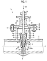
- the Fig. 1 shows in section the shut-off valve 1 of the pipeline system 2 in the half-open state, so that a medium flowing through the pipe system 2, not shown here medium can flow through the released from the shut-off 6 passage opening of the shut-off valve 1 therethrough.
- the shut-off valve 1 essentially comprises two main structural elements: the slide housing 4, which is fixedly connected to the piping system 2, and the shut-off element 6, which is arranged to be movable in the region of the slide housing 4 and in the exemplary embodiment has a wedge-shaped actuator 8.
- the slide housing 4 is connected at its attachment points or surfaces fixed to the piping system 2.
- the slide housing 4 comprises the slide dome 10 in the interior of the slide housing 4, which receives the shut-off element 6 in the partially or fully opened state. In this case, if necessary, a partial flow of the guided in the piping system 2 medium in the slide dome 10 penetrate and flow through it in the bypass to the main stream.
- the slide housing 4 is closed by the housing cover 12 by means of suitable sealing and sealing elements.
- this closure can be done by pins or screws 14 with suitable holding or securing elements 15, wherein the pins or screws 14 are guided through holes and the cover flange 16 of the housing cover 12 and the housing flange 18 of the valve body 4 pressure-tight interconnect.
- a lid seal 20 is provided for sealing.
- a drive for the lifting movement of the spindle 26 is arranged, which is not shown in the drawing.
- the arrangement of the spindle drive can be outside the pressure-carrying enclosure of the valve body, which is for this purpose penetrated by the lifting or threaded rod of the spindle 26 and sealed by a stuffing box 24.
- the shut-off 6 can be perpendicular to the pipe axis A of the in Fig. 1 illustrated opening position in the in Fig. 2 move shown closed position in which the media flow is interrupted by the piping system 2.
- self-media drives could also be arranged within the pressure-carrying enclosure.
- the shut-off element 6 essentially comprises the wedge-shaped actuator 8, which via the fixed thereto associated lifting rod of the spindle 26 perpendicular to the pipe axis A from the opening to the closed position (and back) is displaceable.
- the actuator 8 facing pipe ends are beveled according to the wedge contour, ie, in the sectional view in accordance with Fig. 1 a V-shaped recess in the hollow cylindrical pipe 2.
- the shut-off valve 1 is by a series of design measures for a particularly high density in the closed position at the same time low susceptibility to actuation with differential pressure - when the medium on one side of the shut-off 6 is at a different pressure level as the medium on the other side - designed, which are described in more detail below:
- the actuator 8 guide elements 34 a for example, recesses or grooves, which as complementary counterparts associated with the slider housing 4 guide elements 34b of the shut-off valve 1, such as strips or rods, are assigned.
- the preferably rail-like guide elements 34a, 34b are in shape, arrangement and Gleit vomausaus equilibrium designed so that on the one hand the acting upon actuation of the gate valve on the Absperrelement 6, axially directed (differential) pressure forces can be absorbed and removed into the valve body 4 and on the other hand the in the operation of the gate valve on the shut-off 6 acting flow and spindle forces do not lead to a tilting of the shut-6.
- axially directed (differential) pressure forces can be absorbed and removed into the valve body 4 and on the other hand the in the operation of the gate valve on the shut-off 6 acting flow and spindle forces do not lead to a tilting of the shut-6.
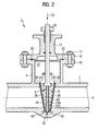
- Fig. 2 shows the shut-off 6 in the pipe 2 closing state.
- the threaded rod of the spindle 26 with its associated wedge-shaped actuator 8 is in the lowest achievable, necessary for the complete shut-off position.
- the guide elements 34a and 34b prevent an excessive pressing of the shut-off element 6 against the end or seat surfaces 36 or 38 of the pipeline system 2 which are located in the direction of the resulting pressure force. Without the guide elements 34a and 34b, both when the shut-off element 6 is inserted into the closed position as well as remaining in this closed position, a differential pressure-dependent force both on the seat located in the direction of compressive force seats 36 or 38 and on this side of the actuator 8 arranged to act on the seats 36 and 38 leaning sealing elements 48 or 50 act. This could lead to an excess beyond the elastic limit load and deformation of the sealing elements 48 and 50 and irreversibly damage them.
- sealing elements 48, 50 are mounted.
- elastic sealing rings or ring seals 48, 50 provided with respect to arrangement position and diameter on the them in the Closure state of the gate valve opposite pipe seat ring surfaces, that are tuned to the annular end or seat surfaces 36, 38.
- the nature and geometry of the ring seals 48 and 50, in particular their axial extent and elasticity, in relation to the gap width of the respective annular gap 54 or 56 given in the closure state are selected so that the respective ring seal 48 or 50 in the closed state of the shut-off element 6 with the necessary surface pressure to achieve a sufficient tightness, but if possible not beyond, elastically deformed and compressed. This is at the same time an undesirable tension or blocking of the shut-off 6 excluded in the closed position, which could otherwise be caused by thermal expansion of the valve body or the spindle 26 as a result of ambient or media-induced temperature transients.
- the (cross-sectional) geometry of the respective ring seal 48, 50 is designed by suitable choice of its inner and outer diameter so that it acts self-sealing with increasing differential pressure in the flow direction of the medium guided in the pipeline system 2.
- Fig. 3 is for the guided in the piping system 2 medium a preferred flow direction 3, here flowing from right to left, provided.
- elastic ring seal 50 on the actuator 8 side facing a larger diameter than on the actuator 8 facing away from the seat surface 38 side facing. Seen in section, the annular seal 50 thus bulges inwards, starting from the actuator 8, inwards toward the pipeline axis A and rests there against the annular seating surface 38.
- both ring seals 48, 50 have a larger wedge-side and a smaller seat-side diameter. This ensures that - regardless of the intended flow direction of the medium in the piping system 2 - a in incompressible media (liquids) possibly building up overpressure in the slide dome 10, z. B. by heating trapped in the slide dome 10 volumes, can automatically degrade into the piping system 2.
- the pressure built up in the slider dome 10 counteracts namely the elastic bias of the ring seal 48 and 50 and lifts them from their sealing seat on the seat surface 36 and 38 of the piping system 2 such that under pressure medium standing from the slide dome 10 in the piping system 2 can escape, so that an impermissible pressure in the slide dome 10 is avoided. Additional measures against impermissible housing pressure build-up are therefore not necessary.
- ring seals 48, 50 could also be fastened to the seat surfaces 36, 38 instead of the actuator 8.
Landscapes
- Engineering & Computer Science (AREA)
- General Engineering & Computer Science (AREA)
- Mechanical Engineering (AREA)
- Sliding Valves (AREA)
- Quick-Acting Or Multi-Walled Pipe Joints (AREA)
- Lift Valve (AREA)
Abstract
Description
- Die Erfindung bezieht sich auf eine Absperrarmatur für ein Rohrleitungssystem mit einem beidseits mit Rohranschlüssen versehenen Schiebergehäuse und mit einem Absperrelement, das senkrecht zur Rohrleitungsachse in eine Schließstellung einschiebbar ist, wobei das Absperrelement ein Stellglied und eine Anzahl von elastischen Dichtelementen umfasst, und wobei die Rohranschlüsse mit Sitzflächen für das Absperrelement versehen sind.
- Die
DE 33 41 123 offenbart einen Absperrschieber für ein Rohrleitungssystem mit einer Anzahl von Schieberplatten und Dichtflächen sowie einem axial verschiebbaren Ventilkegel, der mit Dichtflächen versehen und durch Federn belastet ist, wobei die Schieberplatten Bohrungen aufweisen und wobei der Ventilkegel durch den Druck des in der Rohrleitung anstehenden Mediums beaufschlagbar ist. - In der
EP 0 355 301 ist ein Absperrschieber beschrieben, der ein beidseits mit Rohranschlüssen versehenes Gehäuse mit einer Haube und einen der Haube zugeordneten Deckel mit einer Schraubspindellagerung umfasst, wobei der Absperrschieber ein Auswechseln der Spindel und der Spindellagerung auch im Betrieb des Rohrleitungssystems ermöglicht, indem in der Haube ein Sitz mit Dichtmitteln für einen Verschlusskörper ausgebildet ist. - Bei einem aus der
DE 2 806 737 bekannten Absperrschieber ist das Gehäuseinnere über Spalten zwischen den Schieberplatten und einer Spindel mit einem von dem Ventilkegel verschlossenen Druckraum verbunden. Überschreitet der Druck im Gehäuseinnenraum den an einer Schieberplatte anstehenden Betriebsdruck, hebt der Ventilkegel von seiner Sitzfläche ab und lässt so viel Medium entweichen, bis der Überdruck abgebaut ist. - In hochenergetischen Rohrleitungssystemen werden seit jeher Schieber als Absperrelemente zum Absperren von Fluidströmen eingesetzt. Bei dieser Art von Absperrarmatur wird in einem um die beiden zur Absperrung mit je einer Sitzfläche versehenen Rohrleitungsenden herum angeordneten Gehäuse ein Absperrelement zum Schließen senkrecht zur Rohrleitungsachse so zwischen die für das Absperrelement vorgesehenen Sitze geschoben, dass der Fluidstrom unterbrochen und das Absperrelement stromabwärts gegen den Sitz gedrückt und dadurch auch eine Abdichtung erzielt wird.
- Hierbei unterscheidet man je nach Ausführung in einteilige Keilscheiber sowie zweiteilige Keil- oder Parallelplattenschieber. Diese Schieberarten unterscheiden sich im Wesentlichen nur in der Art, wie während oder nach der zur Rohrachse senkrechten Bewegung des Absperrelementes zur Absperrung seine Bewegung oder diejenige der von ihm gehaltenen Platten in Richtung der Rohrleitungsachse zur Abdichtung auf den Sitzen erwirkt wird.
- Allen genannten Arten gemeinsam ist, dass die Abdichtung im Sitz mit plattenförmigen Elementen vorgenommen wird, die beim Schließen zu einer vom Differenzdruck und vom Rohrleitungsdurchmesser abhängigen Belastung der Sitze und ihrer Dichtflächen führt.
- Dabei kommt es durch die unter Last erzwungene Gleitbewegung der Dichtelemente in Richtung der Rohrleitungsachse je nach Funktionsprinzip der unterschiedlichen Schieberarten zu ungleichförmigen Bewegungen und in deren Folge möglicherweise zu örtlichen Flächenpressungsüberhöhungen im Sitz und in der Regel zu Beschädigungen auf den so belasteten Sitzbereichen, was letztendlich mit einem Verlust der Sitzdichtheit einhergeht.
- Durch die unter Last erzwungene gleitende Axialbewegung des Stellgliedes oder seiner Dichtplatten kommt es zu Zwängungen und Verschleiß an den Gleitflächen und rückwirkend zu Querkräften auf den Spindeltrieb, die sich besonders bei herkömmlichen Trapezgewindespindeln in lastabhängigen Faktoren für die Umwandlung von Drehmoment in Spindelkraft (Rate of Loading Effect) auswirken.
- Der Erfindung liegt daher die Aufgabe zugrunde, eine Absperrarmatur der genannten Art anzugeben, deren konstruktive Elemente derart ausgeführt sind, dass die erzielbare Sitzdichtheit auch bei und nach der Absperrung von hochenergetischen Fluidströmen erhalten bleibt, so dass die Nachteile der bisherigen Lösungen vermieden werden können.
- Diese Aufgabe wird erfindungsgemäß dadurch gelöst, dass der in der Schließstellung erzielte Abstand zwischen dem Stellglied und den Sitzflächen derart ausgelegt ist, dass eine Verformung, die die Grenzen der Elastizität der Dichtelemente überschreitet, ausgeschlossen ist.
- Vorteilhafte Ausgestaltungen der Erfindung sind Gegenstand der Unteransprüche und gegen im übrigen aus der detaillierten Figurenbeschreibung hervor.
- Die Erfindung geht von der Überlegung aus, dass eine der Hauptursachen für Undichtigkeiten herkömmlicher Absperrschieber darauf basiert, dass die Sitzfläche und die Sitzabdichtung des Absperrelementes die gesamte Last der durch das strömende Medium und durch den Differenzdruck auf den Absperrschieber wirkenden Kräfte aufnehmen und dadurch lokal überlastet und beschädigt werden. Die erfindungsgemäß verwirklichte funktionale Trennung der für das Absperren und für das Abdichten vorgesehenen Komponenten kann hingegen eine beständige Abdichtung ohne die beim Absperren unter Zwang erzeugte Abnutzung der Dichtungsflächen bewirken.
- Mit anderen Worten: Durch die konstruktive Trennung der beiden Funktionen "Absperren" und "Dichten", die von unabhängig voneinander wirkendenden, funktionell entkoppelten Konstruktionselementen übernommen werden, entfällt die von Absperrschiebern konventioneller Bauart bekannte Abstützung des Stellgliedes auf den Sitzflächen des Rohrleitungssystems, die dort je nach vorliegendem Differenzdruck zu sehr hohen Flächenlasten auf die Sitzflächen und auf die zwischen den Sitzflächen und dem Stellglied angeordneten Dichtelemente führen kann. Indem dies nunmehr konsequent vermieden ist, ist bei geeigneter Dimensionierung der Dichtelemente erreichbar, dass diese nur noch im Elastizitätsbereich, aber nicht darüber hinaus belastet werden.
- Die mit der Erfindung erzielten Vorteile bestehen insbesondere darin, dass durch die druckentlastete Sitzabdichtung im Verschlusszustand und durch das druckentlastete Gleiten der Dichtelemente über die Sitzflächen während der Schließbetätigung die Sitzdichtheit und die Verschleißfestigkeit eines Absperrschiebers auch und gerade bei Betätigung mit medienbedingt anliegendem Differenzdruck wesentlich erhöht wird. Daraus resultiert eine höhere Zuverlässigkeit des Schiebers, etwa bei Absperrung von Bruchausströmung hochenergetischer Systeme, insbesondere bei kerntechnischen Anlagen, und eine geringere Verschleißanfälligkeit mit entsprechend verringertem Wartungs- und Instandhaltungsaufwand.
- Zwei verschiedene Ausführungsbeispiele der Erfindung werden nachfolgend anhand von Zeichnungen näher erläutert. Darin zeigen:
- Fig. 1
- eine Absperrarmatur mit einem in teilweise geöffneter Stellung befindlichen Absperrelement im Längsschnitt,
- Fig. 2
- die Absperrarmatur gemäß
Fig.1 in geschlossener Stellung des Absperrelementes, und - Fig. 3
- eine zweite Variante der Absperrarmatur mit einer gegenüber der Variante gemäß
Fig.1 undFig. 2 abgewandelten Dichtkonfiguration, ebenfalls im Längsschnitt. - Gleiche Teile sind in allen Figuren mit denselben Bezugszeichen versehen.
- Die
Fig. 1 zeigt im Schnitt die Absperrarmatur 1 des Rohrleitungssystems 2 im halb geöffneten Zustand, so dass ein das Rohrleitungssystem 2 durchströmendes, hier nicht dargestelltes Medium durch die vom Absperrelement 6 freigegebene Durchtrittsöffnung der Absperrarmatur 1 hindurch fließen kann. Die Absperrarmatur 1 umfasst im Wesentlichen zwei konstruktive Hauptelemente: das Schiebergehäuse 4, das fest mit dem Rohrleitungssystem 2 verbunden ist, sowie das Absperrelement 6, das im Bereich des Schiebergehäuses 4 beweglich angeordnet ist und im Ausführungsbeispiel ein keilförmiges Stellglied 8 aufweist. - Das Schiebergehäuse 4 ist an seinen Befestigungspunkten oder -flächen fest mit dem Rohrleitungssystem 2 verbunden. Das Schiebergehäuse 4 umfasst den Schieberdom 10 im Inneren des Schiebergehäuses 4, der das Absperrelement 6 im teilweise oder vollständig geöffneten Zustand aufnimmt. Dabei kann ggf. ein Teilstrom des im Rohrleitungssystem 2 geführten Mediums in den Schieberdom 10 eindringen und ihn im Bypass zum Hauptstrom durchfließen. Das Schiebergehäuse 4 ist durch den Gehäusedeckel 12 mittels geeigneter Dichtungs- und Verschlusselemente verschlossen. Beispielsweise kann diese Verschließung durch Stifte oder Schrauben 14 mit geeigneten Halte- oder Sicherungselementen 15 erfolgen, wobei die Stifte oder Schrauben 14 durch Durchbohrungen geführt sind und den Deckelflansch 16 des Gehäusedeckels 12 und den Gehäuseflansch 18 des Schiebergehäuses 4 druckdicht miteinander verbinden. Zur Abdichtung ist eine Deckeldichtung 20 vorgesehen.
- Oberhalb des Gehäusedeckels 12 ist ein Antrieb für die Hubbewegung der Spindel 26 angeordnet, der in der Zeichnung nicht dargestellt ist. Die Anordnung des Spindelantriebes kann außerhalb der druckführenden Umschließung des Armaturengehäuses liegen, welches hierzu von der Hub- bzw. Gewindestange der Spindel 26 durchdrungen und über eine Stopfbuchse 24 abgedichtet wird. Durch die Hubbewegung der Spindel 26 lässt sich das Absperrelement 6 senkrecht zur Rohrleitungsachse A von der in
Fig. 1 dargestellten Öffnungsstellung in die inFig. 2 dargestellte Schließstellung verschieben, in der der Medienfluss durch das Rohrleitungssystem 2 unterbrochen ist. In alternativer Ausgestaltung könnten Eigenmediumantriebe auch innerhalb der druckführenden Umschließung angeordnet sein. - Das Absperrelement 6 umfasst im Wesentlichen das keilförmige Stellglied 8, welches über die fest mit ihm verbundene Hubstange der Spindel 26 senkrecht zur Rohrleitungsachse A von der Öffnungs- in die Verschlussstellung (und zurück) verschiebbar ist. Die dem Stellglied 8 zugewandten Rohrleitungsenden sind entsprechend dessen Keilkontur angeschrägt, bilden also in der Schnittdarstellung gemäß
Fig. 1 eine V-förmige Ausnehmung in der hohlzylindrischen Rohrleitung 2. - Die Absperrarmatur 1 ist durch eine Reihe von konstruktiven Maßnahmen für eine besonders hohe Dichtigkeit in der Verschlussstellung bei zugleich geringer Verschleißanfälligkeit bei Betätigung mit Differenzdruck - wenn das Medium auf der einen Seite des Absperrelementes 6 sich auf einem anderen Druckniveau befindet wie das Medium auf der anderen Seite - ausgelegt, die nachfolgend näher beschrieben werden:
- Zur Vermeidung von gleitenden Bewegungen des Stellgliedes 8 in Richtung der Rohrleitungsachse A, die beim Öffnen und Schließen des Absperrschiebers durch den am Absperrelement 6 anstehenden Differenzdruck hervorgerufen werden könnten, weist das Stellglied 8 Führungselemente 34a auf, beispielsweise Ausnehmungen oder Nuten, denen als komplementäre Gegenstücke die mit dem Schiebergehäuse 4 verbundenen Führungselemente 34b der Absperrarmatur 1, beispielsweise Leisten oder Stangen, zugeordnet sind. Die vorzugsweise schienenartigen Führungselemente 34a, 34b sind in Form, Anordnung und Gleitflächenausführung so gestaltet, dass einerseits die bei der Betätigung des Absperrschiebers auf das Absperrelement 6 einwirkenden, axial gerichteten (Differenz-) Druckkräfte aufgenommen und in das Schiebergehäuse 4 abgetragen werden können und andererseits die bei der Betätigung des Absperrschiebers auf das Absperrelement 6 einwirkenden Strömungs- und Spindelkräfte nicht zu einer Verkippung des Absperrelementes 6 führen. Damit werden insbesondere lokale Überbeanspruchungen der Führungselemente 34a, 34b und unerwünschte Querkräfte, die auf den Spindelantrieb rückwirken könnten, vermieden bzw. ausgeglichen.
- Zu näheren Illustration zeigt die
Fig. 2 zeigt das Absperrelement 6 in dem die Rohrleitung 2 verschließenden Zustand. Die Gewindestange der Spindel 26 mit dem mit ihr verbundenen keilförmigen Stellglied 8 ist in der untersten erreichbaren, für das vollständige Absperren notwendigen Position. - In dieser Verschlussstellung ist das Absperrelement 6 gegen eine axiale, d. h. in Richtung der Rohrleitungsachse A gerichtete Kraft, die durch die Druckbeaufschlagung des auf das Absperrelement 6 einwirkenden Mediums und infolge des anstehenden Differenzdrucks verursacht ist, mittels der Führungselemente 34a und 34b gesichert. Diese Sicherung ist so gestaltet, dass insbesondere die der Hubstange der Spindel 26 gegenüberliegende Keilspitze 35 des Stellgliedes 8 gegen eine axiale Verschiebung oder Verkippung fixiert ist. Die Führungselemente 34a und 34b bilden also gewissermaßen ein Gegenlager für das am anderen Ende über die Spindel 26 gelagerte Absperrelement 6.
- Die Führungselemente 34a und 34b verhindern vor allem ein übermäßiges Anpressen des Absperrelements 6 gegen die in Richtung der resultierenden Druckkraft gelegenen Stirn- bzw. Sitzflächen 36 oder 38 der Rohrleitungssystems 2. Ohne die Führungselemente 34a und 34b würde sowohl beim Einbringen des Absperrelementes 6 in die Verschlussstellung als auch beim Verbleib in dieser Verschlussstellung eine differenzdruckabhängige Kraft sowohl auf die in Richtung der resultierenden Druckkraft gelegenen Sitzflächen 36 oder 38 als auch auf die auf dieser Seite des Stellglieds 8 angeordneten, sich an die Sitzflächen 36 bzw. 38 anlehnenden Dichtelemente 48 oder 50 wirken. Dies könnte zu einer über die Elastizitätsgrenze hinausgehenden Belastung und Verformung der Dichtelemente 48 und 50 führen und diese irreversibel schädigen.
- Durch die Anordnung der Führungselemente 34a und 34b ist somit eine direkte Krafteinleitung und Abstützung des Absperrelementes 6 in die / an den Stirn- bzw. Sitzflächen 36 oder 38 der Rohrleitung 2 vermieden, da die druckbedingt auf das Stellglied 8 einwirkenden, im Wesentlichen axial gerichteten Kräfte über die stabilen Führungselemente 34a, 34b in das Armaturengehäuse abgetragen werden. Verschleiß an den Sitzflächen 36, 38 und an den zugehörigen Dichtelementen 48, 50 tritt nicht auf, da diese nicht mit Stellkräften belastet sind.
- Wie bereits erwähnt, sind zur Gewährleistung einer sicheren Abdichtung des Strömungsweges im Verschlusszustand der Absperrarmatur 1 an dem keilförmigen Stellglied 8 beidseits Dichtelemente 48, 50 angebracht. Anstelle der bislang üblichen flächig ausgedehnten Dichtplatten, die auf den Keilflächen 44, 46 des Stellgliedes 8 aufliegen, sind vorliegend auf den Keilflächen 44, 46 befestigte bzw. mit ihnen fest verbundene elastische Dichtringe oder Ringdichtungen 48, 50 vorgesehen, die bezüglich Anordnungsposition und Durchmesser auf die ihnen im Verschlusszustand des Absperrschiebers gegenüberliegenden Rohrleitungs-Sitzringflächen, d. h. auf die ringförmigen Stirn- bzw. Sitzflächen 36, 38 abgestimmt sind.
- Durch eine Begrenzung des Hubweges des Absperrelementes 6 in Schließrichtung 52, die beispielsweise durch eine elektronische Überwachung und Steuerung des Spindelantriebs und/oder durch einen geeigneten mechanischen Festanschlag realisiert sein kann, ist sichergestellt, dass im Schließzustand entlang dem gesamten Umfang der Rohrleitung 2 ein Ringspalt 54 bzw. 56 mit einer wohldefinierten Spaltbreite zwischen der jeweiligen Keilfläche 44 bzw. 46 des vergleichsweise harten und unelastischen Stellgliedes 8 und der ihr zugewandten Sitzfläche 36 bzw. 38 der ebenfalls relativ harten und unelastischen Rohrleitung 2 verbleibt. Aufgrund der Führungselemente 34a, 34b, die eine axiale Verschiebung oder Verkippung des Absperrelementes 6 wirkungsvoll unterdrücken, wird die jeweils eingestellte Spaltbreite auch beim Vorliegen vergleichsweise hoher Differenzdrücke im Rohrleitungssystem 2 vergleichsweise genau eingehalten.
- Dabei ist die Beschaffenheit und Geometrie der Ringdichtungen 48 und 50, insbesondere deren axiale Ausdehnung und Elastizität, in Relation zu der im Verschlusszustand gegebenen Spaltbreite des jeweiligen Ringspaltes 54 bzw. 56 so gewählt, dass die jeweilige Ringdichtung 48 bzw. 50 im Verschlusszustand des Absperrelementes 6 mit der notwendigen Flächenpressung zur Erzielung einer ausreichenden Dichtigkeit, aber möglichst nicht darüber hinaus, elastisch verformt und zusammengepresst wird. Damit ist zugleich eine unerwünschte Verspannung oder Blockierung des Absperrelementes 6 in der Schließposition ausgeschlossen, die ansonsten durch Wärmedehnung des Armaturengehäuses oder der Spindel 26 infolge von umgebungs- oder medieninduzierten Temperaturtransienten hervorgerufen werden könnte.
- Vorzugsweise ist die (Querschnitts-) Geometrie der jeweiligen Ringdichtung 48, 50 dabei durch geeignete Wahl ihres Innen- und Außendurchmessers so ausgeführt, dass sie mit steigendem Differenzdruck in Strömungsrichtung des im Rohrleitungssystem 2 geführten Mediums selbstdichtend wirkt.
- Im Ausführungsbeispiel gemäß
Fig. 3 ist für das im Rohrleitungssystem 2 geführte Medium eine bevorzugte Durchflussrichtung 3, hier von rechts nach links strömend, vorgesehen. In daran besonders angepasster Ausgestaltung weist die in Durchflussrichtung 3 gesehen an der stromaufwärtigen Seite des keilförmigen Stellglieds 8 angeordnete elastische Ringdichtung 50 auf der dem Stellglied 8 zugewandten Seite einen größeren Durchmesser auf als auf der dem Stellglied 8 abgewandten, der Sitzfläche 38 zugewandten Seite. Die Ringdichtung 50 wölbt sich im Schnitt betrachtet also vom Stellglied 8 ausgehend nach innen zur Rohrleitungsachse A hin und liegt dort an der ringförmigen Sitzfläche 38 an. Durch diese Ausgestaltung der Ringdichtung 50 ist bei allen Druckverhältnissen innerhalb des Rohrleitungssystems 2 eine zuverlässige Abdichtung erzielbar, da das stromaufwärts im rechten Teil der Rohrleitung 2 vorgehaltene und auf das Stellglied 8 auftreffende Medium die elastische Ringdichtung 50 bei steigendem Mediendruck immer fester gegen die Sitzflächen 38 drückt, wodurch sich die Dichtwirkung gewissermaßen automatisch und besonders bedarfsgerecht erhöht. - Die in Durchflussrichtung 3 des Mediums gesehen auf der stromabwärtigen Seite des Stellgliedes 8 angeordnete elastische Ringdichtung 48 weist hingegen auf der dem Stellglied 8 zugewandten Seite einen kleineren Durchmesser auf als auf der dem Stellglied 8 abgewandten, der Sitzfläche 36 zugewandten Seite, wölbt sich also vom Stellglied 8 ausgehend nach außen von der Rohrleitungsachse A weg. Falls also infolge etwaiger Undichtigkeit der stromaufwärts angeordneten Ringdichtung 50 Medium von der stromaufwärts des Stellgliedes 8 liegenden (rechten) Rohrleitung in den Schieberdom 10 überströmt und dort zu einem Druckaufbau gegenüber der vergleichsweise weniger druckbelasteten stromabwärtigen (linken) Rohrleitung führt, wird die stromabwärtige elastische Ringdichtung 48 mit steigendem Druck im Schieberdom 10 immer stärker gegen die zugehörige Sitzfläche 36 angepresst.
- Man kann daher in Bezug auf die Dichtanordnung gemäß
Fig. 3 von einer "zweistufigen Dichtungsbarriere" bzw. einer "doppelten Abdichtung" sprechen, durch die bei geschlossenem Absperrschieber 6 eine Leckage von Strömungsmedium aus dem hochenergetischen, unter hohem Mediendruck stehenden Rohrleitungsabschnitt in den niederenergetischen Abschnitt besonders zuverlässig ausgeschlossen ist. - Bei der in
Fig.1 undFig. 2 dargestellten alternativen Ausgestaltung weisen beide Ringdichtungen 48, 50 einen größeren keilseitigen und einen kleineren sitzseitigen Durchmesser auf. Dadurch ist sichergestellt, dass - unabhängig von der vorgesehenen Strömungsrichtung des Mediums im Rohrleitungssystem 2 - ein sich ein bei inkompressiblen Medien (Flüssigkeiten) eventuell aufbauender Überdruck im Schieberdom 10, z. B. durch Erwärmung von im Schieberdom 10 eingeschlossenen Volumina, selbsttätig in das Rohrleitungssystem 2 abbauen kann. Der sich aufbauende Überdruck im Schieberdom 10 wirkt nämlich der elastischen Vorspannung der Ringdichtung 48 bzw. 50 entgegen und hebt diese von ihrem Dichtsitz auf der Sitzfläche 36 bzw. 38 des Rohrleitungssystems 2 derart ab, dass unter Überdruck stehendes Medium aus dem Schieberdom 10 in das Rohrleitungssystem 2 entweichen kann, so dass ein unzulässiger Überdruck im Schieberdom 10 vermieden wird. Zusätzliche Maßnahmen gegen unzulässigen Gehäusedruckaufbau sind daher nicht notwendig. - In beiden Fällen, d. h. sowohl bei der Variante gemäß
Fig. 1 undFig. 2 als auch bei der Variante gemäßFig. 3 , gilt: Für die Ringdichtungen 48 und 50 ist eine Verformung über den Elastizitätsbereich hinaus nicht vorgesehen, da der in der Verschlussstellung erzielte Abstand zwischen dem Stellglied 8 mit den an ihm befestigten Ringdichtungen 48, 50 und den Sitzflächen 36, 38 des Rohrleitungssystems 2 derart ausgelegt ist, dass eine Verformung, die die Grenzen der Elastizität der Ringdichtungen 48 und 50 überschreitet und somit eine dauerhafte Verformung mit einhergehender Rissbildung und dergleichen bewirken könnte, nicht erreicht wird. - In einer hier nicht dargestellten Abwandlung könnten unter Beibehaltung der oben erläuterten Grundprinzipien die Ringdichtungen 48, 50 auch an den Sitzflächen 36, 38 anstatt am Stellglied 8 befestigt sein.
-
- 1
- Absperrarmatur
- 2
- Rohrleitungssystem
- 3
- Durchflussrichtung
- 4
- Schiebergehäuse
- 6
- Absperrelement
- 8
- Stellglied
- 10
- Schieberdom
- 12
- Gehäusedeckel
- 14
- Schraube
- 15
- Halteelement
- 16
- Deckelflansch
- 18
- Gehäuseflansch
- 20
- Deckeldichtung
- 22
- Durchbohrung
- 24
- Stopfbuchspackung
- 26
- Spindel
- 28
- Aufnahme
- 30
- Bundring
- 34a, 34b
- Führungselement
- 35
- Keilspitze
- 36, 38
- Sitzfläche
- 44, 46
- Keilfläche
- 48, 50
- Dichtelement (Ringdichtung)
- 52
- Schließrichtung
- 54, 56
- Ringspalt
Claims (10)
- Absperrarmatur (1) für ein Rohrleitungssystem (2) mit einem beidseits mit Rohranschlüssen versehenen Schiebergehäuse (4) und mit einem Absperrelement (6), das senkrecht zur Rohrleitungsachse (A) in eine Schließstellung einschiebbar ist, wobei das Absperrelement (6) ein Stellglied (8) und eine Anzahl von elastischen Dichtelementen (48, 50) umfasst, und wobei die Rohranschlüsse mit Sitzflächen (36, 38) für das Absperrelement (6) versehen sind,
dadurch gekennzeichnet, dass
der in der Schließstellung erzielte Abstand zwischen dem Stellglied (8) und den Sitzflächen (36, 38) derart ausgelegt ist, dass eine Verformung der Dichtelemente (48, 50), die deren Grenzen der Elastizität überschreitet, ausgeschlossen ist. - Absperrarmatur (1) nach Anspruch 1, deren Stellglied (8) mindestens ein Führungselement (34a) aufweist, dem ein mit dem Schiebergehäuse (4) verbundenes komplementäres Führungselement (34b) zugeordnet ist, wobei die Führungselemente (34a, 34b) derart beschaffen sind, dass eine Verkippung oder eine Verschiebung des Stellgliedes (8) in Richtung der Rohrleitungsachse (A) verhindert ist.
- Absperrarmatur (1) nach Anspruch 2, deren Führungselemente (34a, 34b) derart ausgelegt sind, dass auf das Absperrelement (6) einwirkende Kräfte in Richtung der Rohrleitungsachse (A) über die Führungselemente (34a, 34b) in das Schiebergehäuse (4) abgetragen werden.
- Absperrarmatur (1) nach Anspruch 2 oder 3, wobei die Führungselemente (34a, 34b) des Schiebergehäuses (4) eine Anzahl von Leisten oder Stangen und die die Führungselemente (34a, 34b) des Stellgliedes (8) eine Anzahl von zugehörigen Ausnehmungen oder Nuten aufweisen.
- Absperrarmatur (1) nach einem der Ansprüche 1 bis 4, wobei der Hubweg des Absperrelementes (6) in Schließrichtung (52) durch einen Festanschlag derart begrenzt ist, dass eine inelastische Zusammenpressung der Dichtelemente (48, 50) beim Kontakt mit den zugehörigen Sitzflächen (36, 38) ausgeschlossen ist.
- Absperrarmatur (1) nach einem der Ansprüche 1 bis 5, wobei die Dichtelemente (48, 50) des Absperrelementes (6) jeweils als Ringdichtung ausgebildet sind.
- Absperrarmatur (1) nach Anspruch 6, wobei mindestens eine der am Stellglied (8) angeordneten Ringdichtungen (48, 50) auf ihrer der Sitzfläche (36, 38) der Rohrleitung zugewandten Seite einen kleineren Durchmesser als auf ihrer dem Stellglied (8) zugewandten Seite aufweist.
- Absperrarmatur (1) nach Anspruch 7, wobei jede der beiden am Stellglied (8) angeordneten Ringdichtungen (48, 50) auf ihrer der Sitzfläche (36, 38) der Rohrleitung zugewandten Seite einen kleineren Durchmesser als auf ihrer dem Stellglied (8) zugewandten Seite aufweist.
- Absperrarmatur (1) nach Anspruch 7, die für eine bevorzugte Flussrichtung (6) eines das Rohrleitungssystem (2) durchströmenden Mediums ausgelegt ist, wobei die auf der stromaufwärtigen Seite des Stellgliedes (8) angeordnete Ringdichtung (50) auf ihrer der Sitzfläche (38) zugewandten Seite einen kleineren Durchmesser aufweist als auf ihrer dem Stellglied (8) zugewandten Seite, und wobei die auf der stromabwärtigen Seite des Stellgliedes (8) angeordnete Ringdichtung (48) auf ihrer der Sitzfläche (36) zugewandten Seite einen größeren Durchmesser aufweist als auf ihrer dem Stellglied (8) zugewandten Seite.
- Absperrarmatur (1) nach einem der Ansprüche 1 bis 9, wobei das Stellglied (8) keilförmig ausgebildet ist.
Priority Applications (1)
| Application Number | Priority Date | Filing Date | Title |
|---|---|---|---|
| PL09013983T PL2189691T3 (pl) | 2008-11-25 | 2009-11-06 | Armatura odcinająca dla układu rurociągów |
Applications Claiming Priority (1)
| Application Number | Priority Date | Filing Date | Title |
|---|---|---|---|
| DE102008058932.2A DE102008058932B4 (de) | 2008-11-25 | 2008-11-25 | Absperrarmatur für ein Rohrleitungssystem |
Publications (2)
| Publication Number | Publication Date |
|---|---|
| EP2189691A1 true EP2189691A1 (de) | 2010-05-26 |
| EP2189691B1 EP2189691B1 (de) | 2012-10-10 |
Family
ID=41692905
Family Applications (1)
| Application Number | Title | Priority Date | Filing Date |
|---|---|---|---|
| EP09013983A Not-in-force EP2189691B1 (de) | 2008-11-25 | 2009-11-06 | Absperrarmatur für ein Rohrleitungssystem |
Country Status (6)
| Country | Link |
|---|---|
| EP (1) | EP2189691B1 (de) |
| AR (1) | AR074404A1 (de) |
| BR (1) | BRPI0904436A2 (de) |
| DE (1) | DE102008058932B4 (de) |
| ES (1) | ES2393834T3 (de) |
| PL (1) | PL2189691T3 (de) |
Cited By (1)
| Publication number | Priority date | Publication date | Assignee | Title |
|---|---|---|---|---|
| CN103267139A (zh) * | 2013-05-03 | 2013-08-28 | 无锡富盛阀业有限公司 | 一种闸阀 |
Citations (9)
| Publication number | Priority date | Publication date | Assignee | Title |
|---|---|---|---|---|
| US2984449A (en) * | 1959-06-26 | 1961-05-16 | Chapman Valve Mfg Co | Sealing means for valve closure |
| GB925949A (en) * | 1961-01-02 | 1963-05-15 | Crane Co | Improvements in fluid control gate valves |
| DE1675414A1 (de) * | 1967-02-10 | 1970-12-10 | Jean Gachot | Ventil mit prismatischem Verschlusskoerper |
| US3575380A (en) * | 1969-10-06 | 1971-04-20 | Chester A Siver | Gate valve and method of constructing same |
| DE2806737A1 (de) | 1978-02-17 | 1979-08-23 | Zikesch Gmbh C H | Absperrorgan, insbesondere ventil, absperrschieber o.dgl. |
| US4373242A (en) * | 1978-10-04 | 1983-02-15 | Allis-Chalmers Corporation | Method of manufacturing a wedge gate valve |
| DE3341123A1 (de) | 1983-11-12 | 1985-05-23 | Deutsche Babcock Werke AG, 4200 Oberhausen | Absperrschieber |
| EP0355301A2 (de) | 1988-08-23 | 1990-02-28 | Immanuel Jeschke | Absperrschieber |
| US5004210A (en) * | 1989-08-28 | 1991-04-02 | Magic Plastics | Gate valve |
Family Cites Families (2)
| Publication number | Priority date | Publication date | Assignee | Title |
|---|---|---|---|---|
| DE967994C (de) * | 1953-09-24 | 1958-01-02 | Pleiger Maschf Paul | Dichtelement aus Kunststoff bei Absperrorganen fuer stroemende Medien und Verfahren zu deren Herstellung |
| DE3320809A1 (de) * | 1983-06-09 | 1984-12-13 | Deutsche Babcock Werke AG, 4200 Oberhausen | Absperrschieber |
-
2008
- 2008-11-25 DE DE102008058932.2A patent/DE102008058932B4/de not_active Expired - Fee Related
-
2009
- 2009-11-06 EP EP09013983A patent/EP2189691B1/de not_active Not-in-force
- 2009-11-06 ES ES09013983T patent/ES2393834T3/es active Active
- 2009-11-06 PL PL09013983T patent/PL2189691T3/pl unknown
- 2009-11-24 BR BRPI0904436-1A patent/BRPI0904436A2/pt not_active Application Discontinuation
- 2009-11-25 AR ARP090104543A patent/AR074404A1/es not_active Application Discontinuation
Patent Citations (9)
| Publication number | Priority date | Publication date | Assignee | Title |
|---|---|---|---|---|
| US2984449A (en) * | 1959-06-26 | 1961-05-16 | Chapman Valve Mfg Co | Sealing means for valve closure |
| GB925949A (en) * | 1961-01-02 | 1963-05-15 | Crane Co | Improvements in fluid control gate valves |
| DE1675414A1 (de) * | 1967-02-10 | 1970-12-10 | Jean Gachot | Ventil mit prismatischem Verschlusskoerper |
| US3575380A (en) * | 1969-10-06 | 1971-04-20 | Chester A Siver | Gate valve and method of constructing same |
| DE2806737A1 (de) | 1978-02-17 | 1979-08-23 | Zikesch Gmbh C H | Absperrorgan, insbesondere ventil, absperrschieber o.dgl. |
| US4373242A (en) * | 1978-10-04 | 1983-02-15 | Allis-Chalmers Corporation | Method of manufacturing a wedge gate valve |
| DE3341123A1 (de) | 1983-11-12 | 1985-05-23 | Deutsche Babcock Werke AG, 4200 Oberhausen | Absperrschieber |
| EP0355301A2 (de) | 1988-08-23 | 1990-02-28 | Immanuel Jeschke | Absperrschieber |
| US5004210A (en) * | 1989-08-28 | 1991-04-02 | Magic Plastics | Gate valve |
Cited By (1)
| Publication number | Priority date | Publication date | Assignee | Title |
|---|---|---|---|---|
| CN103267139A (zh) * | 2013-05-03 | 2013-08-28 | 无锡富盛阀业有限公司 | 一种闸阀 |
Also Published As
| Publication number | Publication date |
|---|---|
| EP2189691B1 (de) | 2012-10-10 |
| BRPI0904436A2 (pt) | 2010-09-21 |
| DE102008058932A1 (de) | 2010-06-10 |
| AR074404A1 (es) | 2011-01-12 |
| PL2189691T3 (pl) | 2013-03-29 |
| ES2393834T3 (es) | 2012-12-28 |
| DE102008058932B4 (de) | 2014-02-27 |
Similar Documents
| Publication | Publication Date | Title |
|---|---|---|
| DE102011056094B4 (de) | Schaltventil, insbesondere für das Schalten eines unter hohem Druck stehenden Fluids | |
| DE19548860C1 (de) | Absperrventil | |
| DE29623103U1 (de) | Schieber, insbesondere Rohrbrückenschieber | |
| DE69518887T2 (de) | Spreizender Plattenschieber | |
| DE10161388A1 (de) | Ventil | |
| EP0067403A1 (de) | Hahn mit Kugelküken | |
| DE2435728C2 (de) | Druckmittelbetätigtes Entnahme- Schnellschlußventil für Dampf- und Gasturbinen | |
| DE202016102559U1 (de) | Doppelplattenschieber für eine Ethylenanlage und Ethylenanlage | |
| DE2806737A1 (de) | Absperrorgan, insbesondere ventil, absperrschieber o.dgl. | |
| EP2189691B1 (de) | Absperrarmatur für ein Rohrleitungssystem | |
| EP0479021B1 (de) | Stellventil für dampfförmige oder flüssige Medien | |
| DE2915432A1 (de) | Ventilstellglied | |
| DE2426023A1 (de) | Absperrventil mit kolben | |
| WO2005093302A9 (de) | Druckbegrenzungsventil | |
| DE2249601C3 (de) | Parallel-Platten-Absperrschieber | |
| DE3637345C2 (de) | ||
| EP1793176A2 (de) | Dichtkraftverstärkter Rohrtrenner | |
| DE2915505C2 (de) | ||
| DE3303877C2 (de) | Einzelstempelventil | |
| EP3561350B1 (de) | Vakuumsicherheitsventil | |
| DE2107987A1 (de) | Kupplung fur Vielfachrohrleitungen | |
| EP2192336B1 (de) | Ventil | |
| DE2303511C3 (de) | Kombinierte Anfahr- und SchnellschluBeinrichtung für Dampf- und Gasturbinen | |
| EP2823204A1 (de) | Hochdruckventil und sitzdichtung hierfür | |
| WO2005008111A1 (de) | Druckentlastungseinrichtung zum einsatz an druckhaltersystemen von kraftwerken |
Legal Events
| Date | Code | Title | Description |
|---|---|---|---|
| PUAI | Public reference made under article 153(3) epc to a published international application that has entered the european phase |
Free format text: ORIGINAL CODE: 0009012 |
|
| AK | Designated contracting states |
Kind code of ref document: A1 Designated state(s): AT BE BG CH CY CZ DE DK EE ES FI FR GB GR HR HU IE IS IT LI LT LU LV MC MK MT NL NO PL PT RO SE SI SK SM TR |
|
| AX | Request for extension of the european patent |
Extension state: AL BA RS |
|
| 17P | Request for examination filed |
Effective date: 20100830 |
|
| 17Q | First examination report despatched |
Effective date: 20100930 |
|
| GRAP | Despatch of communication of intention to grant a patent |
Free format text: ORIGINAL CODE: EPIDOSNIGR1 |
|
| GRAS | Grant fee paid |
Free format text: ORIGINAL CODE: EPIDOSNIGR3 |
|
| GRAA | (expected) grant |
Free format text: ORIGINAL CODE: 0009210 |
|
| AK | Designated contracting states |
Kind code of ref document: B1 Designated state(s): AT BE BG CH CY CZ DE DK EE ES FI FR GB GR HR HU IE IS IT LI LT LU LV MC MK MT NL NO PL PT RO SE SI SK SM TR |
|
| REG | Reference to a national code |
Ref country code: GB Ref legal event code: FG4D Free format text: NOT ENGLISH |
|
| REG | Reference to a national code |
Ref country code: AT Ref legal event code: REF Ref document number: 579119 Country of ref document: AT Kind code of ref document: T Effective date: 20121015 Ref country code: CH Ref legal event code: EP |
|
| REG | Reference to a national code |
Ref country code: DE Ref legal event code: R082 Ref document number: 502009005017 Country of ref document: DE Representative=s name: TERGAU & WALKENHORST PATENTANWAELTE - RECHTSAN, DE |
|
| REG | Reference to a national code |
Ref country code: CH Ref legal event code: NV Representative=s name: E. BLUM & CO. AG PATENT- UND MARKENANWAELTE VSP |
|
| REG | Reference to a national code |
Ref country code: IE Ref legal event code: FG4D Free format text: LANGUAGE OF EP DOCUMENT: GERMAN |
|
| REG | Reference to a national code |
Ref country code: DE Ref legal event code: R096 Ref document number: 502009005017 Country of ref document: DE Effective date: 20121129 |
|
| REG | Reference to a national code |
Ref country code: SE Ref legal event code: TRGR |
|
| REG | Reference to a national code |
Ref country code: ES Ref legal event code: FG2A Ref document number: 2393834 Country of ref document: ES Kind code of ref document: T3 Effective date: 20121228 |
|
| PG25 | Lapsed in a contracting state [announced via postgrant information from national office to epo] |
Ref country code: SI Free format text: LAPSE BECAUSE OF FAILURE TO SUBMIT A TRANSLATION OF THE DESCRIPTION OR TO PAY THE FEE WITHIN THE PRESCRIBED TIME-LIMIT Effective date: 20121010 |
|
| REG | Reference to a national code |
Ref country code: SK Ref legal event code: T3 Ref document number: E 13077 Country of ref document: SK |
|
| REG | Reference to a national code |
Ref country code: NL Ref legal event code: VDEP Effective date: 20121010 |
|
| REG | Reference to a national code |
Ref country code: LT Ref legal event code: MG4D |
|
| REG | Reference to a national code |
Ref country code: PL Ref legal event code: T3 |
|
| PG25 | Lapsed in a contracting state [announced via postgrant information from national office to epo] |
Ref country code: IS Free format text: LAPSE BECAUSE OF FAILURE TO SUBMIT A TRANSLATION OF THE DESCRIPTION OR TO PAY THE FEE WITHIN THE PRESCRIBED TIME-LIMIT Effective date: 20130210 Ref country code: NO Free format text: LAPSE BECAUSE OF FAILURE TO SUBMIT A TRANSLATION OF THE DESCRIPTION OR TO PAY THE FEE WITHIN THE PRESCRIBED TIME-LIMIT Effective date: 20130110 Ref country code: HR Free format text: LAPSE BECAUSE OF FAILURE TO SUBMIT A TRANSLATION OF THE DESCRIPTION OR TO PAY THE FEE WITHIN THE PRESCRIBED TIME-LIMIT Effective date: 20121010 Ref country code: LT Free format text: LAPSE BECAUSE OF FAILURE TO SUBMIT A TRANSLATION OF THE DESCRIPTION OR TO PAY THE FEE WITHIN THE PRESCRIBED TIME-LIMIT Effective date: 20121010 Ref country code: NL Free format text: LAPSE BECAUSE OF FAILURE TO SUBMIT A TRANSLATION OF THE DESCRIPTION OR TO PAY THE FEE WITHIN THE PRESCRIBED TIME-LIMIT Effective date: 20121010 |
|
| PG25 | Lapsed in a contracting state [announced via postgrant information from national office to epo] |
Ref country code: GR Free format text: LAPSE BECAUSE OF FAILURE TO SUBMIT A TRANSLATION OF THE DESCRIPTION OR TO PAY THE FEE WITHIN THE PRESCRIBED TIME-LIMIT Effective date: 20130111 Ref country code: PT Free format text: LAPSE BECAUSE OF FAILURE TO SUBMIT A TRANSLATION OF THE DESCRIPTION OR TO PAY THE FEE WITHIN THE PRESCRIBED TIME-LIMIT Effective date: 20130211 Ref country code: LV Free format text: LAPSE BECAUSE OF FAILURE TO SUBMIT A TRANSLATION OF THE DESCRIPTION OR TO PAY THE FEE WITHIN THE PRESCRIBED TIME-LIMIT Effective date: 20121010 |
|
| REG | Reference to a national code |
Ref country code: DE Ref legal event code: R082 Ref document number: 502009005017 Country of ref document: DE Representative=s name: TERGAU & WALKENHORST PATENTANWAELTE - RECHTSAN, DE |
|
| REG | Reference to a national code |
Ref country code: HU Ref legal event code: AG4A Ref document number: E015749 Country of ref document: HU |
|
| PG25 | Lapsed in a contracting state [announced via postgrant information from national office to epo] |
Ref country code: DK Free format text: LAPSE BECAUSE OF FAILURE TO SUBMIT A TRANSLATION OF THE DESCRIPTION OR TO PAY THE FEE WITHIN THE PRESCRIBED TIME-LIMIT Effective date: 20121010 Ref country code: EE Free format text: LAPSE BECAUSE OF FAILURE TO SUBMIT A TRANSLATION OF THE DESCRIPTION OR TO PAY THE FEE WITHIN THE PRESCRIBED TIME-LIMIT Effective date: 20121010 |
|
| REG | Reference to a national code |
Ref country code: DE Ref legal event code: R082 Ref document number: 502009005017 Country of ref document: DE Representative=s name: TERGAU & WALKENHORST PATENTANWAELTE - RECHTSAN, DE Effective date: 20130618 Ref country code: DE Ref legal event code: R082 Ref document number: 502009005017 Country of ref document: DE Representative=s name: TERGAU & WALKENHORST PATENTANWAELTE - RECHTSAN, DE Effective date: 20121018 Ref country code: DE Ref legal event code: R081 Ref document number: 502009005017 Country of ref document: DE Owner name: AREVA GMBH, DE Free format text: FORMER OWNER: AREVA NP GMBH, 91052 ERLANGEN, DE Effective date: 20130618 Ref country code: DE Ref legal event code: R082 Ref document number: 502009005017 Country of ref document: DE Representative=s name: TERGAU & WALKENHORST PATENTANWAELTE PARTGMBB, DE Effective date: 20121018 Ref country code: DE Ref legal event code: R082 Ref document number: 502009005017 Country of ref document: DE Representative=s name: TERGAU & WALKENHORST PATENTANWAELTE PARTGMBB, DE Effective date: 20130618 |
|
| REG | Reference to a national code |
Ref country code: IE Ref legal event code: MM4A |
|
| PLBE | No opposition filed within time limit |
Free format text: ORIGINAL CODE: 0009261 |
|
| STAA | Information on the status of an ep patent application or granted ep patent |
Free format text: STATUS: NO OPPOSITION FILED WITHIN TIME LIMIT |
|
| PG25 | Lapsed in a contracting state [announced via postgrant information from national office to epo] |
Ref country code: RO Free format text: LAPSE BECAUSE OF FAILURE TO SUBMIT A TRANSLATION OF THE DESCRIPTION OR TO PAY THE FEE WITHIN THE PRESCRIBED TIME-LIMIT Effective date: 20121010 Ref country code: IT Free format text: LAPSE BECAUSE OF FAILURE TO SUBMIT A TRANSLATION OF THE DESCRIPTION OR TO PAY THE FEE WITHIN THE PRESCRIBED TIME-LIMIT Effective date: 20121010 |
|
| 26N | No opposition filed |
Effective date: 20130711 |
|
| PG25 | Lapsed in a contracting state [announced via postgrant information from national office to epo] |
Ref country code: IE Free format text: LAPSE BECAUSE OF NON-PAYMENT OF DUE FEES Effective date: 20121106 |
|
| REG | Reference to a national code |
Ref country code: DE Ref legal event code: R097 Ref document number: 502009005017 Country of ref document: DE Effective date: 20130711 |
|
| PG25 | Lapsed in a contracting state [announced via postgrant information from national office to epo] |
Ref country code: CY Free format text: LAPSE BECAUSE OF FAILURE TO SUBMIT A TRANSLATION OF THE DESCRIPTION OR TO PAY THE FEE WITHIN THE PRESCRIBED TIME-LIMIT Effective date: 20121010 Ref country code: MT Free format text: LAPSE BECAUSE OF FAILURE TO SUBMIT A TRANSLATION OF THE DESCRIPTION OR TO PAY THE FEE WITHIN THE PRESCRIBED TIME-LIMIT Effective date: 20121010 |
|
| PG25 | Lapsed in a contracting state [announced via postgrant information from national office to epo] |
Ref country code: MC Free format text: LAPSE BECAUSE OF NON-PAYMENT OF DUE FEES Effective date: 20121130 Ref country code: TR Free format text: LAPSE BECAUSE OF FAILURE TO SUBMIT A TRANSLATION OF THE DESCRIPTION OR TO PAY THE FEE WITHIN THE PRESCRIBED TIME-LIMIT Effective date: 20121010 |
|
| PG25 | Lapsed in a contracting state [announced via postgrant information from national office to epo] |
Ref country code: LU Free format text: LAPSE BECAUSE OF NON-PAYMENT OF DUE FEES Effective date: 20121106 Ref country code: SM Free format text: LAPSE BECAUSE OF FAILURE TO SUBMIT A TRANSLATION OF THE DESCRIPTION OR TO PAY THE FEE WITHIN THE PRESCRIBED TIME-LIMIT Effective date: 20121010 |
|
| PG25 | Lapsed in a contracting state [announced via postgrant information from national office to epo] |
Ref country code: MK Free format text: LAPSE BECAUSE OF FAILURE TO SUBMIT A TRANSLATION OF THE DESCRIPTION OR TO PAY THE FEE WITHIN THE PRESCRIBED TIME-LIMIT Effective date: 20121010 |
|
| REG | Reference to a national code |
Ref country code: FR Ref legal event code: PLFP Year of fee payment: 7 |
|
| REG | Reference to a national code |
Ref country code: AT Ref legal event code: MM01 Ref document number: 579119 Country of ref document: AT Kind code of ref document: T Effective date: 20141106 |
|
| PG25 | Lapsed in a contracting state [announced via postgrant information from national office to epo] |
Ref country code: AT Free format text: LAPSE BECAUSE OF NON-PAYMENT OF DUE FEES Effective date: 20141106 |
|
| REG | Reference to a national code |
Ref country code: FR Ref legal event code: PLFP Year of fee payment: 8 |
|
| REG | Reference to a national code |
Ref country code: FR Ref legal event code: PLFP Year of fee payment: 9 |
|
| PGFP | Annual fee paid to national office [announced via postgrant information from national office to epo] |
Ref country code: DE Payment date: 20171128 Year of fee payment: 9 Ref country code: FR Payment date: 20171124 Year of fee payment: 9 Ref country code: FI Payment date: 20171117 Year of fee payment: 9 Ref country code: HU Payment date: 20171025 Year of fee payment: 9 Ref country code: CZ Payment date: 20171024 Year of fee payment: 9 Ref country code: SK Payment date: 20171030 Year of fee payment: 9 |
|
| PGFP | Annual fee paid to national office [announced via postgrant information from national office to epo] |
Ref country code: ES Payment date: 20171201 Year of fee payment: 9 Ref country code: GB Payment date: 20171124 Year of fee payment: 9 Ref country code: SE Payment date: 20171124 Year of fee payment: 9 Ref country code: BE Payment date: 20171122 Year of fee payment: 9 Ref country code: BG Payment date: 20171122 Year of fee payment: 9 Ref country code: PL Payment date: 20171027 Year of fee payment: 9 Ref country code: CH Payment date: 20171124 Year of fee payment: 9 |
|
| REG | Reference to a national code |
Ref country code: DE Ref legal event code: R119 Ref document number: 502009005017 Country of ref document: DE |
|
| REG | Reference to a national code |
Ref country code: CH Ref legal event code: PL |
|
| REG | Reference to a national code |
Ref country code: SE Ref legal event code: EUG |
|
| GBPC | Gb: european patent ceased through non-payment of renewal fee |
Effective date: 20181106 |
|
| PG25 | Lapsed in a contracting state [announced via postgrant information from national office to epo] |
Ref country code: SE Free format text: LAPSE BECAUSE OF NON-PAYMENT OF DUE FEES Effective date: 20181107 Ref country code: CZ Free format text: LAPSE BECAUSE OF NON-PAYMENT OF DUE FEES Effective date: 20181106 Ref country code: FI Free format text: LAPSE BECAUSE OF NON-PAYMENT OF DUE FEES Effective date: 20181106 |
|
| REG | Reference to a national code |
Ref country code: SK Ref legal event code: MM4A Ref document number: E 13077 Country of ref document: SK Effective date: 20181106 |
|
| REG | Reference to a national code |
Ref country code: BE Ref legal event code: MM Effective date: 20181130 |
|
| PG25 | Lapsed in a contracting state [announced via postgrant information from national office to epo] |
Ref country code: HU Free format text: LAPSE BECAUSE OF NON-PAYMENT OF DUE FEES Effective date: 20181107 Ref country code: BG Free format text: LAPSE BECAUSE OF NON-PAYMENT OF DUE FEES Effective date: 20190531 Ref country code: CH Free format text: LAPSE BECAUSE OF NON-PAYMENT OF DUE FEES Effective date: 20181130 Ref country code: SK Free format text: LAPSE BECAUSE OF NON-PAYMENT OF DUE FEES Effective date: 20181106 Ref country code: LI Free format text: LAPSE BECAUSE OF NON-PAYMENT OF DUE FEES Effective date: 20181130 |
|
| PG25 | Lapsed in a contracting state [announced via postgrant information from national office to epo] |
Ref country code: FR Free format text: LAPSE BECAUSE OF NON-PAYMENT OF DUE FEES Effective date: 20181130 Ref country code: DE Free format text: LAPSE BECAUSE OF NON-PAYMENT OF DUE FEES Effective date: 20190601 |
|
| PG25 | Lapsed in a contracting state [announced via postgrant information from national office to epo] |
Ref country code: BE Free format text: LAPSE BECAUSE OF NON-PAYMENT OF DUE FEES Effective date: 20181130 |
|
| PG25 | Lapsed in a contracting state [announced via postgrant information from national office to epo] |
Ref country code: GB Free format text: LAPSE BECAUSE OF NON-PAYMENT OF DUE FEES Effective date: 20181106 |
|
| REG | Reference to a national code |
Ref country code: ES Ref legal event code: FD2A Effective date: 20200102 |
|
| PG25 | Lapsed in a contracting state [announced via postgrant information from national office to epo] |
Ref country code: ES Free format text: LAPSE BECAUSE OF NON-PAYMENT OF DUE FEES Effective date: 20181107 |
|
| PG25 | Lapsed in a contracting state [announced via postgrant information from national office to epo] |
Ref country code: PL Free format text: LAPSE BECAUSE OF NON-PAYMENT OF DUE FEES Effective date: 20181106 |