EP2189686B1 - Seal element - Google Patents
Seal element Download PDFInfo
- Publication number
- EP2189686B1 EP2189686B1 EP09012127A EP09012127A EP2189686B1 EP 2189686 B1 EP2189686 B1 EP 2189686B1 EP 09012127 A EP09012127 A EP 09012127A EP 09012127 A EP09012127 A EP 09012127A EP 2189686 B1 EP2189686 B1 EP 2189686B1
- Authority
- EP
- European Patent Office
- Prior art keywords
- sealing member
- annular
- sealing element
- annular bead
- sealing
- Prior art date
- Legal status (The legal status is an assumption and is not a legal conclusion. Google has not performed a legal analysis and makes no representation as to the accuracy of the status listed.)
- Active
Links
- 238000007789 sealing Methods 0.000 claims abstract description 84
- 239000011324 bead Substances 0.000 claims abstract description 48
- 239000000463 material Substances 0.000 claims abstract description 37
- 229920001971 elastomer Polymers 0.000 claims abstract description 10
- 239000000806 elastomer Substances 0.000 claims abstract description 6
- 229920002943 EPDM rubber Polymers 0.000 claims abstract description 5
- 239000013013 elastic material Substances 0.000 claims abstract description 5
- 244000043261 Hevea brasiliensis Species 0.000 claims abstract description 3
- 229920003052 natural elastomer Polymers 0.000 claims abstract description 3
- 229920001194 natural rubber Polymers 0.000 claims abstract description 3
- 239000005060 rubber Substances 0.000 claims description 4
- 229920000459 Nitrile rubber Polymers 0.000 abstract description 3
- 229920002725 thermoplastic elastomer Polymers 0.000 abstract description 3
- 239000005062 Polybutadiene Substances 0.000 abstract 1
- 229920002857 polybutadiene Polymers 0.000 abstract 1
- 230000000694 effects Effects 0.000 description 10
- 230000006835 compression Effects 0.000 description 9
- 238000007906 compression Methods 0.000 description 9
- 238000004519 manufacturing process Methods 0.000 description 3
- 238000002788 crimping Methods 0.000 description 2
- 239000004033 plastic Substances 0.000 description 2
- 229920003023 plastic Polymers 0.000 description 2
- 241000907903 Shorea Species 0.000 description 1
- 230000002411 adverse Effects 0.000 description 1
- 238000010276 construction Methods 0.000 description 1
- 230000001419 dependent effect Effects 0.000 description 1
- 230000002349 favourable effect Effects 0.000 description 1
- 238000001746 injection moulding Methods 0.000 description 1
- 238000012423 maintenance Methods 0.000 description 1
- 238000000034 method Methods 0.000 description 1
- 239000003566 sealing material Substances 0.000 description 1
- 239000000243 solution Substances 0.000 description 1
- 230000007704 transition Effects 0.000 description 1
Images
Classifications
-
- F—MECHANICAL ENGINEERING; LIGHTING; HEATING; WEAPONS; BLASTING
- F16—ENGINEERING ELEMENTS AND UNITS; GENERAL MEASURES FOR PRODUCING AND MAINTAINING EFFECTIVE FUNCTIONING OF MACHINES OR INSTALLATIONS; THERMAL INSULATION IN GENERAL
- F16J—PISTONS; CYLINDERS; SEALINGS
- F16J15/00—Sealings
- F16J15/02—Sealings between relatively-stationary surfaces
- F16J15/021—Sealings between relatively-stationary surfaces with elastic packing
- F16J15/028—Sealings between relatively-stationary surfaces with elastic packing the packing being mechanically expanded against the sealing surface
-
- F—MECHANICAL ENGINEERING; LIGHTING; HEATING; WEAPONS; BLASTING
- F16—ENGINEERING ELEMENTS AND UNITS; GENERAL MEASURES FOR PRODUCING AND MAINTAINING EFFECTIVE FUNCTIONING OF MACHINES OR INSTALLATIONS; THERMAL INSULATION IN GENERAL
- F16L—PIPES; JOINTS OR FITTINGS FOR PIPES; SUPPORTS FOR PIPES, CABLES OR PROTECTIVE TUBING; MEANS FOR THERMAL INSULATION IN GENERAL
- F16L5/00—Devices for use where pipes, cables or protective tubing pass through walls or partitions
- F16L5/02—Sealing
- F16L5/08—Sealing by means of axial screws compressing a ring or sleeve
Definitions
- the invention relates to a sealing element according to the features of the preamble of claim 1.
- the invention relates to a sealing element with a substantially annular body made of an elastic material, which is compressible by means of bracing flange rings in the axial direction and thus deformed.
- a sealing element of the type mentioned is used to seal a substantially circular opening, for example in a wall opposite a duct or a cable being carried, a duct or a rod.
- the seal is against a masonry, but there are other applications possible according to the invention.
- a sealing device of the type mentioned is for example from the WO 03/058107 A1 previously known.
- sealing rings with a substantially rectangular cross-section which are known individually or as packages
- the sealing ring or the sealing element bulges in the radial direction and forms a line-shaped sealing surface in the center.
- the bulge takes place radially inwardly and radially outwards, so that both the wall of the recess, for example, in a building or a larger pipe is pressurized, and the wall of the object to be performed, for example, the pipe, the cable, the line or the staff.
- the elastic material of the sealing element loses its elastic properties. To contribute to a reliable sealing effect In order to achieve a secure seal, the pinch must be further increased.
- the EP-A-1 837 572 describes a sealing system with an annular body made of elastic material, which is crushable in the axial direction and thus deformable.
- the annular body has at its periphery a plurality of annular beads.
- a similar construction shows the EP-A-0 838 623 .
- an annular sealing body with annular beads is previously known. In all these cases, the annular beads are crushed during axial deformation.
- the WO 01/81807 A discloses an apparatus for sealing an annular space defined by an inner and an outer body with a sealing element having annular grooves, in which hydrophilic rubber is arranged, in order to seal off moisture which occurs when the sealing effect disappears and in the event of leaks. The rubber layers do not serve as a compression seal.
- the invention has for its object to provide a sealing element of the type mentioned, which ensures a good sealing effect over a long period of time while avoiding the disadvantages of the prior art.
- the annular sealing element is provided on at least one radial side of the substantially rectangular cross section with at least one additional annular bead.
- the annular bead may be formed on the radially inner side of the sealing element, but it is also possible to provide the annular bead (also in addition) on the radially outer side.
- the geometry of the annular sealing element changes, so that a better sealing to a line, a pipe or the like as well as to the wall of a recess takes place.
- the annular bead is formed integrally with the sealing element.
- the sealing element is formed of the same material as the sealing member, but it is also possible to use different materials, which are joined, for example, by an injection molding technique or by other manufacturing methods to a one-piece sealing element.
- the geometric configuration of the annular bead can be adapted to the different conditions of use, the materials to be used and the dimensions. It may be convenient to provide the side edges of the annular bead with a radius.
- the radially outer surface of the annular bead itself may be formed either flat or contoured.
- the individual annular bead is provided on its radial outer surface with two annular elevations, which are connected to each other via radii regions.
- the sealing element can have a higher hardness and at the same time reliably seals with lower contact forces.
- the sealing surface annular bead
- a lower compression which ensures the maintenance of the elastic properties of the material of the sealing element or the annular bead.
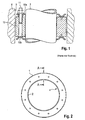
- the Fig. 1 shows a sectional view of a tube 7, which is sealed against a recess 9 of a masonry 8 by means of a pinch seal assembly.
- annular upper crimping flange 10a and an associated lower crimping flange 10b are provided, which can be braced against one another in the axial direction by means of screws.
- a plurality of sealing elements 12 are arranged, which are pinched by the axial tension and bulged radially. Due to the pressure occurring at the surface of the tube 7 and the recess 9 of the masonry 8, the desired sealing takes place.
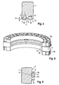
- a sealing element body 1 has a substantially rectangular cross-section (please refer Fig. 3 ).
- two annular beads 2 a, 2 b are formed on the radially inwardly facing side of the sealing element body 1, which run parallel to one another and whose side edges each pass over a radius 3 into the radially outer wall 13.
- At least one annular bead 2 which is formed on an outer surface 4 and the wall 3 of the sealing element body 1, it is possible to provide a sufficient seal with lower contact forces.
- the lower contact forces result from the fact that the material of the sealing element body 1 is pressed by the geometric configuration of the inventively provided, at least one annular bead 2 in the compression of the sealing element body 1, but not the material of the protruding annular bead 2 itself 2 pressed by the bulging material of the sealing element body 1 radially outwards and thus in the direction of the tube 7 and the recess 9 of the masonry 8.
- the sealing area which is formed by the annular bead 2, deformed by the axial compression, but the radially behind the annular bead 2 lying material of the sealing element body 1.
- the material of the annular bead 2 is thus not pressed or deformed, but only pushed radially outwards or inwards. It is understood that after a corresponding contact with the masonry 8 and the pipe 7, a deformation of the material of the annular bead 2 takes place. However, this is secondary and not causally due to the deformation of the sealing element body 1 itself.
- the annular bead 2 is pressed or deformed only slightly by the axial compression, a much higher elasticity of the material of the entire sealing element results in the area of the annular bead 2 and thus a significantly better sealing effect.
- the annular bead 2 by choosing a suitable width 14 and a suitable height 15 (see Fig. 3 ) of the annular bead 2 possible to increase the sealing surface, since the annular bead according to the invention not only linearly applied, but over its entire radial outer surface or inner surface.
- the transition to the elevations formed by the annular bead 2 is preferably formed by means of radii 3. These radii can be, for example, 0.5 to 5 mm.
- the width 14 of the annular bead 2 can be 10% to 60% in relation to the total width (axial extent) of the sealing element body 1.
- the sealing surface would reduce too much, while at a greater width, an axial compression of the annular bead 2 takes place, which in turn would reduce their elasticity.
- the height 15 of the annular bead 2 is according to the invention preferably matched to the diameter of the tube 7, it is for example between 3% and 30% of the radial total width of the sealing element body 1. A lower height would do not bring the advantages of the invention in terms of elasticity, while at a greater height of the annular bead 2 there is a risk of kinking away.
- the total width of the sealing element depends on the gap to be sealed, it is for example between 10 mm and 50 mm.
- the outer contour of the annular surface 2 substantially flat, as in Fig. 3 is shown.
- the radial outer surface of the annular bead 2 with two rib-like or ring-like elevations 5a, 5b form, which are interconnected via a radius region 6. This results from the elevations 5a, 5b outer edges, which are more increased, ie, widened in the radial direction. Due to the axial strain of the sealing element body 1 results in the in Fig. 5 shown embodiment by the deformation occurring in the installed state, a flat, outer contact surface of the annular bead 2, since the radius region 6 between the rib-like elevations 5a and 5b is deformed accordingly.
- annular beads 2 analog Fig. 3
- the sealing element according to the invention Due to the lower forces occurring, the resulting lower creep of the material of the tube 7, but also by the lower relaxation of the material of the sealing element body 1, according to the invention, materials outside the group of elastomers can be used. It is thus possible to manufacture the sealing element according to the invention also from TPE (thermoplastic elastomers). This simplifies the manufacturing effort, since these materials are thermoplastically processable.
- TPE thermoplastic elastomers
- the sealing element according to the invention is suitable for a wide variety of diameters, preferably tubes 7, lines or the like in the range of 150 mm to 320 mm outer diameter are sealed by means of the sealing element according to the invention.
Landscapes
- Engineering & Computer Science (AREA)
- General Engineering & Computer Science (AREA)
- Mechanical Engineering (AREA)
- Gasket Seals (AREA)
- Sealing Material Composition (AREA)
Abstract
Description
Die Erfindung bezieht sich auf ein Dichtungselement gemäß den Merkmalen des Oberbegriffs des Anspruches 1.The invention relates to a sealing element according to the features of the preamble of
Im Einzelnen bezieht sich die Erfindung auf ein Dichtungselement mit einem im Wesentlichen ringförmigen Körper aus einem elastischen Material, welcher mittels verspannbarer Flanschringe in Axialrichtung quetschbar und damit deformierbar ist.In detail, the invention relates to a sealing element with a substantially annular body made of an elastic material, which is compressible by means of bracing flange rings in the axial direction and thus deformed.
Ein Dichtungselement der genannten Art wird verwendet, um eine im Wesentlichen kreisrunde Öffnung, beispielsweise in einer Wand gegenüber einem durchgeführten Rohr oder einem durchgeführten Kabel, einer Leitung oder einem Stab abzudichten. Typischerweise erfolgt die Abdichtung gegenüber einem Mauerwerk, es sind erfindungsgemäß jedoch auch andere Anwendungsfälle möglich.A sealing element of the type mentioned is used to seal a substantially circular opening, for example in a wall opposite a duct or a cable being carried, a duct or a rod. Typically, the seal is against a masonry, but there are other applications possible according to the invention.
Durch die axiale Verspannung und Quetschung erfolgt eine Verpressung des Dichtungselements in radialer Richtung. Hierdurch erfolgt die Dichtung.Due to the axial clamping and crushing a compression of the sealing element takes place in the radial direction. This causes the seal.
Eine Dichtungsvorrichtung der genannten Art ist beispielsweise aus der
Bei der Verwendung von Dichtringen mit einem im Wesentlichen rechteckigen Querschnitt, welche einzeln oder als Pakete bekannt sind, ergibt sich der Nachteil, dass sich der Dichtring oder das Dichtelement in radialer Richtung ausbaucht und mittig eine linienförmige Dichtfläche bildet. Die Ausbauchung erfolgt dabei radial nach innen und radial nach außen, so dass sowohl die Wandung der Ausnehmung, beispielsweise in einem Bauwerk oder einem größeren Rohr mit Druck beaufschlagt wird, als auch die Wandung des durchzuführenden Gegenstandes, beispielsweise des Rohrs, des Kabels, der Leitung oder des Stabes.When using sealing rings with a substantially rectangular cross-section, which are known individually or as packages, there is the disadvantage that the sealing ring or the sealing element bulges in the radial direction and forms a line-shaped sealing surface in the center. The bulge takes place radially inwardly and radially outwards, so that both the wall of the recess, for example, in a building or a larger pipe is pressurized, and the wall of the object to be performed, for example, the pipe, the cable, the line or the staff.
Durch die starke Verpressung, welche speziell im Bereich der Ausbauchung des Dichtelements auftritt, verliert das elastische Material des Dichtungselements seine elastischen Eigenschaften. Um zu einer zuverlässigen Dichtungswirkung zu gelangen und um eine sichere Abdichtung zu erreichen, muss die Quetschung damit zusätzlich erhöht werden.Due to the strong compression, which occurs especially in the region of the bulge of the sealing element, the elastic material of the sealing element loses its elastic properties. To contribute to a reliable sealing effect In order to achieve a secure seal, the pinch must be further increased.
Durch eine hohe Flächenpressung entlang der im Wesentlichen linienförmigen Dichtfläche, welche in einigen Fällen nur eine reine Dichtlinie ausbildet, werden jedoch auch in dem abzudichtenden Gegenstand (sowohl radial außenliegend als auch radial innenliegend) resultierende Spannungen erzeugt. Hieraus folgt, dass in nachteiliger Weise nicht nur das Dichtungsmaterial des Dichtungselements, sondern auch die durchgeführte, abzudichtende Leitung selbst sowie das Material der Ausnehmung relaxiert. Dies wirkt sich insbesondere bei Rohren oder isolierten Rohren besonders nachteilig aus, da deren Materialien unter hohen Belastungen kriechen, so dass über längere Zeiträume die Dichtwirkung entweder nachlässt oder verloren geht oder das abzudichtende, durchgeführte Rohr oder die Leitung selbst entsprechend deformiert werden.However, due to a high surface pressure along the substantially linear sealing surface, which in some cases forms only a pure sealing line, resulting stresses are also produced in the article to be sealed (both radially outward and radially inward). It follows that disadvantageously relaxes not only the sealing material of the sealing element, but also the performed, to be sealed line itself and the material of the recess. This has a particularly disadvantageous effect on pipes or insulated pipes, since their materials creep under high loads, so that over longer periods of time the sealing effect either subsides or is lost or the pipe to be sealed or the pipe itself is deformed accordingly.
Dieser Effekt tritt insbesondere bei durchgeführten Rohren, insbesondere bei Kunststoffrohren auf, während sich die nachteiligen Effekte bei den abzudichtenden Ausnehmungen, beispielsweise im Mauerwerk, Beton, metallischen Außenrohren oder Ähnlichem, nicht in so starkem Maße auswirken.This effect occurs in particular in pipes performed, especially in plastic pipes, while the adverse effects in the sealed recesses, such as masonry, concrete, metallic outer tubes or the like, do not affect so much.
Die
Der Erfindung liegt die Aufgabe zugrunde, ein Dichtungselement der eingangs genannten Art zu schaffen, welches unter Vermeidung der Nachteile des Standes der Technik auch über einen langen Zeitraum hinweg eine gute Dichtwirkung gewährleistet.The invention has for its object to provide a sealing element of the type mentioned, which ensures a good sealing effect over a long period of time while avoiding the disadvantages of the prior art.
Erfindungsgemäß wird die Aufgabe durch die Merkmalskombination des Anspruchs 1 gelöst, die Unteransprüche zeigen weitere vorteilhafte Ausgestaltungen der Erfindung.According to the invention the object is achieved by the combination of features of
Erfindungsgemäß ist somit vorgesehen, dass das ringförmige Dichtelement an zumindest einer radialem Seite des im Wesentlichen rechteckigen Querschnitts mit zumindest einer zusätzlichen Ringwulst versehen ist.According to the invention it is thus provided that the annular sealing element is provided on at least one radial side of the substantially rectangular cross section with at least one additional annular bead.
Erfindungsgemäß kann die Ringwulst an der radial innenliegenden Seite des Dichtelements ausgebildet sein, es ist jedoch auch möglich, die Ringwulst (auch zusätzlich) an der radial außenliegenden Seite vorzusehen.According to the invention, the annular bead may be formed on the radially inner side of the sealing element, but it is also possible to provide the annular bead (also in addition) on the radially outer side.
Durch die erfindungsgemäß vorgesehene Ringwulst ändert sich somit die Geometrie des ringförmigen Dichtungselements, so dass eine bessere Abdichtung zu einer Leitung, einem Rohr oder Ähnlichem sowie auch zur Wandung einer Ausnehmung erfolgt.Thus, by the annular bead provided according to the invention, the geometry of the annular sealing element changes, so that a better sealing to a line, a pipe or the like as well as to the wall of a recess takes place.
In besonders günstiger Ausgestaltung der Erfindung ist vorgesehen, dass die Ringwulst einstückig mit dem Dichtungselement ausgebildet ist. Vorzugsweise ist sie aus dem gleichen Material wie das Dichtungselement gebildet, es ist jedoch auch möglich, unterschiedliche Materialien zu verwenden, die beispielsweise durch ein Insertverfahren in der Spritzgusstechnik oder durch andere Herstellungsverfahren zu einem einstückigen Dichtungselement verbunden werden.In a particularly favorable embodiment of the invention it is provided that the annular bead is formed integrally with the sealing element. Preferably, it is formed of the same material as the sealing member, but it is also possible to use different materials, which are joined, for example, by an injection molding technique or by other manufacturing methods to a one-piece sealing element.
In einer besonders vorteilhaften Ausgestaltung der Erfindung ist vorgesehen, dass zwei zueinander parallele Ringwülste an der radialen Wandung des Dichtungselementes ausgebildet sind. Hierdurch ergibt sich eine verbesserte Deformation und Verpressung, welche eine verbesserte Dichtwirkung zur Folge hat.In a particularly advantageous embodiment of the invention it is provided that two mutually parallel annular beads are formed on the radial wall of the sealing element. This results in an improved deformation and compression, which has an improved sealing effect.
Die geometrische Ausgestaltung der Ringwulst kann den unterschiedlichen Anwendungsbedingungen, den zu verwendenden Materialien sowie den Dimensionierungen angepasst werden. Es kann günstig sein, die Seitenflanken der Ringwulst mit einem Radius zu versehen. Die radial äußere Außenfläche der Ringwulst selbst kann entweder eben oder konturiert ausgebildet sein.The geometric configuration of the annular bead can be adapted to the different conditions of use, the materials to be used and the dimensions. It may be convenient to provide the side edges of the annular bead with a radius. The radially outer surface of the annular bead itself may be formed either flat or contoured.
Erfindungsgemäß ist vorgesehen, dass die einzelne Ringwulst an ihrer radialen Außenfläche mit zwei ringförmigen Erhebungen versehen ist, die über Radienbereiche miteinander verbunden sind.According to the invention it is provided that the individual annular bead is provided on its radial outer surface with two annular elevations, which are connected to each other via radii regions.
Erfindungsgemäß ist somit eine Lösung geschaffen worden, bei welcher das Dichtungselement eine höhere Härte aufweisen kann und zugleich mit geringeren Anpresskräften zuverlässig abdichtet. Im Bereich der Dichtfläche (Ringwulst) ergibt sich aufgrund der höheren Freiheitsgrade eine niedrigere Verpressung, welche die Beibehaltung der elastischen Eigenschaften des Materials des Dichtungselements bzw. der Ringwulst sichert.According to the invention, a solution has thus been created in which the sealing element can have a higher hardness and at the same time reliably seals with lower contact forces. In the area of the sealing surface (annular bead) results due to the higher degrees of freedom a lower compression, which ensures the maintenance of the elastic properties of the material of the sealing element or the annular bead.
Im Folgenden wird die Erfindung anhand von Ausführungsbeispielen in Verbindung mit der Zeichnung beschrieben. Dabei zeigt:
- Fig. 1
- eine Schnittansicht eines Quetschflansches gemäß dem Stand der Technik,
- Fig. 2
- eine axiale Draufsicht auf ein nicht erfindungsgemäßes Dichtungselement,
- Fig. 3
- eine Schnittansicht längs der Linie A-A von
Fig. 2 , - Fig.4
- eine perspektivische Ansicht des in
Fig. 2 und3 gezeigten Dichtungselements, und - Fig.
- 5 eine erfindungsgemäße Ausgestaltungsform in analoger Darstellung des Dichtungselement körpers 1.
- Fig. 1
- a sectional view of a pinch flange according to the prior art,
- Fig. 2
- an axial plan view of a non-inventive sealing element,
- Fig. 3
- a sectional view taken along the line AA of
Fig. 2 . - Figure 4
- a perspective view of the in
Fig. 2 and3 shown sealing element, and - FIG.
- 5 shows an embodiment according to the invention in an analogous representation of the sealing
element body 1.
Die
Hierzu sind ein ringförmiger oberer Quetschflansch 10a sowie ein zugeordneter unterer Quetschflansch 10b vorgesehen, welche mittels Schrauben gegeneinander in Axialrichtung verspannbar sind. Zwischen den Quetschflanschen 10 sind mehrere Dichtungselemente 12 angeordnet, welche durch die axiale Verspannung verquetscht und radial ausgebaucht werden. Durch den hierbei auftretenden Druck an der Oberfläche des Rohres 7 sowie der Ausnehmung 9 des Mauerwerkes 8 erfolgt die gewünschte Abdichtung.For this purpose, an annular
Die
Durch die erfindungsgemäß vorgesehene, zumindest eine Ringwulst 2, welche an einer Außenfläche 4 bzw. deren Wandung 3 des Dichtelementkörpers 1 ausgebildet ist, ist es möglich, mit geringeren Anpresskräften eine ausreichende Abdichtung vorzusehen. Die geringeren Anpresskräfte ergeben sich dadurch, dass durch die geometrische Ausgestaltung der erfindungsgemäß vorgesehenen, zumindest einen Ringwulst 2 bei der Verpressung des Dichtelementkörpers 1 im Wesentlichen das Material des Dichtelementkörpers 1 verpresst wird, nicht jedoch das Material der vorstehenden Ringwulst 2 selbst. Dabei wird die Ringwulst 2 durch das sich ausbauchende Material des Dichtelementkörpers 1 radial nach außen und somit in Richtung auf das Rohr 7 bzw. die Ausnehmung 9 des Mauerwerks 8 gepresst.By inventively provided, at least one
Erfindungsgemäß wird somit nicht der dichtende Bereich, der durch die Ringwulst 2 gebildet wird, durch die axiale Verpressung verformt, sondern das radial hinter der Ringwulst 2 liegende Material des Dichtungselementkörpers 1. Das Material der Ringwulst 2 wird somit selbst nicht verpresst oder deformiert, sondern lediglich radial nach außen bzw. nach innen geschoben. Es versteht sich, dass nach einem entsprechenden Kontakt mit dem Mauerwerk 8 bzw. dem Rohr 7 auch eine Verformung des Materials der Ringwulst 2 erfolgt. Dies ist jedoch sekundär und nicht ursächlich bedingt durch die Verformung des Dichtelementkörpers 1 selbst.According to the invention is thus not the sealing area, which is formed by the
Da erfindungsgemäß die Ringwulst 2 durch das axiale Verpressen selbst nur gering verpresst oder deformiert wird, ergibt sich im Bereich der Ringwulst 2 eine weitaus höhere Elastizität des Materials des gesamten Dichtungselements und damit eine wesentlich bessere Dichtwirkung.Since, according to the invention, the
Durch diese bessere Dichtwirkung ist es möglich, die Anpresskraft, welche in radialer Richtung auf das Rohr 7 bzw. die Ausnehmung 9 des Mauerwerks 8 wirkt, zu senken. Dies wiederum führt zu einem verbesserten Kriechverhalten sowohl des Materials des Rohrs 7 als auch der Ausnehmung 9 des Mauerwerks 8 (es ist an dieser Stelle nochmals zu betonen, dass die Bezugnahme auf das Rohr 7 und die Ausnehmung 9 des Mauerwerks 8 nur beispielhaft ist, erfindungsgemäß ist jede denkbare Paarung von Materialien oder Bauelementen möglich).Due to this better sealing effect, it is possible to lower the contact force which acts in the radial direction on the
Durch den geringeren Anpressdruck werden somit mechanische Deformationen des Rohrs 7 vermieden. Dies ist insbesondere bei dünnwandigen Rohren oder Leitungen oder bei Rohren oder Leitungen, welche mit einer Isolierschicht versehen sind, von besonderem Vorteil, da deren Steifigkeit üblicherweise geringer ist. Erfindungsgemäß wird somit eine Aufbringung zu hoher Anpresskräfte und eine nachfolgende Einschnürung oder Deformation vermieden, welche zu einem Nachlassen der Dichtfunktion führen würde.Due to the lower contact pressure thus mechanical deformation of the
Erfindungsgemäß ist es durch Wahl einer geeigneten Breite 14 sowie einer geeigneten Höhe 15 (siehe
Durch die Verwendung mehrerer, zueinander paralleler Ringwülste (siehe
Der Übergang zu den durch die Ringwulst 2 gebildeten Erhebungen ist bevorzugterweise mittels Radien 3 ausgebildet. Diese Radien können beispielsweise 0,5 bis 5 mm betragen.The transition to the elevations formed by the
Die Breite 14 der Ringwulst 2 kann erfindungsgemäß im Verhältnis zur Gesamtbreite (axiale Erstreckung) des Dichtelementkörpers 1 10% bis 60% sein. Bei kleineren Breiten 14 würde sich die Dichtfläche zu stark verringern, während bei einer größeren Breite eine axiale Verpressung der Ringwulst 2 erfolgt, welche deren Elastizität wiederum herabsetzen würde.According to the invention, the
Die Höhe 15 der Ringwulst 2 ist erfindungsgemäß bevorzugt auf den Durchmesser des Rohres 7 abgestimmt, sie beträgt beispielsweise zwischen 3% und 30% der radialen Gesamtbreite des Dichtungselementkörpers 1. Eine geringere Höhe würde nicht die erfindungsgemäßen Vorteile hinsichtlich der Elastizität bringen, während bei einer größeren Höhe der Ringwulst 2 die Gefahr eines Wegknickens besteht.The
Erfindungsgemäß ist die Gesamtbreite des Dichtungselements (axiale Erstreckung) abhängig von dem abzudichtenden Spalt, sie beträgt beispielsweise zwischen 10 mm und 50 mm.According to the invention the total width of the sealing element (axial extent) depends on the gap to be sealed, it is for example between 10 mm and 50 mm.
Es ist möglich, die äußere Kontur der Ringfläche 2 im Wesentlichen eben auszubilden, so wie dies in
Erfindungsgemäß ist es auch möglich, bei Verwendung mehrerer Ringwülste 2 (analog
Durch die erfindungsgemäß vorgesehene geringere Deformation des Materials der Ringwulst 2, verglichen mit der Deformation des Materials des Dichtelementkörpers 1, ergeben sich wesentlich bessere elastische Eigenschaften des Materials der Ringwulst 2. Dies resultiert in einer höheren Elastizität, welche wiederum zu geringeren erforderlichen Anpresskräften führt. Somit ist es erfindungsgemäß insbesondere möglich, alternativ zu einem EPDM-Material (Ethylen-Propylen-DienKautschuk) auch andere Materialien mit größerer Härte zu verwenden. So ist es erfindungsgemäß beispielsweise möglich, NBR (Acrylnitril-Butadien-Kautschuk) einzusetzen. Hierdurch ist es möglich, auch gasdichte Durchführungen zu realisieren. Es ist erfindungsgemäß auch möglich, Naturkautschuk oder andere Kunststoffe aus der Gruppe der Elastomere zu verwenden. Während im Stand der Technik die notwendige Härte des Elastomers bei 30 bis 35 ShoreA bei Anwendung für isolierte Rohre und Rohre mit hoher Kriechneigung liegt, können erfindungsgemäß auch Werkstoffe mit einer ShoreA-Härte von 40 und größer verwendet werden.By inventively provided lower deformation of the material of the
Durch die geringeren auftretenden Kräfte, durch die daraus resultierende geringere Kriechneigung des Materials des Rohrs 7, aber auch durch die geringere Relaxation des Materials des Dichtungselementkörpers 1, können erfindungsgemäß auch Materialien außerhalb der Gruppe der Elastomere verwendet werden. So ist es möglich, das erfindungsgemäße Dichtungselement auch aus TPE (thermoplastische Elastomere) zu fertigen. Hierdurch vereinfacht sich der Herstellungsaufwand, da diese Materialien thermoplastisch verarbeitbar sind.Due to the lower forces occurring, the resulting lower creep of the material of the
Erfindungsgemäß ist es somit möglich, Rohre 7, Leitungen, Kabel oder Ähnliches mit geringerer Steifigkeit dauerhaft abzudichten und längere Standzeiten, bedingt durch die bessere Elastizität im Dichtungsbereich der Ringwülste 2 durch die auftretende geringere Relaxation zu erzielen.According to the invention it is thus possible to permanently seal
Das erfindungsgemäße Dichtungselement ist für unterschiedlichste Durchmesser geeignet, bevorzugterweise werden Rohre 7, Leitungen oder Ähnliches im Bereich von 150 mm bis 320 mm Außendurchmesser mittels des erfindungsgemäßen Dichtungselements abgedichtet.The sealing element according to the invention is suitable for a wide variety of diameters, preferably
- 11
- DichtungselementkörperSeal member body
- 2, 2a, 2b2, 2a, 2b
- Ringwulsttorus
- 33
- Radiusradius
- 44
- Außenflächeouter surface
- 5a, 5b5a, 5b
- Erhebungsurvey
- 66
- Radienbereichradius range
- 77
- Rohrpipe
- 88th
- Mauerwerkmasonry
- 99
- Ausnehmungrecess
- 1010
- Quetschflansch/FlanschringQuetschflansch / flange
- 1111
- Schraubescrew
- 1212
- Dichtungselementsealing element
- 1313
- Wandungwall
- 1414
- Breitewidth
- 1515
- Höheheight
Claims (12)
- A sealing member comprising a substantially annular body (1) made of an elastic material, the body (1) being provided with a substantially rectangular cross-section and being deformable in the axial direction of the sealing member, wherein at least one annular bead (2) is arranged at the body (1) on at least a radial side thereof, characterized in that the radial outer surface (4) of the annular bead (2) is shaped as a contour and comprises two annular projections (5a, 5b) which are connected to each other through radial portions (6).
- The sealing member of claim 1, characterized in that the body (1) and the annular bead (2) are integrally connected.
- The sealing member of claim 1 or 2, characterized in that the body (1) and the annular bead (2) are made of the same material.
- The sealing member of claim 1 or 2, characterized in that the body (1) and the annular bead (2) are made of different materials.
- The sealing member of one of claims 1 to 4, characterized in that two parallel annular beads (2a, 2b) are arranged on the at least one side of the body (1).
- The sealing member of one of claims 1 to 5, characterized in that at least a lateral flank of the annular bead (2) is provided with a radius (3).
- The sealing member of one of claims 1 to 6, characterized in that same is made of an ethylene-propylene-dien-rubber (EPDM) material.
- The sealing member of one of claims 1 to 7, characterized in that same is made of an acrylnitrile-butadien-rubber (NBR) material.
- The sealing member of one of claims 1 to 7, characterized in that same is made of an elastomer material.
- The sealing member of one of claims 1 to 7, characterized in that same is made of an natural rubber material.
- The sealing member of one of claims 1 to 7, characterized in that same is made of an thermoplast elastomer material.
- A transverse flange comprising at least two flange rings (10) which can be tensioned against each other in the axial direction as well as at least one sealing member arranged between the flange rings (10), which sealing member is formed according to one of claims 1 to 11.
Applications Claiming Priority (1)
| Application Number | Priority Date | Filing Date | Title |
|---|---|---|---|
| DE102008058743A DE102008058743A1 (en) | 2008-11-24 | 2008-11-24 | sealing element |
Publications (2)
| Publication Number | Publication Date |
|---|---|
| EP2189686A1 EP2189686A1 (en) | 2010-05-26 |
| EP2189686B1 true EP2189686B1 (en) | 2011-09-21 |
Family
ID=41697941
Family Applications (1)
| Application Number | Title | Priority Date | Filing Date |
|---|---|---|---|
| EP09012127A Active EP2189686B1 (en) | 2008-11-24 | 2009-09-23 | Seal element |
Country Status (4)
| Country | Link |
|---|---|
| EP (1) | EP2189686B1 (en) |
| AT (1) | ATE525600T1 (en) |
| DE (1) | DE102008058743A1 (en) |
| ES (1) | ES2372360T3 (en) |
Families Citing this family (1)
| Publication number | Priority date | Publication date | Assignee | Title |
|---|---|---|---|---|
| CN105423150B (en) * | 2016-01-11 | 2019-03-26 | 深圳市立洋光电子股份有限公司 | A kind of waterproof construction of LED module |
Family Cites Families (8)
| Publication number | Priority date | Publication date | Assignee | Title |
|---|---|---|---|---|
| SE465095B (en) * | 1988-07-07 | 1991-07-22 | Gambro Dialysatoren | SEALING INCLUDING A RING OF A FLEXIBLE MATERIAL INTENDED TO BE PRESSED BETWEEN TWO PARALLEL, PRELIMINALLY SMALL SEALING SURFACES |
| DE29618521U1 (en) * | 1996-10-24 | 1997-02-06 | Hermann-Heinz Burger Gas- und Wasserarmaturen GmbH, 59423 Unna | Press ring closure |
| US7407165B1 (en) * | 2000-04-04 | 2008-08-05 | Hutchinson Fts, Inc. | Composite sleeve for sealing a tubular coupling |
| DE10020493A1 (en) * | 2000-04-26 | 2001-11-08 | Dsi Rohrleitungsbau Zubehoer | Device for sealing an annular space delimited by an inner and an outer body |
| DE20200374U1 (en) | 2002-01-11 | 2003-05-22 | DOYMA GmbH & Co, 28876 Oyten | sealing device |
| US6957817B2 (en) * | 2002-10-29 | 2005-10-25 | Mar Don Corporation | Seal assembly and method of forming seal |
| US20060261560A1 (en) * | 2005-05-02 | 2006-11-23 | Radliff David R | Sealing assemblies and methods for sealing an elongate member |
| EP1837572A1 (en) * | 2006-03-20 | 2007-09-26 | Beele Engineering B.V. | System for sealing a space between an inner wall of a tubular opening and at least one tube or duct at least partly received in the opening |
-
2008
- 2008-11-24 DE DE102008058743A patent/DE102008058743A1/en not_active Withdrawn
-
2009
- 2009-09-23 ES ES09012127T patent/ES2372360T3/en active Active
- 2009-09-23 AT AT09012127T patent/ATE525600T1/en active
- 2009-09-23 EP EP09012127A patent/EP2189686B1/en active Active
Also Published As
| Publication number | Publication date |
|---|---|
| DE102008058743A1 (en) | 2010-06-02 |
| ES2372360T3 (en) | 2012-01-19 |
| ATE525600T1 (en) | 2011-10-15 |
| EP2189686A1 (en) | 2010-05-26 |
Similar Documents
| Publication | Publication Date | Title |
|---|---|---|
| EP2735779B1 (en) | Device for the sealed feedthrough of long moulded parts | |
| DE102010060981B3 (en) | Pipe flange used in e.g. chemical plant, has screws that are inserted into through-holes of plastic flange portions, to connect flange portions with counter-element under force application of sealing ring | |
| EP2376801B1 (en) | Air spring | |
| EP2793334A2 (en) | Cable connection with integral joint | |
| DE102010021834A1 (en) | Loose flange connector i.e. flare flange connector, has pipe sockets connected over sealing material, where sealing material is arranged in force shunt between sealing surfaces in inwardly displaced manner opposite to fastening unit | |
| DE2714963C3 (en) | Elastic pipe connector | |
| DE102008055511A1 (en) | Air spring for commercial vehicle such as towing vehicle or trailers, has rolling piston made up of plastic and bellow made up of elastomeric material, where bellow has fastening bead with bead core at its end facing rolling piston | |
| EP2189686B1 (en) | Seal element | |
| EP3361118A1 (en) | Air spring with a two-part plastic bead plate | |
| EP3978751B1 (en) | Composite membrane for membrane pumps | |
| EP2829781B1 (en) | Pressing body for compression seal and compression seal | |
| EP3153754B1 (en) | Compressible flange with mounting control | |
| EP1500853B1 (en) | Sealing with a variable internal diameter | |
| DE102009011363B3 (en) | Double side acting sealing ring for sealing sliding plate and wall of slide fitting, has frame arranged at external side of sealing body, which has extension formed by two parts, where frame is connected with extension | |
| EP0058211B1 (en) | Self-sealing washer | |
| EP0789823B1 (en) | Detachable connecting or sealing device for transmitting axial tensile forces or hydraulic pressure forces | |
| EP1136734A1 (en) | Seal, especially for flanged connections | |
| DE102012202908A1 (en) | Sealing device for sealing annular space of e.g. cable, has push plates and/or press flanges for applying pressing forces on sealing rings so as to cause axial compressing and radial expanding of sealing rings | |
| EP3464963A1 (en) | Groove ring seal and method for production thereof | |
| EP3642523B1 (en) | Sealing sleeve for a pipe clamp and pipe clamp having such a sealing sleeve | |
| EP3663624A1 (en) | Gasket | |
| EP1983629A1 (en) | Cable gland | |
| EP2982894B1 (en) | Tube clamp assembly | |
| EP2559929B1 (en) | Conduit lead through with test volume | |
| EP1715221B1 (en) | Fixing of the end part of a bellow to a connecting part |
Legal Events
| Date | Code | Title | Description |
|---|---|---|---|
| PUAI | Public reference made under article 153(3) epc to a published international application that has entered the european phase |
Free format text: ORIGINAL CODE: 0009012 |
|
| AK | Designated contracting states |
Kind code of ref document: A1 Designated state(s): AT BE BG CH CY CZ DE DK EE ES FI FR GB GR HR HU IE IS IT LI LT LU LV MC MK MT NL NO PL PT RO SE SI SK SM TR |
|
| AX | Request for extension of the european patent |
Extension state: AL BA RS |
|
| 17P | Request for examination filed |
Effective date: 20100622 |
|
| GRAP | Despatch of communication of intention to grant a patent |
Free format text: ORIGINAL CODE: EPIDOSNIGR1 |
|
| GRAS | Grant fee paid |
Free format text: ORIGINAL CODE: EPIDOSNIGR3 |
|
| GRAA | (expected) grant |
Free format text: ORIGINAL CODE: 0009210 |
|
| AK | Designated contracting states |
Kind code of ref document: B1 Designated state(s): AT BE BG CH CY CZ DE DK EE ES FI FR GB GR HR HU IE IS IT LI LT LU LV MC MK MT NL NO PL PT RO SE SI SK SM TR |
|
| REG | Reference to a national code |
Ref country code: GB Ref legal event code: FG4D Free format text: NOT ENGLISH |
|
| REG | Reference to a national code |
Ref country code: CH Ref legal event code: EP |
|
| REG | Reference to a national code |
Ref country code: IE Ref legal event code: FG4D Free format text: LANGUAGE OF EP DOCUMENT: GERMAN |
|
| REG | Reference to a national code |
Ref country code: CH Ref legal event code: NV Representative=s name: KELLER & PARTNER PATENTANWAELTE AG WINTERTHUR |
|
| REG | Reference to a national code |
Ref country code: DE Ref legal event code: R096 Ref document number: 502009001364 Country of ref document: DE Effective date: 20111208 |
|
| REG | Reference to a national code |
Ref country code: NL Ref legal event code: VDEP Effective date: 20110921 |
|
| REG | Reference to a national code |
Ref country code: ES Ref legal event code: FG2A Ref document number: 2372360 Country of ref document: ES Kind code of ref document: T3 Effective date: 20120119 |
|
| PG25 | Lapsed in a contracting state [announced via postgrant information from national office to epo] |
Ref country code: NO Free format text: LAPSE BECAUSE OF FAILURE TO SUBMIT A TRANSLATION OF THE DESCRIPTION OR TO PAY THE FEE WITHIN THE PRESCRIBED TIME-LIMIT Effective date: 20111221 Ref country code: HR Free format text: LAPSE BECAUSE OF FAILURE TO SUBMIT A TRANSLATION OF THE DESCRIPTION OR TO PAY THE FEE WITHIN THE PRESCRIBED TIME-LIMIT Effective date: 20110921 Ref country code: LT Free format text: LAPSE BECAUSE OF FAILURE TO SUBMIT A TRANSLATION OF THE DESCRIPTION OR TO PAY THE FEE WITHIN THE PRESCRIBED TIME-LIMIT Effective date: 20110921 Ref country code: FI Free format text: LAPSE BECAUSE OF FAILURE TO SUBMIT A TRANSLATION OF THE DESCRIPTION OR TO PAY THE FEE WITHIN THE PRESCRIBED TIME-LIMIT Effective date: 20110921 Ref country code: SE Free format text: LAPSE BECAUSE OF FAILURE TO SUBMIT A TRANSLATION OF THE DESCRIPTION OR TO PAY THE FEE WITHIN THE PRESCRIBED TIME-LIMIT Effective date: 20110921 |
|
| LTIE | Lt: invalidation of european patent or patent extension |
Effective date: 20110921 |
|
| PG25 | Lapsed in a contracting state [announced via postgrant information from national office to epo] |
Ref country code: LV Free format text: LAPSE BECAUSE OF FAILURE TO SUBMIT A TRANSLATION OF THE DESCRIPTION OR TO PAY THE FEE WITHIN THE PRESCRIBED TIME-LIMIT Effective date: 20110921 Ref country code: CY Free format text: LAPSE BECAUSE OF FAILURE TO SUBMIT A TRANSLATION OF THE DESCRIPTION OR TO PAY THE FEE WITHIN THE PRESCRIBED TIME-LIMIT Effective date: 20110921 Ref country code: GR Free format text: LAPSE BECAUSE OF FAILURE TO SUBMIT A TRANSLATION OF THE DESCRIPTION OR TO PAY THE FEE WITHIN THE PRESCRIBED TIME-LIMIT Effective date: 20111222 Ref country code: SI Free format text: LAPSE BECAUSE OF FAILURE TO SUBMIT A TRANSLATION OF THE DESCRIPTION OR TO PAY THE FEE WITHIN THE PRESCRIBED TIME-LIMIT Effective date: 20110921 |
|
| BERE | Be: lapsed |
Owner name: POLOPLAST GMBH & CO. KG Effective date: 20110930 |
|
| REG | Reference to a national code |
Ref country code: IE Ref legal event code: FD4D |
|
| PG25 | Lapsed in a contracting state [announced via postgrant information from national office to epo] |
Ref country code: IS Free format text: LAPSE BECAUSE OF FAILURE TO SUBMIT A TRANSLATION OF THE DESCRIPTION OR TO PAY THE FEE WITHIN THE PRESCRIBED TIME-LIMIT Effective date: 20120121 Ref country code: CZ Free format text: LAPSE BECAUSE OF FAILURE TO SUBMIT A TRANSLATION OF THE DESCRIPTION OR TO PAY THE FEE WITHIN THE PRESCRIBED TIME-LIMIT Effective date: 20110921 Ref country code: SK Free format text: LAPSE BECAUSE OF FAILURE TO SUBMIT A TRANSLATION OF THE DESCRIPTION OR TO PAY THE FEE WITHIN THE PRESCRIBED TIME-LIMIT Effective date: 20110921 Ref country code: IE Free format text: LAPSE BECAUSE OF FAILURE TO SUBMIT A TRANSLATION OF THE DESCRIPTION OR TO PAY THE FEE WITHIN THE PRESCRIBED TIME-LIMIT Effective date: 20110921 Ref country code: MC Free format text: LAPSE BECAUSE OF NON-PAYMENT OF DUE FEES Effective date: 20110930 |
|
| PG25 | Lapsed in a contracting state [announced via postgrant information from national office to epo] |
Ref country code: PL Free format text: LAPSE BECAUSE OF FAILURE TO SUBMIT A TRANSLATION OF THE DESCRIPTION OR TO PAY THE FEE WITHIN THE PRESCRIBED TIME-LIMIT Effective date: 20110921 Ref country code: PT Free format text: LAPSE BECAUSE OF FAILURE TO SUBMIT A TRANSLATION OF THE DESCRIPTION OR TO PAY THE FEE WITHIN THE PRESCRIBED TIME-LIMIT Effective date: 20120123 Ref country code: EE Free format text: LAPSE BECAUSE OF FAILURE TO SUBMIT A TRANSLATION OF THE DESCRIPTION OR TO PAY THE FEE WITHIN THE PRESCRIBED TIME-LIMIT Effective date: 20110921 Ref country code: RO Free format text: LAPSE BECAUSE OF FAILURE TO SUBMIT A TRANSLATION OF THE DESCRIPTION OR TO PAY THE FEE WITHIN THE PRESCRIBED TIME-LIMIT Effective date: 20110921 Ref country code: NL Free format text: LAPSE BECAUSE OF FAILURE TO SUBMIT A TRANSLATION OF THE DESCRIPTION OR TO PAY THE FEE WITHIN THE PRESCRIBED TIME-LIMIT Effective date: 20110921 |
|
| PG25 | Lapsed in a contracting state [announced via postgrant information from national office to epo] |
Ref country code: BE Free format text: LAPSE BECAUSE OF NON-PAYMENT OF DUE FEES Effective date: 20110930 |
|
| PLBE | No opposition filed within time limit |
Free format text: ORIGINAL CODE: 0009261 |
|
| STAA | Information on the status of an ep patent application or granted ep patent |
Free format text: STATUS: NO OPPOSITION FILED WITHIN TIME LIMIT |
|
| PG25 | Lapsed in a contracting state [announced via postgrant information from national office to epo] |
Ref country code: DK Free format text: LAPSE BECAUSE OF FAILURE TO SUBMIT A TRANSLATION OF THE DESCRIPTION OR TO PAY THE FEE WITHIN THE PRESCRIBED TIME-LIMIT Effective date: 20110921 |
|
| 26N | No opposition filed |
Effective date: 20120622 |
|
| REG | Reference to a national code |
Ref country code: DE Ref legal event code: R097 Ref document number: 502009001364 Country of ref document: DE Effective date: 20120622 |
|
| PG25 | Lapsed in a contracting state [announced via postgrant information from national office to epo] |
Ref country code: MT Free format text: LAPSE BECAUSE OF FAILURE TO SUBMIT A TRANSLATION OF THE DESCRIPTION OR TO PAY THE FEE WITHIN THE PRESCRIBED TIME-LIMIT Effective date: 20110921 Ref country code: MK Free format text: LAPSE BECAUSE OF FAILURE TO SUBMIT A TRANSLATION OF THE DESCRIPTION OR TO PAY THE FEE WITHIN THE PRESCRIBED TIME-LIMIT Effective date: 20110921 |
|
| PG25 | Lapsed in a contracting state [announced via postgrant information from national office to epo] |
Ref country code: SM Free format text: LAPSE BECAUSE OF FAILURE TO SUBMIT A TRANSLATION OF THE DESCRIPTION OR TO PAY THE FEE WITHIN THE PRESCRIBED TIME-LIMIT Effective date: 20110921 |
|
| PG25 | Lapsed in a contracting state [announced via postgrant information from national office to epo] |
Ref country code: LU Free format text: LAPSE BECAUSE OF NON-PAYMENT OF DUE FEES Effective date: 20110923 |
|
| PG25 | Lapsed in a contracting state [announced via postgrant information from national office to epo] |
Ref country code: BG Free format text: LAPSE BECAUSE OF FAILURE TO SUBMIT A TRANSLATION OF THE DESCRIPTION OR TO PAY THE FEE WITHIN THE PRESCRIBED TIME-LIMIT Effective date: 20111221 |
|
| PG25 | Lapsed in a contracting state [announced via postgrant information from national office to epo] |
Ref country code: TR Free format text: LAPSE BECAUSE OF FAILURE TO SUBMIT A TRANSLATION OF THE DESCRIPTION OR TO PAY THE FEE WITHIN THE PRESCRIBED TIME-LIMIT Effective date: 20110921 |
|
| PG25 | Lapsed in a contracting state [announced via postgrant information from national office to epo] |
Ref country code: HU Free format text: LAPSE BECAUSE OF FAILURE TO SUBMIT A TRANSLATION OF THE DESCRIPTION OR TO PAY THE FEE WITHIN THE PRESCRIBED TIME-LIMIT Effective date: 20110921 |
|
| GBPC | Gb: european patent ceased through non-payment of renewal fee |
Effective date: 20130923 |
|
| PG25 | Lapsed in a contracting state [announced via postgrant information from national office to epo] |
Ref country code: GB Free format text: LAPSE BECAUSE OF NON-PAYMENT OF DUE FEES Effective date: 20130923 |
|
| REG | Reference to a national code |
Ref country code: CH Ref legal event code: PCAR Free format text: NEW ADDRESS: EIGERSTRASSE 2 POSTFACH, 3000 BERN 14 (CH) |
|
| REG | Reference to a national code |
Ref country code: FR Ref legal event code: PLFP Year of fee payment: 8 |
|
| REG | Reference to a national code |
Ref country code: FR Ref legal event code: PLFP Year of fee payment: 9 |
|
| REG | Reference to a national code |
Ref country code: FR Ref legal event code: PLFP Year of fee payment: 10 |
|
| REG | Reference to a national code |
Ref country code: CH Ref legal event code: PFA Owner name: POLOPLAST GMBH AND CO. KG, AT Free format text: FORMER OWNER: POLOPLAST GMBH AND CO. KG, AT |
|
| PGFP | Annual fee paid to national office [announced via postgrant information from national office to epo] |
Ref country code: AT Payment date: 20230915 Year of fee payment: 15 |
|
| PGFP | Annual fee paid to national office [announced via postgrant information from national office to epo] |
Ref country code: ES Payment date: 20231019 Year of fee payment: 15 |
|
| PGFP | Annual fee paid to national office [announced via postgrant information from national office to epo] |
Ref country code: IT Payment date: 20230929 Year of fee payment: 15 Ref country code: CH Payment date: 20231002 Year of fee payment: 15 |
|
| PGFP | Annual fee paid to national office [announced via postgrant information from national office to epo] |
Ref country code: DE Payment date: 20240925 Year of fee payment: 16 |
|
| PGFP | Annual fee paid to national office [announced via postgrant information from national office to epo] |
Ref country code: FR Payment date: 20240924 Year of fee payment: 16 |
|
| PGFP | Annual fee paid to national office [announced via postgrant information from national office to epo] |
Ref country code: AT Payment date: 20240918 Year of fee payment: 16 |