EP2189675B1 - Shaft coupling - Google Patents
Shaft coupling Download PDFInfo
- Publication number
- EP2189675B1 EP2189675B1 EP08020461A EP08020461A EP2189675B1 EP 2189675 B1 EP2189675 B1 EP 2189675B1 EP 08020461 A EP08020461 A EP 08020461A EP 08020461 A EP08020461 A EP 08020461A EP 2189675 B1 EP2189675 B1 EP 2189675B1
- Authority
- EP
- European Patent Office
- Prior art keywords
- shaft
- end piece
- shaft end
- shaped support
- transducer
- Prior art date
- Legal status (The legal status is an assumption and is not a legal conclusion. Google has not performed a legal analysis and makes no representation as to the accuracy of the status listed.)
- Expired - Fee Related
Links
Images

Classifications
-
- F—MECHANICAL ENGINEERING; LIGHTING; HEATING; WEAPONS; BLASTING
- F16—ENGINEERING ELEMENTS AND UNITS; GENERAL MEASURES FOR PRODUCING AND MAINTAINING EFFECTIVE FUNCTIONING OF MACHINES OR INSTALLATIONS; THERMAL INSULATION IN GENERAL
- F16D—COUPLINGS FOR TRANSMITTING ROTATION; CLUTCHES; BRAKES
- F16D3/00—Yielding couplings, i.e. with means permitting movement between the connected parts during the drive
- F16D3/02—Yielding couplings, i.e. with means permitting movement between the connected parts during the drive adapted to specific functions
- F16D3/04—Yielding couplings, i.e. with means permitting movement between the connected parts during the drive adapted to specific functions specially adapted to allow radial displacement, e.g. Oldham couplings
Definitions
- This symmetrical arrangement can be a uniform force distribution.
- a simplified production of the torque transmission element is made possible by the symmetrical arrangement of the web-shaped support elements or the pair of web-shaped support elements.
- this can be done by a simple and symmetrical design of the encoder shaft end. In this way, the coupling or mounting of the encoder shaft end piece can be done with the torque transmission element easier.
- third longitudinal axes of a third pair of web-shaped supporting elements which serve to make contact with the machine shaft end piece, are substantially parallel to one another and preferably lie on a common straight line.
- the frame element is designed as a ring.
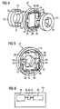
- FIG. 5 shows the embodiment of a shaft coupling 20 according to the invention FIG. 4 with the torque transmitting element 27 and the recorded machine shaft end 12 in the coupled state.
- the FIG. 5 serves for the more precise visualization of the under FIG. 4
- the coupling of the torque transmitting element 27 is shown with the Maschinenwellenend Published 12 explicitly, a coupling of the encoder shaft end piece 17 with the torque transmitting element 27 is to be formed accordingly.
- the torsional force vector 24 caused by a torsional moment 26 at the contact point, between the claw-like element 13, the machine shaft end portion 12, and the third and fourth pairs 29, 30 of web-shaped support elements 28 parallel to the longitudinal axis of the third and fourth pair 29, 30 web-shaped support elements 28 acts.
Description
Die Erfindung betrifft eine Wellenkupplung zur Ankopplung eines Gebers, der eine Geberwelle aufweist, an eine elektrische Maschine, insbesondere einen Elektromotor, die eine Maschinenwelle aufweist.The invention relates to a shaft coupling for coupling a transmitter, which has a sensor shaft, to an electric machine, in particular an electric motor having a machine shaft.
Beim Einsatz von elektrischen Maschinen mit rotierenden Wellen ist es oft erwünscht eine Drehzahl einer Welle oder eine Lage eines Rotors zu erfassen. In der Regel sind Motoren daher mit einem Winkelmesssystem ausgestattet. Mit diesem Winkelmesssystem kann ein Umrichter eine Winkellage eines Motorläufers zum Motorständer bestimmen und/oder einen Drehzahlistwert für eine Drehzahlregelung ermitteln.When using electric machines with rotating shafts, it is often desirable to detect a rotational speed of a shaft or a position of a rotor. As a rule, motors are therefore equipped with an angle measuring system. With this angle measuring system, a converter can determine an angular position of a motor rotor to the motor stator and / or determine a speed actual value for a speed control.
Die mechanische Kopplung eines Winkelgebers an den Motor erfolgt z.B. mit einer Wellenkupplung oder einer Drehmomentstütze. Diese Kupplungen müssen auf der einen Seite möglichst drehsteif sein, d.h. eine hohe Torsionskonstante bzw. ein hohes Torsionsmoment aufweisen, auf der anderen Seite jedoch möglichst geringe Querkräfte weitergeben, da ansonsten die Lager der Maschinenwelle und insbesondere die Lager der Geberwelle belastet werden und es dort zu einem Verschleiß kommt. Querkräfte auf den Lagern werden beispielsweise durch mechanischen Versatz der zu kuppelnden Achsen erzeugt. Hierbei wird zwischen Radialversatz und Winkelversatz unterschieden.The mechanical coupling of an angle sensor to the motor takes place e.g. with a shaft coupling or torque arm. These couplings must be as torsionally stiff as possible on one side, i. have a high torsional constant or a high torsional moment, on the other hand, however, pass on the lowest possible lateral forces, otherwise the bearings of the machine shaft and in particular the bearings of the encoder shaft are loaded and there is a wear. Transverse forces on the bearings are generated, for example, by mechanical displacement of the axes to be coupled. Here, a distinction is made between radial offset and angular offset.
Bei den heute verwendeten Wellenkupplungen werden verschiedene Kupplungsarten verwendet. All diesen Kupplungsprinzipen ist gemein, dass bei einer Optimierung der Wellenkupplung auf ein hohes Torsionsmoment bzw. eine höhere Torsionskonstante immer auch die unerwünschte Übertragung der Querkräfte bei mechanischem Versatz der Symmetrieachsen größer wird.The shaft couplings used today use different types of couplings. All these coupling principles have in common that with an optimization of the shaft coupling to a high torsional moment or a higher torsional constant always the unwanted transmission of lateral forces at mechanical displacement of the axes of symmetry is greater.
Nach dem Stand der Technik werden die Wellenkupplungen in der Regel so ausgelegt, dass die Torsionskonstante die für die Anwendung notwendige Größe erreicht und die Auswirkungen der sich dabei einstellenden hohen Querkräfte bzw. Biegemomente in Kauf genommen werden.According to the prior art, the shaft couplings are usually designed so that the torsional constant reaches the size necessary for the application and the effects of the resulting high transverse forces or bending moments are accepted.
Aus der
Bei der
Aus der
Aus der
Der Erfindung liegt die Aufgabe zugrunde, eine Wellenkupplung zu schaffen, die einen möglichst verschleißarmen Betrieb gewährt.The invention has for its object to provide a shaft coupling, which grants the lowest possible wear operation.
Die Lösung der gestellten Aufgabe gelingt durch eine Wellenkupplung zur Ankopplung eines Gebers, der eine Geberwelle aufweist, an eine elektrische Maschine, die eine Maschinenwelle aufweist, wobei die Wellenkupplung umfasst:
- ein mit der Geberwelle koppelbares Geberwellenendstück,
- ein mit der Maschinenwelle koppelbares Maschinenwellenendstück und
- ein Drehmomentübertragungselement zur Kopplung des Geberwellenendstücks mit dem Maschinenwellenendstück,
- a transmitter shaft end piece which can be coupled to the encoder shaft,
- an engageable with the machine shaft Maschinenwellenendstück and
- a torque transmitting member for coupling the encoder shaft end to the engine shaft end,
Ferner wird die Aufgabe gelöst, durch ein Herstellungsverfahren zur Ankopplung eines Gebers, der eine Geberwelle aufweist, an eine elektrische Maschine, die eine Maschinenwelle aufweist, mit folgenden Verfahrensschritten:
- Kopplung eines Geberwellenendstückes mit der Geberwelle,
- Kopplung eines Maschinenwellenendstückes mit der Maschinenwelle,
- Koppeln des Geberwellenendstückes und des Maschinenwellenendstückes mit einem Drehmomentübertragungselement welches ein Rahmenelement und an der Innenseite angebrachte stegförmige Abstützelemente aufweist, wobei die stegförmigen Abstützelemente nach dem Koppeln derartige Kontaktstellen des Geberwellenendstückes und/oder des Maschinenwellenendstückes mit dem Drehmomentübertragungselement aufweisen, dass ein durch das Geberwellenendstück oder Maschinenwellenendstück hervorgerufener Torsionskraftvektor, der durch ein von der Maschinenwelle an die Geberwelle zu übertragendes Torsionsmoment erzeugt wird, an jeder der besagten Kontaktstellen im Wesentlichen parallel zur Längsachse der zugehörigen stegförmigen Abstützelementes wirkt.
- Coupling of a encoder shaft end piece with the encoder shaft,
- Coupling of a machine shaft end piece with the machine shaft,
- Coupling of the encoder shaft end and the Maschinenwellenendstückes with a torque transmitting element which has a frame member and attached to the inside web-shaped support elements, wherein the web-shaped support elements after coupling such contact points of the encoder shaft and / or the Maschinenwellenendstückes with the torque transmitting element that a caused by the encoder shaft end or Maschinenwellenendstück Torsional force vector, which is generated by a torque to be transmitted from the machine shaft to the encoder shaft torsional moment acts at each of said contact points substantially parallel to the longitudinal axis of the associated web-shaped support element.
Vorteilhafte Ausführungsformen der Erfindung ergeben sich aus den Unteransprüchen.Advantageous embodiments of the invention will become apparent from the dependent claims.
Dadurch, dass bei dem Übertragen des Torsionsmomentes, beispielsweise von der Maschinenwelle, der Torsionskraftvektor des Maschinenwellenendstückes an der Kontaktstelle mit dem Drehmomentübertragungselement im Wesentlichen parallel zur Längsachse des zugehörigen stegförmigen Abstützelementes wirkt, erfolgt eine direkte Kraftübertragung über das stegförmige Abstützelement in das Rahmenelement ohne dabei das stegförmige Abstützelement hinsichtlich seiner Querachse stark zu belasten. Somit wird das Torsionsmoment über das stegförmige Abstützelement in das Rahmenelement übertragen und wieder an das stegförmige Abstützelement des entsprechenden Gegenspielers, in diesem Fall das Geberwellendstück der Geberwelle, übertragen. Hierbei erfolgt die Kraftübertragung des stegförmigen Abstützelementes wiederum derart, dass der Torsions-Kraftvektor an der Kontaktstelle zwischen dem besagten stegförmigen Abstützelement mit dem Geberwellenendstück parallel zu der Längsache des stegförmigen Abstützelementes wirkt.Characterized in that when transmitting the torsional moment, for example, from the machine shaft, the Torsionskraftvektor the Maschinenwellenendstückes acts at the contact point with the torque transmitting element substantially parallel to the longitudinal axis of the associated web-shaped support element, there is a direct power transmission via the web-shaped support element in the frame member without the web-shaped Heavy load on the support element with respect to its transverse axis. Thus, the torsional moment is transmitted via the web-shaped support element in the frame member and again transmitted to the web-shaped support member of the corresponding counterpart player, in this case the encoder shaft end of the encoder shaft. In this case, the power transmission of the web-shaped support element again takes place in such a way that the torsional force vector acts at the contact point between the said web-shaped support element and the encoder shaft end piece parallel to the longitudinal axis of the web-shaped support element.
Sofern es zu einem radialen Versatz und/oder Winkelversatz zwischen der Geberwelle und der Maschinenwelle kommt, wird die daraus resultierende Querkraft, die sich bei dem Lager der Geberwelle bzw. bei dem Lager der Maschinenwelle niederschlagen würde, durch Deformation des stegförmigen Abstützelementes ausgeglichen. Die Deformation am stegförmigen Abstützelement findet vorteilhafterweise im elastischen Bereich des Materials des stegförmigen Abstützelementes statt.If there is a radial offset and / or angular offset between the encoder shaft and the machine shaft, the resulting transverse force, which would be reflected at the bearing of the encoder shaft or at the bearing of the machine shaft, offset by deformation of the web-shaped support element. The deformation on the web-shaped support element advantageously takes place in the elastic region of the material of the web-shaped support element.
Das stegförmige Abstützelement kann sich auf Grund seiner geometrischen Form leichter in die Querrichtung verbiegen und somit leichter auftretende Querkräfte kompensieren.Due to its geometric shape, the web-shaped support element can bend more easily in the transverse direction and thus compensate for lateral forces that occur more easily.
Auf diese Weise werden die Lager der Maschinenwelle und insbesondere die Lager der Geberwelle entlastet bzw. geschont. Hierdurch wird eine enorme Verlängerung der Lebensdauer der üblicherweise verschleißanfälligen Lager erreicht.In this way, the bearings of the machine shaft and in particular the bearings of the encoder shaft are relieved or spared. As a result, an enormous extension of the life of the usually wear-prone bearings is achieved.
In beiden Fällen muss das stegförmige Abstützelement in der Längsrichtung möglichst stabil sein, kann jedoch hinsichtlich der Querbelastung, wegen der geringen Querbelastung des Torsionsmomentes, weniger steif ausgelegt werden und kann somit optimal auf die unerwünschten Querkräfte, welche durch einen radialen Versatz und/oder Winkelversatz zwischen der Geberwelle und der Maschinenwelle hervorgerufen werden, dämpfend einwirken. Das Rahmenelement muss hierbei derart ausgelegt werden, dass es das Torsionsmoment bzw. den TorsionskraftVektor, den das entsprechende stegförmige Abstützelement überträgt, aufnehmen und an das entsprechende stegförmige Abstützelement weitergeben kann.In both cases, the web-shaped support member must be as stable as possible in the longitudinal direction, but can be designed to be less stiff with respect to the lateral load, because of the low lateral load of the torsional and thus optimally on the undesirable transverse forces, which by a radial offset and / or angular offset between the encoder shaft and the machine shaft are acting, dampening. The frame element must in this case be designed such that it can absorb the torsional moment or the TorsionskraftVektor, which transmits the corresponding web-shaped support member, and pass on to the corresponding web-shaped support element.
Durch die geometrische Ausprägung des Abstützelementes als Steg wird diese physikalische Eigenschaft bei dem stegförmigen Abstützelement unterstützt. Querkräfte können durch verbiegen kompensiert werden, parallel zur Längsache einwirkende Kräfte können dahingegen sehr stabil und ohne Deformation übertragen werden.Due to the geometric shape of the support element as a web, this physical property is supported in the web-shaped support element. Transverse forces can be compensated by bending, whereas forces acting parallel to the longitudinal axis can be transmitted very stably and without deformation.
Auf diese Weise kann die Belastbarkeit des besagten Drehmomentübertragungselementes hinsichtlich des zu übertragenden Torsionsmomentes weitgehend unabhängig zu den unerwünschten Querkräften eingestellt werden.In this way, the load capacity of the said torque transmission element with respect to the torsional moment to be transmitted can be set largely independently of the undesired transverse forces.
Die Belastbarkeit des Drehmomentübertragungselementes kann hinsichtlich der Torsionskonstante zum Großteil über die Materialbeschaffenheit und über die Dicke des Rahmens eingestellt werden. Dagegen kann die Belastbarkeit des Drehmomentübertragungselementes hinsichtlich der Querkraft und der Biegemomente zum Großteil über die Materialbeschaffenheit und die Dicke des Materials und die Länge der stegförmigen Abstützelemente eingestellt werden. Somit kann durch die erfindungsgemäße Ausgestaltung die Belastbarkeit hinsichtlich der Torsionskonstante weitergehend unabhängig zur Belastbarkeit hinsichtlich auftretender Querkräfte und Biegemomente eingestellt werden.The load capacity of the torque transmitting element can be adjusted with respect to the torsional constant for the most part on the material properties and on the thickness of the frame. In contrast, the load capacity of the torque transmitting element with respect to the transverse force and the bending moments for the most part on the material properties and the thickness of the material and the length of the web-shaped support elements can be adjusted. Thus, by the inventive design, the load capacity with respect to the torsional constant further independent of the load capacity be adjusted with regard to occurring transverse forces and bending moments.
Letztendlich wird durch die erfindungsgemäße Ausprägung ein Versatz der Maschinenwelle zur Geberwelle im Vergleich zu der Oldham-Kupplung bzw. zu einer starren Wellenkupplung, bei der hierdurch eine Querkraft an ein Lager der Maschinenwelle bzw. Geberwelle und somit ein Verschleiß dieser Partien hervorgerufen wird, durch Verformung der stegförmigen Abstützelemente kompensiert. Auf diese Weise werden die Belastungen der Lager der Maschinenwelle bzw. Geberwelle enorm reduziert und somit eine Verlängerung dieser anfälligen Komponenten erreicht.Ultimately, by the expression of the present invention, an offset of the machine shaft to the encoder shaft in comparison to the Oldham coupling or to a rigid shaft coupling, thereby causing a transverse force to a bearing of the machine shaft or encoder shaft and thus wear of these lots, by deformation the web-shaped support elements compensated. In this way, the loads on the bearings of the machine shaft or encoder shaft are enormously reduced, thus achieving an extension of these vulnerable components.
Zudem findet durch eine vorzugsweise spielfreie Kopplung des Drehmomentübertragungselementes im Vergleich zur Oldham-Kupplung kein ständiges hin- und her gleiten des Geberwellenendstückes und des Maschinenwellenendstückes bzw. des Drehmomentübertragungselementes statt. Hierdurch wird eine enorme Verlängerung der Lebensdauer der Wellenkupplung erreicht.In addition, by a preferably play-free coupling of the torque transmitting element compared to the Oldham coupling no continuous back and forth slide the encoder shaft end and the Maschinenwellenendstückes or the torque transmitting element instead. As a result, an enormous extension of the life of the shaft coupling is achieved.
Die Verbindung zwischen den stegförmigen Abstützelementen mit dem Rahmen erfolgt vorzugsweise durch Stoffschloss.The connection between the web-shaped support elements with the frame is preferably carried out by fabric lock.
In einer Ausführungsform der Erfindung ist das Drehmomentübertragungselement einstückig ausgeführt.In one embodiment of the invention, the torque transmission element is made in one piece.
Hierdurch kann eine optimale Kraftübertragung der stegförmigen Abstützelemente in das Rahmenelement erfolgen. Im Falle von Kunststoff kann die Fertigung beispielsweise mittels Spritzguss erfolgen. Zudem kann durch das Spritzgussverfahren eine einfache und kostengünstige Herstellung erzielt werden. Des Weiteren kann die positive Eigenschaft des Kunststoffs im elastischen Bereich ausgenutzt werden.In this way, an optimal power transmission of the web-shaped support elements in the frame element can be done. In the case of plastic, the production can be done for example by injection molding. In addition, a simple and inexpensive production can be achieved by the injection molding process. Furthermore, the positive property of the plastic in the elastic region can be exploited.
In einer weiteren Ausführungsform der Erfindung besteht das Rahmenelement aus einem anderen Material als die stegförmigen Abstützelemente.In a further embodiment of the invention, the frame element consists of a different material than the web-shaped support elements.
Da die Torsionskraft vorwiegend im Rahmenelement wirkt und auftretende Querkräfte von den stegförmigen Abstützelementen kompensieret werden, kann mittels der Materialwahl optimal auf die Anforderungen eingegangen werden. Das Rahmenelement kann beispielsweise aus einem steiferen Material bestehen wie die stegförmigen Abstützelemente.Since the torsional force acts predominantly in the frame element and occurring transverse forces are compensated by the web-shaped support elements, can be optimally addressed by means of the choice of materials to the requirements. The frame member may for example consist of a stiffer material as the web-shaped support elements.
In einer weiteren Ausführungsform der Erfindung stehen erste Längsachsen eines ersten Paars stegförmiger Abstützelemente, die zu einer Kontaktierung mit dem Geberwellenendstück dienen, im Wesentlichen parallel zueinander und liegen vorzugsweise auf einer gemeinsamen Gerade.In a further embodiment of the invention, first longitudinal axes of a first pair of web-shaped supporting elements, which serve to make contact with the encoder shaft end piece, are substantially parallel to one another and preferably lie on a common straight line.
Ein Paar stegförmiger Abstützelemente besteht jeweils aus zwei stegförmigen Abstützelementen.A pair of web-shaped support elements each consist of two web-shaped support elements.
Auf diese Weise kann eine direkte Kraftübertragung des Torsionsmomentes über das Drehmomentübertragungselement in beide Richtungen erfolgen. Zudem kann durch die paarweise Anordnung des stegförmigen Abstützelementes das Geberwellenendstück leichter aufgenommen bzw. kontaktiert werden. Dies kann beispielsweise durch ein Einklemmen zwischen dem ersten Paar stegförmiger Abstützelemente erfolgen.In this way, a direct power transmission of the torsional moment via the torque transmitting element in both directions. In addition, the donor shaft end piece can be more easily received or contacted by the paired arrangement of the web-shaped support element. This can be done, for example, by pinching between the first pair of web-shaped support elements.
In einer weiteren Ausführungsform der Erfindung stehen zweite Längsachsen eines zweiten Paars stegförmiger Abstützelemente, die zu einer weiteren Kontaktierung mit dem Geberwellenendstück dienen, im Wesentlichen parallel zueinander und liegen vorzugsweise auf einer gemeinsamen Gerade.In a further embodiment of the invention, second longitudinal axes of a second pair of web-shaped supporting elements, which serve for further contacting with the encoder shaft end piece, are substantially parallel to one another and preferably lie on a common straight line.
Hierdurch kann eine Kraftverteilung des zu übertragenden Torsionsmomentes auf beide Paare stegförmiger Abstützelemente erfolgen. Die erforderliche Belastbarkeit der einzelnen stegförmigen Abstützelemente sowie die punktuelle Belastbarkeit des Rahmenelementes an den Übergängen zwischen den stegförmigen Abstützelementen und dem Rahmenelement kann somit reduziert werden. Diese Aufteilung der Kräfte spiegelt sich somit in der Dimensionierung der stegförmigen Abstützelemente sowie des Rahmenelementes wieder.In this way, a force distribution of the torsional moment to be transmitted to both pairs of web-shaped supporting elements take place. The required load capacity of the individual web-shaped support elements and the punctual load capacity of the frame member at the transitions between the web-shaped support elements and the frame member can thus be reduced. This division of forces is thus reflected in the dimensioning of the web-shaped support elements and the frame element again.
In einer weiteren Ausführungsform der Erfindung stehen die ersten Längsachsen im Wesentlichen parallel zu den zweiten Längsachsen.In a further embodiment of the invention, the first longitudinal axes are substantially parallel to the second longitudinal axes.
Durch diese symmetrische Anordnung kann eine gleichmäßige Kraftverteilung erfolgen. Zudem wird durch die symmetrische Anordnung der stegförmigen Abstützelemente bzw. der Paare stegförmiger Abstützelemente eine vereinfachte Herstellung des Drehmomentübertragungselementes ermöglicht. Außerdem kann hierdurch eine einfache und symmetrische Gestaltung des Geberwellenendstückes erfolgen. Auf diese Weise kann die Kopplung bzw. Montage des Geberwellenendstückes mit dem Drehmomentübertragungselement einfacher erfolgen.This symmetrical arrangement can be a uniform force distribution. In addition, a simplified production of the torque transmission element is made possible by the symmetrical arrangement of the web-shaped support elements or the pair of web-shaped support elements. In addition, this can be done by a simple and symmetrical design of the encoder shaft end. In this way, the coupling or mounting of the encoder shaft end piece can be done with the torque transmission element easier.
In einer weiteren Ausführungsform der Erfindung stehen dritte Längsachsen eines dritten Paars stegförmiger Abstützelemente, die zu einer Kontaktierung mit dem Maschinenwellenendstück dienen, im Wesentlichen parallel zueinander und liegen vorzugsweise auf einer gemeinsamen Gerade.In a further embodiment of the invention, third longitudinal axes of a third pair of web-shaped supporting elements, which serve to make contact with the machine shaft end piece, are substantially parallel to one another and preferably lie on a common straight line.
Hierdurch ergeben sich dieselben Vorteile wie bei dem ersten Paar stegförmiger Abstützelemente, nur dass es sich hierbei um die Kontaktierung mit dem Maschinenwellenendstück handelt.This results in the same advantages as in the first pair of web-shaped support elements, except that this is the contacting with the machine shaft end.
In einer weiteren Ausführungsform der Erfindung stehen vierte Längsachsen eines vierten Paars stegförmiger Abstützelemente, die zu einer weiteren Kontaktierung mit dem Maschinenwellenendstück dienen, im Wesentlichen parallel zueinander und liegen vorzugsweise auf einer gemeinsamen Gerade.In a further embodiment of the invention, fourth longitudinal axes of a fourth pair of web-shaped supporting elements, which serve for further contacting with the machine shaft end piece, are substantially parallel to one another and preferably lie on a common straight line.
Hierdurch ergeben sich dieselben Vorteile wie bei dem ersten und zweiten Paar stegförmiger Abstützelemente, nur dass es sich hierbei um die Kontaktierung mit dem Maschinenwellenendstück handelt.This results in the same advantages as in the first and second pair of web-shaped support elements, except that this is the contacting with the machine shaft end.
In einer weiteren Ausführungsform der Erfindung stehen die dritten Längsachsen im Wesentlichen parallel zu den vierten Längsachsen.In a further embodiment of the invention, the third longitudinal axes are substantially parallel to the fourth longitudinal axes.
Durch diese symmetrische Anordnung kann eine gleichmäßige Kraftverteilung erfolgen. Zudem wird durch die symmetrische Anordnung der stegförmigen Abstützelemente bzw. der Paare stegförmiger Abstützelemente eine vereinfachte Herstellung des Drehmomentübertragungselementes ermöglicht. Außerdem kann hierdurch eine einfache und symmetrische Gestaltung des Maschinenwellenendstückes erfolgen. Auf diese Weise kann die Kopplung des Maschinenwellenendstückes mit dem Drehmomentübertragungselement einfacher erfolgen.This symmetrical arrangement can be a uniform force distribution. In addition, a simplified production of the torque transmission element is made possible by the symmetrical arrangement of the web-shaped support elements or the pair of web-shaped support elements. In addition, this can be done by a simple and symmetrical design of Maschinenwellenendstückes. In this way, the coupling of the Maschinenwellenendstückes done with the torque transmitting element easier.
In einer weiteren Ausführungsform der Erfindung stehen die ersten Längsachsen im Wesentlichen senkrecht zu den dritten Längsachsen.In a further embodiment of the invention, the first longitudinal axes are substantially perpendicular to the third longitudinal axes.
Hierdurch kann eine optimale Kraftübertragung des Torsionsmomentes von dem dritten Paar stegförmiger Abstützelemente über das Rahmenelement an das erste Paar stegförmiger Abstützelemente erfolgen.In this way, an optimal transmission of the torsional moment from the third pair of web-shaped supporting elements via the frame element to the first pair of web-shaped supporting elements can take place.
Vorteilhafter Weise weist das Drehmomentübertragungselement ein erstes Paar, ein zweites Paar, ein drittes Paar und ein viertes Paar stegförmiger Abstützelemente auf. Durch eine diametrale Anordnung der stegförmigen Abstützelemente kann somit eine vereinfachte Herstellung des Drehmomentübertragungselementes ermöglicht werden. Außerdem kann hierdurch eine einfache und symmetrische Gestaltung des Maschinenwellenendstückes bzw. Geberwellenendstückes erfolgen. Somit kann die Kopplung bzw. Montage des Maschinenwellenendstückes und des Geberwellenendstückes mit dem Drehmomentübertragungselement einfacher erfolgen.Advantageously, the torque transmitting element comprises a first pair, a second pair, a third pair and a fourth pair of web-shaped support elements. By a diametrical arrangement of the web-shaped support elements thus a simplified production of the torque transmission element can be made possible. In addition, this can be done by a simple and symmetrical design of Maschinenwellenendstückes or encoder shaft end. Thus, the coupling or mounting of the machine shaft end piece and the encoder shaft end piece with the torque transmission element can be made easier.
Durch die symmetrische Anordnung wird zudem eine verbesserte und strukturierte Kraftübertragung innerhalb der Wellenkupplung erzielt, so dass die einzelnen Elemente optimal hinsichtlich ihrer Aufgaben ausgebildet werden können. Über das Drehmomentübertragungselement kann auf diese Weise gezielt auf die Belastbarkeit hinsichtlich des Torsionsmomentes und der zu vermeidenden Querkräfte eingegangen werden.Due to the symmetrical arrangement, an improved and structured power transmission within the shaft coupling is also achieved, so that the individual elements optimally in terms of their tasks can be trained. About the torque transmitting element can be addressed in this way specifically on the load capacity with respect to the torsional and avoidable lateral forces.
In einer weiteren Ausführungsform der Erfindung weisen das Maschinenwellenendstück und/oder das Geberwellenendstück jeweils zwei klauenartige Elemente auf, welche zwischen den paarweise angeordneten stegförmigern Abstützelementen vorzugsweise spielfrei aufnehmbar sind.In a further embodiment of the invention, the machine shaft end piece and / or the encoder shaft end piece each have two claw-like elements which are preferably receivable between the pairs of web-shaped support elements without play.
Auf diese Weise kann bei einfacher Gestaltung des Maschinenwellenendstückes und/oder des Geberwellenendstückes eine optimale Kraftübertragung über das Drehmomentübertragungselement erfolgen.In this way, with a simple design of the machine shaft end piece and / or the encoder shaft end piece, optimum force transmission can take place via the torque transmission element.
Die klauenartigen Elemente des Maschinenwellenendstücks sind vorzugsweise zwischen dem dritten und vierten Paar stegförmiger Abstützelemente spielfrei gekoppelt. Die klauenartigen Elemente des Geberwellenendstücks sind vorzugsweise zwischen dem ersten und zweiten Paar stegförmiger Abstützelemente spielfrei gekoppelt.The claw-like elements of the machine shaft end piece are preferably coupled without play between the third and fourth pair of web-shaped supporting elements. The claw-like elements of the encoder shaft end piece are preferably coupled without play between the first and second pair of web-shaped supporting elements.
Vorzugsweise weisen die klauenartigen Elemente Nuten auf, die für die stegförmigen Abstützelemente vorgesehen sind. Hierdurch kann die Montagesicherheit erhöht werden, ein Verrutschen der stegförmigen Abstutzelemente verhindert werden und/oder eine optimale Kraftübertragung bzw. Kraftkompensation, insbesondere hinsichtlich der Querkräfte, gewährleistet werden. Sofern es zu einem Verbiegen der stegförmigen Abstützelemente kommt, bleiben diese hinsichtlich der Kontaktstelle mit dem Geberwellenendstück bzw. Maschinenwellenendstück immer noch in der vorgesehenen Position.Preferably, the claw-like elements have grooves which are provided for the web-shaped support elements. As a result, the mounting security can be increased, slipping of the web-shaped Abstutzelemente be prevented and / or optimal power transmission or force compensation, in particular with regard to the transverse forces, guaranteed. If there is a bending of the web-shaped support elements, they still remain in the intended position with regard to the contact point with the encoder shaft end piece or machine shaft end piece.
In einer weiteren vorteilhaften Ausführungsform der Erfindung ist das Rahmenelement als Ring ausgebildet.In a further advantageous embodiment of the invention, the frame element is designed as a ring.
Auf diese Weise kann das durch die Maschinenwelle und/oder Geberwelle verursachte Torsionsmoment und die daraus resultierende Kraft optimal in dem Rahmenelement aufgenommen und weitergegeben werden. Die Ausgestaltung des Rahmenelements als Ring stellt eine äußerst stabile Form dar.In this way, caused by the machine shaft and / or encoder shaft torsion and the resulting force can be optimally absorbed and passed in the frame member. The design of the frame member as a ring represents an extremely stable form.
In einer weiteren vorteilhaften Ausgestaltung der Erfindung ist das Drehmomentübertragungselement mittels Presssitz mit dem Geberwellenendstück und/oder dem Maschinenwellenendstück verbindbar.In a further advantageous embodiment of the invention, the torque transmission element by means of press fit with the encoder shaft end and / or the Maschinenwellenendstück connectable.
Durch eine Presspassung zwischen dem Drehmomentübertragungselementes und dem Geberwellenendstück und/oder dem Maschinenwellenendstück wird bei einer Kopplung der Elemente das Drehmomentübertragungselement und insbesondere das Rahmenelement unter Spannung gesetzt, so dass die Wellenkupplung vorgespannt ist und somit eine in sich stabile Einheit bildet.By a press fit between the torque transmitting element and the encoder shaft end and / or the Maschinenwellenendstück the torque transmission element and in particular the frame member is put under tension in a coupling of the elements, so that the shaft coupling is biased and thus forms a stable unit.
In einer weiteren vorteilhaften Ausgestaltung der Erfindung ist das Rahmenelement derart gestaltet, dass eine Überschreitung des zu übertragenden Torsionsmomentes durch elastische Deformation des Rahmens kompensierbar ist.In a further advantageous embodiment of the invention, the frame element is designed such that an exceeding of the torsional moment to be transmitted by elastic deformation of the frame can be compensated.
In einer weiteren vorteilhaften Ausgestaltung der Erfindung sind die stegförmigen Abstützelemente derart gestaltet, dass durch einen radialen Versatz und/oder Winkelversatz der Maschinenwelle und/oder Geberwelle hervorgerufene Querkräfte durch elastische Deformation der stegförmigen Abstützelemente kompensierbar sind.In a further advantageous embodiment of the invention, the web-shaped support elements are designed such that transverse forces caused by a radial offset and / or angular offset of the machine shaft and / or encoder shaft can be compensated by elastic deformation of the web-shaped support elements.
Durch die elastische Deformation des Drehmomentübertragungselementes können mechanische Schäden an den entsprechenden Lagern der Maschinenwelle und/oder Geberwelle sowie am Drehmomentübertragungselement vermieden werden. Sollte es zu einem Überschreiten des elastischen Bereichs der Elemente des Drehmomentübertragungselementes kommen, so wird vorzugsweise nur das Drehmomentübertragungselement zerstört. Auf diese weise muss lediglich das Drehmomentübertragungselement ausgetauscht werden.Due to the elastic deformation of the torque transmission element mechanical damage to the corresponding bearings of the machine shaft and / or encoder shaft and the torque transmission element can be avoided. Should the elastic range of the elements of the torque transmission element be exceeded, then preferably only the torque transmission element is destroyed. To this way, only the torque transmission element must be replaced.
In einer weiteren Ausführungsform der Erfindung ist eine elektrische Antriebseinheit mit einer Wellenkupplung nach einer der vorhergehenden Ausführungsformen, der elektrischen Maschine und dem Geber verbunden.In a further embodiment of the invention, an electric drive unit is connected to a shaft coupling according to one of the preceding embodiments, the electrical machine and the encoder.
Die Erfindung ist nicht auf Wellenkupplungen mit nur einem Drehmomentübertragungselement begrenzt, es sind ebenso mehrere axial hintereinander angeordnete und ineinander greifende Drehmomentübertragungselemente vorstellbar. Dabei ist der Übergang zu den jeweiligen Wellenenden erfindungsgemäß ausgestaltet.The invention is not limited to shaft couplings with only one torque transmission element, there are also several axially successively arranged and interlocking torque transmission elements conceivable. In this case, the transition to the respective shaft ends is designed according to the invention.
Im Folgenden wird die Erfindung anhand der in den Figuren dargestellten Ausführungsbeispiele näher beschrieben und erläutert. Es zeigen:
- FIG 1
- Ein schematischer Aufbau einer aus dem Stand der Technik bekannten Oldham-Kupplung,
- FIG 2
- ein schematischer Aufbau zweier Wellen zur Erläute- rung des radialen Versatzes,
- FIG 3
- ein schematischer Aufbau zweier Wellen zur Erläute- rung eines Winkelversatzes,
- FIG 4
- eine Ausgestaltung einer erfindungsgemäßen Wellen- kupplung mit einem Drehmomentübertragungselement,
- FIG 5
- die Ausgestaltung einer erfindungsgemäßen Wellen- kupplung nach
Figur 4 mit dem Drehmomentübertra- gungselement und dem aufgenommenen Maschinenwellen- endstück im gekoppelten Zustand und - FIG 6
- einen schematischen Aufbau einer elektrischen An- triebseinheit mit einer Wellenkupplung.
- FIG. 1
- A schematic construction of a known from the prior art Oldham coupling,
- FIG. 2
- a schematic structure of two waves to explain the radial offset,
- FIG. 3
- a schematic structure of two waves for explaining an angular offset,
- FIG. 4
- An embodiment of a shaft coupling according to the invention with a torque transmission element,
- FIG. 5
- the embodiment of a shaft coupling according to the invention
FIG. 4 with the torque transmission element and the received machine shaft end piece in the coupled state and - FIG. 6
- a schematic structure of an electric drive unit with a shaft coupling.
Claims (17)
- Shaft coupling (20) for coupling a transducer (22) which has a transducer shaft (21) to an electric machine (18) which has a machine shaft (19), the shaft coupling (20) comprising:- a transducer shaft end piece (17) which can be coupled to the transducer shaft (21),- a machine shaft end piece (12) which can be coupled to the machine shaft (19) and- a torque transmission element (27) for coupling the transducer shaft end piece (17) to the machine shaft end piece,characterised in that the torque transmission element (27) has a frame element (15) and rod-shaped support elements (28) attached to the inside, the rod-shaped support elements (28) having, in the assembled state, contact points between the transducer shaft end piece (17) and/or machine shaft end piece (12) and the torque transmission element (27), such that a torsional force vector (24) caused by the transducer shaft end piece (17) and/or the machine shaft end piece (12) and generated by a torsional moment (26) to be transmitted from the machine shaft (19) to the transducer shaft (21) acts at each of the said contact points essentially parallel to the longitudinal axis of the associated rod-shaped support element (28).
- Shaft coupling according to claim 1,
the torque transmission element (27) being executed in one piece. - Shaft coupling according to claim 1,
the frame element (15) consisting of a material different from that of the road-shaped support elements (28). - Shaft coupling according to one of the preceding claims,
first longitudinal axes of a first pair (14) of rod-shaped support elements (28) which serve to effect contact with the transducer shaft end piece (17) lying essentially parallel to one another and preferably on a common straight line. - Shaft coupling according to claim 4,
second longitudinal axes of a second pair (16) of rod-shaped support elements (28) which serve to effect further contact with the transducer shaft end piece (17) lying essentially parallel to one another and preferably on a common straight line. - Shaft coupling according to claim 5,
the first longitudinal axes being essentially parallel to the second longitudinal axes. - Shaft coupling according to one of claims 4 to 6,
third longitudinal axes of a third pair (29) of rod-shaped support elements (28) which serve to effect contact with the machine shaft end piece (12) lying essentially parallel to one another and preferably on a common straight line. - Shaft coupling according to claim 7,
fourth longitudinal axes of a fourth pair (30) of rod-shaped support elements (28) which serve to effect further contact with the machine shaft end piece (12) lying essentially parallel to one another and preferably on a common straight line. - Shaft coupling according to claim 8,
the third longitudinal axes being essentially parallel to the fourth longitudinal axes. - Shaft coupling according to one of claims 7 to 9,
the first longitudinal axes being essentially parallel to the third longitudinal axes. - Shaft coupling according to claim 10,
the machine shaft end piece (12) and/or the transducer shaft end piece (17) each having two claw-like elements (13) which can be accommodated preferably without play between the rod-shaped support elements (14, 16, 29, 30) arranged in pairs. - Shaft coupling according to one of the preceding claims, the frame element (15) being designed as a ring.
- Shaft coupling according to one of the preceding claims,
it being possible for the torque transmission element (27) to be connected to the transducer shaft end piece (17) and/or the machine shaft end piece (12) by force fit. - Shaft coupling according to one of the preceding claims,
characterised in that the frame element (15) is fashioned such that an overshoot in the torsional moment (26) to be transmitted can be compensated for by elastic deformation of the frame element (15). - Shaft coupling according to one of the preceding claims,
characterised in that the rod-shaped support elements (28) are fashioned such that transverse forces (25) caused by a radial displacement and/or angular displacement of the machine shaft (19) and/or transducer shaft (21) can be compensated for by elastic deformation of the rod-shaped support elements (28). - Electric drive unit with a shaft coupling according to one of the preceding claims, with the electric machine (18) and with the transducer (22).
- Method for coupling a transducer (22) which has a transducer shaft (21) to an electric machine (18) which has a machine shaft (19), with the following method steps:- coupling a transducer shaft end piece (17) to the transducer shaft (21),- coupling a machine shaft end piece (12) to the machine shaft (19),- coupling the transducer shaft end piece (17) and the machine shaft end piece (12) to a torque transmission element (27) which has a frame element (15) and rod-shaped support elements (28) attached to the inside, the rod-shaped support elements (28) having contact points between the transducer shaft end piece (17) and/or machine shaft end piece (12) and the torque transmission element (27) following coupling, such that a torsional force vector (24) caused by the transducer shaft end piece (17) and/or the machine shaft end piece (12) and generated by a torsional moment (26) to be transmitted from the machine shaft (19) to the transducer shaft (21) acts at each of the said contact points essentially parallel to the longitudinal axis of the associated rod-shaped support element (28).
Priority Applications (1)
| Application Number | Priority Date | Filing Date | Title |
|---|---|---|---|
| EP08020461A EP2189675B1 (en) | 2008-11-25 | 2008-11-25 | Shaft coupling |
Applications Claiming Priority (1)
| Application Number | Priority Date | Filing Date | Title |
|---|---|---|---|
| EP08020461A EP2189675B1 (en) | 2008-11-25 | 2008-11-25 | Shaft coupling |
Publications (2)
| Publication Number | Publication Date |
|---|---|
| EP2189675A1 EP2189675A1 (en) | 2010-05-26 |
| EP2189675B1 true EP2189675B1 (en) | 2012-05-02 |
Family
ID=40369466
Family Applications (1)
| Application Number | Title | Priority Date | Filing Date |
|---|---|---|---|
| EP08020461A Expired - Fee Related EP2189675B1 (en) | 2008-11-25 | 2008-11-25 | Shaft coupling |
Country Status (1)
| Country | Link |
|---|---|
| EP (1) | EP2189675B1 (en) |
Cited By (1)
| Publication number | Priority date | Publication date | Assignee | Title |
|---|---|---|---|---|
| EP4043749A1 (en) | 2021-02-16 | 2022-08-17 | Hengstler GmbH | Coded plug-in shaft coupling |
Families Citing this family (3)
| Publication number | Priority date | Publication date | Assignee | Title |
|---|---|---|---|---|
| EP3425227A1 (en) * | 2017-07-06 | 2019-01-09 | Rolex Sa | Clock transmission joint |
| US11409243B2 (en) | 2017-07-06 | 2022-08-09 | Rolex Sa | Timepiece transmission coupling |
| EP3425226A1 (en) * | 2017-07-06 | 2019-01-09 | Rolex Sa | Clock transmission joint |
Family Cites Families (4)
| Publication number | Priority date | Publication date | Assignee | Title |
|---|---|---|---|---|
| US1350011A (en) | 1919-02-26 | 1920-08-17 | Bois Clarence L Du | Flexible-coupling disk |
| US1887081A (en) | 1932-01-02 | 1932-11-08 | Dodge Mfg Corp | Coupling |
| JP2632938B2 (en) | 1988-07-11 | 1997-07-23 | ファナック株式会社 | Plate Oldham Fittings |
| JP2004245269A (en) | 2003-02-12 | 2004-09-02 | Fanuc Ltd | Coupling of electric motor |
-
2008
- 2008-11-25 EP EP08020461A patent/EP2189675B1/en not_active Expired - Fee Related
Cited By (1)
| Publication number | Priority date | Publication date | Assignee | Title |
|---|---|---|---|---|
| EP4043749A1 (en) | 2021-02-16 | 2022-08-17 | Hengstler GmbH | Coded plug-in shaft coupling |
Also Published As
| Publication number | Publication date |
|---|---|
| EP2189675A1 (en) | 2010-05-26 |
Similar Documents
| Publication | Publication Date | Title |
|---|---|---|
| EP1877674B1 (en) | Universal joint socket with axial guiding | |
| EP0785370B1 (en) | Universal joint assembly for an articulated shaft | |
| EP2189675B1 (en) | Shaft coupling | |
| DE102006058860A1 (en) | Mechanically driven liquid pump for use in holding and discharging medical and nutritional physiological fluids has system to exert pressure on the bottle to discharge a liquid from the bottle | |
| EP3791461A1 (en) | Electric motor having a rotor shaft and a first and a second bearing | |
| DE102006049327A1 (en) | Roll drive system for arrangement of carrying or conveying roll at transport system, has machine for driving roll arranged on axle , where roll/machine exhibits ring for oscillation damping, and stator of machine arranged on another axle | |
| EP3191293B1 (en) | Drive for a machine, torque motor, clutch unit, device for processing materials, and use of a torque motor | |
| AT516036B1 (en) | Mass balance unit | |
| DE102010054510B4 (en) | shaft coupling | |
| EP2530260B1 (en) | Coupling shaft, actuator, cam shaft adjustment drive and cam shaft adjuster | |
| DE102006030105A1 (en) | Variable length shaft | |
| EP1167796B1 (en) | Pressure ring and its method of production, bearing system for universal joint trunnion | |
| EP1001182B1 (en) | Universal joint assembly for an articulated shaft | |
| EP2169245B1 (en) | Shaft coupling | |
| EP4042031B1 (en) | Belt pulley decoupler | |
| EP3050194A2 (en) | Assembly with an electric machine | |
| EP1177391B1 (en) | Dual layshaft transmission | |
| DE102021120925A1 (en) | Drive system for a hybrid or electric vehicle | |
| AT16770U1 (en) | Elastic transition for slide adapter | |
| DE10316261B4 (en) | Coupling hub for coupling in particular a propeller shaft with a shaft journal | |
| DE102008050676A1 (en) | Unbalances mass vibrator for exciting vibration of vibration table of concrete block machine, has mechanical element connected with unbalanced mass units as integral component or as separate component | |
| DE102009031324A1 (en) | Roller drive and rolling stand with such | |
| WO2016150766A1 (en) | Spool spindle | |
| EP2288818A1 (en) | Tripod joint for a cardan shaft of a motor vehicle, and cardan shaft | |
| DE8210013U1 (en) | SHAFT CONNECTION |
Legal Events
| Date | Code | Title | Description |
|---|---|---|---|
| PUAI | Public reference made under article 153(3) epc to a published international application that has entered the european phase |
Free format text: ORIGINAL CODE: 0009012 |
|
| AK | Designated contracting states |
Kind code of ref document: A1 Designated state(s): AT BE BG CH CY CZ DE DK EE ES FI FR GB GR HR HU IE IS IT LI LT LU LV MC MT NL NO PL PT RO SE SI SK TR |
|
| AX | Request for extension of the european patent |
Extension state: AL BA MK RS |
|
| 17P | Request for examination filed |
Effective date: 20101018 |
|
| AKX | Designation fees paid |
Designated state(s): DE |
|
| GRAP | Despatch of communication of intention to grant a patent |
Free format text: ORIGINAL CODE: EPIDOSNIGR1 |
|
| GRAS | Grant fee paid |
Free format text: ORIGINAL CODE: EPIDOSNIGR3 |
|
| GRAA | (expected) grant |
Free format text: ORIGINAL CODE: 0009210 |
|
| AK | Designated contracting states |
Kind code of ref document: B1 Designated state(s): DE |
|
| REG | Reference to a national code |
Ref country code: DE Ref legal event code: R096 Ref document number: 502008007106 Country of ref document: DE Effective date: 20120705 |
|
| PLBE | No opposition filed within time limit |
Free format text: ORIGINAL CODE: 0009261 |
|
| STAA | Information on the status of an ep patent application or granted ep patent |
Free format text: STATUS: NO OPPOSITION FILED WITHIN TIME LIMIT |
|
| RAP2 | Party data changed (patent owner data changed or rights of a patent transferred) |
Owner name: SIEMENS AKTIENGESELLSCHAFT |
|
| 26N | No opposition filed |
Effective date: 20130205 |
|
| REG | Reference to a national code |
Ref country code: DE Ref legal event code: R097 Ref document number: 502008007106 Country of ref document: DE Effective date: 20130205 |
|
| PGFP | Annual fee paid to national office [announced via postgrant information from national office to epo] |
Ref country code: DE Payment date: 20150119 Year of fee payment: 7 |
|
| REG | Reference to a national code |
Ref country code: DE Ref legal event code: R119 Ref document number: 502008007106 Country of ref document: DE |
|
| PG25 | Lapsed in a contracting state [announced via postgrant information from national office to epo] |
Ref country code: DE Free format text: LAPSE BECAUSE OF NON-PAYMENT OF DUE FEES Effective date: 20160601 |