EP2189353A2 - Method and device to detect impacts on specific zones on a vehicle, especially a railway vehicle - Google Patents
Method and device to detect impacts on specific zones on a vehicle, especially a railway vehicle Download PDFInfo
- Publication number
- EP2189353A2 EP2189353A2 EP09176657A EP09176657A EP2189353A2 EP 2189353 A2 EP2189353 A2 EP 2189353A2 EP 09176657 A EP09176657 A EP 09176657A EP 09176657 A EP09176657 A EP 09176657A EP 2189353 A2 EP2189353 A2 EP 2189353A2
- Authority
- EP
- European Patent Office
- Prior art keywords
- impact
- monitored
- vibration
- vehicle
- zone
- Prior art date
- Legal status (The legal status is an assumption and is not a legal conclusion. Google has not performed a legal analysis and makes no representation as to the accuracy of the status listed.)
- Withdrawn
Links
- 238000000034 method Methods 0.000 title claims abstract description 13
- 238000001514 detection method Methods 0.000 claims abstract description 49
- 238000005096 rolling process Methods 0.000 claims abstract description 26
- 238000012545 processing Methods 0.000 claims description 23
- 238000005259 measurement Methods 0.000 claims description 12
- 230000004044 response Effects 0.000 claims description 5
- 230000004913 activation Effects 0.000 claims description 2
- 238000012544 monitoring process Methods 0.000 abstract description 18
- 238000012423 maintenance Methods 0.000 abstract description 3
- 230000006870 function Effects 0.000 description 3
- 229910001018 Cast iron Inorganic materials 0.000 description 2
- 230000003044 adaptive effect Effects 0.000 description 2
- 238000013528 artificial neural network Methods 0.000 description 2
- 239000003795 chemical substances by application Substances 0.000 description 2
- 230000006835 compression Effects 0.000 description 2
- 238000007906 compression Methods 0.000 description 2
- 239000000284 extract Substances 0.000 description 2
- 239000000463 material Substances 0.000 description 2
- 238000012360 testing method Methods 0.000 description 2
- 229910000746 Structural steel Inorganic materials 0.000 description 1
- XAGFODPZIPBFFR-UHFFFAOYSA-N aluminium Chemical compound [Al] XAGFODPZIPBFFR-UHFFFAOYSA-N 0.000 description 1
- 229910052782 aluminium Inorganic materials 0.000 description 1
- 238000004458 analytical method Methods 0.000 description 1
- 238000004891 communication Methods 0.000 description 1
- 238000010586 diagram Methods 0.000 description 1
- 238000011897 real-time detection Methods 0.000 description 1
- 230000000284 resting effect Effects 0.000 description 1
- 230000035939 shock Effects 0.000 description 1
- 230000009897 systematic effect Effects 0.000 description 1
- 238000012800 visualization Methods 0.000 description 1
Images


Classifications
-
- B—PERFORMING OPERATIONS; TRANSPORTING
- B61—RAILWAYS
- B61K—AUXILIARY EQUIPMENT SPECIALLY ADAPTED FOR RAILWAYS, NOT OTHERWISE PROVIDED FOR
- B61K9/00—Railway vehicle profile gauges; Detecting or indicating overheating of components; Apparatus on locomotives or cars to indicate bad track sections; General design of track recording vehicles
-
- B—PERFORMING OPERATIONS; TRANSPORTING
- B61—RAILWAYS
- B61F—RAIL VEHICLE SUSPENSIONS, e.g. UNDERFRAMES, BOGIES OR ARRANGEMENTS OF WHEEL AXLES; RAIL VEHICLES FOR USE ON TRACKS OF DIFFERENT WIDTH; PREVENTING DERAILING OF RAIL VEHICLES; WHEEL GUARDS, OBSTRUCTION REMOVERS OR THE LIKE FOR RAIL VEHICLES
- B61F19/00—Wheel guards; Bumpers; Obstruction removers or the like
-
- G—PHYSICS
- G01—MEASURING; TESTING
- G01B—MEASURING LENGTH, THICKNESS OR SIMILAR LINEAR DIMENSIONS; MEASURING ANGLES; MEASURING AREAS; MEASURING IRREGULARITIES OF SURFACES OR CONTOURS
- G01B11/00—Measuring arrangements characterised by the use of optical techniques
- G01B11/24—Measuring arrangements characterised by the use of optical techniques for measuring contours or curvatures
-
- G—PHYSICS
- G01—MEASURING; TESTING
- G01H—MEASUREMENT OF MECHANICAL VIBRATIONS OR ULTRASONIC, SONIC OR INFRASONIC WAVES
- G01H1/00—Measuring characteristics of vibrations in solids by using direct conduction to the detector
- G01H1/12—Measuring characteristics of vibrations in solids by using direct conduction to the detector of longitudinal or not specified vibrations
-
- G—PHYSICS
- G01—MEASURING; TESTING
- G01M—TESTING STATIC OR DYNAMIC BALANCE OF MACHINES OR STRUCTURES; TESTING OF STRUCTURES OR APPARATUS, NOT OTHERWISE PROVIDED FOR
- G01M17/00—Testing of vehicles
- G01M17/08—Railway vehicles
-
- G—PHYSICS
- G01—MEASURING; TESTING
- G01M—TESTING STATIC OR DYNAMIC BALANCE OF MACHINES OR STRUCTURES; TESTING OF STRUCTURES OR APPARATUS, NOT OTHERWISE PROVIDED FOR
- G01M7/00—Vibration-testing of structures; Shock-testing of structures
- G01M7/08—Shock-testing
Definitions
- the invention relates to the field of monitoring the impacts on a rolling vehicle and, in particular, the impact of ballast on a rail vehicle traveling at high speed.
- a rolling vehicle of the railway vehicle type, is by nature exposed to the external environment when traveling on traffic lanes, such as railway rails resting on ballast.
- Ballast is the bed of stones or gravels on which rails rest. Its role is to transmit the forces generated by the passage of railway vehicles on the ground, without it being deformed by compression. The role of the ballast is also to encase the rails to ensure resistance to longitudinal deformations.
- ballast flight During the circulation of a rail vehicle, a suction force, depending on the speed of the rail vehicle, is created between the vehicle and the path on which it travels. Because of this suction force, the ballast takes off from the ground on which it rests and is propelled at high speed on the vehicle or near the tracks. The ballast collides with the floor and axles of the rail vehicle. Such impacts are harmful and reduce the life of railway equipment. In addition, such projections may also injure maintenance service agents located near the taxiways. This phenomenon is classically referred to as "ballast flight".
- Another disadvantage of this type of method lies in the fact that when an impact is detected by the microphone, it is not locatable geographically. In other words, it is not known where the floor of the rail vehicle ballast hit the floor. Indeed, the sound of the impact is received almost simultaneously by the set of microphones, preventing precise determination of the part of the floor of the vehicle that has been damaged.
- one solution is to take continuous views, but to collect the video recordings only during an impact, that is to say, during the detection of an impact noise by the microphone.
- the camera is associated with a pre-trigger system making it possible, upon receipt of a control message, to obtain a video recording prior to the impact.
- the pre-trigger system comprises for this purpose a buffer memory, or volatile, which includes the data filmed by the camera during the last seconds of recording.
- the buffer memory of the camera includes the data recorded during the last 5 to 10 seconds.
- the contents of the buffer are stored in a storage memory (non-volatile memory also designated read-only memory), the storage memory comprising the images of the impact.
- This method of detection and visualization of the impacts requires an operator so that he can trigger the video recording at each impact detection. Because of the background noise and the operator's subjectivity, the detection of impacts is very random, with many impacts not being detected while false alerts are issued.
- the Applicant proposes a method of detecting impacts on areas to be monitored of a rolling vehicle, created by objects projected due to its speed, in which vibration sensors are placed. in direct contact with the areas to be monitored of said rolling vehicle and the signals of the vibration sensors are analyzed for impacts.
- Such a detection system advantageously makes it possible to accurately detect the impacts by directly measuring the vibration resulting from the impact on an area to be monitored by the rolling vehicle.
- an impact detected by a vibration sensor is localisable on the rolling vehicle which allows to model the phenomenon of flight ballast.
- the invention arose following the discovery of the damage caused by ballast impacts on a railway vehicle, but it goes without saying that the invention applies to any rolling vehicle (automobile, take-off / landing aircraft, etc.) capable of to project objects (ballast, chippings, etc.) because of its speed.
- an impact coefficient is measured for each vibration signal supplied by a vibration sensor, each impact coefficient is compared to a predetermined threshold value and a detection message is transmitted. impact when said impact coefficient exceeds said predetermined threshold value.
- an impact coefficient on a vibration signal makes it possible to overcome the vibrations of the rolling vehicle detected by the vibration sensors during the movement of the vehicle. Indeed, one could also use a neural network to determine if a vibration signal, measured by a sensor, represented an impact signal but such a neural network is sensitive to noise and vibration of the vehicle and does not provide satisfactory results.
- an impact coefficient of said vibration signal is measured over a time window of predetermined duration.
- the impact measurement on a time window makes it possible, on the one hand, to limit the number of data of the vibration signal to be taken into account in order to calculate the impact coefficient and thus to allow real-time detection of the impact. . On the other hand, this makes it possible to detect very finely the impacts on a window of time of a given size and thus to determine precisely the moment of the impact.
- the size of the window is determined according to the duration of the vibration of the area to be monitored after the impact.
- the impact detection is locked as long as the impact coefficient of said vibration signal is not lower than said threshold value.
- the impact coefficient corresponds to the peak-to-peak measurement of the vibration signal provided by the vibration sensor.
- a conventional solution would have been to compare the rms value of the signal with a threshold value.
- a threshold value is sensitive to noise. Since an impact causes significant vibration over a very short period of time (close to the pulse), a peak-to-peak measurement makes it possible to characterize an impact in a vibration signal quickly and reliably.
- an impact signal corresponds to a pulse noise whose average level is low and whose peak-to-peak level is important.
- a measurement is simple to calculate and can be done quickly. Thanks to this measurement, it is possible to detect an impact in real time.
- the threshold value is a function of the area to be monitored of the rolling vehicle.
- an adaptive threshold value in the implementation of the impact detection method according to the invention makes it possible to adapt the detection according to, for example, the nature of the zone to be monitored (matter, density, surface) as well as of his response in vibration.
- the areas to be monitored cast iron and aluminum do not have the same threshold value, an impact being detected under conditions that are specific to the area in which the vibration sensors are located.
- the impact detection message comprises the reference of the area to be monitored that has received the impact.
- each zone to be monitored is associated with at least one video recording camera capable of filming said zone.
- the reference of the zone to be monitored which has received the impact is extracted from the impact detection message and only the video recording camera associated with the reference of said zone to be monitored is activated.
- the invention also relates to a system for detecting impacts on areas to be monitored of a rolling vehicle, created by objects projected because of its speed.
- the system has vibration sensors in direct contact with the areas to be monitored from said rolling vehicle and a data processing unit, connected to the plurality of vibration sensors, arranged to receive the vibration signals provided by the plurality of vibration sensors and to detect impact signals among said vibration signals for each of the areas to be monitored by the moving vehicle.
- the processing unit comprises a correspondence table, connected to the discrimination module, associating for each vibration sensor the area to be monitored in which it is placed.
- the correspondence table thus makes it possible to relate the reference of the sensors to the location of the sensors.
- the processing unit comprises a video administration module whose input is connected to the discrimination module and the output of which is connected to a plurality of video recording cameras, the video administration module being arranged to control the plurality of video recording cameras according to the impact detection messages emitted by the discrimination module.
- the video administration module is connected to a location table in which each area to be monitored of the rolling vehicle is associated with at least one video recording camera capable of filming said area, the video administration module being arranged. to receive an impact detection message from the discrimination module, extract the impact detection message from the reference of the zone to be monitored which has received the impact, transmit said reference of the zone to be monitored to the location table, said location table returning in response the reference of the camera recording associated with said area to be monitored and control only the activation of the recording camera corresponding to the camera reference provided.
- the system is designed to detect and monitor the ballast projections on the railway vehicle and in particular on the outer surface of its floor and on its axles.
- the invention applies to all objects projected on the vehicle because of its speed (ballast, chippings, etc.).
- ballast projection detection and monitoring system 1 is installed on a railway vehicle 2, traveling on longitudinal rails set in ballast 3.
- the ballast 3 is in the form of pebbles whose diameter is between 5 cm. and 10 cm.
- ballast 3 the bed of stones or gravel on which rails. Its role is to transmit the forces generated by the passage of railway vehicles on the ground, without it being deformed by compression. The role of the ballast 3 is also to encase the rails to ensure resistance to longitudinal deformations.
- the floor 21 has an inner surface, facing the inside of the railway vehicle 2, and an outer surface facing the ground and the ballast 3.
- the monitoring system 1 comprises a plurality of vibration sensors 11a-11d placed directly on the inner surface of the floor 21 of the railway vehicle 2 and a data processing unit 12 mounted in the railway vehicle 2.
- the processing unit of data 12 connected to the plurality of vibration sensors 11a-11d, is arranged to receive the vibration signals provided by the vibration sensors 11a-11d.
- the vibration sensors 11a-11d are here connected to the processing unit 12 in a wired manner but it goes without saying that a radio link would also be suitable.
- the vibration sensors 11a-11d are mounted in the railway vehicle 2 to sense the vibrations of the floor 21 of the railway vehicle 2 in the vertical direction, that is to say in the direction orthogonal to the plane in which the floor extends. 21 of the railway vehicle 2.
- the direction of vibration measurement by the vibration sensors 11a-11d is designated Z on the figure 2 .
- the floor 21 of the railway vehicle 2 comprises a plurality of structural holding plates 21a-21c, or holding plates, which form the floor 21.
- Each plate 21a-21c forms a unit of vibrations because an impact ballast 3 on a portion of the plate 21a-21c vibrates said plate as a whole.
- the vibrations resulting from a ballast impact 3 on a given plate 21a-21c are not transmitted to the adjacent plates 21a-21c of the said plate 21a-21c having received the impact.
- the vibration sensors 11a-11d are here in the form of accelerometers.
- the vibration sensors 11a-11d are here chosen so as to be able to measure the vibrations resulting from an impact on a plate 21a-21c of the floor 21 to avoid saturation of the vibration sensor 11.
- the frequency range of the sensors is here between 5Hz and 1kHz.
- the vibration sensors 11a-11d are here distributed over zones to be monitored from the floor 21 of the railway vehicle 2, the zones to be monitored corresponding to the structural holding plates 21a-21c of the floor 21.
- the vibration measurement by means of one or more vibration sensors 11a-11d placed directly on a structural holding plate 21a-21c makes it possible to associate for each the impact detected by the processing unit 12 the plate 21a-21c which has been touched by a ballast projection 3. Since each plate 21a-21c forms a vibration unit, the detection of an impact by a vibration sensor 11 allows to deduce which plate 21a-21c received the impact.
- the detection and monitoring system 1 of the invention not only makes it possible to count the ballast impacts, but it also makes it possible to define in real time the location of the impacts. This system is then referred to as a localized impact detection system.
- the processing unit 12 of the monitoring system 1 is preferably mounted in the railway vehicle 2 and is connected to the vibration sensors 11a-11d distributed over the different holding plates 21a-21c of the floor 21 of the railway vehicle 2. Referring to the figure 1 , the processing unit 12 is mounted on a vertical wall of the railway vehicle 2 but could also rest on the inner surface of the floor 21 of the railway vehicle 2.
- the processing unit 12 is here as a set of computers, such as computers and servers, but it goes without saying that a single computer could also be suitable.
- the processing unit 12 comprises a discrimination module 121 whose main function is to gather the various vibration signals supplied by the vibration sensors 11a-11d and to detect among these signals a ballast impact 3.
- the role of the discrimination module 121 is to extract from a global vibration signal derived from a vibration sensor a vibration signal characteristic of a ballast impact 3.
- the discrimination module 121 is arranged to receive a vibration signal 110 and to analyze it in real time over a time window of predetermined size T.
- each vibration signal 110 is sequentially cut into signal portions of predetermined duration T.
- Each vibration signal portion 110 is then analyzed by the discrimination module 121 to distinguish a signal characteristic of a ballast impact.
- an impact index Ci is measured which corresponds, in the present case, to the peak-to-peak value V cc of the vibration signal 110 over the duration predetermined.
- the impact index Ci is then compared with a predetermined threshold value Vs, also referred to as the threshold Vs.
- the threshold Vs calculated beforehand, depends on several parameters of the zone to be monitored 21a-21c such as its material, its density, its vibration response or vibration surface.
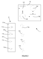
- the positions of the various vibration sensors 11a-11d on the different areas to be monitored 21a-21c of the floor 21 of the railway vehicle 2 are referenced in a correspondence table 123 stored in the processing unit 12, as shown in FIG. figure 3 .
- the different thresholds Vs are also associated with the different zones to be monitored 21a-21c of the floor 21 in said correspondence table 123 (see table below).
- Table 1 Match Table ⁇ / b> Vibration sensor Zone to watch Threshold value 11a 21a Vs1 11b 21b Vs1 11c 21c Vs2 11d 21c Vs2
- the railway vehicle 2 has three areas to monitor 21a-21c, a threshold value Vs having been previously determined for each of them.
- a vibration threshold Vs is defined empirically for each family of zones to be monitored (plates structural steel, cast iron structural plates).
- the area to be monitored 21c has a threshold value Vs2 different from that of the areas to be monitored 21a-21b.
- the structural holding plate, corresponding to the area to be monitored 21c is formed in a material different from that of the structural holding plates corresponding to the areas to be monitored 21a-21b.
- the threshold value Vs1 for the vibration signal 110 of said zone to be monitored 21b is equal to 300 m / s 2 .
- the discrimination module 121 For each vibration signal 110 received by the discrimination module 121, the latter determines the vibration sensor 11a-11d from which the vibration signal 110 originates. By interrogating the correspondence table 123 with which the discrimination module 121 is connected, the discrimination module 121 determines the area to be monitored 21a-21c on which is placed the vibration sensor 11a-11d whose vibration signal 110 is analyzed. Thus, in the event of detection of a ballast impact 3, the discrimination module 121 immediately supplies the area to be monitored 21a-21c struck by the ballast 3.
- the impact index Ci is greater than the threshold value Vs1 of the zone to be monitored 21b.
- An impact is detected by the discrimination module 121 which returns to the processing unit 12 a detection message Mi in which it is indicated that an impact has occurred by specifying the area to be monitored that has received the impact and the instant The detection message Mi indicates that an impact has occurred at time t1 on the zone to be monitored 21b.
- the impact index Ci is less than the threshold value Vs1
- no impact is detected by the discrimination module 121 and no detection message Mi is sent.
- the discrimination module 121 parameterized by the threshold values Vs adapted to each of the zones to be monitored 21a-21d, makes it possible to accurately detect a ballast impact on the floor 21 of the railway vehicle 2.
- the values of the adaptive thresholds Vs make it possible to overcome the background noise constituted by the vibrations of the rolling vehicle 2 during its circulation on the rails, such a monitoring and detection system 1 advantageously making it possible to limit the number of false alarms.
- the discrimination module 121 is arranged to distinguish two successive impacts.
- the discrimination module 121 is set to account for an impact when the impact index Ci is greater than the threshold value Vs for a first time window. No other impact can be counted as long as the impact index Ci is not less than the threshold value Vs for a second time window, subsequent to the first.
- This locking mechanism makes it possible to avoid that the same impact is counted several times by the monitoring and detection system 1.
- the impact index Ci corresponding to the peak-to-peak measurement Vcc, is greater than the threshold value Vs for the time windows T'1, T'2 and T'3.
- a locking signal is activated, preventing the recording of a new impact for the time windows T'2 and T'3.
- the locking signal is deactivated for the time window T'4 in which the peak-to-peak measurement Vcc is lower than the threshold value Vs. This advantageously makes it possible to detect a new impact in the time window T'12.
- the detection and impact monitoring system 1 can be associated with a geolocation system and a cartography. During the journey of the railway vehicle, the detection system transmits the number of impacts detected and the location of the impact on the vehicle. This information is transmitted to the geolocation system which reproduces on a map of the area traveled the number of impacts received. Thus, it is possible to detect on which part of the path the number of impacts is the most important.
- the sectors of the path likely to promote the flight of ballast are shown on the map.
- the sectors of the path favoring the flight of ballast are shown in red.
- the colored cartography is then transmitted to the maintenance agents of the tracks which can then arrange the lanes of circulation to diminish the phenomenon of flight of ballast.
- the detection and monitoring system 1 comprises a plurality of video recording cameras 17a-17d which are mounted on the railway vehicle 2 so as to display one or more areas to be monitored 21a -21c of railway vehicle 2.
- Each video recording camera 17a-17d is here mounted on the outer surface of the floor 21 of the railway vehicle 2 so that at least one area to be monitored 21a-21c of the railway vehicle 2 is included in the viewing angle one of the 17a-17d video recording cameras.
- the video recording cameras 17a-17d used are so-called "fast” cameras because of the high number of images they can record per second (between 100 and 250 images per second). second).
- Each video recording camera 17a-17d is associated with a pre-triggering system allowing, upon receipt of a detection message Mi to obtain a video recording before and after the impact.
- the pre-trigger system comprises for this purpose a buffer memory, or volatile, which includes the data filmed by the camera during the last seconds of recording.
- the buffer memory of the camera includes the data recorded during the last 5 to 10 seconds.
- the contents of the buffer memory are stored in a storage memory (non-volatile memory), the storage memory including the images of the impact.
- the pre-trigger system is arranged to store in memory the data filmed 5 seconds before and 5 seconds after the actual impact of the ballast 3 on the floor 21.
- the video recording cameras 17a, 17b are mounted in different positions on the floor 21 of the railway vehicle 2 and are connected to the processing unit 12, the video recording cameras 17c, 17d not being visible on these FIGS.
- the cameras 17a-17d are here connected in a wired manner but it goes without saying that they could also be connected by a radio link.
- a location table 124 associates for each area to be monitored 21a-21c of the rolling vehicle 2 at least one video recording camera 17a-17d capable of filming said area 21a-21c, c ' that is, the areas to be monitored 21a-21c that are visible by said video recording camera 17a-17d.
- Table 2 Location table 124 ⁇ / b> Zone to watch Recording camera 21a 17a 21b 17a, 17b 21c 17a, 17b, 17c, 17d
- the video recording camera 17a shown on the figure 1 films the structural holding plates 21a and 21b, while the video recording camera 17b only films the structural holding plate 21b.
- the processing unit 12 of the monitoring system 1 further comprises an administration module 122 arranged to control the different video recording cameras 17a-17d as a function of the detection messages Mi emitted by the discrimination module 121.
- the administration module 122 is connected at the input to the output of the discrimination module 121 and at the output to the video recording cameras 17a-17d, the administration module 122 also being in communication with the location table 124 .
- the discrimination module 121 transmits a detection message Mi in which it is indicated that an impact has occurred on an area to be monitored 21a-21c at a given instant. determined. Said detection message Mi is transmitted to administration module 122 of the processing unit 12 which extracts from the detection message Mi the moment of the impact as well as the area to be monitored 21a-21c having received the impact. The reference of the zone 21a-21c is then introduced into the location table 124 which returns in response the references of the video recording cameras 17a-17d which are oriented towards said zone referenced 21a-21c.
- the discrimination module 121 of the processing unit 12 emits a detection message Mi, specifying that the structural plate of holding 21b received an impact.
- the video administration module 122 receives the detection message Mi and consults the location table 124 to determine the video recording cameras to be activated.
- the video recording cameras 17a and 17b are activated (see Table 2).
- the administration module 122 of the processing unit also comprises a video recordings database, not shown, in which the various video recordings recorded by the video recording cameras 17a-17d are stored.
- Vibration sensors in the form of accelerometers have been described here, but it goes without saying that strain gages could also be suitable.
- vibration sensors mounted on the inner surface of the floor but it goes without saying that they could also be mounted on the outer surface. In this case, it is necessary to protect the sensors against external conditions (rain, frost, etc.) but also against shocks related to the ballast.
Abstract
Description
L'invention concerne le domaine de la surveillance des impacts sur un véhicule roulant et, en particulier, les impacts de ballast sur un véhicule ferroviaire circulant à grande vitesse.The invention relates to the field of monitoring the impacts on a rolling vehicle and, in particular, the impact of ballast on a rail vehicle traveling at high speed.
Un véhicule roulant, du type véhicule ferroviaire, est par nature exposé à l'environnement extérieur lors de son déplacement sur des voies de circulation, telles que des rails de chemin de fer reposant sur du ballast.A rolling vehicle, of the railway vehicle type, is by nature exposed to the external environment when traveling on traffic lanes, such as railway rails resting on ballast.
On appelle ballast le lit de pierres ou de graviers sur lequel reposent des rails. Son rôle est de transmettre les efforts engendrés par le passage des véhicules ferroviaires au sol, sans que celui-ci ne se déforme par tassement. Le rôle du ballast est aussi d'enchâsser les rails afin d'assurer une résistance aux déformations longitudinales.Ballast is the bed of stones or gravels on which rails rest. Its role is to transmit the forces generated by the passage of railway vehicles on the ground, without it being deformed by compression. The role of the ballast is also to encase the rails to ensure resistance to longitudinal deformations.
Lors de la circulation d'un véhicule ferroviaire, une force d'aspiration, dépendant de la vitesse du véhicule ferroviaire, se crée entre le véhicule et la voie sur laquelle il circule. En raison de cette force d'aspiration, le ballast décolle du sol, sur lequel il repose, et est propulsé à haute vitesse sur le véhicule ou à proximité des voies. Le ballast entre en collision avec le plancher et les essieux du véhicule ferroviaire. De tels impacts sont néfastes et diminuent la durée de vie des équipements ferroviaires. En outre, de telles projections peuvent également blesser des agents techniques d'entretien situés à proximité des voies de circulation. Ce phénomène est classiquement désigné « envol de ballast ».During the circulation of a rail vehicle, a suction force, depending on the speed of the rail vehicle, is created between the vehicle and the path on which it travels. Because of this suction force, the ballast takes off from the ground on which it rests and is propelled at high speed on the vehicle or near the tracks. The ballast collides with the floor and axles of the rail vehicle. Such impacts are harmful and reduce the life of railway equipment. In addition, such projections may also injure maintenance service agents located near the taxiways. This phenomenon is classically referred to as "ballast flight".
Ce phénomène, bien que déjà connu, revêt une importance de plus en plus grande pour les professionnels du transport ferroviaire en raison de la vitesse de plus en plus élevée des véhicules ferroviaires sur les rails. Afin de mieux comprendre ce phénomène, il a été proposé de mesurer et de modéliser l'envol du ballast.This phenomenon, although already known, is of increasing importance for rail transport professionals due to the increasing speed of railway vehicles on track. To better understand this phenomenon, it has been proposed to measure and model the flight of ballast.
Des méthodes de mesure des projections du ballast lors de la circulation d'un véhicule ferroviaire ont déjà été mises en oeuvre mais n'ont pas permis d'obtenir des résultats satisfaisants.Methods for measuring ballast projections during the running of a railway vehicle have already been implemented but have not yielded satisfactory results.
Ainsi, il est connu par exemple de suspendre des microphones à l'intérieur d'un véhicule ferroviaire à proximité du plancher dudit véhicule de manière à pouvoir écouter les bruits des différents impacts sur la surface extérieure du plancher. Malheureusement, il est difficile de distinguer le bruit des impacts du ballast du bruit de fond, en particulier des vibrations du véhicule ferroviaire lors de sa circulation sur les voies. Les résultats d'une telle méthode sont imprécis et ne permettent pas de tirer de conclusions satisfaisantes.Thus, it is known, for example, to suspend microphones inside a railway vehicle near the floor of said vehicle so as to be able to listen to the noises of the different impacts on the outer surface of the floor. Unfortunately, it is difficult to distinguish between noise and ballast impacts. background noise, in particular vibrations of the railway vehicle during its traffic on the tracks. The results of such a method are imprecise and do not allow to draw satisfactory conclusions.
Un autre inconvénient de ce type de méthode réside dans le fait que lorsqu'un impact est détecté par le microphone, il n'est pas localisable géographiquement. Autrement dit, on ne sait pas à quel endroit du plancher du véhicule ferroviaire le ballast a heurté le plancher. En effet, le bruit de l'impact est reçu quasi simultanément par l'ensemble des microphones, empêchant de déterminer de manière précise la partie du plancher du véhicule qui a été endommagée.Another disadvantage of this type of method lies in the fact that when an impact is detected by the microphone, it is not locatable geographically. In other words, it is not known where the floor of the rail vehicle ballast hit the floor. Indeed, the sound of the impact is received almost simultaneously by the set of microphones, preventing precise determination of the part of the floor of the vehicle that has been damaged.
Afin de remédier à cet inconvénient, il a été proposé d'installer des caméras d'enregistrement vidéo filmant la surface extérieure du plancher du véhicule afin de filmer les impacts. En raison de la vitesse élevée du ballast lorsqu'il est projeté sur le plancher du véhicule, il est approprié d'utiliser des caméras dites « rapides » en raison du nombre élevé d'images qu'elles peuvent enregistrer à la seconde. Ainsi, en comparaison avec une caméra classique, une caméra rapide enregistre un nombre bien plus important de données sur une période de temps similaire et permet ainsi de capturer la trajectoire du ballast lors de son envol.In order to remedy this drawback, it has been proposed to install video recording cameras filming the external surface of the floor of the vehicle in order to film the impacts. Because of the high speed of the ballast when it is projected on the floor of the vehicle, it is appropriate to use so-called "fast" cameras because of the high number of images they can record per second. Thus, in comparison with a conventional camera, a fast camera records a much larger amount of data over a similar period of time and thus captures the trajectory of the ballast during flight.
Pour des tests en conditions réelles sur un trajet du véhicule ferroviaire, la capacité de stockage mémoire de la caméra rapide est limitée et il n'est pas possible de filmer en continu les impacts de ballast pendant toute la durée du test.For real-world tests on a railway vehicle journey, the memory capacity of the fast camera is limited and it is not possible to continuously record ballast impacts for the duration of the test.
Pour obvier à cet inconvénient, une solution consiste à prendre des vues en continu, mais à ne recueillir les enregistrements vidéo que lors d'un impact, c'est-à-dire, lors de la détection d'un bruit d'impact par le microphone. Pour permettre de visualiser l'impact, la caméra est associée à un système de pré-déclenchement permettant, à la réception d'un message de commande d'obtenir un enregistrement vidéo antérieur à l'impact.To obviate this disadvantage, one solution is to take continuous views, but to collect the video recordings only during an impact, that is to say, during the detection of an impact noise by the microphone. To make it possible to visualize the impact, the camera is associated with a pre-trigger system making it possible, upon receipt of a control message, to obtain a video recording prior to the impact.
Le système de pré-déclenchement comprend à cet effet une mémoire tampon, ou volatile, qui comporte les données filmées par la caméra lors des dernières secondes d'enregistrement. D'une manière classique, la mémoire tampon de la caméra comporte les données enregistrées lors des 5 à 10 dernières secondes. Lorsqu'un impact est détecté, le contenu de la mémoire tampon est stocké dans une mémoire de stockage (mémoire non volatile désignée également mémoire morte), la mémoire de stockage comprenant les images de l'impact.The pre-trigger system comprises for this purpose a buffer memory, or volatile, which includes the data filmed by the camera during the last seconds of recording. In a conventional manner, the buffer memory of the camera includes the data recorded during the last 5 to 10 seconds. When an impact is detected, the contents of the buffer are stored in a storage memory (non-volatile memory also designated read-only memory), the storage memory comprising the images of the impact.
Cette méthode de détection et de visualisation des impacts nécessite un opérateur afin qu'il puisse déclencher l'enregistrement vidéo à chaque détection d'impact. En raison du bruit de fond et de la subjectivité de l'opérateur, la détection des impacts est très aléatoire, de nombreux impacts n'étant pas détectés alors que des fausses alertes sont émises.This method of detection and visualization of the impacts requires an operator so that he can trigger the video recording at each impact detection. Because of the background noise and the operator's subjectivity, the detection of impacts is very random, with many impacts not being detected while false alerts are issued.
Du fait de cet inconvénient, il est nécessaire de visualiser l'ensemble des enregistrements vidéo afin de supprimer les enregistrements non pertinents consécutifs aux fausses alertes de détection. Au surplus, il est nécessaire de renouveler cette étape pour l'ensemble des caméras d'enregistrement. Une telle méthode est donc difficile à mettre en oeuvre et ne permet pas d'obtenir des résultats exploitables de manière fiable.Due to this disadvantage, it is necessary to visualize all the video recordings in order to delete irrelevant records resulting from false detection alerts. In addition, it is necessary to repeat this step for all recording cameras. Such a method is therefore difficult to implement and does not make it possible to obtain reliably exploitable results.
Afin de résoudre au moins certains de ces problèmes, la demanderesse propose un procédé de détection d'impacts sur des zones à surveiller d'un véhicule roulant, créés par des objets projetés en raison de sa vitesse, dans lequel on place des capteurs de vibrations en contact direct avec les zones à surveiller dudit véhicule roulant et on analyse les signaux des capteurs de vibrations pour détecter des impacts.In order to solve at least some of these problems, the Applicant proposes a method of detecting impacts on areas to be monitored of a rolling vehicle, created by objects projected due to its speed, in which vibration sensors are placed. in direct contact with the areas to be monitored of said rolling vehicle and the signals of the vibration sensors are analyzed for impacts.
Un tel système de détection permet avantageusement de détecter de manière précise les impacts en mesurant directement la vibration résultant de l'impact sur une zone à surveiller du véhicule roulant. De plus, un impact détecté par un capteur de vibration est localisable sur le véhicule roulant ce qui permet de modéliser le phénomène d'envol de ballast.Such a detection system advantageously makes it possible to accurately detect the impacts by directly measuring the vibration resulting from the impact on an area to be monitored by the rolling vehicle. In addition, an impact detected by a vibration sensor is localisable on the rolling vehicle which allows to model the phenomenon of flight ballast.
L'invention est née suite à la découverte des dommages causés par les impacts de ballast sur un véhicule ferroviaire mais il va de soi que l'invention s'applique à tout véhicule roulant (automobile, avion au décollage/atterrissage, etc.) susceptible de projeter des objets (ballast, gravillons, etc.) en raison de sa vitesse.The invention arose following the discovery of the damage caused by ballast impacts on a railway vehicle, but it goes without saying that the invention applies to any rolling vehicle (automobile, take-off / landing aircraft, etc.) capable of to project objects (ballast, chippings, etc.) because of its speed.
De préférence, on mesure un coefficient d'impact pour chaque signal de vibrations fourni par un capteur de vibrations, on compare chaque coefficient d'impact à une valeur seuil prédéterminée et on émet un message de détection d'impacts lorsque ledit coefficient d'impact excède ladite valeur seuil prédéterminée.Preferably, an impact coefficient is measured for each vibration signal supplied by a vibration sensor, each impact coefficient is compared to a predetermined threshold value and a detection message is transmitted. impact when said impact coefficient exceeds said predetermined threshold value.
La mesure d'un coefficient d'impact sur un signal de vibrations permet de s'affranchir des vibrations du véhicule roulant détectées par les capteurs de vibrations lors du déplacement du véhicule. En effet, on aurait pu également utiliser un réseau de neurones pour déterminer si un signal de vibrations, mesuré par un capteur, représentait un signal d'impact mais un tel réseau de neurones est sensible aux bruits et aux vibrations du véhicule et ne fournit pas de résultats satisfaisants.The measurement of an impact coefficient on a vibration signal makes it possible to overcome the vibrations of the rolling vehicle detected by the vibration sensors during the movement of the vehicle. Indeed, one could also use a neural network to determine if a vibration signal, measured by a sensor, represented an impact signal but such a neural network is sensitive to noise and vibration of the vehicle and does not provide satisfactory results.
De préférence encore, on mesure un coefficient d'impact dudit signal de vibrations sur une fenêtre temporelle de durée prédéterminée.More preferably, an impact coefficient of said vibration signal is measured over a time window of predetermined duration.
La mesure d'impact sur une fenêtre temporelle permet, d'une part, de limiter le nombre de données du signal de vibration à prendre en compte pour calculer le coefficient d'impact et ainsi de permettre la détection en temps réel de l'impact. D'autre part, cela permet de détecter très finement les impacts sur une fenêtre temporelle d'une taille donnée et ainsi de déterminer précisément l'instant de l'impact.The impact measurement on a time window makes it possible, on the one hand, to limit the number of data of the vibration signal to be taken into account in order to calculate the impact coefficient and thus to allow real-time detection of the impact. . On the other hand, this makes it possible to detect very finely the impacts on a window of time of a given size and thus to determine precisely the moment of the impact.
De préférence, la taille de la fenêtre est déterminée en fonction de la durée de la vibration de la zone à surveiller après l'impact.Preferably, the size of the window is determined according to the duration of the vibration of the area to be monitored after the impact.
De préférence encore, après détection d'un impact, on verrouille la détection d'impact tant que le coefficient d'impact dudit signal de vibrations n'est pas inférieur à ladite valeur seuil.More preferably, after detection of an impact, the impact detection is locked as long as the impact coefficient of said vibration signal is not lower than said threshold value.
De préférence toujours, le coefficient d'impact correspond à la mesure crête à crête du signal de vibrations fourni par le capteur de vibrations.Still preferably, the impact coefficient corresponds to the peak-to-peak measurement of the vibration signal provided by the vibration sensor.
Une solution classique aurait consisté à comparer la valeur efficace du signal à une valeur seuil. Cependant, une telle mesure est sensible aux bruits. Etant donné qu'un impact entraîne des vibrations importantes sur une très courte période de temps (proche de l'impulsion), une mesure crête à crête permet de caractériser un impact dans un signal de vibrations de manière rapide et fiable.A conventional solution would have been to compare the rms value of the signal with a threshold value. However, such a measure is sensitive to noise. Since an impact causes significant vibration over a very short period of time (close to the pulse), a peak-to-peak measurement makes it possible to characterize an impact in a vibration signal quickly and reliably.
En effet, un signal d'impact correspond à un bruit impulsionnel dont le niveau moyen est faible et dont le niveau crête à crête est important. En outre, une telle mesure est simple à calculer et peut être réalisée rapidement. Grâce à cette mesure, il est possible de détecter un impact en temps réel.Indeed, an impact signal corresponds to a pulse noise whose average level is low and whose peak-to-peak level is important. In addition, such a measurement is simple to calculate and can be done quickly. Thanks to this measurement, it is possible to detect an impact in real time.
Selon une mise en oeuvre particulière de l'invention, la valeur seuil est fonction de la zone à surveiller du véhicule roulant.According to one particular embodiment of the invention, the threshold value is a function of the area to be monitored of the rolling vehicle.
L'utilisation d'une valeur seuil adaptative dans la mise en oeuvre du procédé de détection d'impacts selon l'invention permet d'adapter la détection selon par exemple la nature de la zone à surveiller (matière, densité, surface) ainsi que de sa réponse en vibration. Ainsi, des zones à surveiller en fonte et en aluminium ne possèdent pas la même valeur seuil, un impact étant détecté dans des conditions qui sont propres à la zone dans laquelle sont disposés les capteurs de vibrations.The use of an adaptive threshold value in the implementation of the impact detection method according to the invention makes it possible to adapt the detection according to, for example, the nature of the zone to be monitored (matter, density, surface) as well as of his response in vibration. Thus, the areas to be monitored cast iron and aluminum do not have the same threshold value, an impact being detected under conditions that are specific to the area in which the vibration sensors are located.
De préférence, le message de détection d'impact comporte la référence de la zone à surveiller qui a reçu l'impact.Preferably, the impact detection message comprises the reference of the area to be monitored that has received the impact.
Cela permet avantageusement de localiser pour chaque impact détecté, la zone à surveiller du véhicule roulant ayant détecté l'impact. On peut ainsi obtenir une carte des localisations des impacts sur le véhicule roulant et modéliser de manière pertinente l'envol de ballast.This advantageously makes it possible to locate for each detected impact, the area to be monitored of the rolling vehicle having detected the impact. It is thus possible to obtain a map of the locations of impacts on the rolling vehicle and to model ballast flight appropriately.
Selon une mise en oeuvre particulière de l'invention, chaque zone à surveiller est associée à au moins une caméra d'enregistrement vidéo apte à filmer ladite zone. On extrait du message de détection d'impacts la référence de la zone à surveiller qui a reçu l'impact et on active uniquement la caméra d'enregistrement vidéo associée à la référence de ladite zone à surveiller.According to one particular embodiment of the invention, each zone to be monitored is associated with at least one video recording camera capable of filming said zone. The reference of the zone to be monitored which has received the impact is extracted from the impact detection message and only the video recording camera associated with the reference of said zone to be monitored is activated.
Cela permet avantageusement de n'activer que les caméras d'enregistrement vidéo qui sont susceptibles de visualiser la projection de l'objet sur le véhicule, évitant ainsi de recourir à une étude systématique de l'ensemble des enregistrements. Le traitement des données enregistrées est alors facilité.This advantageously makes it possible to activate only the video recording cameras which are able to display the projection of the object on the vehicle, thus avoiding resorting to a systematic study of all the recordings. The processing of the recorded data is then facilitated.
L'invention concerne également un système de détection d'impacts sur des zones à surveiller d'un véhicule roulant, créés par des objets projetés en raison de sa vitesse. Le système comporte des capteurs de vibrations en contact direct avec les zones à surveiller dudit véhicule roulant et une unité de traitement de données, reliée à la pluralité de capteurs de vibrations, agencée pour recevoir les signaux de vibrations fournis par la pluralité de capteurs de vibrations et détecter des signaux d'impact parmi lesdits signaux de vibrations pour chacune des zones à surveiller du véhicule roulant.The invention also relates to a system for detecting impacts on areas to be monitored of a rolling vehicle, created by objects projected because of its speed. The system has vibration sensors in direct contact with the areas to be monitored from said rolling vehicle and a data processing unit, connected to the plurality of vibration sensors, arranged to receive the vibration signals provided by the plurality of vibration sensors and to detect impact signals among said vibration signals for each of the areas to be monitored by the moving vehicle.
De préférence, l'unité de traitement comprend un module de discrimination agencé pour:
- mesurer un coefficient d'impact pour chaque signal de vibrations fourni par un capteur de vibrations ;
- comparer ledit coefficient d'impact à une valeur seuil prédéterminée;
- émettre un message de détection d'impact lorsque ledit coefficient d'impact excède ladite valeur seuil prédéterminée.
- measuring an impact coefficient for each vibration signal provided by a vibration sensor;
- comparing said impact coefficient to a predetermined threshold value;
- transmitting an impact detection message when said impact coefficient exceeds said predetermined threshold value.
De préférence encore, l'unité de traitement comprend une table de correspondances, reliée au module de discrimination, associant pour chaque capteur de vibrations la zone à surveiller dans laquelle il est placé.More preferably, the processing unit comprises a correspondence table, connected to the discrimination module, associating for each vibration sensor the area to be monitored in which it is placed.
La table de correspondances permet ainsi de mettre en relation la référence des capteurs avec la localisation des capteurs.The correspondence table thus makes it possible to relate the reference of the sensors to the location of the sensors.
Selon une forme de réalisation particulière de l'invention, l'unité de traitement comprend un module d'administration vidéo dont l'entrée est reliée au module de discrimination et dont la sortie est reliée à une pluralité de caméra d'enregistrement vidéo, le module d'administration vidéo étant agencé pour commander la pluralité de caméras d'enregistrement vidéo en fonction des messages de détection d'impact émis par le module de discrimination.According to a particular embodiment of the invention, the processing unit comprises a video administration module whose input is connected to the discrimination module and the output of which is connected to a plurality of video recording cameras, the video administration module being arranged to control the plurality of video recording cameras according to the impact detection messages emitted by the discrimination module.
De préférence, le module d'administration vidéo est relié à une table de localisation dans laquelle chaque zone à surveiller du véhicule roulant est associée à au moins une caméra d'enregistrement vidéo apte à filmer ladite zone, le module d'administration vidéo étant agencé pour recevoir un message de détection d'impact du module de discrimination, extraire du message de détection d'impact la référence de la zone à surveiller qui a reçu l'impact, transmettre ladite référence de zone à surveiller à la table de localisation, ladite table de localisation retournant en réponse la référence de la caméra d'enregistrement associée à ladite zone à surveiller et commander uniquement l'activation de la caméra d'enregistrement correspondant à la référence de la caméra fournie.Preferably, the video administration module is connected to a location table in which each area to be monitored of the rolling vehicle is associated with at least one video recording camera capable of filming said area, the video administration module being arranged. to receive an impact detection message from the discrimination module, extract the impact detection message from the reference of the zone to be monitored which has received the impact, transmit said reference of the zone to be monitored to the location table, said location table returning in response the reference of the camera recording associated with said area to be monitored and control only the activation of the recording camera corresponding to the camera reference provided.
L'invention sera mieux comprise à l'aide du dessin annexé sur lequel :
- la
figure 1 représente une vue en coupe d'un véhicule ferroviaire équipé d'un système de surveillance selon l'invention dans lequel les capteurs de vibrations dudit système de surveillance sont fixés sur le plancher dudit véhicule ferroviaire ; - la
figure 2 représente une vue de côté schématique de lafigure 2 ; - la
figure 3 représente un diagramme schématique du système de surveillance desfigures 1 ;et 2 - la
figure 4 représente un signal mesuré par un capteur de vibrations du système de surveillance selon l'invention, le signal étant affiché sur un graphique dont l'abscisse indique le temps en seconde et l'ordonnée la valeur des vibrations mesurée dans la direction verticale (m/s2); et - la
figure 5 représente un autre signal mesuré par un capteur de vibrations du système de surveillance selon l'invention, la valeur seuil étant représentée.
- the
figure 1 represents a sectional view of a railway vehicle equipped with a monitoring system according to the invention in which the vibration sensors of said surveillance system are fixed on the floor of said railway vehicle; - the
figure 2 represents a schematic side view of thefigure 2 ; - the
figure 3 represents a schematic diagram of the monitoring system ofFigures 1 and 2 ; - the
figure 4 represents a signal measured by a vibration sensor of the monitoring system according to the invention, the signal being displayed on a graph whose abscissa indicates the time in seconds and the ordinate the value of the vibrations measured in the vertical direction (m / s 2 ); and - the
figure 5 represents another signal measured by a vibration sensor of the monitoring system according to the invention, the threshold value being represented.
Le système de détection et de surveillance d'impacts sur un véhicule roulant selon l'invention va être maintenant présenté pour un véhicule ferroviaire. Il va de soi que l'invention s'applique à d'autres véhicules roulants, en particulier, les véhicules automobiles.The system for detecting and monitoring impacts on a rolling vehicle according to the invention will now be presented for a railway vehicle. It goes without saying that the invention applies to other vehicles, especially motor vehicles.
Dans cet exemple, le système est agencé pour détecter et surveiller les projections de ballast sur le véhicule ferroviaire et en particulier sur la surface extérieure de son plancher ainsi que sur ses essieux. L'invention s'applique à tous les objets projetés sur le véhicule en raison de sa vitesse (ballast, gravillons, etc.).In this example, the system is designed to detect and monitor the ballast projections on the railway vehicle and in particular on the outer surface of its floor and on its axles. The invention applies to all objects projected on the vehicle because of its speed (ballast, chippings, etc.).
En référence à la
Pour rappel, on appelle ballast 3 le lit de pierres ou de graviers sur lequel repose des rails. Son rôle est de transmettre les efforts engendrés par le passage des véhicules ferroviaires au sol, sans que celui-ci ne se déforme par tassement. Le rôle du ballast 3 est aussi d'enchâsser les rails afin d'assurer une résistance aux déformations longitudinales.As a reminder, we call
Dans cet exemple, on considère un véhicule ferroviaire 2 dont le plancher 21 comporte des essieux sur lesquels sont montés des roues qui reposent sur les rails. Le plancher 21 comporte une surface intérieure, tournée vers l'intérieur du véhicule ferroviaire 2, et une surface extérieure tournée vers le sol et le ballast 3.In this example, consider a
En référence aux
Les capteurs de vibrations 11a-11d sont montés dans le véhicule ferroviaire 2 pour capter les vibrations du plancher 21 du véhicule ferroviaire 2 dans la direction verticale, c'est-à-dire dans la direction orthogonale au plan dans lequel s'étend le plancher 21 du véhicule ferroviaire 2. La direction de mesure des vibrations par les capteurs de vibrations 11a-11d est désignée Z sur la
Dans cet exemple, le plancher 21 du véhicule ferroviaire 2 comporte une pluralité de plaques structurales de maintien 21a-21c, ou tôles de maintien, qui forment le plancher 21. Chaque plaque 21a-21c forme une unité de vibrations du fait qu'un impact de ballast 3 sur une partie de la plaque 21a-21c fait vibrer ladite plaque dans son ensemble. Autrement dit, les vibrations résultant d'un impact de ballast 3 sur une plaque 21a-21c donnée ne sont pas transmises aux plaques voisines 21a-21c de ladite plaque 21a-21c ayant reçue l'impact.In this example, the
Les capteurs de vibrations 11a-11d se présentent ici sous la forme d'accéléromètres. Les capteurs de vibrations 11a-11d sont ici choisis de manière à pouvoir mesurer les vibrations résultant d'un impact sur une plaque 21a-21c du plancher 21 afin d'éviter une saturation du capteur de vibrations 11. La gamme de fréquence des capteurs est ici comprise entre 5Hz et 1kHz.The
Les capteurs de vibrations 11a-11d sont ici répartis sur des zones à surveiller du plancher 21 du véhicule ferroviaire 2, les zones à surveiller correspondant aux plaques structurales de maintien 21a-21c du plancher 21.The
Contrairement à une mesure sonore telle qu'elle était réalisée précédemment avec un microphone, la mesure de vibrations au moyen d'un ou plusieurs capteurs de vibrations 11a-11d placés directement sur une plaque structurale de maintien 21a-21c permet d'associer pour chaque impact détecté par l'unité de traitement 12 la plaque 21a-21c qui a été touchée par une projection de ballast 3. Etant donné que chaque plaque 21a-21c forme une unité de vibration, la détection d'un impact par un capteur de vibrations 11 permet de déduire quelle plaque 21a-21c a reçu l'impact.Unlike a sound measurement as it was previously carried out with a microphone, the vibration measurement by means of one or
Le système de détection et de surveillance 1 de l'invention permet non seulement de compter les impacts de ballast mais il permet également de définir en temps réel la localisation des impacts. On qualifie alors ce système de système de détection localisée d'impacts.The detection and
L'unité de traitement 12 du système de surveillance 1 est montée de préférence dans le véhicule ferroviaire 2 et est reliée aux capteurs de vibrations 11a-11d répartis sur les différentes plaques de maintien 21a-21c du plancher 21 du véhicule ferroviaire 2. En référence à la
L'unité de traitement 12 se présente ici comme un ensemble de calculateurs, tels que des ordinateurs et des serveurs, mais il va de soi qu'un seul et unique calculateur pourrait également convenir.The
En référence à la
A cet effet, en référence à la
En référence à la
Les positions des différents capteurs de vibration 11a-11d sur les différentes zones à surveiller 21a-21c du plancher 21 du véhicule ferroviaire 2 sont référencées dans une table de correspondances 123 stockée dans l'unité de traitement 12, comme représentée sur la
En référence à la
En référence à l'exemple de la
Pour chaque signal de vibrations 110 reçu par le module de discrimination 121, celui-ci détermine le capteur de vibrations 11a-11d dont est issu le signal de vibrations 110. Par interrogation de la table de correspondances 123 avec laquelle le module de discrimination 121 est relié, le module de discrimination 121 détermine la zone à surveiller 21a-21c sur laquelle est placé le capteur de vibrations 11a-11d dont le signal de vibrations 110 est analysé. Ainsi, en cas de détection d'un impact de ballast 3, le module de discrimination 121 fournit immédiatement la zone à surveiller 21a-21c heurtée par le ballast 3.For each
Lors de l'étape de comparaison, en référence à la
A l'inverse, toujours en référence à la
Le module de discrimination 121, paramétré par les valeurs seuil Vs adaptées à chacune des zones à surveiller 21a-21d, permet de détecter, de manière précise, un impact de ballast sur le plancher 21 du véhicule ferroviaire 2.The
Les valeurs des seuils adaptatifs Vs permettent de s'affranchir du bruit de fond constitué par les vibrations du véhicule roulant 2 lors de sa circulation sur les rails, un tel système de surveillance et de détection 1 permettant avantageusement de limiter le nombre de fausses alertes.The values of the adaptive thresholds Vs make it possible to overcome the background noise constituted by the vibrations of the rolling
Dans une mise en oeuvre particulière de l'invention, le module de discrimination 121 est agencé pour distinguer deux impacts successifs. A cet effet, le module de discrimination 121 est paramétré pour comptabiliser un impact lorsque l'indice d'impact Ci est supérieur à la valeur seuil Vs pour une première fenêtre temporelle. Aucun autre impact ne peut être comptabilisé tant que l'indice d'impact Ci n'est pas inférieur à la valeur seuil Vs pour une deuxième fenêtre temporelle, postérieure à la première. Ce mécanisme de verrouillage permet d'éviter qu'un même impact soit comptabilisé plusieurs fois par le système de surveillance et de détection 1.In a particular embodiment of the invention, the
En référence à la
Le signal de verrouillage est désactivé pour la fenêtre temporelle T'4 dans laquelle la mesure crête à crête Vcc est inférieure à la valeur seuil Vs. Cela permet avantageusement de détecter un nouvel impact dans la fenêtre temporelle T'12.The locking signal is deactivated for the time window T'4 in which the peak-to-peak measurement Vcc is lower than the threshold value Vs. This advantageously makes it possible to detect a new impact in the time window T'12.
On peut associer le système de détection et de surveillance d'impacts 1 à un système de géolocalisation et à une cartographie. Au cours du trajet du véhicule ferroviaire, le système de détection transmet le nombre d'impacts détectés et le lieu de l'impact sur le véhicule. Ces informations sont transmises au système de géolocalisation qui reproduit sur une cartographie de la zone parcourue le nombre d'impacts reçus. Ainsi, on peut détecter sur quelle partie du trajet le nombre d'impacts est le plus important.The detection and
De manière avantageuse, on représente sur la cartographie les secteurs du trajet susceptibles de favoriser l'envol de ballast. On représente, par exemple, en rouge les secteurs du trajet favorisant l'envol de ballast. La cartographie colorée est ensuite transmise aux agents d'entretien des voies qui peuvent alors aménager les voies de circulation pour diminuer le phénomène d'envol de ballast.Advantageously, the sectors of the path likely to promote the flight of ballast are shown on the map. For example, the sectors of the path favoring the flight of ballast are shown in red. The colored cartography is then transmitted to the maintenance agents of the tracks which can then arrange the lanes of circulation to diminish the phenomenon of flight of ballast.
Dans un mode de réalisation préféré de l'invention, le système de détection et de surveillance 1 comporte une pluralité de caméras d'enregistrement vidéo 17a-17d qui sont montées sur le véhicule ferroviaire 2 de manière à visualiser une ou plusieurs zones à surveiller 21a-21c du véhicule ferroviaire 2.In a preferred embodiment of the invention, the detection and
Chaque caméra d'enregistrement vidéo 17a-17d est ici montée sur la surface extérieure du plancher 21 du véhicule ferroviaire 2 de manière à ce qu'au moins une zone à surveiller 21a-21c du véhicule ferroviaire 2 soit comprise dans l'angle de vision d'une des caméras d'enregistrement vidéo 17a-17d.Each
Comme présenté dans le préambule de la présente demande, les caméras d'enregistrement vidéo 17a-17d utilisées sont des caméras dites « rapides » en raison du nombre élevé d'images qu'elles peuvent enregistrer à la seconde (entre 100 et 250 images par seconde).As presented in the preamble of the present application, the
Chaque caméra d'enregistrement vidéo 17a-17d est associée à un système de pré-déclenchement permettant, à la réception d'un message de détection Mi d'obtenir un enregistrement vidéo antérieur et postérieur à l'impact.Each
Le système de pré-déclenchement comprend à cet effet une mémoire tampon, ou volatile, qui comporte les données filmées par la caméra lors des dernières secondes d'enregistrement. D'une manière classique, la mémoire tampon de la caméra comporte les données enregistrées lors des 5 à 10 dernières secondes. Lors qu'un impact est détecté, le contenu de la mémoire tampon est stocké dans une mémoire de stockage (mémoire non volatile), la mémoire de stockage comprenant les images de l'impact.The pre-trigger system comprises for this purpose a buffer memory, or volatile, which includes the data filmed by the camera during the last seconds of recording. In a conventional manner, the buffer memory of the camera includes the data recorded during the last 5 to 10 seconds. When an impact is detected, the contents of the buffer memory are stored in a storage memory (non-volatile memory), the storage memory including the images of the impact.
En pratique, le système de pré-déclenchement est agencé pour stocker en mémoire les données filmées 5 secondes avant et 5 secondes après le choc effectif du ballast 3 sur le plancher 21.In practice, the pre-trigger system is arranged to store in memory the data filmed 5 seconds before and 5 seconds after the actual impact of the
En référence aux
Une table de localisation 124, représentée sur le tableau 2 ci-dessous, associe pour chaque zone à surveiller 21a-21c du véhicule roulant 2 au moins une caméra d'enregistrement vidéo 17a-17d apte à filmer ladite zone 21a-21c, c'est-à-dire les zones à surveiller 21a-21c qui sont visibles par ladite caméra d'enregistrement vidéo 17a-17d.
Ainsi, la caméra d'enregistrement vidéo 17a représentée sur la
En référence à la
Comme indiqué précédemment, lorsqu'un impact est détecté par un capteur de vibrations 110, le module de discrimination 121 émet un message de détection Mi dans lequel il est indiqué qu'un impact est survenu sur une zone à surveiller 21a-21c à un instant déterminé. Ledit message de détection Mi est transmis au module d'administration 122 de l'unité de traitement 12 qui extrait du message de détection Mi l'instant de l'impact ainsi que la zone à surveiller 21a-21c ayant reçu l'impact. La référence de la zone 21a-21c est ensuite introduite dans la table de localisation 124 qui retourne en réponse les références des caméras d'enregistrement vidéo 17a-17d qui sont orientées en direction de ladite zone référencée 21a-21c.As indicated above, when an impact is detected by a
Ainsi, en reprenant l'exemple précédent, lorsqu'un impact de ballast 3 est détecté par le capteur de vibrations 11b, le module de discrimination 121 de l'unité de traitement 12 émet un message de détection Mi en précisant que la plaque structurale de maintien 21b a reçu un impact. Le module d'administration vidéo 122 reçoit le message de détection Mi et consulte la table de localisation 124 pour déterminer les caméras d'enregistrement vidéo à activer. Ici, comme la plaque structurale de maintien 21b a reçu un impact, les caméras d'enregistrement vidéo 17a et 17b sont activées (voir tableau 2).Thus, taking the previous example, when a
Ainsi, seules les caméras d'enregistrement vidéo 17a, 17b susceptibles de filmer l'envol du ballast 3 sont activées. Le visionnage des enregistrements vidéo en est alors facilité, le nombre d'enregistrements correspondants à des fausses alertes (erreurs de détection) étant très limité.Thus, only the
Dans cet exemple, le module d'administration 122 de l'unité de traitement comporte également une base de données d'enregistrements vidéo, non représentée, dans laquelle les différents enregistrements vidéo, enregistrés par les caméras d'enregistrement vidéo 17a-17d, sont stockés.In this example, the
Il a été ici décrit des capteurs de vibrations se présentant sous la forme d'accéléromètres mais il va de soi que des jauges de contrainte pourraient également convenir.Vibration sensors in the form of accelerometers have been described here, but it goes without saying that strain gages could also be suitable.
En outre, il a été ici décrit des capteurs de vibration monté sur la surface intérieure du plancher mais il va de soi que ces derniers pourraient également être montés sur la surface extérieure. Dans ce cas, il est nécessaire de protéger les capteurs à l'encontre des conditions extérieures (pluie, gel, etc.) mais également contre les chocs liés au ballast.In addition, it has been described here vibration sensors mounted on the inner surface of the floor but it goes without saying that they could also be mounted on the outer surface. In this case, it is necessary to protect the sensors against external conditions (rain, frost, etc.) but also against shocks related to the ballast.
Claims (8)
Applications Claiming Priority (1)
| Application Number | Priority Date | Filing Date | Title |
|---|---|---|---|
| FR0806507A FR2938490B1 (en) | 2008-11-20 | 2008-11-20 | METHOD AND SYSTEM FOR DETECTING IMPACTS ON ZONES TO BE MONITORED ON A ROLLING VEHICLE |
Publications (2)
| Publication Number | Publication Date |
|---|---|
| EP2189353A2 true EP2189353A2 (en) | 2010-05-26 |
| EP2189353A3 EP2189353A3 (en) | 2012-01-25 |
Family
ID=40809933
Family Applications (1)
| Application Number | Title | Priority Date | Filing Date |
|---|---|---|---|
| EP09176657A Withdrawn EP2189353A3 (en) | 2008-11-20 | 2009-11-20 | Method and device to detect impacts on specific zones on a vehicle, especially a railway vehicle |
Country Status (12)
| Country | Link |
|---|---|
| US (1) | US20100127133A1 (en) |
| EP (1) | EP2189353A3 (en) |
| JP (1) | JP2010120635A (en) |
| KR (1) | KR20100056992A (en) |
| CN (1) | CN101898565A (en) |
| AR (1) | AR074200A1 (en) |
| AU (1) | AU2009238357A1 (en) |
| BR (1) | BRPI0908204A2 (en) |
| CA (1) | CA2685989A1 (en) |
| FR (1) | FR2938490B1 (en) |
| MA (1) | MA31421B1 (en) |
| RU (1) | RU2009142728A (en) |
Cited By (1)
| Publication number | Priority date | Publication date | Assignee | Title |
|---|---|---|---|---|
| CN113340709A (en) * | 2021-06-09 | 2021-09-03 | 中国工程物理研究院总体工程研究所 | Mobile load simulation test device and test method |
Families Citing this family (18)
| Publication number | Priority date | Publication date | Assignee | Title |
|---|---|---|---|---|
| US8751045B2 (en) * | 2010-07-29 | 2014-06-10 | Taiwan Semiconductor Manufacturing Company, Ltd. | System and method of monitoring an environmental parameter along a predetermined route |
| US8788220B2 (en) | 2011-01-21 | 2014-07-22 | The United States Of America As Represented By The Secretary Of The Navy | Vehicle damage detection system |
| CN103122602B (en) * | 2011-11-17 | 2014-12-03 | 北京市劳动保护科学研究所 | Steel rail knocking device |
| WO2014039747A1 (en) * | 2012-09-07 | 2014-03-13 | Harsco Corporation | Reference measurement system for rail applications |
| EP2910449B1 (en) * | 2014-02-19 | 2020-05-06 | Bombardier Transportation GmbH | Impact protection for a running gear of a rail vehicle |
| CN103940572B (en) * | 2014-05-09 | 2015-03-11 | 中南大学 | Real vehicle collision test system of rail vehicles |
| DE102015203026A1 (en) | 2015-02-19 | 2016-08-25 | Bayerische Motoren Werke Aktiengesellschaft | Motor vehicle with ballast detection device and method for detecting ballast |
| PL3109124T3 (en) * | 2015-06-23 | 2019-10-31 | Alstom Transp Tech | A railway bogie with a winterproof piping and wiring protecting impact guard |
| KR102502235B1 (en) | 2015-07-16 | 2023-02-21 | 삼성전자주식회사 | Logistic monitoring system and the method |
| DE102015215572A1 (en) * | 2015-08-14 | 2017-02-16 | Siemens Aktiengesellschaft | Test device and method for checking a defined profile of a train of vehicles, especially rail vehicles |
| CN106408686A (en) * | 2016-10-20 | 2017-02-15 | 钟立朋 | Travelling data recorder realizing wide-range shooting |
| CN108305276B (en) * | 2017-11-30 | 2022-04-05 | 浙江康迪智能换电科技有限公司 | Stereo contrast device for vehicle |
| WO2020000374A1 (en) * | 2018-06-29 | 2020-01-02 | 深圳市大疆创新科技有限公司 | Acoustic vibration detection device and racing remote control car |
| US11043044B2 (en) * | 2018-12-04 | 2021-06-22 | Blackberry Limited | Systems and methods for vehicle condition inspection for shared vehicles |
| JP7147671B2 (en) * | 2019-04-11 | 2022-10-05 | トヨタ自動車株式会社 | Information processing system and information processing program |
| KR20210019707A (en) * | 2019-08-13 | 2021-02-23 | 현대자동차주식회사 | Crash monitoring system for vehicle and Crash monitoring method of the same |
| DE102019218951A1 (en) * | 2019-12-05 | 2021-06-10 | Robert Bosch Gmbh | Method and control device for detecting damage to a vehicle |
| CN112816053A (en) * | 2020-12-30 | 2021-05-18 | 武汉第二船舶设计研究所(中国船舶重工集团公司第七一九研究所) | Non-contact vibration information detection method and system for ship equipment |
Citations (3)
| Publication number | Priority date | Publication date | Assignee | Title |
|---|---|---|---|---|
| US5924654A (en) * | 1997-10-06 | 1999-07-20 | Zeftek, Inc. | Railroad car sensing system |
| EP1852326A2 (en) * | 2006-05-03 | 2007-11-07 | Deutsche Bahn AG | Reduction of the moving of particles from the track bed due to turbulence caused by passing trains |
| EP1867545A1 (en) * | 2006-06-14 | 2007-12-19 | Siemens Aktiengesellschaft | Rail vehicle with ballast strike detection means |
Family Cites Families (3)
| Publication number | Priority date | Publication date | Assignee | Title |
|---|---|---|---|---|
| US20030041329A1 (en) * | 2001-08-24 | 2003-02-27 | Kevin Bassett | Automobile camera system |
| US7415337B2 (en) * | 2005-07-26 | 2008-08-19 | Delphi Technologies, Inc. | Method and apparatus for detecting a pedestrian impact |
| US20090001226A1 (en) * | 2007-06-27 | 2009-01-01 | Rftrax, Inc. | Acoustic monitoring of railcar running gear and railcars |
-
2008
- 2008-11-20 FR FR0806507A patent/FR2938490B1/en active Active
-
2009
- 2009-11-19 CA CA2685989A patent/CA2685989A1/en not_active Abandoned
- 2009-11-19 US US12/622,301 patent/US20100127133A1/en not_active Abandoned
- 2009-11-19 BR BRPI0908204-2A patent/BRPI0908204A2/en not_active Application Discontinuation
- 2009-11-19 AR ARP090104466A patent/AR074200A1/en unknown
- 2009-11-20 CN CN2009102584514A patent/CN101898565A/en active Pending
- 2009-11-20 EP EP09176657A patent/EP2189353A3/en not_active Withdrawn
- 2009-11-20 KR KR1020090112849A patent/KR20100056992A/en not_active Application Discontinuation
- 2009-11-20 JP JP2009265379A patent/JP2010120635A/en active Pending
- 2009-11-20 MA MA32360A patent/MA31421B1/en unknown
- 2009-11-20 AU AU2009238357A patent/AU2009238357A1/en not_active Abandoned
- 2009-12-09 RU RU2009142728/11A patent/RU2009142728A/en not_active Application Discontinuation
Patent Citations (3)
| Publication number | Priority date | Publication date | Assignee | Title |
|---|---|---|---|---|
| US5924654A (en) * | 1997-10-06 | 1999-07-20 | Zeftek, Inc. | Railroad car sensing system |
| EP1852326A2 (en) * | 2006-05-03 | 2007-11-07 | Deutsche Bahn AG | Reduction of the moving of particles from the track bed due to turbulence caused by passing trains |
| EP1867545A1 (en) * | 2006-06-14 | 2007-12-19 | Siemens Aktiengesellschaft | Rail vehicle with ballast strike detection means |
Cited By (1)
| Publication number | Priority date | Publication date | Assignee | Title |
|---|---|---|---|---|
| CN113340709A (en) * | 2021-06-09 | 2021-09-03 | 中国工程物理研究院总体工程研究所 | Mobile load simulation test device and test method |
Also Published As
| Publication number | Publication date |
|---|---|
| US20100127133A1 (en) | 2010-05-27 |
| FR2938490A1 (en) | 2010-05-21 |
| AR074200A1 (en) | 2010-12-29 |
| JP2010120635A (en) | 2010-06-03 |
| EP2189353A3 (en) | 2012-01-25 |
| AU2009238357A1 (en) | 2010-06-03 |
| KR20100056992A (en) | 2010-05-28 |
| BRPI0908204A2 (en) | 2013-12-10 |
| MA31421B1 (en) | 2010-06-01 |
| CN101898565A (en) | 2010-12-01 |
| CA2685989A1 (en) | 2010-05-20 |
| RU2009142728A (en) | 2011-06-20 |
| FR2938490B1 (en) | 2014-04-25 |
Similar Documents
| Publication | Publication Date | Title |
|---|---|---|
| EP2189353A2 (en) | Method and device to detect impacts on specific zones on a vehicle, especially a railway vehicle | |
| US8384555B2 (en) | Method and system for automated detection of mobile phone usage | |
| EP1954544B1 (en) | Method and device for the detection of faults in the roundness of wheels of railway stock, and system comprising one such device | |
| EP2096611A1 (en) | Device and method for multi-technology detection of a vehicle | |
| FR3042597A1 (en) | DEVICE AND METHOD FOR CAPTURING AND RECORDING FINE PARTICLES AND / OR NOX GAS DENSITY IN AIR | |
| EP3351452B1 (en) | Method and facility for automatic analysis of the evolution of track geometry | |
| EP3716097A1 (en) | Method for acquiring data captured by a capture module embedded in a mobile device following a predetermined trajectory, corresponding computer program and device | |
| FR2890086A1 (en) | Railway track profile detection method, involves analyzing images of path to obtain real profile, comparing reference profile with real profile, and forming difference signal representing transversal zone, excess or default of ballast | |
| EP3028921A1 (en) | System for monitoring the operating conditions of a train | |
| FR2964216A1 (en) | SYSTEM AND METHOD FOR DETECTING A TARGET OBJECT | |
| EP3631511B1 (en) | System for detecting the crossing of a goal line | |
| EP3601009B1 (en) | Device for detecting rail defects and associated detection method | |
| FR2903519A1 (en) | Motor vehicle classification system for tariffication and collection of toll fee, has video camera for discriminating vehicles from images captured upstream of passage channel and transmitting output data of vehicles to computer | |
| FR3030056B1 (en) | METHOD FOR DETECTING MOBILE ELEMENTS IN A BUILDING AND INSTALLATION FOR IMPLEMENTING SAID METHOD | |
| FR3041595A3 (en) | METHOD AND SYSTEM FOR MEASURING THE BEHAVIOR OF A RAILWAY VEHICLE AND DETECTING DEFECT (S) OF GEOMETRY ON A RAILWAY | |
| FR2913392A1 (en) | Ballast state monitoring device for signaling explosive installation, has information transferring units transferring information towards fixed processing station and another train to detect variation of facies of ballast between two images | |
| EP2845780A1 (en) | Driving-assistance method, method for generating a path indicator, driving-assistance device, and related system | |
| FR2975517A1 (en) | Method for automatic recording of parking position of e.g. car in public parking area, involves storing position of portable device at time of transition from detected displacement state of vehicle to detected stop state of vehicle | |
| EP4080177B1 (en) | Method and system for controlling the maximum noise level related to the movement of a vehicle | |
| FR2936895A1 (en) | AUTONOMOUS PASSIVE SYSTEM USING THE IMAGE ENTRY TO DETECT THE EXCEEDING BY A VEHICLE OF THE LIMITED SPEED | |
| CA2491648C (en) | Process and device used to measure weight applied to the ground by at least one axle | |
| WO2023126328A1 (en) | System for locating a sound source, in particular noise pollution from vehicles | |
| FR3074343A1 (en) | METHOD AND SYSTEM FOR DETECTING GEOMETRY DEFECTS IN A RAILWAY | |
| WO2019170863A1 (en) | Method for detecting an anomaly in the perception by a motor vehicle of its environment | |
| WO2018015655A1 (en) | Method and device for monitoring the movement of people in an environment, particularly in a transport network |
Legal Events
| Date | Code | Title | Description |
|---|---|---|---|
| PUAI | Public reference made under article 153(3) epc to a published international application that has entered the european phase |
Free format text: ORIGINAL CODE: 0009012 |
|
| AK | Designated contracting states |
Kind code of ref document: A2 Designated state(s): AT BE BG CH CY CZ DE DK EE ES FI FR GB GR HR HU IE IS IT LI LT LU LV MC MK MT NL NO PL PT RO SE SI SK SM TR |
|
| PUAL | Search report despatched |
Free format text: ORIGINAL CODE: 0009013 |
|
| AK | Designated contracting states |
Kind code of ref document: A3 Designated state(s): AT BE BG CH CY CZ DE DK EE ES FI FR GB GR HR HU IE IS IT LI LT LU LV MC MK MT NL NO PL PT RO SE SI SK SM TR |
|
| RIC1 | Information provided on ipc code assigned before grant |
Ipc: G01H 1/08 20060101ALI20111219BHEP Ipc: B61K 9/00 20060101ALI20111219BHEP Ipc: B61F 19/00 20060101AFI20111219BHEP |
|
| STAA | Information on the status of an ep patent application or granted ep patent |
Free format text: STATUS: THE APPLICATION IS DEEMED TO BE WITHDRAWN |
|
| 18D | Application deemed to be withdrawn |
Effective date: 20120726 |