EP2189351B1 - Ceiling element for the internal lining of vehicles - Google Patents
Ceiling element for the internal lining of vehicles Download PDFInfo
- Publication number
- EP2189351B1 EP2189351B1 EP09175486A EP09175486A EP2189351B1 EP 2189351 B1 EP2189351 B1 EP 2189351B1 EP 09175486 A EP09175486 A EP 09175486A EP 09175486 A EP09175486 A EP 09175486A EP 2189351 B1 EP2189351 B1 EP 2189351B1
- Authority
- EP
- European Patent Office
- Prior art keywords
- ceiling
- surface element
- ceiling element
- element according
- light
- Prior art date
- Legal status (The legal status is an assumption and is not a legal conclusion. Google has not performed a legal analysis and makes no representation as to the accuracy of the status listed.)
- Not-in-force
Links
Images


Classifications
-
- B—PERFORMING OPERATIONS; TRANSPORTING
- B60—VEHICLES IN GENERAL
- B60R—VEHICLES, VEHICLE FITTINGS, OR VEHICLE PARTS, NOT OTHERWISE PROVIDED FOR
- B60R13/00—Elements for body-finishing, identifying, or decorating; Arrangements or adaptations for advertising purposes
- B60R13/02—Internal Trim mouldings ; Internal Ledges; Wall liners for passenger compartments; Roof liners
- B60R13/0212—Roof or head liners
- B60R13/0225—Roof or head liners self supporting head liners
-
- B—PERFORMING OPERATIONS; TRANSPORTING
- B60—VEHICLES IN GENERAL
- B60Q—ARRANGEMENT OF SIGNALLING OR LIGHTING DEVICES, THE MOUNTING OR SUPPORTING THEREOF OR CIRCUITS THEREFOR, FOR VEHICLES IN GENERAL
- B60Q3/00—Arrangement of lighting devices for vehicle interiors; Lighting devices specially adapted for vehicle interiors
- B60Q3/70—Arrangement of lighting devices for vehicle interiors; Lighting devices specially adapted for vehicle interiors characterised by the purpose
- B60Q3/74—Arrangement of lighting devices for vehicle interiors; Lighting devices specially adapted for vehicle interiors characterised by the purpose for overall compartment lighting; for overall compartment lighting in combination with specific lighting, e.g. room lamps with reading lamps
-
- B—PERFORMING OPERATIONS; TRANSPORTING
- B61—RAILWAYS
- B61D—BODY DETAILS OR KINDS OF RAILWAY VEHICLES
- B61D17/00—Construction details of vehicle bodies
- B61D17/04—Construction details of vehicle bodies with bodies of metal; with composite, e.g. metal and wood body structures
- B61D17/18—Internal lining, e.g. insulating
-
- B—PERFORMING OPERATIONS; TRANSPORTING
- B60—VEHICLES IN GENERAL
- B60R—VEHICLES, VEHICLE FITTINGS, OR VEHICLE PARTS, NOT OTHERWISE PROVIDED FOR
- B60R13/00—Elements for body-finishing, identifying, or decorating; Arrangements or adaptations for advertising purposes
- B60R13/02—Internal Trim mouldings ; Internal Ledges; Wall liners for passenger compartments; Roof liners
- B60R2013/0287—Internal Trim mouldings ; Internal Ledges; Wall liners for passenger compartments; Roof liners integrating other functions or accessories
Definitions
- the invention relates to a ceiling part for vehicle interior trim, in particular for the ceiling of public transport vehicles.
- the practice of rail vehicle construction offers a ceiling cladding, which is usually carried out in sheet metal.
- the lighting is designed as a direct central lighting, attached to the ceiling paneling and provided with a luminaire trim. These panels are usually made of plastic.
- the practice has hitherto offered a usually executed in plastic ceiling assembly to which the lighting is mounted during assembly, which usually consists of one or two fluorescent tubes or can be designed as a lamp of another type.
- a separate cladding of the lamp usually consists of one or two fluorescent tubes or can be designed as a lamp of another type.
- the module has a base frame, which can be mounted on suitable supporting elements in the roof area, for fastening parts of the inner ceiling lining as well as assembly parts, such as the lighting, on.
- the base frame which is designed as an adapter frame with adaptable to the respective support elements stop means, a pivotally mounted ceiling support frame is assigned.
- the ceiling support frame carries over the vehicle width extending inner ceiling panel.
- the DE 296 07 932 discloses an interior lining of the ceiling area of vehicles, in particular rail vehicles, which is formed from ceiling panels and lights.
- the ceiling panels are removably received at their running in the vehicle longitudinal longitudinal edges of profiles.
- the lights are arranged in the vehicle center and form part of an air duct.
- a base body is spaced apart in each case in a roof-shaped depression of the air channel and formed as part of ending in air outlet openings air distribution channels.
- Another variant used in practice is a separate solution, in which the ceiling panel is attached and a separate lighting assembly in the lamp and panel are already combined to form an assembly is provided. Although the assembly is already facilitated compared to the variants described above, However, increased expenses during assembly and, if necessary, to adapt the different modules to each other are required.
- the invention is therefore based on the object, a ceiling part to the vehicle interior trim in such a way that facilitates installation in the vehicle and a secure cover of the lights is possible.
- a ceiling part for vehicle interior trim which comprises a structural assembly of profile elements, which are arranged in the form of a cross-over reinforcement.
- the cover part comprises a surface element, which is designed as a hat profile with trapezoidal legs of a translucent plastic, and has a plurality of functional areas.
- the structural assembly is connected to the back of the surface element and this three-dimensionally stabilizing.
- Subareas of the surface element have a satined coating on the back and a light-tight coating on the front.
- an area with continuous recesses on the surface element is formed on the surface element.
- the profile elements of the structural assembly are designed as Kunststoffhutprofile, Aluminiumvierkantformmaschine and Aluminiumvierkanthohlprofile.
- the structural assembly and / or the surface element is formed so that a lighting assembly is receivable.
- the surface element consists of a thermoplastic material. As a continuous recesses a punched perforation in the surface element is provided.
- the functional area of the light exit opening is formed by masking by means of a light-tight coating on the front side of the light-transmitting area element.
- the light color at the exit of the light through the light exit opening from the ceiling part can be selected by means of the satin coating on the back of the surface element.
- the coating of the surface element is formed as a lacquer.
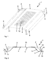
- FIG. 1 shows a ceiling part 1 to the vehicle interior trim in a perspective view, installed in the vehicle and viewed from below from the passenger compartment out.
- the surface element 3 is arched upward to the ceiling of the vehicle and forms a large hat profile. Down into the vehicle interior, the areas are curved, which have the locks 9 and the hinges 8 and are designed as trapezoidal legs.
- the surface element 3 consists of a translucent plastic.
- the structural assembly 2 which consists of profile elements, which are arranged in the form of a cross-over reinforcement and connected to the back 5 of the surface element 3. As a result, the surface element 3 is stabilized three-dimensionally and secured against bending and twisting.
- the surface element 3 has various light-, air- and sound-permeable functional areas.
- the continuous recesses 4, locally formed as a speaker opening 12 are, and permeable to air and sound, the areas with satin coating, which form the light exit opening 11, translucent.
- the front side 6 of the surface element which points into the car interior, is provided with a light-tight coating.
- the middle part of the upwardly curved surface element 3 has the continuous recesses 4.
- Centrally located in the region of the continuous recesses 4 are the continuous recesses as speaker opening 12.
- the recesses 4 and 12 are grid-like arranged perforations.
- the recesses 12, which are formed as speaker openings, have a larger diameter than the recesses 4 of the remaining area. In the remaining area, the continuous recesses 4 serve the Sound absorption to create an air-permeable connection to the passenger compartment.
- FIG. 2 shows the ceiling part 1 in a side view, that is seen in the direction of travel of the vehicle. Visible is the surface element 3, which bulges in the central region to the top and at the lateral areas down to the passenger compartment, drops.
- the sloping regions have the light exit opening 11, a transparent area of the surface element 3. This is formed by a masking, which takes place during the application of the light-tight coating 6 on the front side of the surface element 3 and the area of the light exit opening 11.
- the light-tight coating on the front side 6 covers all other areas of the surface element 3 such that no light can pass through. This creates a light-tight area on the surface element 3, the front 6 with a light-tight coating.
- the rear side 5 of the surface element 3 is provided with a satin-coated coating so that the integratable illumination assembly 7 can not be seen from the passenger compartment through the light exit opening 11 and only the light can shine through.
- the lacquer applied to the back 5 with a satin-finished coating for producing the coating produces a frosted glass effect on the back 5 of the surface element 3.
- This frosted glass effect of the satin-finished coating 5 furthermore prevents the structural assembly 2 from being recognizable from the passenger compartment.
- the back side 5 with the satin-finished coating determines the color of the light when the light emerges through the light exit opening 11 from the ceiling part 1 in accordance with the selected paint color.
- the structural assembly 2 is used to attach the cover part 1 on the vehicle upper side and stabilizes the surface element 3.
- the structural assembly 2 consists of Kunststoffhutprofilen 15, in the aluminum square moldings 17 are integrated.
- the aluminum square moldings 17 are connected to aluminum U-profiles 13, which carry on the left side of the hinge system 8 and on the right side, in the FIG. 2 recognizable, the lock 9.
- the surface element 3 has centrally the continuous recesses 4.
- the integrable lighting assembly 7 is not shown. It is in the area above the light exit opening 11 on both sides of the ceiling element 1, between the ceiling part 1 and vehicle ceiling, preferably on the ceiling part 1 itself, attached.
- FIG. 3 shows the ceiling part 1 from below, viewed from the passenger compartment out. Also included in the surface element 3 is the area of the continuous recesses 4. Within this area, the continuous recesses are still visible as loudspeaker opening 12, through a perforation with enlarged openings is formed. Downwards, the second light exit opening 11 connects. At the bottom in FIG. 3 the locks 9 and the safety ropes 10 are attached.
- the here visible front 6 with light-tight coating saves the masking by the coating, which is preferably carried out by paint, formed light exit openings 11, so that no light can pass through all other areas of the surface element 3.
- FIG. 4 shows the back 5 of the ceiling part 1, which is not visible when installed from the passenger compartment out.
- the hinge systems. 8 visible, noticeable.
- the locks 9 and the safety ropes 10 can be seen as well as in the previous illustrations.
- the surface element 3 has on the entire back 5 satined paint, which is also referred to as frost paint.
- the middle region of the surface element 3 has the region of the continuous recesses 4, in the middle of which is arranged on the right side, the continuous recesses as a speaker opening 12 is located.
- the rear view 5 of the ceiling part 1 is characterized in particular by the structural assembly 2.
- the structural assembly 2 consists of plastic and metal elements, which are formed in the form of a cross-over reinforcement as Kunststoffhutprofile 15 and 14 aluminum square profiles.
- the Kunststoffhutprofile 15 cover in the central region of the aluminum square profiles 14. These are shown in the central region in a concealed representation.
- the aluminum U-profiles 13 are shown, which are bolted to the aluminum square profiles 14.
- the gain in the horizontal direction, relative to the representation in FIG. 4 The vertical reinforcement is carried out by Aluminiumvierkanthohlprofile 17, in which the aluminum square profiles 14 are inserted and secured therein.
- the Kunststoffhutprofile 15 are glued to the surface element 3.
- the compound of the surface element 3 with the aluminum U-profile 13 is carried out by gluing.
- the attached to the aluminum U-profile 13 hinge systems 8 and 9 locks are attached by screwing.
Abstract
Description
Die Erfindung betrifft ein Deckenteil zur Fahrzeuginnenverkleidung, insbesondere für die Decke von Fahrzeugen des öffentlichen Personenverkehrs.The invention relates to a ceiling part for vehicle interior trim, in particular for the ceiling of public transport vehicles.
Dazu bietet die Praxis des Schienenfahrzeugbaus eine Deckenverkleidung, die zumeist in Metallblech ausgeführt ist. Die Beleuchtung wird, als direkte Zentralbeleuchtung ausgeführt, an der Deckenverkleidung befestigt und mit einer Leuchtenverkleidung versehen. Diese Verkleidungen bestehen üblicherweise aus Kunststoff.For this purpose, the practice of rail vehicle construction offers a ceiling cladding, which is usually carried out in sheet metal. The lighting is designed as a direct central lighting, attached to the ceiling paneling and provided with a luminaire trim. These panels are usually made of plastic.
Dieser Lösung haftet der Nachteil an, dass die Deckenverkleidung, die Beleuchtung und die Leuchtenverkleidung bei der Montage des Fahrzeugs mit hohem Aufwand zusammengefügt werden müssen.This solution has the disadvantage that the ceiling panel, the lighting and the lighting panel must be assembled with great effort during assembly of the vehicle.
Als weitere Lösung bietet die Praxis bislang eine üblicherweise in Kunststoff ausgeführte Deckenbaugruppe, an die während der Montage die Beleuchtung angebracht wird, die zumeist aus einer oder zwei Leuchtstoffröhren besteht oder auch als Leuchte anderer Bauart ausgeführt sein kann. Auch hierbei erfolgt eine gesonderte Verkleidung der Leuchte.As a further solution, the practice has hitherto offered a usually executed in plastic ceiling assembly to which the lighting is mounted during assembly, which usually consists of one or two fluorescent tubes or can be designed as a lamp of another type. Here, too, a separate cladding of the lamp.
Auch dieser Lösung haftet der Nachteil an, dass die Deckenverkleidung, die Beleuchtung und die Leuchtenverkleidung bei der Montage des Fahrzeugs mit hohem Aufwand zusammengefügt werden müssen.This solution also has the disadvantage that the ceiling panel, the lighting and the lighting panel must be assembled with great effort during assembly of the vehicle.
Aus der
Auch die
Eine weitere in der Praxis angewandte Variante ist eine getrennte Lösung, bei der die Deckenverkleidung angebracht wird und eine separate Beleuchtungsbaugruppe, bei der Leuchte und Verkleidung bereits zu einer Baugruppe zusammengefasst sind, vorgesehen ist. Hierbei ist zwar die Montage gegenüber den zuvor beschriebenen Varianten bereits erleichtert, jedoch sind erhöhte Aufwendungen bei der Montage und erforderlichenfalls zur Anpassung der unterschiedlichen Baugruppen aneinander erforderlich.Another variant used in practice is a separate solution, in which the ceiling panel is attached and a separate lighting assembly in the lamp and panel are already combined to form an assembly is provided. Although the assembly is already facilitated compared to the variants described above, However, increased expenses during assembly and, if necessary, to adapt the different modules to each other are required.
Weitere Nachteile und Mängel sind:
- die Befestigungsmittel zur Montage während des Fahrzeugaufbaus sind schwerer gegen selbstständiges Lösen durch Vibrationen zu sichern,
- offene, im Fahrgastraum befindliche Leuchten verschmutzen leicht und können Ziel von Vandalismus sein und sind in zerstörtem oder beschädigtem Zustand eine Gefahr hinsichtlich eines elektrischen Schlags bei Berührung,
- die Lichtfarbe kann allein durch Auswahl des Leuchtmittels erfolgen,
- die Zugänglichkeit der Decke, z. B. zur Überprüfung von Leitungsführungen im Deckenbereich, ist eingeschränkt und nur durch Demontage von Beleuchtung und Deckenverkleidung bzw. begrenzt durch Öffnungen in der Deckenverkleidung möglich.
- the fastening means for mounting during vehicle construction are more difficult to secure against self-loosening by vibrations,
- open luminaires located in the passenger compartment are easily soiled and may be subject to vandalism and, when destroyed or damaged, present a risk of shock when touched,
- the light color can be done solely by selecting the light source,
- the accessibility of the ceiling, z. As for the verification of cable routing in the ceiling area, is limited and only by disassembly of lighting and ceiling paneling or limited by openings in the ceiling panel possible.
Der Erfindung liegt deshalb die Aufgabe zugrunde, ein Deckenteil zur Fahrzeuginnenverkleidung derart weiterzubilden, dass die Montage im Fahrzeug erleichtert und eine sichere Abdeckung der Leuchten möglich wird.The invention is therefore based on the object, a ceiling part to the vehicle interior trim in such a way that facilitates installation in the vehicle and a secure cover of the lights is possible.
Die Aufgabe wurde gelöst durch ein Deckenteil zur Fahrzeuginnenverkleidung, das eine Strukturbaugruppe aus Profilelementen umfasst, die in Form einer Überkreuzverstärkung angeordnet sind. Weiterhin umfasst das Deckenteil ein Flächenelement, das als Hutprofil mit trapezförmigen Schenkeln aus einem lichtdurchlässigen Kunststoff ausgebildet ist, und mehrere Funktionsbereiche aufweist. Die Strukturbaugruppe ist mit der Rückseite des Flächenelementes und dieses dreidimensional stabilisierend verbunden. Teilbereiche des Flächenelementes weisen auf der Rückseite eine satinierte Beschichtung und auf der Vorderseite eine lichtdichte Beschichtung auf. Dadurch werden auf dem Flächenelement licht-, luft- und schalldurchlässige Funktionsbereiche ausgebildet. Weiterhin ist am Flächenelement ein Bereich mit durchgängigen Ausnehmungen am Flächenelement ausgebildet.The object was achieved by a ceiling part for vehicle interior trim, which comprises a structural assembly of profile elements, which are arranged in the form of a cross-over reinforcement. Furthermore, the cover part comprises a surface element, which is designed as a hat profile with trapezoidal legs of a translucent plastic, and has a plurality of functional areas. The structural assembly is connected to the back of the surface element and this three-dimensionally stabilizing. Subareas of the surface element have a satined coating on the back and a light-tight coating on the front. As a result, on the surface element light, air and sound-permeable functional areas educated. Furthermore, an area with continuous recesses on the surface element is formed on the surface element.
Die Profilelemente der Strukturbaugruppe sind als Kunststoffhutprofile, Aluminiumvierkantformteile und Aluminiumvierkanthohlprofile ausgebildet. Zudem ist die Strukturbaugruppe und/oder das Flächenelement so ausgebildet, dass eine Beleuchtungsbaugruppe aufnehmbar ist.The profile elements of the structural assembly are designed as Kunststoffhutprofile, Aluminiumvierkantformteile and Aluminiumvierkanthohlprofile. In addition, the structural assembly and / or the surface element is formed so that a lighting assembly is receivable.
Das Flächenelement besteht aus einem thermoplastischen Werkstoff. Als durchgängige Ausnehmungen ist eine gestanzte Lochung im Flächenelement vorgesehen.The surface element consists of a thermoplastic material. As a continuous recesses a punched perforation in the surface element is provided.
Der Funktionsbereich der Lichtaustrittsöffnung ist mittels einer lichtdichten Beschichtung der Vorderseite des lichtdurchlässigen Flächenelements durch Maskierung ausgebildet. Die Lichtfarbe beim Austritt des Lichts durch die Lichtaustrittsöffnung aus dem Deckenteil ist mittels der satinierten Beschichtung der Rückseite des Flächenelementes auswählbar.The functional area of the light exit opening is formed by masking by means of a light-tight coating on the front side of the light-transmitting area element. The light color at the exit of the light through the light exit opening from the ceiling part can be selected by means of the satin coating on the back of the surface element.
Am Deckenteil sind nach einer bevorzugten Ausgestaltung der Erfindung Fangseile vorgesehen, die beim Öffnen der Deckenverkleidung das Herunterklappen des Deckenteils begrenzen. Weiterhin sind vorteilhaft ein Scharniersystem und ein Schloss am Deckenteil vorgesehen. Die Beschichtung des Flächenelementes ist als Lack ausgebildet.On the ceiling part catching cables are provided according to a preferred embodiment of the invention, which limit the folding down of the ceiling part when opening the ceiling panel. Furthermore, a hinge system and a lock are advantageously provided on the ceiling part. The coating of the surface element is formed as a lacquer.
Weitere Einzelheiten, Merkmale und Vorteile der Erfindung ergeben sich aus der nachfolgenden Beschreibung eines Ausführungsbeispiels mit Bezugnahme auf die zugehörigen Zeichnungen. Es zeigen:
- Fig. 1:
- Deckenteil in perspektivischer Sicht von unten,
- Fig. 2:
- Deckenteil in Seitenansicht,
- Fig. 3:
- Deckenteil Vorderseite und
- Fig. 4:
- Deckenteil Rückseite.
- Fig. 1:
- Ceiling part in perspective view from below,
- Fig. 2:
- Ceiling part in side view,
- 3:
- Ceiling front and side
- 4:
- Ceiling part back.
Zur Verstärkung des Deckenteils 1 dient die Strukturbaugruppe 2. Diese besteht aus Profilelementen, die in Form einer Überkreuzverstärkung angeordnet und mit der Rückseite 5 des Flächenelements 3 verbunden sind. Dadurch wird das Flächenelement 3 dreidimensional stabilisiert und gegen Verbiegen und Verwinden gesichert.To reinforce the ceiling part 1 is the
Das Flächenelement 3 weist verschiedene licht-, luft- und schalldurchlässige Funktionsbereiche auf. Die durchgängigen Ausnehmungen 4, lokal als Lautsprecheröffnung 12 ausgebildet, sind und luft- und schalldurchlässig, die Bereiche mit satinierter Beschichtung, die die Lichtaustrittsöffnung 11 bilden, lichtdurchlässig.The
Die Vorderseite 6 des Flächenelements, die in das Wageninnere weist, ist mit lichtdichter Lackierung versehen. Der mittlere Teil des nach oben gewölbten Flächenelements 3 weist die durchgängigen Ausnehmungen 4 auf. Zentral angeordnet im Bereich der durchgängigen Ausnehmungen 4 befinden sich die durchgängigen Ausnehmungen als Lautsprecheröffnung 12. Die Ausnehmungen 4 und 12 sind rasterartig angeordnete Lochungen. Die Ausnehmungen 12, die als Lautsprecheröffnungen ausgebildet sind, weisen einen größeren Durchmesser auf als die Ausnehmungen 4 des übrigens Bereichs. Im übrigen Bereich dienen die durchgängigen Ausnehmungen 4 der Schallabsorption, um eine luftdurchlässige Verbindung zum Fahrgastraum zu schaffen.The
Die Rückseite 5 des Flächenelements 3 ist mit satinierter Beschichtung versehen, so dass durch die Lichtaustrittsöffnung 11 hindurch die integrierbare Beleuchtungsbaugruppe 7 aus dem Fahrgastraum heraus nicht erkennbar ist und nur das Licht hindurchscheinen kann.The
Der auf die Rückseite 5 mit satinierter Beschichtung zum Herstellen der Beschichtung aufgebrachte Lack, erzeugt einen Milchglaseffekt auf der Rückseite 5 des Flächenelements 3. Dieser Milchglaseffekt der satinierten Beschichtung 5 verhindert weiterhin, dass aus dem Fahrgastraum heraus die Strukturbaugruppe 2 erkennbar wird. Die Rückseite 5 mit der satinierten Beschichtung bestimmt entsprechend der ausgewählten Lackfarbe die Lichtfarbe beim Austritts des Lichts durch die Lichtaustrittsöffnung 11 aus dem Deckenteil 1.The lacquer applied to the
Die Strukturbaugruppe 2 dient der Befestigung des Deckenteils 1 an der Fahrzeugoberseite und stabilisiert das Flächenelement 3. Die Strukturbaugruppe 2 besteht aus Kunststoffhutprofilen 15, in die Aluminiumvierkantformteile 17 integriert sind. Die Aluminiumvierkantformteile 17 sind verbunden mit Aluminium-U-Profilen 13, die auf der linken Seite das Scharniersystem 8 tragen und auf der rechten Seite, in der
Die integrierbare Beleuchtungsbaugruppe 7 ist nicht dargestellt. Sie ist im Bereich oberhalb der Lichtaustrittsöffnung 11 auf beiden Seiten des Deckenelements 1, zwischen Deckenteil 1 und Fahrzeugdecke, bevorzugt am Deckenteil 1 selbst, angebracht.The
Die Rückansicht 5 des Deckenteils 1 wird insbesondere durch die Strukturbaugruppe 2 geprägt. Die Strukturbaugruppe 2 besteht aus Kunststoff und Metallelementen, die in Form einer Überkreuzverstärkung als Kunststoffhutprofile 15 und Aluminiumvierkantprofile 14 ausgebildet sind. Die Kunststoffhutprofile 15 überdecken im mittleren Bereich die Aluminiumvierkantprofile 14. Diese sind in dem mittleren Bereich in verdeckter Darstellung gezeigt. Die Befestigung der Aluminiumvierkantprofile 14 an den Kunststoffhutprofilen 15 erfolgt durch Schrauben 16.The
Im oberen sowie im unteren Bereich der
Die Kunststoffhutprofile 15 sind mit dem Flächenelement 3 verklebt. Damit erfolgt zugleich die Fixierung der Aluminiumvierkanthohlprofile 17 innerhalb der Kunststoffhutprofile 15 sowie auf dem Flächenelement 3. Auch die Verbindung des Flächenelements 3 mit dem Aluminium-U-Profil 13 erfolgt durch Verklebung. Die an dem Aluminium-U-Profil 13 befestigten Scharniersysteme 8 sowie Schlösser 9 sind durch Verschraubung angebracht.The
- 11
- Deckenteilcover part
- 22
- Strukturbaugruppestructural assembly
- 33
- Flächenelementsurface element
- 44
- durchgängige Ausnehmungencontinuous recesses
- 55
- Rückseite mit satinierter BeschichtungBack with satined coating
- 66
- Vorderseite mit lichtdichter BeschichtungFront side with light-tight coating
- 77
- integrierbare Beleuchtungsbaugruppeintegrable lighting module
- 88th
- Scharniersystemhinge system
- 99
- Schlosslock
- 1010
- FangseilSafety wire
- 1111
- LichtaustrittsöffnungLight opening
- 1212
- durchgängige Ausnehmungen als Lautsprecheröffnungcontinuous recesses as loudspeaker opening
- 1313
- Aluminium-U-ProfileAluminum U-profiles
- 1414
- AluminiumvierkantprofileAluminum square profiles
- 1515
- KunststoffhutprofileKunststoffhutprofile
- 1616
- Schraubenscrew
- 1717
- AluminiumvierkanthohlprofileAluminum square hollow sections
Claims (11)
- A ceiling element for the internal lining of a vehicle, characterized by- a structure assembly (2) of profile elements, which are arranged in the form of a cross-over reinforcement, and- a surface element (3), which is constructed as a hat-like profile with trapezoidal side pieces made of a translucent plastic and has several functional areas, wherein- the structure assembly (2) is connected with the rear side (5) of the surface element (3) and stabilizing the latter three-dimensionally.
- The ceiling element according to Claim 1, characterized in that on the surface element (3) for the formation of functional areas permeable to light, air and sound, partial areas of the surface element (3) on the rear side (5) have a satined coating and on the front side (6) have an opaque coating and that in addition on the surface element (3) an area is formed with continuous openings (4, 12) on the surface element (3).
- The ceiling element according to Claim 1 or 2, characterized in that the profile elements of the structure assembly (2) are constructed as plastic hat-like profiles (15), aluminium square shaped parts (14) and aluminium square hollow profiles (17).
- The ceiling element according to one of Claims 1 to 3, characterized in that the structure assembly (2) and/or the surface element (3) is constructed so as to be able to receive a lighting assembly (7).
- The ceiling element according to one of Claims 1 to 4, characterized in that the surface element (3) consists of a thermoplastic material.
- The ceiling element according to one of Claims 1 to 5, characterized in that as continuous openings (4, 12) a punched perforation is provided in the surface element (3).
- The ceiling element according to one of Claims 1 to 6, characterized in that the functional area of the light outlet opening (11) is formed by masking by means of an opaque coating of the front side (6) of the translucent surface element (3).
- The ceiling element according to one of Claims 1 to 7, characterized in that the light temperature on emergence of the light through the light outlet opening (11) from the ceiling element (1) is able to be selected by means of the satined coating of the rear side (5) of the surface element (3).
- The ceiling element according to one of Claims 1 to 8, characterized in that retaining cables (10) are provided on the ceiling element (1), which on opening of the ceiling lining delimit the folding down of the ceiling element (1).
- The ceiling element according to one of Claims 1 to 9, characterized in that a hinge system (8) and a lock (9) are provided on the ceiling element (1).
- The ceiling element according to one of Claims 1 to 10, characterized in that the coating of the surface element (3) is formed as a lacquer.
Applications Claiming Priority (1)
| Application Number | Priority Date | Filing Date | Title |
|---|---|---|---|
| DE202008015417U DE202008015417U1 (en) | 2008-11-21 | 2008-11-21 | Ceiling part for vehicle interior trim |
Publications (2)
| Publication Number | Publication Date |
|---|---|
| EP2189351A1 EP2189351A1 (en) | 2010-05-26 |
| EP2189351B1 true EP2189351B1 (en) | 2012-02-15 |
Family
ID=40340454
Family Applications (1)
| Application Number | Title | Priority Date | Filing Date |
|---|---|---|---|
| EP09175486A Not-in-force EP2189351B1 (en) | 2008-11-21 | 2009-11-10 | Ceiling element for the internal lining of vehicles |
Country Status (3)
| Country | Link |
|---|---|
| EP (1) | EP2189351B1 (en) |
| AT (1) | ATE545562T1 (en) |
| DE (1) | DE202008015417U1 (en) |
Families Citing this family (6)
| Publication number | Priority date | Publication date | Assignee | Title |
|---|---|---|---|---|
| AT13166U1 (en) * | 2012-04-02 | 2013-07-15 | Seisenbacher Gmbh | Ceiling element for rail vehicles |
| DE102013212454B3 (en) | 2013-06-27 | 2014-11-20 | Siemens Aktiengesellschaft | Interior ceiling arrangement of a rail vehicle |
| CN108974025B (en) * | 2017-06-05 | 2020-06-09 | 中车唐山机车车辆有限公司 | Integrated section bar and train |
| DE102018117700A1 (en) * | 2018-07-23 | 2020-01-23 | Webasto SE | Roof assembly of a vehicle roof with a lighting device |
| DE102018212966A1 (en) * | 2018-08-02 | 2020-02-06 | Siemens Mobility GmbH | cladding element |
| DE102019134147A1 (en) * | 2019-12-12 | 2021-06-17 | Bayerische Motoren Werke Aktiengesellschaft | Vehicle with improved speaker layout |
Family Cites Families (3)
| Publication number | Priority date | Publication date | Assignee | Title |
|---|---|---|---|---|
| US4171535A (en) * | 1977-10-28 | 1979-10-16 | Westinghouse Electric Corp. | Luminaire for concealed T ceiling systems |
| DE29607932U1 (en) | 1996-05-02 | 1996-06-20 | Deutsche Waggonbau Ag | Interior lining of the ceiling area of vehicles, especially rail vehicles |
| DE102005048289B4 (en) | 2005-10-08 | 2007-07-05 | Maschinenbau Und Service Gmbh Ammendorf | Interior module for ceiling areas of vehicles, in particular rail vehicles for passenger transport |
-
2008
- 2008-11-21 DE DE202008015417U patent/DE202008015417U1/en not_active Expired - Lifetime
-
2009
- 2009-11-10 AT AT09175486T patent/ATE545562T1/en active
- 2009-11-10 EP EP09175486A patent/EP2189351B1/en not_active Not-in-force
Also Published As
| Publication number | Publication date |
|---|---|
| ATE545562T1 (en) | 2012-03-15 |
| DE202008015417U1 (en) | 2009-02-05 |
| EP2189351A1 (en) | 2010-05-26 |
Similar Documents
| Publication | Publication Date | Title |
|---|---|---|
| EP2189351B1 (en) | Ceiling element for the internal lining of vehicles | |
| DE2125637C3 (en) | Support structure for the ceiling panels of a suspended ceiling | |
| EP2335954B9 (en) | Assembly for fixing to a ceiling of a vehicle transporting large number of passengers | |
| EP2287042A1 (en) | Lighting device for a vehicle interior | |
| DE10101450A1 (en) | Vehicle roof, in particular motor vehicle roof | |
| EP1829745A2 (en) | Ceiling system for wide-body aircraft or vehicles | |
| DE102011102158A1 (en) | Roof structure of a motor vehicle, as well as roof module | |
| DE102010005454A1 (en) | Lighting arrangement e.g. lighting roof construction of veranda, has LED strip attached to self-supporting plate-like element or in proximate surrounding of plate-like element, where LEDs are inserted in LED strip | |
| DE19746795A1 (en) | Inner trim for roof area of large-bodied passenger carrying vehicle | |
| EP1031445B1 (en) | Vehicle with air conditioning duct and lighting device | |
| EP1302369B1 (en) | Roof liner and air duct system | |
| DE102008010391A1 (en) | Retaining device for touch screen of e.g. navigation system, in motor vehicle, has ventilation opening formed adjacent to retainer, where vehicle interior is ventilated by ventilation device through ventilation opening | |
| DE102016202077A1 (en) | Luggage rack module for building a luggage rack in a rail vehicle | |
| DE10321661A1 (en) | Roof-side interior cladding of a spacious vehicle for the transportation of people, in particular a rail vehicle | |
| DE2634528C3 (en) | Device for venting the passenger compartment of a motor vehicle, in particular a passenger car | |
| DE202007006995U1 (en) | Arrangement for electronic components in vehicle trunk for good cooling, ensures that air from forced ventilation system of vehicle passes over them before leaving via adequately-sized openings | |
| DE202006010974U1 (en) | Operational vehicle to act as a fire engine has a vehicle structure having a roller shutter device with a roller shutter steel jacket moving between closing and opening positions | |
| DE102016205490A1 (en) | Ceiling unit for a vehicle | |
| DE10029740B4 (en) | Cladding profile with an air outlet opening | |
| DE10241821B4 (en) | Vehicle roof with a ventilation device | |
| EP1928681A2 (en) | Cooling system for a motor vehicle | |
| DE60319691T2 (en) | Multifunctional door module for vehicle doors | |
| DE102018117728A1 (en) | Lining of a passenger compartment of a motor vehicle | |
| DE102012108411B4 (en) | Rail vehicle with a ventilation duct partially integrated into a luggage rack, and luggage rack module for building a luggage rack | |
| DE3144725A1 (en) | Arrangement for the internal illumination of a bus on the internal roof lining of the vehicle body |
Legal Events
| Date | Code | Title | Description |
|---|---|---|---|
| PUAI | Public reference made under article 153(3) epc to a published international application that has entered the european phase |
Free format text: ORIGINAL CODE: 0009012 |
|
| AK | Designated contracting states |
Kind code of ref document: A1 Designated state(s): AT BE BG CH CY CZ DE DK EE ES FI FR GB GR HR HU IE IS IT LI LT LU LV MC MK MT NL NO PL PT RO SE SI SK SM TR |
|
| AX | Request for extension of the european patent |
Extension state: AL BA RS |
|
| 17P | Request for examination filed |
Effective date: 20100603 |
|
| 17Q | First examination report despatched |
Effective date: 20100713 |
|
| REG | Reference to a national code |
Ref country code: DE Ref legal event code: R079 Ref document number: 502009002792 Country of ref document: DE Free format text: PREVIOUS MAIN CLASS: B61D0017180000 Ipc: B61D0017080000 |
|
| GRAP | Despatch of communication of intention to grant a patent |
Free format text: ORIGINAL CODE: EPIDOSNIGR1 |
|
| RIC1 | Information provided on ipc code assigned before grant |
Ipc: B60Q 3/02 20060101ALI20110826BHEP Ipc: B61D 17/08 20060101AFI20110826BHEP Ipc: B60R 13/02 20060101ALI20110826BHEP |
|
| GRAS | Grant fee paid |
Free format text: ORIGINAL CODE: EPIDOSNIGR3 |
|
| GRAA | (expected) grant |
Free format text: ORIGINAL CODE: 0009210 |
|
| AK | Designated contracting states |
Kind code of ref document: B1 Designated state(s): AT BE BG CH CY CZ DE DK EE ES FI FR GB GR HR HU IE IS IT LI LT LU LV MC MK MT NL NO PL PT RO SE SI SK SM TR |
|
| REG | Reference to a national code |
Ref country code: CH Ref legal event code: EP Ref country code: GB Ref legal event code: FG4D Free format text: NOT ENGLISH |
|
| REG | Reference to a national code |
Ref country code: IE Ref legal event code: FG4D Free format text: LANGUAGE OF EP DOCUMENT: GERMAN |
|
| REG | Reference to a national code |
Ref country code: AT Ref legal event code: REF Ref document number: 545562 Country of ref document: AT Kind code of ref document: T Effective date: 20120315 |
|
| REG | Reference to a national code |
Ref country code: DE Ref legal event code: R096 Ref document number: 502009002792 Country of ref document: DE Effective date: 20120419 |
|
| REG | Reference to a national code |
Ref country code: NL Ref legal event code: VDEP Effective date: 20120215 |
|
| LTIE | Lt: invalidation of european patent or patent extension |
Effective date: 20120215 |
|
| PG25 | Lapsed in a contracting state [announced via postgrant information from national office to epo] |
Ref country code: NL Free format text: LAPSE BECAUSE OF FAILURE TO SUBMIT A TRANSLATION OF THE DESCRIPTION OR TO PAY THE FEE WITHIN THE PRESCRIBED TIME-LIMIT Effective date: 20120215 Ref country code: NO Free format text: LAPSE BECAUSE OF FAILURE TO SUBMIT A TRANSLATION OF THE DESCRIPTION OR TO PAY THE FEE WITHIN THE PRESCRIBED TIME-LIMIT Effective date: 20120515 Ref country code: IS Free format text: LAPSE BECAUSE OF FAILURE TO SUBMIT A TRANSLATION OF THE DESCRIPTION OR TO PAY THE FEE WITHIN THE PRESCRIBED TIME-LIMIT Effective date: 20120615 Ref country code: LT Free format text: LAPSE BECAUSE OF FAILURE TO SUBMIT A TRANSLATION OF THE DESCRIPTION OR TO PAY THE FEE WITHIN THE PRESCRIBED TIME-LIMIT Effective date: 20120215 Ref country code: HR Free format text: LAPSE BECAUSE OF FAILURE TO SUBMIT A TRANSLATION OF THE DESCRIPTION OR TO PAY THE FEE WITHIN THE PRESCRIBED TIME-LIMIT Effective date: 20120215 |
|
| PG25 | Lapsed in a contracting state [announced via postgrant information from national office to epo] |
Ref country code: GR Free format text: LAPSE BECAUSE OF FAILURE TO SUBMIT A TRANSLATION OF THE DESCRIPTION OR TO PAY THE FEE WITHIN THE PRESCRIBED TIME-LIMIT Effective date: 20120516 Ref country code: PT Free format text: LAPSE BECAUSE OF FAILURE TO SUBMIT A TRANSLATION OF THE DESCRIPTION OR TO PAY THE FEE WITHIN THE PRESCRIBED TIME-LIMIT Effective date: 20120615 Ref country code: LV Free format text: LAPSE BECAUSE OF FAILURE TO SUBMIT A TRANSLATION OF THE DESCRIPTION OR TO PAY THE FEE WITHIN THE PRESCRIBED TIME-LIMIT Effective date: 20120215 Ref country code: FI Free format text: LAPSE BECAUSE OF FAILURE TO SUBMIT A TRANSLATION OF THE DESCRIPTION OR TO PAY THE FEE WITHIN THE PRESCRIBED TIME-LIMIT Effective date: 20120215 Ref country code: PL Free format text: LAPSE BECAUSE OF FAILURE TO SUBMIT A TRANSLATION OF THE DESCRIPTION OR TO PAY THE FEE WITHIN THE PRESCRIBED TIME-LIMIT Effective date: 20120215 |
|
| REG | Reference to a national code |
Ref country code: IE Ref legal event code: FD4D |
|
| PG25 | Lapsed in a contracting state [announced via postgrant information from national office to epo] |
Ref country code: CY Free format text: LAPSE BECAUSE OF FAILURE TO SUBMIT A TRANSLATION OF THE DESCRIPTION OR TO PAY THE FEE WITHIN THE PRESCRIBED TIME-LIMIT Effective date: 20120215 |
|
| PG25 | Lapsed in a contracting state [announced via postgrant information from national office to epo] |
Ref country code: CZ Free format text: LAPSE BECAUSE OF FAILURE TO SUBMIT A TRANSLATION OF THE DESCRIPTION OR TO PAY THE FEE WITHIN THE PRESCRIBED TIME-LIMIT Effective date: 20120215 Ref country code: EE Free format text: LAPSE BECAUSE OF FAILURE TO SUBMIT A TRANSLATION OF THE DESCRIPTION OR TO PAY THE FEE WITHIN THE PRESCRIBED TIME-LIMIT Effective date: 20120215 Ref country code: RO Free format text: LAPSE BECAUSE OF FAILURE TO SUBMIT A TRANSLATION OF THE DESCRIPTION OR TO PAY THE FEE WITHIN THE PRESCRIBED TIME-LIMIT Effective date: 20120215 Ref country code: SE Free format text: LAPSE BECAUSE OF FAILURE TO SUBMIT A TRANSLATION OF THE DESCRIPTION OR TO PAY THE FEE WITHIN THE PRESCRIBED TIME-LIMIT Effective date: 20120215 Ref country code: SI Free format text: LAPSE BECAUSE OF FAILURE TO SUBMIT A TRANSLATION OF THE DESCRIPTION OR TO PAY THE FEE WITHIN THE PRESCRIBED TIME-LIMIT Effective date: 20120215 Ref country code: DK Free format text: LAPSE BECAUSE OF FAILURE TO SUBMIT A TRANSLATION OF THE DESCRIPTION OR TO PAY THE FEE WITHIN THE PRESCRIBED TIME-LIMIT Effective date: 20120215 Ref country code: IE Free format text: LAPSE BECAUSE OF FAILURE TO SUBMIT A TRANSLATION OF THE DESCRIPTION OR TO PAY THE FEE WITHIN THE PRESCRIBED TIME-LIMIT Effective date: 20120215 |
|
| PG25 | Lapsed in a contracting state [announced via postgrant information from national office to epo] |
Ref country code: IT Free format text: LAPSE BECAUSE OF FAILURE TO SUBMIT A TRANSLATION OF THE DESCRIPTION OR TO PAY THE FEE WITHIN THE PRESCRIBED TIME-LIMIT Effective date: 20120215 Ref country code: SK Free format text: LAPSE BECAUSE OF FAILURE TO SUBMIT A TRANSLATION OF THE DESCRIPTION OR TO PAY THE FEE WITHIN THE PRESCRIBED TIME-LIMIT Effective date: 20120215 |
|
| PLBE | No opposition filed within time limit |
Free format text: ORIGINAL CODE: 0009261 |
|
| STAA | Information on the status of an ep patent application or granted ep patent |
Free format text: STATUS: NO OPPOSITION FILED WITHIN TIME LIMIT |
|
| 26N | No opposition filed |
Effective date: 20121116 |
|
| REG | Reference to a national code |
Ref country code: DE Ref legal event code: R097 Ref document number: 502009002792 Country of ref document: DE Effective date: 20121116 |
|
| PG25 | Lapsed in a contracting state [announced via postgrant information from national office to epo] |
Ref country code: ES Free format text: LAPSE BECAUSE OF FAILURE TO SUBMIT A TRANSLATION OF THE DESCRIPTION OR TO PAY THE FEE WITHIN THE PRESCRIBED TIME-LIMIT Effective date: 20120526 |
|
| BERE | Be: lapsed |
Owner name: LAKOWA G.- FUR KUNSTSTOFFBE- UND -VERARBEITUNG MB Effective date: 20121130 |
|
| PG25 | Lapsed in a contracting state [announced via postgrant information from national office to epo] |
Ref country code: BG Free format text: LAPSE BECAUSE OF FAILURE TO SUBMIT A TRANSLATION OF THE DESCRIPTION OR TO PAY THE FEE WITHIN THE PRESCRIBED TIME-LIMIT Effective date: 20120515 |
|
| PG25 | Lapsed in a contracting state [announced via postgrant information from national office to epo] |
Ref country code: BE Free format text: LAPSE BECAUSE OF NON-PAYMENT OF DUE FEES Effective date: 20121130 |
|
| PG25 | Lapsed in a contracting state [announced via postgrant information from national office to epo] |
Ref country code: MT Free format text: LAPSE BECAUSE OF FAILURE TO SUBMIT A TRANSLATION OF THE DESCRIPTION OR TO PAY THE FEE WITHIN THE PRESCRIBED TIME-LIMIT Effective date: 20120215 |
|
| PG25 | Lapsed in a contracting state [announced via postgrant information from national office to epo] |
Ref country code: TR Free format text: LAPSE BECAUSE OF FAILURE TO SUBMIT A TRANSLATION OF THE DESCRIPTION OR TO PAY THE FEE WITHIN THE PRESCRIBED TIME-LIMIT Effective date: 20120215 Ref country code: MC Free format text: LAPSE BECAUSE OF NON-PAYMENT OF DUE FEES Effective date: 20121130 |
|
| PG25 | Lapsed in a contracting state [announced via postgrant information from national office to epo] |
Ref country code: SM Free format text: LAPSE BECAUSE OF FAILURE TO SUBMIT A TRANSLATION OF THE DESCRIPTION OR TO PAY THE FEE WITHIN THE PRESCRIBED TIME-LIMIT Effective date: 20120215 Ref country code: LU Free format text: LAPSE BECAUSE OF NON-PAYMENT OF DUE FEES Effective date: 20121110 |
|
| GBPC | Gb: european patent ceased through non-payment of renewal fee |
Effective date: 20131110 |
|
| PG25 | Lapsed in a contracting state [announced via postgrant information from national office to epo] |
Ref country code: HU Free format text: LAPSE BECAUSE OF FAILURE TO SUBMIT A TRANSLATION OF THE DESCRIPTION OR TO PAY THE FEE WITHIN THE PRESCRIBED TIME-LIMIT Effective date: 20091110 |
|
| PG25 | Lapsed in a contracting state [announced via postgrant information from national office to epo] |
Ref country code: GB Free format text: LAPSE BECAUSE OF NON-PAYMENT OF DUE FEES Effective date: 20131110 |
|
| PGFP | Annual fee paid to national office [announced via postgrant information from national office to epo] |
Ref country code: CH Payment date: 20141120 Year of fee payment: 6 Ref country code: DE Payment date: 20140918 Year of fee payment: 6 |
|
| PGFP | Annual fee paid to national office [announced via postgrant information from national office to epo] |
Ref country code: FR Payment date: 20141118 Year of fee payment: 6 Ref country code: AT Payment date: 20141119 Year of fee payment: 6 |
|
| PG25 | Lapsed in a contracting state [announced via postgrant information from national office to epo] |
Ref country code: MK Free format text: LAPSE BECAUSE OF FAILURE TO SUBMIT A TRANSLATION OF THE DESCRIPTION OR TO PAY THE FEE WITHIN THE PRESCRIBED TIME-LIMIT Effective date: 20120215 |
|
| REG | Reference to a national code |
Ref country code: DE Ref legal event code: R119 Ref document number: 502009002792 Country of ref document: DE |
|
| REG | Reference to a national code |
Ref country code: CH Ref legal event code: PL |
|
| REG | Reference to a national code |
Ref country code: AT Ref legal event code: MM01 Ref document number: 545562 Country of ref document: AT Kind code of ref document: T Effective date: 20151110 |
|
| PG25 | Lapsed in a contracting state [announced via postgrant information from national office to epo] |
Ref country code: LI Free format text: LAPSE BECAUSE OF NON-PAYMENT OF DUE FEES Effective date: 20151130 Ref country code: CH Free format text: LAPSE BECAUSE OF NON-PAYMENT OF DUE FEES Effective date: 20151130 |
|
| REG | Reference to a national code |
Ref country code: FR Ref legal event code: ST Effective date: 20160729 |
|
| PG25 | Lapsed in a contracting state [announced via postgrant information from national office to epo] |
Ref country code: AT Free format text: LAPSE BECAUSE OF NON-PAYMENT OF DUE FEES Effective date: 20151110 |
|
| PG25 | Lapsed in a contracting state [announced via postgrant information from national office to epo] |
Ref country code: DE Free format text: LAPSE BECAUSE OF NON-PAYMENT OF DUE FEES Effective date: 20160601 |
|
| PG25 | Lapsed in a contracting state [announced via postgrant information from national office to epo] |
Ref country code: FR Free format text: LAPSE BECAUSE OF NON-PAYMENT OF DUE FEES Effective date: 20151130 |