EP2189300A1 - Motor-vehicle wheel structure having a main disc and an auxiliary disc - Google Patents
Motor-vehicle wheel structure having a main disc and an auxiliary disc Download PDFInfo
- Publication number
- EP2189300A1 EP2189300A1 EP08425747A EP08425747A EP2189300A1 EP 2189300 A1 EP2189300 A1 EP 2189300A1 EP 08425747 A EP08425747 A EP 08425747A EP 08425747 A EP08425747 A EP 08425747A EP 2189300 A1 EP2189300 A1 EP 2189300A1
- Authority
- EP
- European Patent Office
- Prior art keywords
- disk
- wheel
- wheel structure
- central portion
- auxiliary
- Prior art date
- Legal status (The legal status is an assumption and is not a legal conclusion. Google has not performed a legal analysis and makes no representation as to the accuracy of the status listed.)
- Granted
Links
Images




Classifications
-
- B—PERFORMING OPERATIONS; TRANSPORTING
- B60—VEHICLES IN GENERAL
- B60B—VEHICLE WHEELS; CASTORS; AXLES FOR WHEELS OR CASTORS; INCREASING WHEEL ADHESION
- B60B3/00—Disc wheels, i.e. wheels with load-supporting disc body
- B60B3/12—Means of reinforcing disc bodies
-
- B—PERFORMING OPERATIONS; TRANSPORTING
- B60—VEHICLES IN GENERAL
- B60B—VEHICLE WHEELS; CASTORS; AXLES FOR WHEELS OR CASTORS; INCREASING WHEEL ADHESION
- B60B3/00—Disc wheels, i.e. wheels with load-supporting disc body
- B60B3/002—Disc wheels, i.e. wheels with load-supporting disc body characterised by the shape of the disc
-
- B—PERFORMING OPERATIONS; TRANSPORTING
- B60—VEHICLES IN GENERAL
- B60B—VEHICLE WHEELS; CASTORS; AXLES FOR WHEELS OR CASTORS; INCREASING WHEEL ADHESION
- B60B3/00—Disc wheels, i.e. wheels with load-supporting disc body
- B60B3/04—Disc wheels, i.e. wheels with load-supporting disc body with a single disc body not integral with rim, i.e. disc body and rim being manufactured independently and then permanently attached to each other in a second step, e.g. by welding
- B60B3/041—Disc wheels, i.e. wheels with load-supporting disc body with a single disc body not integral with rim, i.e. disc body and rim being manufactured independently and then permanently attached to each other in a second step, e.g. by welding characterised by the attachment of rim to wheel disc
- B60B3/044—Disc wheels, i.e. wheels with load-supporting disc body with a single disc body not integral with rim, i.e. disc body and rim being manufactured independently and then permanently attached to each other in a second step, e.g. by welding characterised by the attachment of rim to wheel disc characterised by cross-sectional details of the attachment, e.g. the profile
Definitions
- the present invention relates to the metal structures of a motor-vehicle wheel, of the type comprising a wheel rim and a wheel disk having a circumferential border bent and welded within the rim, the disk moreover having a central portion with a circumferential series of holes for engagement of bolts for fixing the wheel to a wheel support, said central portion of the wheel disk being radiused with the aforesaid outer circumferential border by an intermediate annular portion of the wheel disk having, in cross section, an arched conformation, projecting outwards.
- the problem underlying the present invention is that of providing a wheel structure that will be able to reduce to the minimum the deformations and vibrations to which the wheel is subject as it rolls on the ground, with consequent reduction of the level of noise that is perceived inside the passenger compartment of a motor vehicle.
- wheels made of light alloy in general enable an optimal result to be obtained, since they are considerably stiffer than wheels made of steel plate, but present the drawback of a relatively high cost.
- the object of the present invention is to provide a wheel structure having improved characteristics from the standpoint of static and dynamic stiffness, which will enable, for example, production of a wheel made of steel plate with characteristics of stiffness similar to those of a conventional wheel made of light alloy, or else that will enable production of a wheel made of light alloy with characteristics of stiffness even superior to those of wheels made of light alloy of a conventional type.
- the object of the invention is to provide a wheel characterized by a high static and dynamic stiffness and such as to reduce to the minimum the noise due to the deformations and vibrations resulting from rolling on the ground, as the motor vehicle is travelling.
- a further object of the invention is to achieve the aforesaid target with a relatively simple and inexpensive structure.
- the subject of the invention is a motor-vehicle wheel structure having all the characteristics that have been referred to at the start of the present description and being moreover characterized in that welded on the outer face of the aforesaid wheel disk is an auxiliary disk having a substantially plane conformation, the outer border of which is welded to the main disk substantially in a position corresponding to the apex of the aforesaid projecting annular portion in such a way as to extend parallel to and at a distance from the central portion of the main disk, said auxiliary disk integrating tubular columns projecting from the inner face of the auxiliary disk and having their ends welded to the central portion of the main disk so that they are co-axial to respective holes for the fixing bolts.
- the invention is characterized in particular in that the auxiliary disk is welded on the outer side of the main disk and extends parallel to and at a distance from the central portion of the main disk so as to define therewith a closed structure that is relatively stiff in regard to the deformations to which the wheel is subject during use.
- the stiffness of the structure is further increased by the provision of the aforesaid tubular columns co-axial to the holes for the fixing bolts, which extend between the auxiliary disk and the central portion of the main disk and have their opposite ends welded to said elements.
- the wheel rim, the main disk, and the auxiliary disk are all made of steel plate.
- Application of the invention also to a structure made of light alloy is not in any case excluded.
- the wheel structure according to the invention enables a considerable increase in the static and dynamic stiffness of the wheel to be obtained, and a consequent considerable reduction of the noise in the passenger compartment of the motor vehicle when the latter is travelling.
- the auxiliary disk provided according to the invention on the outer side of the main disk also performs the secondary function of aesthetic element and can for this purpose have an external surface shaped and/or decorated in various ways.
- the reference number 1 designates as a whole the motor-vehicle wheel structure, comprising a wheel rim 2 made of stamped steel plate and a main wheel disk 3.
- the main disk 3 has a outer circumferential border 3a bent so as to define a cylindrical wall welded within an intermediate cylindrical wall 2a of the rim 2.
- the main wheel disk 3 moreover presents, both in the case of the invention and in the conventional case, a central portion 3b having a central hub 3c for mounting on the corresponding part of a wheel support, and a plurality of holes 3d for engagement of bolts for fixing the wheel to the wheel support.
- the central portion 3b of the disk 3 is radiused with the outer circumferential border 3a by means of an intermediate annular portion 3e, which in the cross section illustrated in Figure 2 presents an arched profile, projecting outwards so as to have its apex 3f substantially tangential to the outer end plane of the rim 2.
- the aforesaid intermediate annular portion 3e moreover preferably has a plurality of openings 3g, which, in the example illustrated, have a circular shape, but may of course have any different shape and/or arrangement.
- auxiliary disk 4 welded on the outer face of the main disk 3 is an auxiliary disk 4 (see Figures 3-5 ), also made of steel plate, presenting a substantially plane conformation and having its outer border 4a welded to the projecting portion 3e of the main disk 3, substantially adjacent to its apex 3f.
- the auxiliary disk 4 hence extends parallel to and at a distance from the central portion 3b of the main disk 3.
- the auxiliary disk 4 moreover integrates a plurality of tubular columns 4b, which, in the example illustrated, have a conical conformation tapering in the direction of the central portion 3b.
- Each tubular column 4b extends co-axial to a respective hole 3d made in the main disk 3 and has its end opposite to the disk 4 that is welded to the central portion 3b of the main disk 3. In this way, the columns 4b are able to stiffen considerably the box structure defined between the parallel and facing walls of the central portion 3b of the main disk 3 and the auxiliary disk 4.
- Figures 6-8 of the annexed drawings show, exaggerated for reasons of clarity, the deformations to which the wheel structure according to the invention is subject during use.
- the studies and tests conducted by the present applicant have shown that said deformations are considerably smaller than those to which a wheel structure made of steel of the type of Figures 1 and 2 , without the auxiliary disk 4, is subject and that they are substantially similar or in any case close to those to which a wheel structure without the disk 4 but made of light alloy would be subject.
- Said result is highlighted in the diagram of Figure 9 , which has been obtained by measuring the noise in the passenger compartment of the motor vehicle when it is travelling.
- the diagram shows the variation of the noise at the different frequencies for the wheel according to the invention (solid line), for a wheel made of steel of the conventional type illustrated in Figures 1 and 2 (dashed line), and for a wheel without the disk 4 but made of light alloy (dashed and dotted line).
- the diagram brings out clearly the considerable noise reduction that can be obtained in a wheel made of steel thanks to the adoption of the characteristics that form the subject of the present invention, particularly in certain frequency ranges.
- the diagram moreover shows how the noise of the wheel according to the invention is comparable to that of a wheel made of light alloy.
- the outer face of the auxiliary disk 4 can be configured and/or decorated and/or painted to bestow a given aesthetic pattern on the wheel structure.
Landscapes
- Engineering & Computer Science (AREA)
- Mechanical Engineering (AREA)
- Arrangement Or Mounting Of Propulsion Units For Vehicles (AREA)
- Body Structure For Vehicles (AREA)
- Tires In General (AREA)
- Breeding Of Plants And Reproduction By Means Of Culturing (AREA)
- Vehicle Body Suspensions (AREA)
- Pharmaceuticals Containing Other Organic And Inorganic Compounds (AREA)
Abstract
Description
- The present invention relates to the metal structures of a motor-vehicle wheel, of the type comprising a wheel rim and a wheel disk having a circumferential border bent and welded within the rim, the disk moreover having a central portion with a circumferential series of holes for engagement of bolts for fixing the wheel to a wheel support, said central portion of the wheel disk being radiused with the aforesaid outer circumferential border by an intermediate annular portion of the wheel disk having, in cross section, an arched conformation, projecting outwards.
- The problem underlying the present invention is that of providing a wheel structure that will be able to reduce to the minimum the deformations and vibrations to which the wheel is subject as it rolls on the ground, with consequent reduction of the level of noise that is perceived inside the passenger compartment of a motor vehicle.
- Studies and experiments conducted by the present applicant have shown that an increase of the static and dynamic stiffness of the structure of the wheel can contribute considerably to the acoustic comfort inside the passenger compartment of the motor vehicle. From this standpoint, wheels made of light alloy in general enable an optimal result to be obtained, since they are considerably stiffer than wheels made of steel plate, but present the drawback of a relatively high cost.
- The object of the present invention is to provide a wheel structure having improved characteristics from the standpoint of static and dynamic stiffness, which will enable, for example, production of a wheel made of steel plate with characteristics of stiffness similar to those of a conventional wheel made of light alloy, or else that will enable production of a wheel made of light alloy with characteristics of stiffness even superior to those of wheels made of light alloy of a conventional type.
- In general, the object of the invention is to provide a wheel characterized by a high static and dynamic stiffness and such as to reduce to the minimum the noise due to the deformations and vibrations resulting from rolling on the ground, as the motor vehicle is travelling.
- A further object of the invention is to achieve the aforesaid target with a relatively simple and inexpensive structure.
- With a view to achieving the above purposes, the subject of the invention is a motor-vehicle wheel structure having all the characteristics that have been referred to at the start of the present description and being moreover characterized in that welded on the outer face of the aforesaid wheel disk is an auxiliary disk having a substantially plane conformation, the outer border of which is welded to the main disk substantially in a position corresponding to the apex of the aforesaid projecting annular portion in such a way as to extend parallel to and at a distance from the central portion of the main disk, said auxiliary disk integrating tubular columns projecting from the inner face of the auxiliary disk and having their ends welded to the central portion of the main disk so that they are co-axial to respective holes for the fixing bolts.
- The invention is characterized in particular in that the auxiliary disk is welded on the outer side of the main disk and extends parallel to and at a distance from the central portion of the main disk so as to define therewith a closed structure that is relatively stiff in regard to the deformations to which the wheel is subject during use. The stiffness of the structure is further increased by the provision of the aforesaid tubular columns co-axial to the holes for the fixing bolts, which extend between the auxiliary disk and the central portion of the main disk and have their opposite ends welded to said elements.
- In a preferred embodiment, the wheel rim, the main disk, and the auxiliary disk are all made of steel plate. The wheel structure thus obtained, albeit made of steel plate, presents characteristics of stiffness comparable to those of a conventional wheel made of light alloy. Application of the invention also to a structure made of light alloy is not in any case excluded.
- Tests conducted by the present applicant have shown that the wheel structure according to the invention enables a considerable increase in the static and dynamic stiffness of the wheel to be obtained, and a consequent considerable reduction of the noise in the passenger compartment of the motor vehicle when the latter is travelling. The auxiliary disk provided according to the invention on the outer side of the main disk also performs the secondary function of aesthetic element and can for this purpose have an external surface shaped and/or decorated in various ways.
- Further characteristics and advantages of the invention will emerge from the ensuing description with reference to the annexed drawings, which are provided purely by way of non-limiting example and in which:
-
Figure 1 is a front view of a wheel structure made of steel plate of a traditional type, without the auxiliary disk provided according to the invention; -
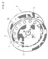
Figure 2 is a perspective view of the wheel structure ofFigure 1 ; -
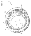
Figure 3 is a perspective view of a preferred embodiment of the wheel structure according to the invention, where said structure is made of steel plate; -
Figure 4 is an exploded perspective view of the wheel structure ofFigure 3 ; -
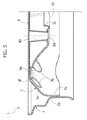
Figure 5 is a cross-sectional view at an enlarged scale of the wheel structure ofFigures 3 and4 in a plane containing the axis of the wheel; -
Figures 6, 7 , and8 are, respectively, a cross-sectional view, a side view, and a perspective view that show the deformations to which the wheel structure according to the invention is subject as it rolls, said deformations being exaggerated for reasons of clarity; and -
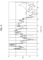
Figure 9 is a diagram that enables a comparison of the characteristics of noise of the wheel structure according to the invention with a wheel structure made of steel of the conventional type illustrated inFigure 1 , and with a wheel structure made of light alloy. - With reference to the drawings, both in the case of the conventional wheel of
Figures 1 and2 and in the case of the wheel according to the invention ofFigures 3-5 , thereference number 1 designates as a whole the motor-vehicle wheel structure, comprising awheel rim 2 made of stamped steel plate and amain wheel disk 3. - As may be seen in
Figure 5 for the wheel according to the invention, but also in the case of the conventional wheel ofFigures 1 and2 , themain disk 3 has a outercircumferential border 3a bent so as to define a cylindrical wall welded within an intermediatecylindrical wall 2a of therim 2. - The
main wheel disk 3 moreover presents, both in the case of the invention and in the conventional case, acentral portion 3b having acentral hub 3c for mounting on the corresponding part of a wheel support, and a plurality ofholes 3d for engagement of bolts for fixing the wheel to the wheel support. - Once again with reference to the
main wheel disk 3, both in the case of the invention (see in particularFigure 5 ) and in the conventional case, thecentral portion 3b of thedisk 3 is radiused with the outercircumferential border 3a by means of an intermediateannular portion 3e, which in the cross section illustrated inFigure 2 presents an arched profile, projecting outwards so as to have itsapex 3f substantially tangential to the outer end plane of therim 2. The aforesaid intermediateannular portion 3e moreover preferably has a plurality ofopenings 3g, which, in the example illustrated, have a circular shape, but may of course have any different shape and/or arrangement. - According to the invention, welded on the outer face of the
main disk 3 is an auxiliary disk 4 (seeFigures 3-5 ), also made of steel plate, presenting a substantially plane conformation and having itsouter border 4a welded to the projectingportion 3e of themain disk 3, substantially adjacent to itsapex 3f. As a result of said arrangement, theauxiliary disk 4 hence extends parallel to and at a distance from thecentral portion 3b of themain disk 3. - The
auxiliary disk 4 moreover integrates a plurality oftubular columns 4b, which, in the example illustrated, have a conical conformation tapering in the direction of thecentral portion 3b. Eachtubular column 4b extends co-axial to arespective hole 3d made in themain disk 3 and has its end opposite to thedisk 4 that is welded to thecentral portion 3b of themain disk 3. In this way, thecolumns 4b are able to stiffen considerably the box structure defined between the parallel and facing walls of thecentral portion 3b of themain disk 3 and theauxiliary disk 4. -
Figures 6-8 of the annexed drawings show, exaggerated for reasons of clarity, the deformations to which the wheel structure according to the invention is subject during use. The studies and tests conducted by the present applicant have shown that said deformations are considerably smaller than those to which a wheel structure made of steel of the type ofFigures 1 and2 , without theauxiliary disk 4, is subject and that they are substantially similar or in any case close to those to which a wheel structure without thedisk 4 but made of light alloy would be subject. Said result is highlighted in the diagram ofFigure 9 , which has been obtained by measuring the noise in the passenger compartment of the motor vehicle when it is travelling. The diagram shows the variation of the noise at the different frequencies for the wheel according to the invention (solid line), for a wheel made of steel of the conventional type illustrated inFigures 1 and2 (dashed line), and for a wheel without thedisk 4 but made of light alloy (dashed and dotted line). The diagram brings out clearly the considerable noise reduction that can be obtained in a wheel made of steel thanks to the adoption of the characteristics that form the subject of the present invention, particularly in certain frequency ranges. The diagram moreover shows how the noise of the wheel according to the invention is comparable to that of a wheel made of light alloy. - The outer face of the
auxiliary disk 4 can be configured and/or decorated and/or painted to bestow a given aesthetic pattern on the wheel structure. - Of course, without prejudice to the principle of the invention, the details of construction and the embodiments may vary widely with respect to what is described and illustrated herein purely by way of example, without thereby departing from the scope of the present invention.
- In particular, even though the invention has been illustrated with reference to an embodiment that envisages that the structure of the wheel is made of steel plate, by no means ruled out is the possibility of re-applying the concepts of the invention also to a wheel made of light alloy in order to increase the stiffness thereof as compared to the traditional configuration.
Claims (6)
- A motor-vehicle wheel structure, comprising a wheel rim (2) and a wheel disk (3) having a circumferential border (3a), which is bent and welded within the rim (2), said disk having a central portion (3b) with a circumferential series of holes (3d) for engagement of bolts for fixing the wheel to a wheel support, said central portion (3b) of the wheel disk (3) being radiused to the aforesaid outer circumferential border (3a) by an intermediate annular portion (3e) of the wheel disk having in cross section an arched conformation projecting outwards,
said wheel structure being characterized in that welded on the outer face of said wheel disk (3) is an auxiliary disk (4) having a substantially plane conformation, the outer border of which is welded to the main disk (3) substantially in a position corresponding to the apex (3f) of the aforesaid projecting annular portion (3e) in such a way as to extend parallel to and at a distance from the central portion (3b) of the main disk (3), said auxiliary disk (4) integrating tubular columns (4b) projecting from the inner face of the auxiliary disk (4) and having their ends welded to the central portion (3b) of the main disk (3) so that they are co-axial to the aforesaid holes (3d) for the fixing bolts. - The wheel structure according to Claim 1, characterized in that said intermediate annular portion (3e) of the main disk (3) has a plurality of openings (3g) set at the same angular distance apart from one another.
- The wheel structure according to Claim 1, characterized in that said tubular columns (4b) are conical and tapered in the direction of the central portion (3b) of the main disk (3).
- The wheel structure according to Claim 1, characterized in that the outer face of said auxiliary disk (4) is configured and/or decorated and/or painted to bestow a given aesthetic pattern on the wheel structure.
- The wheel structure according to Claim 1, characterized in that the rim (2), the main disk (3), and the auxiliary disk (4) are all made of steel plate.
- The wheel structure according to Claim 1, characterized in that the rim (2), the main disk (3), and the auxiliary disk (4) are all made of light alloy.
Priority Applications (4)
| Application Number | Priority Date | Filing Date | Title |
|---|---|---|---|
| EP08425747A EP2189300B1 (en) | 2008-11-24 | 2008-11-24 | Motor-vehicle wheel structure having a main disc and an auxiliary disc |
| AT08425747T ATE492410T1 (en) | 2008-11-24 | 2008-11-24 | STRUCTURE OF A VEHICLE WHEEL HAVING A MAIN AND AUXILIARY WHEEL DISC |
| DE602008004174T DE602008004174D1 (en) | 2008-11-24 | 2008-11-24 | Structure of a vehicle wheel having a main and Hilfsradscheibe |
| US12/547,925 US8038224B2 (en) | 2008-11-24 | 2009-08-26 | Motor-vehicle wheel structure having a main disk and an auxiliary disk |
Applications Claiming Priority (1)
| Application Number | Priority Date | Filing Date | Title |
|---|---|---|---|
| EP08425747A EP2189300B1 (en) | 2008-11-24 | 2008-11-24 | Motor-vehicle wheel structure having a main disc and an auxiliary disc |
Publications (2)
| Publication Number | Publication Date |
|---|---|
| EP2189300A1 true EP2189300A1 (en) | 2010-05-26 |
| EP2189300B1 EP2189300B1 (en) | 2010-12-22 |
Family
ID=40568706
Family Applications (1)
| Application Number | Title | Priority Date | Filing Date |
|---|---|---|---|
| EP08425747A Not-in-force EP2189300B1 (en) | 2008-11-24 | 2008-11-24 | Motor-vehicle wheel structure having a main disc and an auxiliary disc |
Country Status (4)
| Country | Link |
|---|---|
| US (1) | US8038224B2 (en) |
| EP (1) | EP2189300B1 (en) |
| AT (1) | ATE492410T1 (en) |
| DE (1) | DE602008004174D1 (en) |
Families Citing this family (1)
| Publication number | Priority date | Publication date | Assignee | Title |
|---|---|---|---|---|
| US20150210109A1 (en) * | 2012-06-28 | 2015-07-30 | Dr. Ing. H.C.F. Porsche Aktiengesellschaft | Motor vehicle wheel |
Citations (6)
| Publication number | Priority date | Publication date | Assignee | Title |
|---|---|---|---|---|
| GB453876A (en) * | 1935-03-16 | 1936-09-16 | Frederick William Baker | Improvements in or relating to vehicle wheels |
| FR845949A (en) * | 1937-11-18 | 1939-09-05 | Dunlop Sa | Improvements to wheels for vehicles and to the process for manufacturing these wheels |
| US3767267A (en) * | 1972-01-12 | 1973-10-23 | R Clement | Heavy duty wheel and wheel center |
| DE4027355A1 (en) * | 1989-08-31 | 1991-03-14 | Masakazu Hayashi | DOUBLE DISC STRUCTURE FOR LIGHT METAL VEHICLE WHEELS |
| DE19601778A1 (en) * | 1995-10-11 | 1997-04-17 | Porsche Ag | Wheel for a motor vehicle |
| DE10130450A1 (en) * | 2001-06-23 | 2003-01-09 | Erfurt Umformtechnik Gmbh | Spoked wheel with star-shaped bowl welded in rim below hump region has extra spoke crown between bowl and rim |
Family Cites Families (9)
| Publication number | Priority date | Publication date | Assignee | Title |
|---|---|---|---|---|
| US1399410A (en) * | 1921-12-06 | Frederick s | ||
| US1380925A (en) * | 1919-03-27 | 1921-06-07 | Detroit Pressed Steel Co | Vehicle-wheel |
| US1745973A (en) * | 1921-03-30 | 1930-02-04 | Albert B Welles | Disk wheel |
| US2257684A (en) * | 1939-08-24 | 1941-09-30 | French & Hecht Inc | Wheel structure |
| US4511183A (en) * | 1983-07-11 | 1985-04-16 | Mr. Gasket Company | Steel wheel with decorative cover |
| US4645267A (en) * | 1984-09-28 | 1987-02-24 | Weld Racing Enterprises, Inc. | Vehicle wheel having non-suspension wire spokes |
| US4659148A (en) * | 1985-09-23 | 1987-04-21 | Motor Wheel Corporation | Vehicle wheel construction |
| US5188429A (en) * | 1991-02-22 | 1993-02-23 | Kelsey-Hayes Company | Fabricated wheel having a radially inwardly extending disc face |
| DE59603215D1 (en) * | 1995-10-11 | 1999-11-04 | Porsche Ag | Wheel for a motor vehicle |
-
2008
- 2008-11-24 DE DE602008004174T patent/DE602008004174D1/en active Active
- 2008-11-24 EP EP08425747A patent/EP2189300B1/en not_active Not-in-force
- 2008-11-24 AT AT08425747T patent/ATE492410T1/en not_active IP Right Cessation
-
2009
- 2009-08-26 US US12/547,925 patent/US8038224B2/en not_active Expired - Fee Related
Patent Citations (6)
| Publication number | Priority date | Publication date | Assignee | Title |
|---|---|---|---|---|
| GB453876A (en) * | 1935-03-16 | 1936-09-16 | Frederick William Baker | Improvements in or relating to vehicle wheels |
| FR845949A (en) * | 1937-11-18 | 1939-09-05 | Dunlop Sa | Improvements to wheels for vehicles and to the process for manufacturing these wheels |
| US3767267A (en) * | 1972-01-12 | 1973-10-23 | R Clement | Heavy duty wheel and wheel center |
| DE4027355A1 (en) * | 1989-08-31 | 1991-03-14 | Masakazu Hayashi | DOUBLE DISC STRUCTURE FOR LIGHT METAL VEHICLE WHEELS |
| DE19601778A1 (en) * | 1995-10-11 | 1997-04-17 | Porsche Ag | Wheel for a motor vehicle |
| DE10130450A1 (en) * | 2001-06-23 | 2003-01-09 | Erfurt Umformtechnik Gmbh | Spoked wheel with star-shaped bowl welded in rim below hump region has extra spoke crown between bowl and rim |
Also Published As
| Publication number | Publication date |
|---|---|
| US20100127557A1 (en) | 2010-05-27 |
| US8038224B2 (en) | 2011-10-18 |
| ATE492410T1 (en) | 2011-01-15 |
| EP2189300B1 (en) | 2010-12-22 |
| DE602008004174D1 (en) | 2011-02-03 |
Similar Documents
| Publication | Publication Date | Title |
|---|---|---|
| EP2189299B1 (en) | Motor-vehicle wheel structure | |
| US8181685B2 (en) | Vehicle wheel | |
| US10717319B2 (en) | Vehicle wheel for passenger cars | |
| JP5223900B2 (en) | Vehicle bumper | |
| JP6125998B2 (en) | Wheel disc for vehicle | |
| JP5419989B2 (en) | Wheel disc for automobile | |
| JP2010132277A5 (en) | ||
| JP2012066691A (en) | Wheel for automobile | |
| US9555663B2 (en) | Automotive wheel with cavity between bolt holes in hub mounting section | |
| JP2019503932A5 (en) | Assembled vehicle wheel | |
| US6637828B2 (en) | Wheel construction, in particular for automobiles | |
| EP3795371B1 (en) | Vehicle wheel structure and resonator | |
| EP2189300B1 (en) | Motor-vehicle wheel structure having a main disc and an auxiliary disc | |
| US20060033380A1 (en) | Wheel for motor vehicle | |
| CN105835611B (en) | Light metal wheel for motor vehicles | |
| KR102656094B1 (en) | Assembled vehicle wheel with wheel disc with lightweight pockets | |
| JP2012158332A (en) | Method for assembling auxiliary air chamber member | |
| JP6466586B2 (en) | Automotive wheel | |
| JP6226006B2 (en) | Hub unit for vehicles | |
| WO2025126516A1 (en) | Tire set and tire wheel assembly | |
| JP2013060074A (en) | Vehicle hub unit | |
| JP2020079045A (en) | Vehicle wheel | |
| JP2020083021A (en) | Vehicular wheel |
Legal Events
| Date | Code | Title | Description |
|---|---|---|---|
| PUAI | Public reference made under article 153(3) epc to a published international application that has entered the european phase |
Free format text: ORIGINAL CODE: 0009012 |
|
| 17P | Request for examination filed |
Effective date: 20090818 |
|
| AK | Designated contracting states |
Kind code of ref document: A1 Designated state(s): AT BE BG CH CY CZ DE DK EE ES FI FR GB GR HR HU IE IS IT LI LT LU LV MC MT NL NO PL PT RO SE SI SK TR |
|
| AX | Request for extension of the european patent |
Extension state: AL BA MK RS |
|
| GRAP | Despatch of communication of intention to grant a patent |
Free format text: ORIGINAL CODE: EPIDOSNIGR1 |
|
| GRAS | Grant fee paid |
Free format text: ORIGINAL CODE: EPIDOSNIGR3 |
|
| GRAA | (expected) grant |
Free format text: ORIGINAL CODE: 0009210 |
|
| AK | Designated contracting states |
Kind code of ref document: B1 Designated state(s): AT BE BG CH CY CZ DE DK EE ES FI FR GB GR HR HU IE IS IT LI LT LU LV MC MT NL NO PL PT RO SE SI SK TR |
|
| REG | Reference to a national code |
Ref country code: GB Ref legal event code: FG4D |
|
| REG | Reference to a national code |
Ref country code: CH Ref legal event code: EP |
|
| REG | Reference to a national code |
Ref country code: IE Ref legal event code: FG4D |
|
| AKX | Designation fees paid |
Designated state(s): AT BE BG CH CY CZ DE DK EE ES FI FR GB GR HR HU IE IS IT LI LT LU LV MC MT NL NO PL PT RO SE SI SK TR |
|
| REF | Corresponds to: |
Ref document number: 602008004174 Country of ref document: DE Date of ref document: 20110203 Kind code of ref document: P |
|
| REG | Reference to a national code |
Ref country code: DE Ref legal event code: R096 Ref document number: 602008004174 Country of ref document: DE Effective date: 20110203 |
|
| REG | Reference to a national code |
Ref country code: NL Ref legal event code: VDEP Effective date: 20101222 |
|
| PG25 | Lapsed in a contracting state [announced via postgrant information from national office to epo] |
Ref country code: LT Free format text: LAPSE BECAUSE OF FAILURE TO SUBMIT A TRANSLATION OF THE DESCRIPTION OR TO PAY THE FEE WITHIN THE PRESCRIBED TIME-LIMIT Effective date: 20101222 |
|
| LTIE | Lt: invalidation of european patent or patent extension |
Effective date: 20101222 |
|
| PG25 | Lapsed in a contracting state [announced via postgrant information from national office to epo] |
Ref country code: CY Free format text: LAPSE BECAUSE OF FAILURE TO SUBMIT A TRANSLATION OF THE DESCRIPTION OR TO PAY THE FEE WITHIN THE PRESCRIBED TIME-LIMIT Effective date: 20101222 Ref country code: BG Free format text: LAPSE BECAUSE OF FAILURE TO SUBMIT A TRANSLATION OF THE DESCRIPTION OR TO PAY THE FEE WITHIN THE PRESCRIBED TIME-LIMIT Effective date: 20110322 Ref country code: SI Free format text: LAPSE BECAUSE OF FAILURE TO SUBMIT A TRANSLATION OF THE DESCRIPTION OR TO PAY THE FEE WITHIN THE PRESCRIBED TIME-LIMIT Effective date: 20101222 Ref country code: SE Free format text: LAPSE BECAUSE OF FAILURE TO SUBMIT A TRANSLATION OF THE DESCRIPTION OR TO PAY THE FEE WITHIN THE PRESCRIBED TIME-LIMIT Effective date: 20101222 Ref country code: HR Free format text: LAPSE BECAUSE OF FAILURE TO SUBMIT A TRANSLATION OF THE DESCRIPTION OR TO PAY THE FEE WITHIN THE PRESCRIBED TIME-LIMIT Effective date: 20101222 Ref country code: AT Free format text: LAPSE BECAUSE OF FAILURE TO SUBMIT A TRANSLATION OF THE DESCRIPTION OR TO PAY THE FEE WITHIN THE PRESCRIBED TIME-LIMIT Effective date: 20101222 Ref country code: LV Free format text: LAPSE BECAUSE OF FAILURE TO SUBMIT A TRANSLATION OF THE DESCRIPTION OR TO PAY THE FEE WITHIN THE PRESCRIBED TIME-LIMIT Effective date: 20101222 Ref country code: FI Free format text: LAPSE BECAUSE OF FAILURE TO SUBMIT A TRANSLATION OF THE DESCRIPTION OR TO PAY THE FEE WITHIN THE PRESCRIBED TIME-LIMIT Effective date: 20101222 |
|
| PG25 | Lapsed in a contracting state [announced via postgrant information from national office to epo] |
Ref country code: GR Free format text: LAPSE BECAUSE OF FAILURE TO SUBMIT A TRANSLATION OF THE DESCRIPTION OR TO PAY THE FEE WITHIN THE PRESCRIBED TIME-LIMIT Effective date: 20110323 Ref country code: NO Free format text: LAPSE BECAUSE OF FAILURE TO SUBMIT A TRANSLATION OF THE DESCRIPTION OR TO PAY THE FEE WITHIN THE PRESCRIBED TIME-LIMIT Effective date: 20110322 Ref country code: PT Free format text: LAPSE BECAUSE OF FAILURE TO SUBMIT A TRANSLATION OF THE DESCRIPTION OR TO PAY THE FEE WITHIN THE PRESCRIBED TIME-LIMIT Effective date: 20110422 Ref country code: ES Free format text: LAPSE BECAUSE OF FAILURE TO SUBMIT A TRANSLATION OF THE DESCRIPTION OR TO PAY THE FEE WITHIN THE PRESCRIBED TIME-LIMIT Effective date: 20110402 Ref country code: CZ Free format text: LAPSE BECAUSE OF FAILURE TO SUBMIT A TRANSLATION OF THE DESCRIPTION OR TO PAY THE FEE WITHIN THE PRESCRIBED TIME-LIMIT Effective date: 20101222 Ref country code: BE Free format text: LAPSE BECAUSE OF FAILURE TO SUBMIT A TRANSLATION OF THE DESCRIPTION OR TO PAY THE FEE WITHIN THE PRESCRIBED TIME-LIMIT Effective date: 20101222 Ref country code: IS Free format text: LAPSE BECAUSE OF FAILURE TO SUBMIT A TRANSLATION OF THE DESCRIPTION OR TO PAY THE FEE WITHIN THE PRESCRIBED TIME-LIMIT Effective date: 20110422 Ref country code: EE Free format text: LAPSE BECAUSE OF FAILURE TO SUBMIT A TRANSLATION OF THE DESCRIPTION OR TO PAY THE FEE WITHIN THE PRESCRIBED TIME-LIMIT Effective date: 20101222 |
|
| PG25 | Lapsed in a contracting state [announced via postgrant information from national office to epo] |
Ref country code: SK Free format text: LAPSE BECAUSE OF FAILURE TO SUBMIT A TRANSLATION OF THE DESCRIPTION OR TO PAY THE FEE WITHIN THE PRESCRIBED TIME-LIMIT Effective date: 20101222 Ref country code: PL Free format text: LAPSE BECAUSE OF FAILURE TO SUBMIT A TRANSLATION OF THE DESCRIPTION OR TO PAY THE FEE WITHIN THE PRESCRIBED TIME-LIMIT Effective date: 20101222 Ref country code: NL Free format text: LAPSE BECAUSE OF FAILURE TO SUBMIT A TRANSLATION OF THE DESCRIPTION OR TO PAY THE FEE WITHIN THE PRESCRIBED TIME-LIMIT Effective date: 20101222 |
|
| PLBE | No opposition filed within time limit |
Free format text: ORIGINAL CODE: 0009261 |
|
| STAA | Information on the status of an ep patent application or granted ep patent |
Free format text: STATUS: NO OPPOSITION FILED WITHIN TIME LIMIT |
|
| PG25 | Lapsed in a contracting state [announced via postgrant information from national office to epo] |
Ref country code: DK Free format text: LAPSE BECAUSE OF FAILURE TO SUBMIT A TRANSLATION OF THE DESCRIPTION OR TO PAY THE FEE WITHIN THE PRESCRIBED TIME-LIMIT Effective date: 20101222 |
|
| 26N | No opposition filed |
Effective date: 20110923 |
|
| REG | Reference to a national code |
Ref country code: DE Ref legal event code: R097 Ref document number: 602008004174 Country of ref document: DE Effective date: 20110923 |
|
| PG25 | Lapsed in a contracting state [announced via postgrant information from national office to epo] |
Ref country code: MC Free format text: LAPSE BECAUSE OF NON-PAYMENT OF DUE FEES Effective date: 20111130 |
|
| REG | Reference to a national code |
Ref country code: IE Ref legal event code: MM4A |
|
| PG25 | Lapsed in a contracting state [announced via postgrant information from national office to epo] |
Ref country code: IE Free format text: LAPSE BECAUSE OF NON-PAYMENT OF DUE FEES Effective date: 20111124 |
|
| PG25 | Lapsed in a contracting state [announced via postgrant information from national office to epo] |
Ref country code: MT Free format text: LAPSE BECAUSE OF FAILURE TO SUBMIT A TRANSLATION OF THE DESCRIPTION OR TO PAY THE FEE WITHIN THE PRESCRIBED TIME-LIMIT Effective date: 20101222 |
|
| PG25 | Lapsed in a contracting state [announced via postgrant information from national office to epo] |
Ref country code: LU Free format text: LAPSE BECAUSE OF NON-PAYMENT OF DUE FEES Effective date: 20111124 |
|
| REG | Reference to a national code |
Ref country code: CH Ref legal event code: PL |
|
| GBPC | Gb: european patent ceased through non-payment of renewal fee |
Effective date: 20121124 |
|
| PG25 | Lapsed in a contracting state [announced via postgrant information from national office to epo] |
Ref country code: LI Free format text: LAPSE BECAUSE OF NON-PAYMENT OF DUE FEES Effective date: 20121130 Ref country code: CH Free format text: LAPSE BECAUSE OF NON-PAYMENT OF DUE FEES Effective date: 20121130 |
|
| PG25 | Lapsed in a contracting state [announced via postgrant information from national office to epo] |
Ref country code: TR Free format text: LAPSE BECAUSE OF FAILURE TO SUBMIT A TRANSLATION OF THE DESCRIPTION OR TO PAY THE FEE WITHIN THE PRESCRIBED TIME-LIMIT Effective date: 20101222 |
|
| PG25 | Lapsed in a contracting state [announced via postgrant information from national office to epo] |
Ref country code: HU Free format text: LAPSE BECAUSE OF FAILURE TO SUBMIT A TRANSLATION OF THE DESCRIPTION OR TO PAY THE FEE WITHIN THE PRESCRIBED TIME-LIMIT Effective date: 20101222 |
|
| PG25 | Lapsed in a contracting state [announced via postgrant information from national office to epo] |
Ref country code: GB Free format text: LAPSE BECAUSE OF NON-PAYMENT OF DUE FEES Effective date: 20121124 |
|
| PGFP | Annual fee paid to national office [announced via postgrant information from national office to epo] |
Ref country code: IT Payment date: 20131111 Year of fee payment: 6 |
|
| PG25 | Lapsed in a contracting state [announced via postgrant information from national office to epo] |
Ref country code: RO Free format text: LAPSE BECAUSE OF FAILURE TO SUBMIT A TRANSLATION OF THE DESCRIPTION OR TO PAY THE FEE WITHIN THE PRESCRIBED TIME-LIMIT Effective date: 20101222 |
|
| PGFP | Annual fee paid to national office [announced via postgrant information from national office to epo] |
Ref country code: DE Payment date: 20141118 Year of fee payment: 7 Ref country code: FR Payment date: 20141110 Year of fee payment: 7 |
|
| PG25 | Lapsed in a contracting state [announced via postgrant information from national office to epo] |
Ref country code: IT Free format text: LAPSE BECAUSE OF NON-PAYMENT OF DUE FEES Effective date: 20141124 |
|
| REG | Reference to a national code |
Ref country code: DE Ref legal event code: R119 Ref document number: 602008004174 Country of ref document: DE |
|
| REG | Reference to a national code |
Ref country code: FR Ref legal event code: ST Effective date: 20160729 |
|
| PG25 | Lapsed in a contracting state [announced via postgrant information from national office to epo] |
Ref country code: DE Free format text: LAPSE BECAUSE OF NON-PAYMENT OF DUE FEES Effective date: 20160601 |
|
| PG25 | Lapsed in a contracting state [announced via postgrant information from national office to epo] |
Ref country code: FR Free format text: LAPSE BECAUSE OF NON-PAYMENT OF DUE FEES Effective date: 20151130 |