EP2189142A2 - Spring frame and spring body for support, for a mattress for example - Google Patents
Spring frame and spring body for support, for a mattress for example Download PDFInfo
- Publication number
- EP2189142A2 EP2189142A2 EP09014090A EP09014090A EP2189142A2 EP 2189142 A2 EP2189142 A2 EP 2189142A2 EP 09014090 A EP09014090 A EP 09014090A EP 09014090 A EP09014090 A EP 09014090A EP 2189142 A2 EP2189142 A2 EP 2189142A2
- Authority
- EP
- European Patent Office
- Prior art keywords
- spring
- spring body
- frame according
- spring frame
- elastic
- Prior art date
- Legal status (The legal status is an assumption and is not a legal conclusion. Google has not performed a legal analysis and makes no representation as to the accuracy of the status listed.)
- Withdrawn
Links
- 239000006260 foam Substances 0.000 claims abstract description 9
- 239000004033 plastic Substances 0.000 claims abstract description 5
- 229920003023 plastic Polymers 0.000 claims abstract description 5
- 238000009423 ventilation Methods 0.000 claims description 8
- 230000006835 compression Effects 0.000 claims description 6
- 238000007906 compression Methods 0.000 claims description 6
- 230000002093 peripheral effect Effects 0.000 claims description 6
- 230000008878 coupling Effects 0.000 claims description 3
- 238000010168 coupling process Methods 0.000 claims description 3
- 238000005859 coupling reaction Methods 0.000 claims description 3
- 238000005192 partition Methods 0.000 claims description 2
- 230000004323 axial length Effects 0.000 claims 1
- 238000007373 indentation Methods 0.000 claims 1
- 239000011796 hollow space material Substances 0.000 abstract 2
- 239000000463 material Substances 0.000 description 3
- 206010011985 Decubitus ulcer Diseases 0.000 description 2
- 229910000831 Steel Inorganic materials 0.000 description 2
- 238000004891 communication Methods 0.000 description 2
- 230000000694 effects Effects 0.000 description 2
- 239000013013 elastic material Substances 0.000 description 2
- 230000002787 reinforcement Effects 0.000 description 2
- 239000010959 steel Substances 0.000 description 2
- 208000004210 Pressure Ulcer Diseases 0.000 description 1
- 206010040954 Skin wrinkling Diseases 0.000 description 1
- 241000950638 Symphysodon discus Species 0.000 description 1
- 230000015572 biosynthetic process Effects 0.000 description 1
- 238000010276 construction Methods 0.000 description 1
- 238000013016 damping Methods 0.000 description 1
- 230000001934 delay Effects 0.000 description 1
- 238000006073 displacement reaction Methods 0.000 description 1
- 239000004744 fabric Substances 0.000 description 1
- 230000002349 favourable effect Effects 0.000 description 1
- HOQADATXFBOEGG-UHFFFAOYSA-N isofenphos Chemical compound CCOP(=S)(NC(C)C)OC1=CC=CC=C1C(=O)OC(C)C HOQADATXFBOEGG-UHFFFAOYSA-N 0.000 description 1
- 239000010985 leather Substances 0.000 description 1
- 238000000034 method Methods 0.000 description 1
- 230000000474 nursing effect Effects 0.000 description 1
- 239000002985 plastic film Substances 0.000 description 1
- 229920006255 plastic film Polymers 0.000 description 1
- 239000004814 polyurethane Substances 0.000 description 1
- 239000011148 porous material Substances 0.000 description 1
- 239000007787 solid Substances 0.000 description 1
- 239000013589 supplement Substances 0.000 description 1
- 239000000725 suspension Substances 0.000 description 1
- 229920001169 thermoplastic Polymers 0.000 description 1
- 239000004416 thermosoftening plastic Substances 0.000 description 1
- 239000011800 void material Substances 0.000 description 1
- 239000002759 woven fabric Substances 0.000 description 1
Images



Classifications
-
- A—HUMAN NECESSITIES
- A61—MEDICAL OR VETERINARY SCIENCE; HYGIENE
- A61G—TRANSPORT, PERSONAL CONVEYANCES, OR ACCOMMODATION SPECIALLY ADAPTED FOR PATIENTS OR DISABLED PERSONS; OPERATING TABLES OR CHAIRS; CHAIRS FOR DENTISTRY; FUNERAL DEVICES
- A61G7/00—Beds specially adapted for nursing; Devices for lifting patients or disabled persons
- A61G7/05—Parts, details or accessories of beds
- A61G7/057—Arrangements for preventing bed-sores or for supporting patients with burns, e.g. mattresses specially adapted therefor
- A61G7/0573—Arrangements for preventing bed-sores or for supporting patients with burns, e.g. mattresses specially adapted therefor with mattress frames having alternately movable parts
-
- A—HUMAN NECESSITIES
- A61—MEDICAL OR VETERINARY SCIENCE; HYGIENE
- A61G—TRANSPORT, PERSONAL CONVEYANCES, OR ACCOMMODATION SPECIALLY ADAPTED FOR PATIENTS OR DISABLED PERSONS; OPERATING TABLES OR CHAIRS; CHAIRS FOR DENTISTRY; FUNERAL DEVICES
- A61G2203/00—General characteristics of devices
- A61G2203/30—General characteristics of devices characterised by sensor means
- A61G2203/34—General characteristics of devices characterised by sensor means for pressure
-
- A—HUMAN NECESSITIES
- A61—MEDICAL OR VETERINARY SCIENCE; HYGIENE
- A61G—TRANSPORT, PERSONAL CONVEYANCES, OR ACCOMMODATION SPECIALLY ADAPTED FOR PATIENTS OR DISABLED PERSONS; OPERATING TABLES OR CHAIRS; CHAIRS FOR DENTISTRY; FUNERAL DEVICES
- A61G7/00—Beds specially adapted for nursing; Devices for lifting patients or disabled persons
- A61G7/05—Parts, details or accessories of beds
- A61G7/057—Arrangements for preventing bed-sores or for supporting patients with burns, e.g. mattresses specially adapted therefor
- A61G7/05715—Arrangements for preventing bed-sores or for supporting patients with burns, e.g. mattresses specially adapted therefor with modular blocks, or inserts, with layers of different material
Definitions
- the invention relates to a spring frame and a spring body for supporting z.
- a mattress especially for nursing beds and domestic beds, but also z.
- a cushion for upholstered furniture and motor vehicle seats or an unpadded edition for example, in light vehicle seats and training equipment for rehabilitation.
- beds and upholstered furniture have a spring frame with steel springs or a wooden slatted base on which a mattress, or a cushion rests.
- a spring frame with steel springs or a wooden slatted base on which a mattress, or a cushion rests.
- This is basically an air mattress.
- the invention is therefore based on the object to provide a spring frame available that allows a pneumatic, well-ventilated storage with a relatively flat structure.
- the above object is achieved in that are mounted on a supporting base pneumatic spring body having an elastic sheath and total or in groups on at least one flexible pressure distribution element are resilient, at least one spring body provided with a valve means gas inlet and / or - has outlet. On the pressure distribution element, a mattress, a cushion or an unpadded pad can be placed.
- the pneumatic spring body replace or supplement the steel springs or resilient wooden slats of the known spring frame, wherein in a particular case a large number of relatively small or different sized, pneumatic spring body can be provided which preferably contain air as gas.
- a pneumatic bearing which can optionally provide a uniform pressure distribution or different pressure zones. Both the spaces between the pneumatic spring bodies and via passageways can be provided for ventilation. Because of the advantageous pneumatic spring characteristics of the spring frame sufficient as a support a relatively thin, well ventilated mattress or padding, which can also have zones of different spring stiffness, such. B. in the EP 01 126 837 A described mattress.
- a pressure distribution element is selected in an embodiment, for. B. in the form of a strong knitted or woven fabric, leather or plastic film, which simultaneously meets the requirements of an unpadded edition, so that they can be omitted.
- Such spring frame are z. B. in vehicle seats and exercise equipment, especially in rehabilitation, used, possibly also with a treadmill as a pressure distribution element and / or edition.
- the elastic shell of the pneumatic spring body is preferably designed so that even in case of failure of the gas or air pressure a certain comfort due to the mechanical spring properties of the elastic sheaths is maintained.
- the spring properties can be selected by selecting the material, eg. As polyurethane (PU) or other suitable thermoplastic, different wall thicknesses, the design of the elastic shell, z. B. in the form of a cylinder or truncated cone with or without folding, affect the void volume and the nature of the valve device.
- a connecting line between the cavities of certain spring bodies or groups of spring bodies increases the compressed gas volume under load of a spring body and leads under otherwise identical conditions to a flatter spring characteristic. Such a characteristic is usually perceived as pleasant.
- Throttles or throttle valves in the valve means of the pneumatic spring body can be provided when the pneumatic spring body to respond with delay to load changes.
- Check valves are used to automatically replenish air leaks when the elastic sheath of a pneumatic spring body expands again after loading.
- the new spring frame is also suitable for active control of the spring properties, at least part of the pneumatic spring body.
- they can be connected to a common pressure line and common signal and control lines and provided with pressure sensors.
- Controllable inlet and vent valves are expediently actuated by piezoelectric elements and can be controlled by a processor via a bus system.
- Such a control system can accommodate the varying weight of patients and respond very quickly to movements of a person in bed.
- An especially suitable for use in the spring frame according to the invention pneumatic spring body which is mainly intended for large loads, has an elastic sheath in the outer shape of one or more superimposed in the loading direction superimposed, preferably round cushions, each with the inner cavities adjacent Cushion are delimited by a single or multi-layer partition, but communicate via a connection opening.
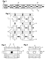
- Fig. 1 one of several rows of pneumatic spring body 10 is shown, one of which in 3 and 4 shown in larger scale as a single item.
- the spring body 10 are fixed on a base 12 in the form of a plate, batten or spring bar and connected to each other at the top by a highly flexible pressure distribution element 14.
- the spring body 10 are connected to the adjacent spring bodies in the series and in each case also with the adjacent spring bodies of the adjacent rows by connecting lines 16.
- the air or other gas containing inner cavities of the spring body 10 communicate with each other.
- the pressure increase is much lower and the spring characteristic correspondingly flatter than in an arrangement of spring bodies which are not connected to each other via connecting lines 16.
- the spring body 10 can individually, in groups or in total, possibly including connecting lines 16, produced in two halves and then welded in a lying transverse to the central longitudinal axis, middle part plane.
- valve devices may be arranged, for. As throttles or throttle valves to delay under load of a spring body 10, the displacement of air from the cavity.
- pressure relief valves could be used at individual points or generally.
- controllable valves can be used, which, for. B. be programmatically controlled so that depending on the load distribution and thus recognizable position or sitting position of a person closed certain spring body and thereby hardened and brought by opening the valve connecting them and possibly vented or slightly more pressurized air.
- each individual or defined groups of spring bodies 10 may preferably also be such that all the spring body 10 in series to a bypassed at all compressed air line in each case via a z.
- B. actuatable by piezoelectric elements control valve can be connected, wherein the control is done by a bus system and the control valves in series connecting signal line. To this Way can be set in each of the spring body 10, a certain pressure and thus a certain spring characteristic.
- the z. B. cooperate with a projection in the upper region of the shell or a fixed portion of the flexible pressure distribution element 14, limit the travel.
- spring bodies 10 Before discussing further forms of spring bodies 10 below, it should be pointed out that it is expedient to fix the spring bodies 10 at least relative to one another, if possible also relative to the base 12 and the pressure distributor element 14.
- the in Fig. 1 to 4 shown spring body formed both on its underside and on its upper side with two depressions 21, in which on the base 12 and on the flexible pressure distribution element 14 mounted, nozzle-shaped projections engage.
- the connecting lines 16, despite existing flexibility and tensile and compressive load in the longitudinal direction can be made relatively rigid, so that they also represent mechanically effective couplings between the spring bodies 10.
- spring body 10 extends through the middle of its inner cavity through a ventilation duct 22 which has at the bottom and top connection to through holes in the base 12 and in the pressure distribution element 14.
- a ventilation duct 22 which has at the bottom and top connection to through holes in the base 12 and in the pressure distribution element 14.
- the ventilation duct 22 with a concertina-like Folded to be equally adaptable in length to the same extent.
- the execution of the spring body 10 after Fig. 6 is similar to the post Fig. 5 but formed with a horizontal fold, radially inner wall 24 does not form a ventilation channel, but a compression spring which enhances the spring action of the outer shell of the spring body.
- a second pneumatic spring can be formed. It is considered advantageous that the proposed spring body 10 act not only due to the enclosed gas volume as a gas spring, but also as a mechanical spring due to the elastic properties of the correspondingly shaped shell.
- the mechanical spring properties are preferably dimensioned so that even in case of failure of the internal pressure due to the mechanical spring action a tolerable minimum comfort is maintained.
- a spring-loaded expansion vessel 26 connected to the interior of the spring body 10 is shown. Also in this way can be increased when the spring body 10 compressed gas volume.
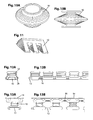
- the embodiment according to Fig. 7A , B is a spring body 10 having a substantially tapered outer shape, wherein the peripheral wall is formed with annular circumferential, horizontal folds or waves.
- a hollow body is particularly easy to compress under vertical load, so that the spring properties are determined in this case essentially by the air pressure in the closed interior.
- Fig. 8 The parallel, substantially horizontal folds of the outer shell extend undulating around the circumference. This improves the tilting rigidity.
- the embodiment aims in the same direction Fig. 9A , B, where the cylindrical shell wall of the spring body 10 shown there is formed with a plurality of radially outwardly facing, regularly arranged and equal sized pyramid tips.
- Fig. 10A , B proved, in which the sheath of the spring body 10 has approximately the shape of a disc and is provided to influence the spring characteristics on both sides around with radially extending depressions, optionally with reduced thickness.
- the spring body 10 according to Fig. 11 designed by uneven formation of its likewise provided with a folding envelope so that its upper part with respect to its lower part with increasing pressurization and under load performs a pivoting movement.
- z. B a peripheral edge lowered or raised.
- Fig. 12A B shows a series of spring bodies 10, which sit with their lower portion astride a serving as a base 12 bar and each extending through a transverse to the bar, in cross-section approximately C-shaped bracket 28, which the underside of the bar and Spring body 10 surrounds and engages in depressions in opposite side walls of the shell, are reliably held on the bar.
- the connection lines 16 extend here between the lower portions of the spring body 10. To simplify the drawing, the flexible pressure distribution element 14 and its connection with the top of the spring body 10 has been omitted.
- FIG. 13A B is another series of pneumatic spring body shown sitting next to each other firmly on a serving as a base 12 bar, but in this case are connected in the upper regions by connecting lines 16.
- the spring bodies 10 are fixed at the top and bottom relative to one another and do not necessarily need to be engaged with the flexible pressure distribution element 14. This is just as shown, placed on projections on the top of the spring body 10.
- the lower portion of the spring body 10 is shaped so that it surrounds the marginal edges of the bar 12 and firmly clamps the bar 12 upon pressure of the inner cavity.
- the lower part of the spring body 10 could be formed by a solid clamp, which can clamp the strip 12 by inherent elasticity and is firmly and tightly connected to the bellows of the pressurizable gas pressure on the top.
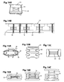
- Fig. 14A B is different from the one after Fig. 13A B, characterized in that the lower portions of the series of spring bodies 10 form a continuous tube 30 which engages over its entire length serving as a base 12 bar at its longitudinal edges and clamps.
- the inner cavity of the tube 30 is in communication with the immediately molded accordion-like sheaths of the spring body 10.
- Their connection to the flexible pressure distribution element 14 may, for. B. as in the execution Fig. 1 be designed.
- FIG. 10 Another design feature for a variety of juxtaposed spring bodies 10 may be that preferably tabs are integrally formed in the head or foot area, the z. B. holes and matching hooks for direct connection of adjacent spring body 10 or by fastening means z. B. are to be connected in the manner of screws or rivets.
- the tilting of the spring body can alternatively or additionally be prevented by the introduction of foam plastic in the interstices, in addition, a damping of the suspension can be achieved.
- the inner cavity except air or another gas may contain an open-cell foam body made of elastic material. This supports the mechanical spring action of the shell and delays the compression of the escape of the air contained in the pores, so has a similar effect as a throttle valve.
- the flexible envelope wall can also be combined on the outside with at least one elastic support body 32 which is compressible under load.
- He can z. B. have the shape of a round in cross-section, oval or rectangular ring, which sits in an outer annular groove of the shell wall of the spring body 10. In this way, one obtains a spring element 10, in which the function of the flexibility concentrated on the shell wall and the function of the mechanical spring action on the or the support body 32.
- Fig. 15A shows such a spring body 10 with support body 32.
- the flexible sheath connects a rigid upper part 34 and a rigid lower part 36. Both are formed on their outside with recesses for positive connection with the base 12 and with the flexible pressure distribution element 14.
- the upper and lower parts 34, 36 may consist of an elastic material and be provided with radial slots in the radially outer regions. Under load, the radial fingers formed thereby can yield axially and spring back. It is understood that such a shell-shaped lower part 36 and possibly also a corresponding upper part 34 also in a spring body 10 according to Fig. 7A , B can be used. The same applies to the execution after Fig. 15B with two annular support bodies 32.
- an elastic support body 32 surrounds the enveloping wall of a spring body 10 provided with horizontal folds.
- the latter can z. B. may be foamed in the existing elastic foam support body 32.
- the support body 32 is compressed as well as the flexible shell wall, which limits the inner cavity of the spring body 10.
- Fig. 16A , B, C shown surrounds a tubular, provided with cavities, made of elastic foam support body 32 the accordion-like folded spring body 10 without intervening between the folds of the shell wall.
- the upper and lower parts of the spring body 10 each have a larger diameter than the middle, folded part.
- the cylindrical support body 32 is located axially between the upper and lower part.
- the folded center region expands and the top raises accordingly Fig. 16C from the support body 32.
- With increasingly stronger load of the spring body 10 then comes the upper part according to Fig. 16B on the support body 32 to the plant, and then this is also compressed, as in Fig. 16A shown.
- FIG. 17 an embodiment in which a group of pneumatic spring bodies 10 is foamed into a mattress 37.
- the mattress can also assume the function of the pressure distribution element, so that under favorable conditions, only a thin mattress or a thin cushion needs to be placed or glued onto the mattress 37 containing the pneumatic spring body 10. If necessary, but also a pressure distribution element 14 can be inserted.
- the execution after Fig. 18 only differs from the after Fig. 17 in that the group of pneumatic spring bodies 10 are inserted into corresponding recesses, which also take into account the connecting lines 16, in the mattress 37.
- the foam surrounding the spring body 10 of the mattress 37 dampens any vibrations.
- the pressure distribution element 14 may be a highly flexible plate, but then not usually well suited for positive connection with the spring body. In addition, it must also have as many air vents 41 with regard to ventilation. It is therefore recommended As a rule, the pressure distribution element 14 of a plurality of small, in each case stable and provided with sufficient air passages 41 parts mosaic-like, wherein the in FIGS. 19 and 20 38, plate-shaped parts are connected by articulated and / or flexible intermediate parts 40.
- the intermediate part may consist of a two plate-shaped parts 38 connecting hinge pin. More mobility provide intermediate parts 40 with two ball joint-like recesses into which spherical projections on the plate-shaped parts 38 are latched.
- kinematic reversal and intermediate parts 40 can engage with spherical ends in spherical shell-shaped recesses in the plates 38.
- Fig. 20 shows a preferred embodiment in which the rectangular plate-shaped parts 38 in rows and columns next to each other and then four or at the edges of two adjacent plate-shaped parts 38 at the corner where they meet, are connected by a flexible intermediate part 40, the z , B. engages with pin-shaped projections in holes 43 in the adjacent corner regions of the plate-shaped parts 38.
- the intermediate parts 40 may be provided with air passages and mounted on the top or bottom of the plate-shaped parts 38.
- Fig. 20 shows different versions.
- the embodiment according to Fig. 21 shows a spring frame, similar to the embodiments according to Fig. 13 and 14 is constructed. Since the spring body 10 are connected to each other in the upper region by connecting lines 16, the lower, tubular portion 30 may be separated from the inner cavity of the spring body 10 and its application of compressed air only serve to firmly clamp the base bar 12.
- a special feature of the embodiment according to Fig. 21 is that in several places a pneumatic height adjustment 42 is available for the base, with a Pressure beaufschlagbares lifting element 44 and the stroke limiting stop 20 has.
- the lifting element 44 may have a similar structure as the spring body 10th
- Fig. 22 shows one opposite Fig. 21 modified, pneumatic device for adjusting the height of the base 12 on a larger scale.
- the base 12 rests at a plurality of locations on each of a pneumatic lifting element 46 and is raised when it is pressurized.
- An upper lifting element 48 arranged above the lower lifting element 46 serves to clamp the base 12.
- the lower and the upper lifting elements 46, 48 may be accommodated in a common holder 47. They could also be used as a pneumatic spring body 10 of a spring frame, especially at high loads, because their shell is not simply a bellows, but consists of superimposed, tight and tightly interconnected, discus or pillow-shaped shells whose interiors on the outside sealed communication openings 49 communicate in the adjacent walls. These prevent buckling of the enveloping wall over its entire height, even if the superimposed hulls are of different sizes and / or have different cross sections. It therefore requires no outer rings or other reinforcements to prevent bulging.
- pneumatic lifting elements also serve to put the base 12 in controlled vibration.
- a lower lifting element 50 and an upper lifting element 52 act by alternately pressurized vibrating on a pivotally connected to the holder and the base drive member 53, the up and out pivotal movement is transmitted via an articulated coupling to the base 12.
- the shape of the Lifting elements 50, 52 is suitably chosen so that its movable end moves arcuately.
- both the spring body 10 shown and described only as an example as well as the base 12 and the pressure distribution elements 14 can be further modified many times, but the functions highlighted here remain preserved. The same applies to the control of the internal pressure of the spring body 10 and lifting elements 44, 46, 48, 50, 52. So these z. B. in addition to a vacuum or vacuum line to be connected to accelerate a lowering process.
Landscapes
- Health & Medical Sciences (AREA)
- Nursing (AREA)
- Life Sciences & Earth Sciences (AREA)
- Animal Behavior & Ethology (AREA)
- General Health & Medical Sciences (AREA)
- Public Health (AREA)
- Veterinary Medicine (AREA)
- Mattresses And Other Support Structures For Chairs And Beds (AREA)
- Invalid Beds And Related Equipment (AREA)
Abstract
Description
Die Erfindung betrifft einen Federrahmen und einen Federkörper zur Abstützung z. B. einer Matratze, insbesondere für Pflegebetten und häusliche Betten, aber auch z. B. eines Polsters bei Polstermöbeln und Kraftfahrzeugsitzen oder einer ungepolsterten Auflage, beispielsweise bei leichten Fahrzeugsitzen und Trainingsgeräten für die Rehabilitation.The invention relates to a spring frame and a spring body for supporting z. As a mattress, especially for nursing beds and domestic beds, but also z. As a cushion for upholstered furniture and motor vehicle seats or an unpadded edition, for example, in light vehicle seats and training equipment for rehabilitation.
Üblicherweise haben Betten und Polstermöbel einen Federrahmen mit Stahlfedern oder einem Holzlattenrost, auf dem eine Matratze, bzw. ein Polster ruht. Um bei bettlägerigen Patienten einem Wundliegen vorzubeugen und generell eine gleichmäßigere Druckverteilung zu erreichen wird auf die Matratze noch eine Dekubitus-Auflage gelegt. Dabei handelt es sich im Prinzip um eine Luftmatratze. Nachteilig sind bei einer solchen Lagerung der hohe Aufbau und die schlechte Durchlüftung.Usually, beds and upholstered furniture have a spring frame with steel springs or a wooden slatted base on which a mattress, or a cushion rests. In bedridden patients to prevent bedsores and generally to achieve a more uniform pressure distribution is placed on the mattress even a decubitus pad. This is basically an air mattress. The disadvantage of such a storage of high construction and poor ventilation.
Der Erfindung liegt deshalb die Aufgabe zugrunde, einen Federrahmen zur Verfügung zu stellen, der eine pneumatische, gut durchlüftbare Lagerung mit einem verhältnismäßig flachen Aufbau gestattet.The invention is therefore based on the object to provide a spring frame available that allows a pneumatic, well-ventilated storage with a relatively flat structure.
Vorstehende Aufgabe wird erfindungsgemäß dadurch gelöst, dass auf einer tragenden Basis pneumatische Federkörper gelagert sind, die eine elastische Hülle haben und insgesamt oder in Gruppen über wenigstens ein flexibles Druckverteilerelement belastbar sind, wobei mindestens ein Federkörper einen mit einer Ventileinrichtung versehenen Gasein- und/oder -auslass aufweist. Auf das Druckverteilerelement kann eine Matratze, ein Polster oder eine ungepolsterte Auflage aufgelegt werden.The above object is achieved in that are mounted on a supporting base pneumatic spring body having an elastic sheath and total or in groups on at least one flexible pressure distribution element are resilient, at least one spring body provided with a valve means gas inlet and / or - has outlet. On the pressure distribution element, a mattress, a cushion or an unpadded pad can be placed.
Bei der Erfindung ersetzen oder ergänzen die pneumatischen Federkörper die Stahlfedern oder federnden Holzlatten der bekannten Federrahmen, wobei im Einzelfall eine große Zahl verhältnismäßig kleiner oder unterschiedlich großer, pneumatischer Federkörper vorgesehen sein kann, die als Gas vorzugsweise Luft enthalten. Damit ist bereits mit den die Matratze oder das Polster tragenden, elastischen Elementen eine pneumatische Lagerung realisiert, die wahlweise eine gleichmäßige Druckverteilung oder unterschiedliche Druckzonen bieten kann. Sowohl über die Zwischenräume zwischen den pneumatischen Federkörpern als auch über Durchgangskanäle kann für Durchlüftung gesorgt werden. Wegen der vorteilhaften pneumatischen Federeigenschaften des Federrahmens genügt als Auflage eine verhältnismäßig dünne, gut durchlüftbare Matratze oder Polsterung, die auch Zonen unterschiedlicher Federsteifigkeit haben kann, wie z. B. die in der
Die elastische Hülle der pneumatischen Federkörper wird vorzugsweise so ausgelegt, dass selbst bei Ausfall des Gas- bzw. Luftdrucks ein bestimmter Komfort aufgrund der mechanischen Federeigenschaften der elastischen Hüllen gewahrt bleibt. Die Federeigenschaften lassen sich durch Auswahl des Materials, z. B. Polyurethan (PU) oder ein anderer geeigneter Thermoplast, unterschiedliche Wandstärken, die Gestaltung der elastischen Hülle, z. B. in Form eines Zylinders oder Kegelstumpfs mit oder ohne Faltung, das Hohlraumvolumen und die Art der Ventileinrichtung beeinflussen.The elastic shell of the pneumatic spring body is preferably designed so that even in case of failure of the gas or air pressure a certain comfort due to the mechanical spring properties of the elastic sheaths is maintained. The spring properties can be selected by selecting the material, eg. As polyurethane (PU) or other suitable thermoplastic, different wall thicknesses, the design of the elastic shell, z. B. in the form of a cylinder or truncated cone with or without folding, affect the void volume and the nature of the valve device.
Eine Verbindungsleitung zwischen den Hohlräumen bestimmter Federkörper oder Gruppen von Federkörpern vergrößert das bei Belastung eines Federkörpers komprimierte Gasvolumen und führt unter sonst gleichen Bedingungen zu einer flacheren Federkennlinie. Eine solche Charakteristik wird meistens als angenehm empfunden. Drosseln oder Drosselventile in den Ventileinrichtungen der pneumatischen Federkörper können vorgesehen werden, wenn die pneumatischen Federkörper mit Verzögerung auf Belastungsänderungen reagieren sollen. Rückschlagventile werden verwendet, um Luftverluste selbsttätig wieder aufzufüllen, wenn sich die elastische Hülle eines pneumatischen Federkörpers nach einer Belastung wieder ausdehnt.A connecting line between the cavities of certain spring bodies or groups of spring bodies increases the compressed gas volume under load of a spring body and leads under otherwise identical conditions to a flatter spring characteristic. Such a characteristic is usually perceived as pleasant. Throttles or throttle valves in the valve means of the pneumatic spring body can be provided when the pneumatic spring body to respond with delay to load changes. Check valves are used to automatically replenish air leaks when the elastic sheath of a pneumatic spring body expands again after loading.
Der neue Federrahmen eignet sich auch für eine aktive Steuerung der Federeigenschaften, wenigstens eines Teils der pneumatischen Federkörper. Sie können zu diesem Zweck an eine gemeinsame Druckleitung und gemeinsame Signal- und Steuerleitungen angeschlossen und mit Drucksensoren versehen sein. Steuerbare Einlass- und Entlüftungsventile sind zweckmäßigerweise durch Piezoelemente betätigbar und durch einen Prozessor über ein Bus-System ansteuerbar. Ein derartiges Steuersystem kann das unterschiedliche Gewicht von Patienten berücksichtigen und auf Bewegungen einer im Bett liegenden Person sehr schnell reagieren.The new spring frame is also suitable for active control of the spring properties, at least part of the pneumatic spring body. For this purpose they can be connected to a common pressure line and common signal and control lines and provided with pressure sensors. Controllable inlet and vent valves are expediently actuated by piezoelectric elements and can be controlled by a processor via a bus system. Such a control system can accommodate the varying weight of patients and respond very quickly to movements of a person in bed.
Ein insbesondere zur Verwendung bei dem erfindungsgemäßen Federrahmen geeigneter pneumatischer Federkörper, der vor allem für große Belastungen vorgesehen ist, hat eine elastische Hülle in der äußeren Form eines oder mehrerer in Belastungsrichtung übereinander liegend angeordneter, vorzugsweise runder Kissen, wobei jeweils die inneren Hohlräume benachbarter Kissen durch eine ein- oder mehrlagige Zwischenwand abgegrenzt sind, aber über eine Verbindungsöffnung kommunizieren.An especially suitable for use in the spring frame according to the invention pneumatic spring body, which is mainly intended for large loads, has an elastic sheath in the outer shape of one or more superimposed in the loading direction superimposed, preferably round cushions, each with the inner cavities adjacent Cushion are delimited by a single or multi-layer partition, but communicate via a connection opening.
Nachstehend werden Ausführungsbeispiele pneumatischer Federkörper und der mit ihnen zusammenwirkenden Teile anhand der Zeichnung näher erläutert. Es zeigen:
- Fig. 1
- eine Seitenansicht einer Reihe pneumatischer Federkörper, die im Federrahmen zwischen einer die Basis bildenden Platte oder Federleiste und einem flexiblen Druckverteilerelement eingesetzt sind;
- Fig. 2
- eine Draufsicht auf mehrerer miteinander verbundene, anders als in
Fig. 1 gestaltete, pneumatische Federkörper; - Fig. 3
- eine Seitenansicht eines der Federkörper nach
Fig. 1 ; - Fig. 4
- eine um 90° versetzte Seitenansicht des Federkörpers nach
Fig. 3 ; - Fig. 5
- eine schematische Seitenansicht eines pneumatischen Federkörpers mit einer zentralen Belüftungsleitung;
- Fig. 6
- einen vereinfachten Längsschnitt eines pneumatischen Federkörpers mit einem radial innen durch eine zweite Mantelwand begrenzten, ringförmigen, mit Luft beaufschlagbaren Hohlraum;
- Fig. 7A, B
- Längsschnitte eines kegelig mit Stufen ausgebildeten, pneumatischen Federkörpers im entspannten bzw. komprimierten Zustand;
- Fig. 8
- eine Seitenansicht eines mit umlaufenden, gekrümmten Falten versehenen Federkörpers;
- Fig. 9A, B
- eine Seitenansicht und eine perspektivische Ansicht eines weiteren Federkörpers, dessen Hülle mit einer Vielzahl von radial ausgerichteten Pyramidenspitzen geformt ist;
- Fig. 10A, B
- eine perspektivische Ansicht und eine Seitenansicht einer besonders stabilen Ausführungsform eines pneumatischen Federkörpers;
- Fig. 11
- eine Seitenansicht eines pneumatischen Federkörpers, der bei Druckänderungen eine Schwenkbewegung ausführt;
- Fig. 12A, B
- zwei um 90° versetzte Seitenansichten einer Reihe von im Vergleich zu
Fig. 1 modifizierten Federkörpern; - Fig. 13A, B
- nochmals eine Reihe von pneumatischen Federkörpern, die durch Verbindungsleitungen miteinander verbunden sind, in zwei um 90° versetzten Seitenansichten;
- Fig. 14A, B
- um 90° gedrehte Seitenansichten eines schlauchförmig länglichen Federkörpers mit einer Reihe von Ausstülpungen;
- Fig. 15A,B,C
- verschiedene Ausführungsvarianten von pneumatischen Federkörpern, bei denen die mechanische Federelastizität der Hülle durch mit ihr verbundene elastomere Stützkörper verstärkt ist;
- Fig. 16A,B,C
- Seitenansichten eines in drei Kompressionsstadien gezeigten Federkörpers mit einem nur bei starker Kompression zur Wirkung kommenden, ringförmigen elastomeren Stützkörper;
- Fig. 17
- einen Querschnitt mehrerer in eine Matratze eingeschäumter, durch Verbindungsleitungen miteinander verbundener pneumatischer Federkörper;
- Fig. 18
- eine Gruppe von vier miteinander zu verbindenden pneumatischen Federkörpern, die in entsprechende Aussparungen in einer Matratze eingesetzt sind;
- Fig. 19
- einen Längsschnitt durch ein aus Einzelteilen sowie flexiblen und/oder gelenkigen Verbindungssteilen bestehendes Druckverteilerelement;
- Fig. 20
- eine Draufsicht auf mehrere plattenförmige Einzelteile eines Druckverteilerelements, die durch flexible und/oder gelenkige Verbindungsteile miteinander verbunden sind;
- Fig. 21
- in Seitensicht eine Reihe pneumatischer Federkörper ähnlich
Fig. 14a, b in Verbindung mit einer pneumatischen Höhenverstellung der die Federkörper tragenden Basis; - Fig. 22
- einen senkrechten Schnitt durch eine abgewandelte pneumatische Höhenverstellung der Basis und
- Fig. 23
- einen senkrechten Querschnitt einer pneumatischen Einrichtung zur Erzeugung von Vibrationen der die pneumatischen Federkörper tragenden Basis.
- Fig. 1
- a side view of a series of pneumatic spring body, which are inserted in the spring frame between a base forming the plate or spring bar and a flexible pressure distribution element;
- Fig. 2
- a top view of several interconnected, unlike in
Fig. 1 designed, pneumatic spring body; - Fig. 3
- a side view of the spring body after
Fig. 1 ; - Fig. 4
- a 90 ° offset side view of the spring body after
Fig. 3 ; - Fig. 5
- a schematic side view of a pneumatic spring body with a central ventilation duct;
- Fig. 6
- a simplified longitudinal section of a pneumatic spring body with a radially inwardly bounded by a second jacket wall, annular, can be acted upon with air cavity;
- Fig. 7A, B
- Longitudinal sections of a conically formed with steps, pneumatic spring body in the relaxed or compressed state;
- Fig. 8
- a side view of a provided with circumferential, curved folds spring body;
- Fig. 9A, B
- a side view and a perspective view of another spring body whose shell is formed with a plurality of radially oriented pyramid tips;
- Fig. 10A, B
- a perspective view and a side view of a particularly stable embodiment of a pneumatic spring body;
- Fig. 11
- a side view of a pneumatic spring body, which performs a pivotal movement when pressure changes;
- Fig. 12A, B
- Two 90 ° offset side views of a series of compared to
Fig. 1 modified spring bodies; - Fig. 13A, B
- again a series of pneumatic spring bodies, which are connected by connecting lines, in two offset by 90 ° side views;
- Fig. 14A, B
- rotated 90 ° side views of a tubular elongated spring body with a series of protuberances;
- Fig. 15A, B, C
- various embodiments of pneumatic spring bodies, in which the mechanical resilience of the shell is reinforced by her affiliated elastomeric support body;
- Fig. 16A, B, C
- Side views of a spring body shown in three stages of compression with a coming into effect only in strong compression, annular elastomeric support body;
- Fig. 17
- a cross section of several foamed in a mattress, interconnected by connecting lines pneumatic spring body;
- Fig. 18
- a group of four pneumatic spring bodies to be connected to each other, which are inserted into corresponding recesses in a mattress;
- Fig. 19
- a longitudinal section through an existing of individual parts and flexible and / or articulated connecting parts pressure distribution element;
- Fig. 20
- a plan view of a plurality of plate-shaped items of a pressure distribution element, which are interconnected by flexible and / or articulated connecting parts;
- Fig. 21
- similar in side view a series of pneumatic spring body
Fig. 14a, b in conjunction with a pneumatic height adjustment of the base supporting the spring body; - Fig. 22
- a vertical section through a modified pneumatic height adjustment of the base and
- Fig. 23
- a vertical cross section of a pneumatic device for generating vibrations of the base supporting the pneumatic spring body.
In
Die Federkörper 10 können einzeln, gruppenweise oder insgesamt, ggf. einschließlich Verbindungsleitungen 16, in zwei Hälften unterteilt produziert und dann in einer quer zur Mittellängsachse liegenden, mittleren Teilebene verschweißt werden.The
In den Verbindungsleitungen 16 oder den Anschlussstutzen 18 für diese können Ventileinrichtungen angeordnet sein, z. B. Drosseln oder Drosselventile, um bei Belastung eines Federkörpers 10 die Verdrängung von Luft aus dessen Hohlraum kontrolliert zu verzögern. Alternativ oder zusätzlich könnten an einzelnen Stellen oder generell auch Überdruckventile eingesetzt sein. In Verbindung mit Drucksensoren, die den Innendruck in den einzelnen Federkörpern 10 oder in bestimmten Gruppen von Federkörpern messen, können auch steuerbare Ventile zum Einsatz kommen, welche z. B. derart programmgesteuert werden, dass je nach Lastverteilung und daraus erkennbarer Lage oder Sitzposition einer Person bestimmte Federkörper abgesperrt und dadurch verhärtet und andere durch Öffnen der sie verbindenden Ventile in Verbindung gebracht und ggf. entlüftet oder etwas stärker mit Druckluft beaufschlagt werden.In the connecting
Die Steuerung jedes einzelnen oder definierter Gruppen von Federkörpern 10 kann vorzugsweise auch so erfolgen, dass sämtliche Federkörper 10 in Serie an eine an allen vorbeigeführte Druckluftleitung jeweils über ein z. B. durch Piezoelemente betätigbares Steuerventil anschließbar sind, wobei die Ansteuerung durch ein Bus-System und eine die Steuerventile in Serie verbindende Signalleitung geschieht. Auf diese Weise kann in jedem der Federkörper 10 ein bestimmter Druck und damit eine bestimmte Federkennlinie eingestellt werden.The control of each individual or defined groups of
Wie in
Je nach Anwendung z. B. in Kinderbetten, Betten für Dekubitusfälle, schwergewichtige Patienten oder Sitzflächen wird man für die Hülle der Federkörper 10 angepasste Materialien und Formgebungen benutzen. Bei gleichem Material sind Federkörper 10 gemäß
Bevor nachstehend auf weitere Formen von Federkörpern 10 eingegangen wird, sei noch darauf hingewiesen, dass es zweckmäßig ist, die Federkörper 10 mindestens relativ zueinander, möglichst aber auch relativ zur Basis 12 und dem Druckverteilerelement 14 festzulegen. Zu diesem Zweck sind die in
Bei dem in
Die Ausführung des Federkörpers 10 nach
Im übrigen ist in
Das Ausführungsbeispiel nach
Bei dem Ausführungsbeispiel nach
Im Vergleich mit den anderen gezeigten Ausführungsbeispielen ist der Federkörper 10 gemäß
Die Ausführungsform nach
In
Die Ausführungsform nach
Ein weiteres Ausgestaltungsmerkmal für eine Vielzahl von nebeneinander angeordneten Federkörpern 10 kann darin bestehen, dass vorzugsweise im Kopf- oder Fußbereich Laschen angeformt sind, die z. B. Löcher und dazu passende Haken zur unmittelbaren Verbindung benachbarter Federkörper 10 aufweisen oder durch Befestigungsmittel z. B. nach Art von Schrauben oder Nieten zu verbinden sind. Das Kippen der Federkörper kann alternativ oder zusätzlich durch das Einbringen von Schaumkunststoff in die Zwischenräume verhindert werden, wobei sich zusätzlich eine Dämpfung der Federung erreichen lässt.Another design feature for a variety of juxtaposed
Bei allen bisher gezeigten und beschriebenen Ausführungsbeispielen von Federkörpern 10 kann der innere Hohlraum außer Luft oder einem anderen Gas einen offenporigen Schaumstoffkörper aus elastischem Material enthalten. Dieser unterstützt die mechanische Federwirkung der Hülle und verzögert beim Zusammendrücken den Austritt der in den Poren enthaltenen Luft, hat also eine ähnliche Wirkung wie ein Drosselventil.In all embodiments of
In Anwendungsfällen, wo eine Verstärkung der mechanischen Federwirkung erwünscht ist, kann die flexible Hüllwand auch außenseitig mit wenigstens einem elastischen Stützkörper 32 kombiniert werden, der bei Belastung komprimierbar ist. Er kann z. B. die Form eines im Querschnitt runden, ovalen oder rechteckigen Ringes haben, der in einer äußeren Ringrille der Hüllwand des Federkörpers 10 sitzt. Auf diese Weise erhält man ein Federelement 10, bei dem sich die Funktion der Flexibilität auf die Hüllwand und die Funktion der mechanischen Federwirkung auf den oder die Stützkörper 32 konzentriert.In applications where reinforcement of the mechanical spring action is desired, the flexible envelope wall can also be combined on the outside with at least one
Bei der in
Während bei den zuletzt beschriebenen Ausführungsbeispielen jeweils ringförmige elastische Stützkörper 32 den einzelnen Federkörpern 10 zugeordnet sind, zeigt
Die Ausführung nach
Das Druckverteilerelement 14 kann eine hochflexible Platte sein, die sich dann aber normalerweise nicht gut zur formschlüssigen Verbindung mit dem Federkörper eignet. Außerdem muss sie im Hinblick auf Durchlüftung auch noch möglichst viele Luftdurchlassöffnungen 41 haben. Es empfiehlt sich deshalb in der Regel, das Druckverteilerelement 14 aus mehreren kleinen, in sich jeweils stabilen und mit genügend Luftdurchlässen 41 versehenen Teilen mosaikartig zusammenzusetzen, wobei die in
Das Ausführungsbeispiel nach
Schließlich können pneumatische Hubelemente gemäß
Es ist ohne weiteres ersichtlich, dass sowohl die nur beispielhaft gezeigten und beschriebenen Federkörper 10 als auch die Basis 12 und die Druckverteilerelemente 14 noch vielfach weiter abgewandelt werden können, wobei jedoch die hier hervorgehobenen Funktionen erhalten bleiben. Gleiches gilt für die Steuerung des Innendrucks der Federkörper 10 und Hubelemente 44, 46, 48, 50, 52. So könnten diese z. B. zusätzlich an eine Vakuum- bzw. Unterdruckleitung anschließbar sein, um einen Absenkvorgang zu beschleunigen.It is readily apparent that both the
Claims (15)
dadurch gekennzeichnet, dass die Federkörper (10) mindestens mit einem Teil ihrer Hülle in Schaumkunststoff (32, 37) eingeschäumt oder jeweils in ein Loch eines Teils aus Schaumkunststoff (37) eingesetzt sind.Spring frame according to one of the preceding claims,
characterized in that the spring bodies (10) are foamed at least with a part of their sheath in foam plastic (32, 37) or inserted respectively into a hole of a part made of foam plastic (37).
dadurch gekennzeichnet, dass die Basis (12) durch pneumatische Hubelemente (44, 46, 48, 50, 52) in der Höhe veränderlich einstellbar oder in Vibration zu versetzen ist.Spring frame according to one of the preceding claims,
characterized in that the base (12) by pneumatic lifting elements (44, 46, 48, 50, 52) is adjustable in height adjustable or vibrate.
dadurch gekennzeichnet, dass die Ventileinrichtung ein in Einlassrichtung öffnendes Rückschlagventil, ein Drosselventil, ein Überdruckventil und/oder ein steuerbares Ventilglied aufweist.Spring frame according to one of the preceding claims,
characterized in that the valve means comprises an opening in the inlet direction check valve, a throttle valve, a pressure relief valve and / or a controllable valve member.
dadurch gekennzeichnet, dass das Ventilglied in Abhängigkeit von einem den Gasdruck in dem Federkörper (10) messenden Drucksensor steuerbar und/oder durch Piezoelemente bewegbar ist.Spring frame according to one of the preceding claims,
characterized in that the valve member in response to a gas pressure in the spring body (10) measuring pressure sensor is controllable and / or movable by piezoelectric elements.
dadurch gekennzeichnet, dass die Federkörper (10) einzeln oder in Gruppen an eine gemeinsame Gaszufuhrleitung und eine gemeinsame Signalleitung angeschlossen und ihre Ventilglieder durch ein Bus-System einzeln bzw. in Gruppen nach einem vorbestimmten Programm derart ansteuerbar sind, dass in bestimmten Federkörpern jeweils ein bestimmter Druck einstellbar ist.Spring frame according to one of the preceding claims,
characterized in that the spring bodies (10) connected individually or in groups to a common gas supply line and a common signal line and their valve members by a bus system individually or in groups according to a predetermined program such can be controlled, that in certain spring bodies in each case a certain pressure is adjustable.
Applications Claiming Priority (1)
| Application Number | Priority Date | Filing Date | Title |
|---|---|---|---|
| DE200810058552 DE102008058552A1 (en) | 2008-11-21 | 2008-11-21 | Spring frame and spring body for supporting z. B. a mattress |
Publications (2)
| Publication Number | Publication Date |
|---|---|
| EP2189142A2 true EP2189142A2 (en) | 2010-05-26 |
| EP2189142A3 EP2189142A3 (en) | 2012-03-07 |
Family
ID=41651347
Family Applications (1)
| Application Number | Title | Priority Date | Filing Date |
|---|---|---|---|
| EP09014090A Withdrawn EP2189142A3 (en) | 2008-11-21 | 2009-11-11 | Spring frame and spring body for support, for a mattress for example |
Country Status (2)
| Country | Link |
|---|---|
| EP (1) | EP2189142A3 (en) |
| DE (1) | DE102008058552A1 (en) |
Cited By (2)
| Publication number | Priority date | Publication date | Assignee | Title |
|---|---|---|---|---|
| AT509583B1 (en) * | 2010-10-25 | 2011-10-15 | Peter Dipl Ing Larsson | BED OF USE |
| CN109223377A (en) * | 2018-10-12 | 2019-01-18 | 合肥工业大学 | An angle-adjustable nursing mattress |
Citations (1)
| Publication number | Priority date | Publication date | Assignee | Title |
|---|---|---|---|---|
| EP1126837A1 (en) | 1998-10-08 | 2001-08-29 | Enerkom (Pty) Limited | Fulvic acid and its use in the treatment of various conditions |
Family Cites Families (11)
| Publication number | Priority date | Publication date | Assignee | Title |
|---|---|---|---|---|
| US2804118A (en) * | 1954-09-13 | 1957-08-27 | Irvin L Bayerkohler | Pneumatic bellows type jacks |
| US3299447A (en) * | 1965-02-09 | 1967-01-24 | Artnell Company | Suspension system for mattresses and the like |
| DE3249598A1 (en) * | 1982-10-27 | 1984-09-20 | Hülsta Werke Hüls KG, 4424 Stadtlohn | Couch |
| US4782542A (en) * | 1985-11-04 | 1988-11-08 | Michiko Tsuchiya | Pneumatic mat with safety apparatus |
| US6047424A (en) * | 1995-08-04 | 2000-04-11 | Hill-Rom, Inc. | Bed having modular therapy devices |
| US6086041A (en) * | 1997-04-07 | 2000-07-11 | Mccord Winn Textron Inc. | Multi-valve module having a ceramic piezoelectric actuator |
| CH691249A5 (en) * | 2000-05-26 | 2001-06-15 | Marcantonio Del Drago | Mattress or chair seat support has linked chambers with tubes for transmitting fluid from one to another |
| DE10148569A1 (en) * | 2001-10-01 | 2003-05-08 | Thomas Hilfen Hilbeg Gmbh & Co | Base for mattresses or the like and use of such base |
| CA2562720C (en) * | 2004-02-13 | 2010-02-09 | John C. Wilkinson | Discrete cell body support and method for using the same to provide dynamic massage |
| US7409735B2 (en) * | 2004-08-16 | 2008-08-12 | Hill-Rom Services, Inc. | Dynamic cellular person support surface |
| US7657956B2 (en) * | 2006-08-04 | 2010-02-09 | Hill-Rom Services, Inc. | Patient support |
-
2008
- 2008-11-21 DE DE200810058552 patent/DE102008058552A1/en not_active Withdrawn
-
2009
- 2009-11-11 EP EP09014090A patent/EP2189142A3/en not_active Withdrawn
Patent Citations (1)
| Publication number | Priority date | Publication date | Assignee | Title |
|---|---|---|---|---|
| EP1126837A1 (en) | 1998-10-08 | 2001-08-29 | Enerkom (Pty) Limited | Fulvic acid and its use in the treatment of various conditions |
Cited By (3)
| Publication number | Priority date | Publication date | Assignee | Title |
|---|---|---|---|---|
| AT509583B1 (en) * | 2010-10-25 | 2011-10-15 | Peter Dipl Ing Larsson | BED OF USE |
| AT509583A4 (en) * | 2010-10-25 | 2011-10-15 | Peter Dipl Ing Larsson | BED OF USE |
| CN109223377A (en) * | 2018-10-12 | 2019-01-18 | 合肥工业大学 | An angle-adjustable nursing mattress |
Also Published As
| Publication number | Publication date |
|---|---|
| EP2189142A3 (en) | 2012-03-07 |
| DE102008058552A1 (en) | 2010-05-27 |
Similar Documents
| Publication | Publication Date | Title |
|---|---|---|
| EP2029080B1 (en) | Cushion for supporting patients and for preventing pressure sores | |
| EP2403383B1 (en) | Resting furniture, in particular sleeping or reclining furniture | |
| DE202005002906U1 (en) | Upholstery spring device | |
| EP1904338A1 (en) | Pneumatic cushion structure | |
| DE112016001684T5 (en) | mattress | |
| EP2225973B1 (en) | Mattress spring | |
| DE60123571T2 (en) | Attachment for coupled wave springs of sitting or lying furniture | |
| DE3602173C2 (en) | ||
| WO2011061317A1 (en) | Deformable support element and bed system | |
| EP2229078A1 (en) | Support construction for a mattress | |
| DE102008058552A1 (en) | Spring frame and spring body for supporting z. B. a mattress | |
| DE102012202062B4 (en) | Local coil for magnetic resonance imaging | |
| DE10306039B4 (en) | Water mattress, in particular for a waterbed | |
| EP1371308B1 (en) | Spring element | |
| WO2020127608A1 (en) | Supporting aid for medical examinations | |
| EP1753322B1 (en) | Pneumatic cushion for sitting, leaning or lying upon | |
| DE102006037080B4 (en) | cushion layer | |
| DE19715375A1 (en) | mattress | |
| DE102012217738B4 (en) | bed | |
| EP0646341A1 (en) | Support system for sitting- or sleeping furniture, and supporting elements for the support system | |
| EP4176772B1 (en) | Sleep system | |
| EP4537709A1 (en) | Spring element, spring arrangement and cushion | |
| EP3972457A1 (en) | Furniture device for an item of furniture | |
| DE202012007543U1 (en) | Dynamic seating device | |
| EP3749143B1 (en) | Seating furniture |
Legal Events
| Date | Code | Title | Description |
|---|---|---|---|
| PUAI | Public reference made under article 153(3) epc to a published international application that has entered the european phase |
Free format text: ORIGINAL CODE: 0009012 |
|
| AK | Designated contracting states |
Kind code of ref document: A2 Designated state(s): AT BE BG CH CY CZ DE DK EE ES FI FR GB GR HR HU IE IS IT LI LT LU LV MC MK MT NL NO PL PT RO SE SI SK SM TR |
|
| AX | Request for extension of the european patent |
Extension state: AL BA RS |
|
| PUAL | Search report despatched |
Free format text: ORIGINAL CODE: 0009013 |
|
| AK | Designated contracting states |
Kind code of ref document: A3 Designated state(s): AT BE BG CH CY CZ DE DK EE ES FI FR GB GR HR HU IE IS IT LI LT LU LV MC MK MT NL NO PL PT RO SE SI SK SM TR |
|
| AX | Request for extension of the european patent |
Extension state: AL BA RS |
|
| RIC1 | Information provided on ipc code assigned before grant |
Ipc: A61G 7/057 20060101AFI20120130BHEP |
|
| STAA | Information on the status of an ep patent application or granted ep patent |
Free format text: STATUS: THE APPLICATION IS DEEMED TO BE WITHDRAWN |
|
| 18D | Application deemed to be withdrawn |
Effective date: 20120908 |