EP2189058A2 - Unloading device of a feed mixing car which can be moved transverse to the driving direction and a conveyor belt for taking out and distributing cattle feed - Google Patents
Unloading device of a feed mixing car which can be moved transverse to the driving direction and a conveyor belt for taking out and distributing cattle feed Download PDFInfo
- Publication number
- EP2189058A2 EP2189058A2 EP09176602A EP09176602A EP2189058A2 EP 2189058 A2 EP2189058 A2 EP 2189058A2 EP 09176602 A EP09176602 A EP 09176602A EP 09176602 A EP09176602 A EP 09176602A EP 2189058 A2 EP2189058 A2 EP 2189058A2
- Authority
- EP
- European Patent Office
- Prior art keywords
- conveyor belt
- feed
- cam
- belt
- discharge
- Prior art date
- Legal status (The legal status is an assumption and is not a legal conclusion. Google has not performed a legal analysis and makes no representation as to the accuracy of the status listed.)
- Granted
Links
Images


Classifications
-
- A—HUMAN NECESSITIES
- A01—AGRICULTURE; FORESTRY; ANIMAL HUSBANDRY; HUNTING; TRAPPING; FISHING
- A01K—ANIMAL HUSBANDRY; CARE OF BIRDS, FISHES, INSECTS; FISHING; REARING OR BREEDING ANIMALS, NOT OTHERWISE PROVIDED FOR; NEW BREEDS OF ANIMALS
- A01K5/00—Feeding devices for stock or game ; Feeding wagons; Feeding stacks
- A01K5/001—Fodder distributors with mixer or shredder
Definitions
- the present invention relates. a transversely displaceable to the direction of unloading a Futtermischwagens in the embodiment according to the preamble of claim 1, and a conveyor belt for spreading and distribution of cattle feed according to the preamble of the claims 10 and 14th
- Discharging devices of this type are known on feeding trays, which are preferably equipped with a mixer provided with vertical mixing screws, known. They have a half-length split, pivotable about an axis push frame whose respective half is tilted after moving to the discharge side, from a horizontal position until reaching the discharge height.
- the unloading device with horizontal push frame halves is in a middle position, its components do not protrude beyond the lateral contours of the feed mixer wagon obviously.
- Conveyor belts of the type mentioned are, for example, by the utility model DE 202008015432 widely known.
- leakage of food is still lost due to sealing defects, especially in the case of short-fiber, small-scale feed structures.
- the cam belt and conveyor belts are summarized by support rods to a unit, between cam belt and conveyor belt, at the lateral joints, or seams, forage parts in the space of the conveyor belt and can here lead to winding phenomena on finger wheels and axles, which on these and on the conveyor belt, including the cam belt, can cause serious damage.
- Conveyors of this type are also from the patent application EP 1854747A1 known.
- the embodiment described in this application shows cams which extend over the full width of the cam belt.
- the existing between the cams on the top gaps mean that an effective seal above the cams is not sufficient, since feed can escape through these gaps.
- this forces itself to the side walls of the conveyor belt through the gaps on the top of the cam belt to the outside, is lost and thereby fodder ways and dirty or within the conveyor belt by winding the finger wheels to serious damage lead, the gaps closing the cover rails are necessary.
- the present invention has the object to overcome the aforementioned deficiencies.
- the side edges of the conveyor belt which sag in particular in the middle between the arranged at greater intervals support struts and discard, bordered by protruding tabs on the cam belt and prevented from sagging, so that forcing of Futter matter is prevented.
- each side edge or the side edges by tabs can be done on one or both sides.
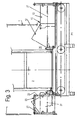
- a discharge device 5 is arranged below the ejection opening 2, which is guided and carried by a fixed to the feed mixer, rigid support frame 3 in a known manner.
- the unloading device 5 consists essentially of a push frame 6 which is divided into thrust frame halves 7, which are arranged pivotably about an axis 14 and carry at their outer ends rollers or wheels 15, which are occupied by an endless conveyor belt 16, the side edges with toothed belt and are guided over rollers, not shown, is circulated.
- the axle 14 is mounted in a middle piece 8, which is mounted on the frame of the push frame 6.
- the opposite side walls 23 are fixedly attached to the side members of the thrust frame halves 7 in a known manner, a shield 4 avoids feed losses in the central region.
- the unloading device is in the middle position M.
- the unloading device 5 For discharging feed into feed passages or into low feed troughs, the unloading device 5 remains in the middle position M.
- the unloading device 5 has a substantially mirror-inverted construction about the axis 14 and the feed application takes place in increased feed troughs on both sides under correspondingly identical conditions, only the displacement to one side is described and illustrated in the drawings.
- the unloading device 5 is moved to the unloading side, up to the position P1.
- the two-part, telescoping side wall 10 which consists of the nested plates 12 and 13 extends, the plate 12 with its bearing eyes 11 on the existing arc steel sheet 18 of a holder 17 which is fixedly mounted on the mixing container 1, on, from and is laterally pivotally connected.
- the plate 13 is provided at the outer end with bearings 19 in which it is pivotally mounted on the leg 21 of a bracket 20 from which it is supported.
- the further leg 22 of the bracket 20 is pivotable in bearings 19, arranged at the end of the push frame half 7 and on the side wall 23 fixed thereon.
- the push frame half 7 is raised from the position P1 to the position P2.
- the plates 12 and 13 are again partially moved into each other, the plate 12 is guided along the sheet 18 and the edge 24 reaches into the immediate vicinity of the discharge opening 2.
- the existing in position M or P1 gap 26 is closed.
- the edge 24 is extended so far that it covers approximately the entire height of the discharge opening 2 and prevents swelling, urging to the side mix on escape.
- the push frame 6 is displaced so far that the opposite end is located in the vicinity of the ejection opening 2.
- the side wall 10 can not be pushed together in the middle position M. Nevertheless, in order to make the shift to the positions P1 and P2, it is pivotally mounted at one end, laterally about a vertical axis on the arch 18 and at the other end about the leg 21 of the bracket 20 carrying them.
- a tension spring 27 which is secured at one end to the plate 12 and at the other end to the plate 13, supports the telescopically guided plates 12 and 13 in the displacements and avoids falling apart thereof.
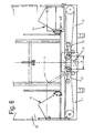
- the distance A of the axes 32 and 33 with each other corresponds to the width difference to be bridged, which can be predetermined for example by mixing containers of different widths 1 and 30, the axes 32 and 33, about which the thrust frame halves 7 each pivot when discharging feed in higher lying Fütterertröge, in all versions have a roughly equal propriety B to the outer contours of the mixing container 1 and 30.
- the guide rollers or rollers of the conveyor belt 16 are the same design in all versions. However, the respective conveyor belt 16 or 16 'is replaced by an adapted, longer.
- the conveyor belt 101 is in an embodiment of the invention of a with its side walls 104 and cross members 103 only partially shown frame 102, which is on a Futterverteil- and feed mixer below a discharge opening, through which cattle feed is placed on the conveyor belt 101.
- the feed placed on the conveyor belt 101 is guided, depending on the direction of travel of the conveyor belt, to the left or right side of the wagon and delivered to feed channels or feed troughs.
- the conveyor belt 101 essentially forms a unit of conveyor belt 113, cam belts 106 and 107 and support rods 115.
- the conveyor belt 113 is occupied on the outside with Hutprofilstegen 114 extending transversely to the direction across the full width and in their cavities they cross-carrying rods 115 record.
- the support rods 115 are flattened at both ends and provided with holes 122 for attachment by riveting or screwing with the cam belts 106 and 107.
- the cam belts 106 and 107 have at the Via the cams 109 of the underside, the conveyor belt 101 is driven by the fixedly arranged on the axle shafts 105 finger wheels 118, whose fingers 119 engage in the gaps between the cams 109.
- the support rods 115 are attached between the cams 108, on the outside of the cam belts 106 and 107.
- the cams 108 are designed so that overhung finger and deflecting wheels can engage in the cam gaps.
- Cover rails 116 and guide rails 117 which are arranged in a known manner on the side walls 104 of the frame 102, avoid feed losses at the outer edges of the conveyor belt 101st
- These tabs 121 are with their end pieces 111 on the inner sides 110 of the cam belt 106 and 107, in the direction of the conveyor belt 113, before and under or overlap the side edges, so that the sagging in the central region of the sections A 1 is avoided. Lining escaping laterally on the conveyor belt 113 is prevented by this measure.
- the tabs 121 or at least their end pieces 111, which are arranged between the cam 109, to be omitted and replaced by webs 120 which are connected continuously and circumferentially with the cam belt 106 and 107 , which leads to a continuous support of the side edges of the conveyor belt 113 and seals completely.
- the cams 109 may be configured to undercut the web 120.
- the conveyor belt 201 is in a further embodiment of the invention by a with his side walls 204 and support bars 203 only partially shown frame 202, which is on a Futterverteil- or feed mixer below a discharge opening, through which cattle feed is placed on the conveyor belt 201.
- the feed placed on the conveyor belt 201 is guided to the left or right side of the wagon and discharged into feed channels or into feed troughs.
- the conveyor belt 201 essentially forms a unit consisting of conveyor belt 211, cam belt 206 and support rods 214.
- the conveyor belt 211 is occupied on the outside with top-hat rails 212 and drive rails 213, the full-length top-hat rails 212 being provided with through holes 215 which are preferably in alternately record the support rods 214, which are flattened at both ends and provided with holes 216 for attachment, by riveting or screwing with the cam belt 206.
- the cam belts 206 have cams 207 and 208 at the top and bottom. Via the cams 208 of the bottom, the conveyor belt 201 is driven by the finger wheels 217 fixedly mounted on the axle shafts 205, the fingers 218 of which engage in the gaps between the cams 208.
- the support rods 214 are fixed with their flattened ends.
- the cams 207 are designed as needed so that also cantilevered finger or guide wheels can engage in the gaps between the cam 207.
- a cover rail 209 is attached to the side walls 204 of the frame 202 to avoid loss of feed ever.
- the bottoms and inner side surfaces of the cover rails 209 form narrow gaps between the cam belt 206 and cams 207 by which leakage of feed is prevented.
- the inner sides of the cam belts 206 are supported at the upper run by guide rails 210 arranged under the cams 8 and / or guide rollers. This prevents sagging of the conveyor belt 201 by the weight of the feed deposited thereon.
- the cams 208 can be shortened by a distance A 2, if necessary, corresponding to the outer cam.
- the guide rail 210 we then moved into the space created.
Abstract
Description
Die vorliegende Erfindung betrifft. eine quer zur Fahrtrichtung verschiebbare Entladevorrichtung eines Futtermischwagens in der Ausgestaltung nach dem Oberbegriff des Anspruchs 1, sowie ein Förderband zum Ausbringen und Verteilen von Viehfutter nach dem Oberbegriff der Schutzansprüche 10 und 14.The present invention relates. a transversely displaceable to the direction of unloading a Futtermischwagens in the embodiment according to the preamble of
Entladevorrichtungen dieser Art sind an Futtennischwagen, die vorzugsweise mit einem mit vertikalen Mischschnecken versehenen Mischwerk ausgestattet sind, bekannt. Sie besitzen einen auf halber Länge geteilten, um eine Achse schwenkbaren Schubrahmen, dessen jeweilige Hälfte nach dem Verschieben zur Abladeseite, aus waagerechter Lage, bis zur Erreichung der Abwurfhöhe schräg gestellt wird.Discharging devices of this type are known on feeding trays, which are preferably equipped with a mixer provided with vertical mixing screws, known. They have a half-length split, pivotable about an axis push frame whose respective half is tilted after moving to the discharge side, from a horizontal position until reaching the discharge height.
Bei Transportfahrten befindet sich die Entladevorrichtung mit waagerechten Schubrahmenhälften in einer Mittelstellung, ihre Bauteile ragen über die seitlichen Konturen des Futtermischwagens nicht offensichtlich hinaus.During transport, the unloading device with horizontal push frame halves is in a middle position, its components do not protrude beyond the lateral contours of the feed mixer wagon obviously.
Das Ausbringen von Futter in Futtergängen oder in niedrige Futtertröge erfolgt aus der Mittelstellung.The application of feed in feed passages or in low feed troughs takes place from the middle position.
Für die Futterabgabe in höhere Futtertröge und die dadurch erforderliche Schrägstellung einer Schubrahmenhälfte, bei gleichzeitiger Verschiebung der Entladevorrichtung zur Abladeseite hin, treten wegen mangelnder seitlicher Führung, auf der am Mischbehälter anliegenden Seitenwand, beim Hochfördern durch herunterfallendes Fördergut Futterverluste und Verunreinigungen im Futtergang auf.For the feed delivery in higher feed troughs and the required oblique position of a push frame half, with simultaneous displacement of the unloading towards the discharge side, occur due to lack of lateral guidance on the adjoining side of the mixing container, the upfeed by falling conveyed feed losses and impurities in the feed gear.
Nach der Patentanmeldung
Förderbänder der genannten Art sind zum Beispiel durch das Gebrauchsmuster
Bei diesen Förderbändern, deren Nockenriemen und Transportbänder über Tragstäbe zu einer Einheit zusammengefasst sind, zwängen sich zwischen Nockenriemen und Transportband, an den seitlichen Stoßstellen, bzw. Nähten, Futteranteile in den Zwischenraum des Transportbandes und können hier zu Wickelerscheinungen an Fingerrädern und Achsen führen, was an diesen und am Transportband, einschließlich der Nockenriemen, zu schweren Schäden führen kann.In these conveyor belts, the cam belt and conveyor belts are summarized by support rods to a unit, between cam belt and conveyor belt, at the lateral joints, or seams, forage parts in the space of the conveyor belt and can here lead to winding phenomena on finger wheels and axles, which on these and on the conveyor belt, including the cam belt, can cause serious damage.
Seitlich am unteren Trum des Transportbandes noch entweichendes Futter verschmutzt die Futtergänge.Lining still escaping from the side of the lower run of the conveyor belt contaminates the feed passages.
Förderbänder dieser Art sind zudem aus der Patentanmeldung
Die vorliegende Erfindung hat sich die Aufgabe gestellt, die vorgenannten Mängel zu beseitigen.The present invention has the object to overcome the aforementioned deficiencies.
Die Erfindung löst diese Aufgabe durch die Merkmale der Ansprüche 1, 2, 10 und 14.The invention achieves this object by the features of
Zur Vermeidung der genannten Futterverluste und Verunreinigungen ist erfindungsgemäss nach den Ansprüchen 1 und 2 vorgesehen, an beiden Seiten der Auswurföffnung des Mischbehälters je eine teleskopartige Seitenwand an der Entladevorrichtung anzuordnen, die sich beim Hochschwenken der entsprechenden Schubrahmenhälfte anpasst.To avoid said feed losses and impurities according to the invention is provided according to
Gemäß Anspruch 10 werden die Seitenränder des Transportbandes, die insbesondere in der Mitte zwischen den in größeren Abständen angeordneten Tragstreben durchhängen und sich verwerfen, mittels überstehender Laschen an den Nockenriemen eingefasst und am Durchhängen gehindert, so dass ein Durchzwängen von Futterteilen verhindert wird.According to
Die Einfassung jeweils eines Seitenrandes bzw. der Seitenränder durch Laschen kann ein- oder beidseitig erfolgen.The border of each side edge or the side edges by tabs can be done on one or both sides.
Nach Anspruch 14 ist dabei alternativ oder zusätzlich erfindungsgemäss vorgesehen, insbesondere an den Aussenrändern der Nockenriemen, der Anteil der äusseren Nocken um einen entsprechenden Abstand zu kürzen. Der entstehende Freiraum ermöglicht dann die Anbringung von die Lücken verschliessenden Abdeckschienen. An der Unterseite des Nockenriemens kann adäquat eine Führungsschiene und/oder Führungsrollen angeordnet werden, welche ein Durchhängen des Förderbandes, neben zusätzlicher Abdichtung, vermeidet.According to claim 14, it is alternatively or additionally provided according to the invention, in particular on the outer edges of the cam belt, to reduce the proportion of the outer cams by a corresponding distance. The resulting space then allows the attachment of the gaps closing cover rails. On the underside of the cam belt can be arranged adequately a guide rail and / or guide rollers, which avoids sagging of the conveyor belt, in addition to additional sealing.
An Beispielen wird die Erfindung nachstehend beschrieben und in den Zeichnungen dargestellt.
- Fig. 1
- zeigt die Seitenansicht der Anbringung der Entnahmevorrichtung am Mischbehälter eines Futtermischwagens.
- Fig. 2
- zeigt eine Ansicht der Entnahmevorrichtung in Mittelstellung nach 1 (Schnitt A-B).
- Fig.3
- zeigt eine Ansicht entsprechend 2 mit zur Seite verschobener Entnahmevorrichtung.
- Fig.4
- zeigt eine Ansicht entsprechend 3 mit schräg ansteigender Schubrahmenhälfte.
- Fig.5
- zeigt die Draufsicht zu 4.
- Fig.6
- zeigt eine Anpassung der Entladevorrichtung an unterschiedliche Mischbehälterbreiten in Mittelstellung.
- Fig.7
- zeigt eine Ausführung nach 6 in seitlicher Abladestellung.
- Fig.8
- zeigt einen Querschnitt des Förderbandes im Bereich einer Achse
- Fig.9
- zeigt eine Seitenansicht des Förderbandes
- Fig.10
- zeigt den Querschnitt eines Nockenriemens mit Einfassung des Förderbandes
- Fig.11
- zeigt eine Draufsicht zu
Fig. 10 - Fig.12
- zeigt den Querschnitt nach
Fig. 10 mit Anordnung eines Tragstabes - Fig.13
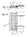
- zeigt alternativ einen weiteren Querschnitt durch einen Nockenriemen mit überstehenden Laschen und umlaufenden Steg
- Fig.14
- zeigt eine Draufsicht zu
Fig. 13 - Fig.15
- zeigt die Verbindung eines Tragstabes mit dem Transportband.
- Fig.16
- zeigt einen Querschnitt des Förderbandes.
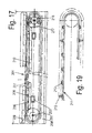
- Fig.17
- zeigt das Förderband in einer Seitenansicht.
- Fig. 18
- zeigt zur Verdeutlichung der Ansicht nach
Fig. 16 eine auseinander gezogene Ansicht der relevanten Teile. - Fig.19
- zeigt das Transportband mit Hutprofilstegen und Mitnehmerleisten in der Seitenansicht.
- Fig. 1
- shows the side view of the attachment of the sampling device to the mixing container of a feed mixer wagon.
- Fig. 2
- shows a view of the sampling device in the middle position of Figure 1 (section AB).
- Figure 3
- shows a view corresponding to FIG. 2 with side-shifted removal device.
- Figure 4
- shows a view corresponding to 3 with obliquely increasing push frame half.
- Figure 5
- shows the plan view to 4.
- Figure 6
- shows an adaptation of the unloading device to different mixing container widths in the middle position.
- Figure 7
- shows an embodiment of Figure 6 in lateral unloading position.
- Figure 8
- shows a cross section of the conveyor belt in the region of an axis
- Figure 9
- shows a side view of the conveyor belt
- Figure 10
- shows the cross section of a cam belt with enclosure of the conveyor belt
- Figure 11
- shows a plan view
Fig. 10 - Figure 12
- shows the cross section
Fig. 10 with arrangement of a support bar - Figure 13
- alternatively shows a further cross section through a cam belt with protruding tabs and circumferential ridge
- Figure 14
- shows a plan view
Fig. 13 - Figure 15
- shows the connection of a support bar with the conveyor belt.
- Figure 16
- shows a cross section of the conveyor belt.
- Figure 17
- shows the conveyor belt in a side view.
- Fig. 18
- shows for clarity the view
Fig. 16 an exploded view of the relevant parts. - Figure 19
- shows the conveyor belt with hat profile webs and carrier strips in the side view.
Am Mischbehälter 1 eines nicht näher dargestellten Futtermischwagens ist unterhalb der Auswurföffnung 2 eine Entladevorrichtung 5 angeordnet, die von einem am Futtermischwagen befestigten, starren Tragrahmen 3 in bekannter Weise geführt und getragen wird.At the mixing
Die Entladevorrichtung 5 besteht im Wesentlichen aus einem Schubrahmen 6 der in Schubrahmenhälften 7 unterteilt ist, welche um eine Achse 14 verschwenkbar angeordnet sind und an ihren äusseren Enden Walzen oder Räder 15 tragen, die von einem endlosen Förderband 16, dessen Seitenränder mit Zahnriemen besetzt sind und über nicht näher dargestellte Rollen geführt werden, umlaufen wird. Die Achse 14 ist in einem Mittelstück 8 gelagert, welches am Gestell des Schubrahmens 6 gelagert ist.The
Beidseitig neben dem Förderband 16 sind Seitenwände 10 und 23 den Schubrahmenhälften 7 zugeordnet, wobei die Seitenwände 10 an der dem Mischbehälter 1 nahe liegenden Seite teleskopartig ausgebildet sind.On both sides of the
Die gegenüberliegenden Seitenwände 23 sind in bekannter Weise fest an den Seitenträgern der Schubrahmenhälften 7 angebracht, ein Schild 4 vermeidet im mittleren Bereich Futterverluste.The
Wird kein Futter ausgetragen, z. B. bei der Befüllung oder beim Transport, befindet sich die Entladevorrichtung in Mittelstellung M.If no food is discharged, z. B. during filling or during transport, the unloading device is in the middle position M.
Zum Ausbringen von Futter in Futtergängen oder in niedrige Futtertröge, verbleibt die Entladevorrichtung 5 in der Mittelstellung M.For discharging feed into feed passages or into low feed troughs, the
Da die Entladevorrichtung 5 im Wesentlichen spiegelbildlich um die Achse 14 schwenkbar aufgebaut ist und die Futterausbringung in erhöhte Futtertröge nach beiden Seiten unter entsprechend gleichen Voraussetzungen erfolgt, wird nur die Verschiebung zu einer Seite hin beschrieben und in den Zeichnungen dargestellt.Since the
Die Entladevorrichtung 5 wird zur Abladeseite, bis in die Position P1 verschoben. Hierzu verlängert sich die zweiteilige, teleskopartige Seitenwand 10, die aus den ineinander geführten Platten 12 und 13 besteht, wobei die Platte 12 mit ihren Lageraugen 11 am aus Rundstahl bestehenden Bogen 18 eines Halters 17, der fest am Mischbehälter 1 angebracht ist, auf, ab und seitlich schwenkbar verbunden ist. Die Platte 13 ist am äusseren Ende mit Lagern 19 ausgestattet, in denen sie am Schenkel 21 eines Bügels 20, von welchem sie getragen wird, schwenkbar gelagert ist. Der weitere Schenkel 22 des Bügels 20 ist in Lagern 19 verschwenkbar, am Ende der Schubrahmenhälfte 7 und an der darauf feststehenden Seitenwand 23 angeordnet.The
Um auf die notwendige Abwurfhöhe zu gelangen, wird die Schubrahmenhälfte 7 aus der Position P1 in die Position P2 hochgestellt. Hierbei werden die Platten 12 und 13 wieder teilweise ineinander verschoben, die Platte 12 wird am Bogen 18 entlang geführt und die Kante 24 gelangt bis in die unmittelbare Nähe der Auswurföffnung 2. Die in Position M bzw. P1 vorhandene Lücke 26 ist damit geschlossen.In order to reach the necessary discharge height, the
Das Verlängern der Seitenwand 10 erfolgt über einen Anschlag 9, der an der Platte 13 befestigt ist und beim Verschieben des Schubrahmens 6 von dessen Stirnseite mitgenommen wird. Die Rückstellung erfolgt über eine Zugfeder 27.The extension of the
Durch die Spitze 25 an der Platte 12 wird die Kante 24 so weit verlängert, dass sie etwa die gesamte Höhe der Auswurföffnung 2 abdeckt und ausquellendes, zur Seite drängendes Mischgut am Entweichen hindert.By the
Befindet sich die Entladevorrichtung 1 in Position P1 oder P2, ist der Schubrahmen 6 so weit verschoben, dass sich das gegenüberliegende Ende in der Nähe der Auswurföffnung 2 befindet.If the
Die Seitenwand 10 kann in der Mittelstellung M nicht weiter zusammengeschoben werden. Um dennoch die Verschiebung in die Positionen P1 und P2 vornehmen zu können, ist sie an einem Ende, seitlich um eine vertikale Achse am Bogen 18 und am anderen Ende um den Schenkel 21 des sie tragenden Bügels 20, schwenkbar angebracht.The
Der am Schubrahmen 6 gelagerte Schenkel 22 des Bügels 20 zieht beim Verschieben in Richtung der Positionen P1 und P2 die Seitenwand 10 in Schrägstellung a und veranlasst, dass die nicht mehr verkürzbare Seitenwand 10 dieses durch Schrägstellung ausgleicht.The
Eine Zugfeder 27 die an einem Ende an der Platte 12 befestigt ist und am anderen Ende an der Platte 13, unterstützt die teleskopartig ineinander geführten Platten 12 und 13 bei den Verschiebungen und vermeidet ein Auseinanderfallen derselben.A
Das seitliche Abfallen von Futter an der dem Mischbehälter 1 nahe liegenden Seite wird bei verschiebbaren Entladevorrichtungen 5, durch die Anbringung der teleskopartigen Seitenwände 10 bei der Ausbringung in Futtergängen und höher gelegenen Futtergängen verhindert.The lateral dropping of fodder on the side close to the mixing
Das Abfallen von Futter an der untergeschobenen Stirnseite der Entladevorrichtung 5, wird durch eine an sich bekannte Abschlussplatte 29 verhindert, die mittels einer Wippe 28 an die Position P1 und die Mittelstellung angepasst ist.The falling of feed on the pushed-in end face of the
Auf die nähere Darstellung von Antriebs- und Verstellvorgängen wurde, da bekannt, verzichtet. Zur Anpassung der Entladevorrichtung an unterschiedlich breite Mischbehälter ist vorgesehen, die bereits beschriebene Ausführung für die schmalsten Baureihen der Mischbehälter 1 zu verwenden. Für breitere Mischbehälter 30 wird vorteilhaft, wegen Übernahme der relevanten Bauteile das eine Achse 14 tragende Mittelstück 8 des Schubrahmens 6 ausgetauscht und durch ein zwei Achsen 32 und 33 tragendes Mittelstück 31 ersetzt.On the closer representation of drive and Verstellvorgängen was, as known, waived. In order to adapt the unloading device to mixing containers of different widths, it is provided to use the embodiment already described for the narrowest series of mixing
Der Abstand A der Achsen 32 und 33 untereinander entspricht der zu überbrückenden Breitendifferenz, die beispielsweise durch Mischbehälter unterschiedlicher Breite 1 und 30 vorgegeben sein kann, wobei die Achsen 32 und 33, um welche die Schubrahmenhälften 7 jeweils schwenken, beim Austragen von Futter in höher liegende Futtertröge, bei allen Ausführungen einen in etwa gleichen Anstand B zu den Aussenkonturen der Mischbehälter 1 und 30 aufweisen.The distance A of the
Die Führungswalzen bzw. -rollen des Förderbandes 16 sind in allen Ausführungen gleich gestaltet. Das jeweilige Förderband 16 bzw. 16' ist jedoch durch ein angepasstes, längeres zu ersetzen.The guide rollers or rollers of the
Wird die Auswurföffnung 2 der Mischbehälter 30 um den Abstand A verbreitert, sind die Anlageverhältnisse der Kante 24 unverändert. Bei Beibehaltung der Breite der Auswurföffnung 2 sind, um die entstehende Lücke zur Kante 24 zu schliessen, Stege 34 am Behälter 30 anzubringen.If the ejection opening 2 of the mixing
Das Förderband 101 wird in einem erfindungsgemäßen Ausführungsbeispiel von eine mit seinen Seitenwänden 104 und Querholmen 103 nur teilweise dargestellten Rahmengestell 102, welches an einem Futterverteil- und Futtermischwagen unterhalb einer Ausbringöffnung, durch welche Viehfutter auf das Förderband 101 gelegt wird, getragen. Das auf das Förderband 101 gelegte Futter wird, je nach Laufrichtung des Förderbandes, zur linken oder rechten Wagenseite geführt und in Futtergänge oder Futtertröge abgegeben.The
Das Förderband 101 bildet im Wesentlichen eine Einheit aus Transportband 113, Nockenriemen 106 und 107 und Tragstäben 115. Das Transportband 113 ist an der Außenseite mit Hutprofilstegen 114 besetzt, die sich quer zur Laufrichtung über die volle Breite erstrecken und in ihren Hohlräumen die sie durchgreifenden Tragstäbe 115 aufnehmen. Die Tragstäbe 115 sind an beiden Enden abgeplattet und mit Löchern 122, zur Befestigung durch Vernietung oder Verschraubung mit den Nockenriemen 106 und 107, versehen. Die Nockenriemen 106 und 107 besitzen an der Oberseite und an der Unterseite Nocken 108 und 109. Über die Nocken 109 der Unterseite wird das Förderband 101 von den auf den Achswellen 105 fest angeordneten Fingerrädern 118, deren Finger 119 in die Lücken zwischen den Nocken 109 eingreifen, angetrieben.The
Zwischen den Nocken 108, auf der Außenseite der Nockenriemen 106 und 107, sind die Tragstäbe 115, in Abschnitte A bildender Aufteilung, befestigt. Die Nocken 108 sind so ausgeführt, dass fliegend gelagerte Finger- und Umlenkräder in die Nockenlücken eingreifen können.Between the
Abdeckschienen 116 und Führungsschienen 117, die in bekannter Weise an den Seitenwänden 104 des Rahmengestells 102 angeordnet sind, vermeiden Futterverluste an den äußeren Rändern des Förderbandes 101.Cover rails 116 and
Um weitere Futterverluste zu vermeiden, die zwischen den Nockenriemen 106 und 107 und dem Transportband 113 auftreten können, verursacht durch ein Durchhängen des Transportbandes 113 zwischen zwei Tragstäben 115, in der Mitte der Abschnitte A1, werden, um dort auftretende Spalte zu schließen, zwischen den Nocken 108 und 109 Laschen 121 angeordnet.In order to avoid further loss of feed, which may occur between the
Diese Laschen 121 stehen mit ihren Endstücken 111 an den Innenseiten 110 der Nockenriemen 106 und 107, in Richtung auf das Transportband 113, vor und unter- bzw. übergreifen dessen Seitenränder, so dass das Durchhängen im mittleren Bereich der Abschnitte A1 vermieden wird. Seitlich am Transportband 113 entweichendes Futter wird durch diese Maßnahme unterbunden.These
In einer weiteren erfindungsgemäßen Ausführung ist vorgesehen, die Laschen 121, bzw. zumindest deren Endstücke 111, die zwischen den Nocken 109 angeordnet sind, entfallen zu lassen und durch Stege 120, die durchgehend und umlaufend mit den Nockenriemen 106 und 107 verbunden sind, zu ersetzen, was zu einer durchgehenden Auflage der Seitenränder des Transportbandes 113 führt und lückenlos abdichtet.In a further embodiment of the invention is provided, the
Ferner besteht die Möglichkeit, die Laschen 121 zwischen den Nocken 108 entfallen zu lassen und deren Endstücke 111 durch einen umlaufenden Steg 112 zu ersetzen, durch die entstehende Überdeckung des Transportbandes 113 wird es von den Stegen 112 und 120 eingefasst, was die Abdichtung optimal gestaltet.It is also possible to omit the
Die Nocken 109 können so ausgebildet sein, dass sie den Steg 120 unterlaufen.The
Das Förderband 201 wird in einem weiteren erfindungsgemäßen Ausführungsbeispiel von einem mit seinen Seitenwänden 204 und Trageholmen 203 nur teilweise dargestellten Rahmengestell 202, welches an einem Futterverteil- oder Futtermischwagen unterhalb einer Ausbringöffnung, durch welche Viehfutter auf das Förderband 201 gelegt wird, getragen. Das auf das Förderband 201 gelegte Futter wird, je nach Laufrichtung des Förderbandes, zur linken oder rechten Wagenseite geführt und in Futtergänge oder in Futtertröge abgegeben.The
Das Förderband 201 bildet im Wesentlichen eine Einheit aus Transportband 211, Nockenriemen 206 und Tragstäben 214. Das Transportband 211 ist an der Aussenseite mit Hutprofilstegen 212 und Mitnehmerleisten 213 besetzt, wobei die Hutprofilstege 212 in voller Länge mit durchgehenden Löchern 215 versehen sind, die vorzugsweise in abwechselnder Reihenfolge die Tragstäbe 214 aufnehmen, welche an beiden Enden abgeplattet und mit Löchern 216 zur Befestigung, durch Vernietung oder Verschraubung mit den Nockenriemen 206 versehen sind. Die Nockenriemen 206 besitzen an der Oberseite und Unterseite Nocken 207 und 208. Über die Nocken 208 der Unterseite wird das Förderband 201 von den auf den Achswellen 205 fest angeordnete Fingerrädern 217, deren Finger 218 in die Lücken zwischen den Nocken 208 eingreifen, angetrieben.The
Zwischen den Nocken 207 auf der Aussenseite des Nockenriemens 206 sind die Tragstäbe 214 mit ihren abgeflachten Enden befestigt. Die Nocken 207 sind nach Bedarf so ausgeführt, dass auch fliegend gelagerte Finger- oder Umlenkräder in die Lücken zwischen den Nocken 207 eingreifen können.Between the
Um zu vermeiden, dass Bestandteile des Viehfutters durch die Lücken zwischen den Nocken 207 nach aussen entweichen, sind die Nocken 207 vom jeweiligen Aussenrand des Nockenriemens 206 ausgehend, um einen Abstand A1 gekürzt. In den durch die Kürzungen entstandenen Freiraum ist zur Vermeidung von Futterverlusten je eine Abdeckschiene 209 an den Seitenwänden 204 des Rahmengestells 202 angebracht. Die Unterseiten und die inneren Seitenflächen der Abdeckschienen 209 bilden enge Spalte zwischen Nockenriemen 206 und Nocken 207 durch welche ein Austreten von Futter verhindert wird.In order to avoid that components of the livestock feed escape through the gaps between the
Die Innenseiten der Nockenriemen 206 werden am oberen Trum durch unter den Nocken 8 angeordnete Führungsschienen 210 und/oder Führungsrollen unterstützt. Dieses verhindert ein Durchhängen des Förderbandes 201 durch das Gewicht des darauf abgelegten Futters. Die Nocken 208 können bei Bedarf, den äusseren Nocken entsprechend, um einen Abstand A2 gekürzt werden. Die Führungsschiene 210 wir dann in den entstandenen Freiraum nachgerückt.The inner sides of the
Werden zwischen den Achswellen 205 auf der Ober- oder Unterseite Umlenkrollen oder Unterstützungsräder angeordnet, werden die Abdeckschienen 209 oder Führungsschienen 210, durch diese bedingt, unterbrochen bzw. mehrteilig ausgeführt.Be arranged between the
- 1 :1 :
- Mischbehältermixing tank
- 2 :2:
- Auswurföffnungejection port
- 3 :3:
- Tragrahmensupporting frame
- 4 :4:
- Schildsign
- 5 :5:
- Entladevorrichtungunloader
- 6 :6:
- Schubrahmenpush frame
- 7 :7:
- SchubrahmenhälftePush frame half
- 8 :8th :
- Mittelstückcenterpiece
- 9 :9:
- Anschlagattack
- 10 :10:
- SeitenwandSide wall
- 11 :11:
- Lageraugebearing eye
- 12 :12:
- Platteplate
- 13 :13:
- Platteplate
- 14 :14:
- Achseaxis
- 15 :15:
- Walzenroll
- 16 :16:
- Förderband/16' FörderbandConveyor belt / 16 'conveyor belt
- 17 :17:
- Halterholder
- 18 :18:
- Bogenbow
- 19 :19:
- Lagercamp
- 20 :20:
- Bügelhanger
- 21 :21:
- Schenkelleg
- 22 :22:
- Schenkelleg
- 23 :23:
- SeitenwandSide wall
- 24 :24:
- Kanteedge
- 25 :25:
- Spitzetop
- 26 :26:
- Lückegap
- 27 :27:
- Zugfedermainspring
- 28 :28:
- Wippeseesaw
- 29 :29:
- AbschlussplatteEnd plate
- 30 :30:
- Mischbehälter (breit)Mixing container (wide)
- 31 :31:
- Mittelstückcenterpiece
- 32 :32:
- Achseaxis
- 33 :33:
- Achseaxis
- 34 :34:
- Stegweb
- A-B :A-B:
- Schnittcut
- M :M:
- Mittelstellungcenter position
- P1 :P1:
- Positionposition
- P2 :P2:
- Positionposition
- a :a:
- Schrägstellunginclination
- A :A:
- Abstanddistance
- B :B:
- Abstanddistance
- 101101
- Förderbandconveyor belt
- 102102
- Rahmengestellframe
- 103103
- Querholmtransverse spar
- 104104
- SeitenwandSide wall
- 105105
- Achswelleaxle shaft
- 106106
- Nockenriemencam belt
- 107107
- Nockenriemencam belt
- 108108
- Nocken (außen)Cam (outside)
- 109109
- Nocken (innen)Cam (inside)
- 110110
- Innenseiteinside
- 111111
- Endstücktail
- 112112
- Steg (oben)Footbridge (top)
- 113113
- Transportbandconveyor belt
- 114114
- HutprofilstegHutprofilsteg
- 115115
- Tragstabbearing bar
- 116116
- Abdeckschienecover rail
- 117117
- Führungsschienenguide rails
- 118118
- Fingerradfingerwheel
- 119119
- Fingerfinger
- 120120
- Steg (unten)Footbridge (below)
- 121121
- Lascheflap
- 122122
- Lochhole
- A1 A 1
- Abschnittsection
- 201 :201:
- Förderbandconveyor belt
- 202 :202:
- Rahmengestellframe
- 203 :203:
- Querholmtransverse spar
- 204 :204:
- SeitenwandSide wall
- 205 :205:
- Achswelleaxle shaft
- 206 :206:
- Nockenriemencam belt
- 207 :207:
- Nocken (aussen)Cam (outside)
- 208 :208:
- Nocken (innen)Cam (inside)
- 209 :209:
- Abdeckschienecover rail
- 210 :210:
- Führungsschieneguide rail
- 211 :211:
- Transportbandconveyor belt
- 212 :212:
- HutprofilstegHutprofilsteg
- 213 :213:
- Mitnehmerleisteentrainment
- 214 :214:
- Tragstabbearing bar
- 215 :215:
- Lochhole
- 216 :216:
- Lochhole
- 217 :217:
- Fingerradfingerwheel
- 218 :218:
- Fingerfinger
- A2 :A 2 :
- Abstanddistance
Claims (18)
Applications Claiming Priority (3)
| Application Number | Priority Date | Filing Date | Title |
|---|---|---|---|
| DE200820015432 DE202008015432U1 (en) | 2008-11-20 | 2008-11-20 | Conveyor for spreading cattle feed |
| DE200920002607 DE202009002607U1 (en) | 2009-02-24 | 2009-02-24 | Transversely displaceable to the direction of unloading a feed mixer wagon |
| DE200920008184 DE202009008184U1 (en) | 2009-06-13 | 2009-06-13 | Conveyor belt for distributing cattle feed |
Publications (3)
| Publication Number | Publication Date |
|---|---|
| EP2189058A2 true EP2189058A2 (en) | 2010-05-26 |
| EP2189058A3 EP2189058A3 (en) | 2011-11-09 |
| EP2189058B1 EP2189058B1 (en) | 2014-06-18 |
Family
ID=41785732
Family Applications (1)
| Application Number | Title | Priority Date | Filing Date |
|---|---|---|---|
| EP20090176602 Not-in-force EP2189058B1 (en) | 2008-11-20 | 2009-11-20 | Unloading device of a feed mixing car which can be moved transverse to the driving direction and a conveyor belt for taking out and distributing cattle feed |
Country Status (1)
| Country | Link |
|---|---|
| EP (1) | EP2189058B1 (en) |
Cited By (7)
| Publication number | Priority date | Publication date | Assignee | Title |
|---|---|---|---|---|
| KR101244872B1 (en) | 2012-10-21 | 2013-03-18 | 육심교 | Equipment for suppling with fodder |
| EP3058814A1 (en) * | 2015-02-17 | 2016-08-24 | B. Strautmann & Söhne GmbH u. Co. KG, | Conveyor belt for distribution of food for livestock, straw or similar materials |
| DE102015112743A1 (en) | 2015-08-03 | 2017-02-09 | B. Strautmann & Söhne GmbH u. Co. KG | Relocatable to the direction of travel unloading a feed mixer wagon with scraper floor |
| FR3061409A1 (en) * | 2017-01-05 | 2018-07-06 | Kuhn-Audureau Sa | MIXER WITH A SIDE DISCHARGE DEVICE |
| EP4005374A1 (en) * | 2020-11-30 | 2022-06-01 | Kuhn-Audureau SAS | Mixer with a two-part unloading device |
| CN114586693A (en) * | 2022-03-20 | 2022-06-07 | 李超琴 | Device capable of feeding fodder according to fodder category |
| WO2022182252A1 (en) * | 2021-02-25 | 2022-09-01 | Hustler Equipment Limited | Agricultural wagon |
Families Citing this family (1)
| Publication number | Priority date | Publication date | Assignee | Title |
|---|---|---|---|---|
| DE102018123713B4 (en) * | 2018-09-26 | 2020-12-31 | B. Strautmann & Söhne GmbH u. Co. KG | Unloading device for a mixer wagon with actively controlled locking device |
Citations (3)
| Publication number | Priority date | Publication date | Assignee | Title |
|---|---|---|---|---|
| EP1080635A1 (en) | 1999-08-28 | 2001-03-07 | Trioliet Mullos B.V. | Discharge conveyor for mobile storage wagon |
| EP1854747A1 (en) | 2006-05-10 | 2007-11-14 | Artemis Kautschuk- und Kunststoff-Technik GmbH | Cattle feeding truck |
| DE202008015432U1 (en) | 2008-11-20 | 2009-02-05 | B. Strautmann & Söhne GmbH u. Co. KG | Conveyor for spreading cattle feed |
Family Cites Families (1)
| Publication number | Priority date | Publication date | Assignee | Title |
|---|---|---|---|---|
| US4088272A (en) * | 1975-04-15 | 1978-05-09 | International Harvester Company | Bale loader and shredder |
-
2009
- 2009-11-20 EP EP20090176602 patent/EP2189058B1/en not_active Not-in-force
Patent Citations (3)
| Publication number | Priority date | Publication date | Assignee | Title |
|---|---|---|---|---|
| EP1080635A1 (en) | 1999-08-28 | 2001-03-07 | Trioliet Mullos B.V. | Discharge conveyor for mobile storage wagon |
| EP1854747A1 (en) | 2006-05-10 | 2007-11-14 | Artemis Kautschuk- und Kunststoff-Technik GmbH | Cattle feeding truck |
| DE202008015432U1 (en) | 2008-11-20 | 2009-02-05 | B. Strautmann & Söhne GmbH u. Co. KG | Conveyor for spreading cattle feed |
Cited By (10)
| Publication number | Priority date | Publication date | Assignee | Title |
|---|---|---|---|---|
| KR101244872B1 (en) | 2012-10-21 | 2013-03-18 | 육심교 | Equipment for suppling with fodder |
| EP3058814A1 (en) * | 2015-02-17 | 2016-08-24 | B. Strautmann & Söhne GmbH u. Co. KG, | Conveyor belt for distribution of food for livestock, straw or similar materials |
| DE102015112743A1 (en) | 2015-08-03 | 2017-02-09 | B. Strautmann & Söhne GmbH u. Co. KG | Relocatable to the direction of travel unloading a feed mixer wagon with scraper floor |
| FR3061409A1 (en) * | 2017-01-05 | 2018-07-06 | Kuhn-Audureau Sa | MIXER WITH A SIDE DISCHARGE DEVICE |
| EP3345475A1 (en) * | 2017-01-05 | 2018-07-11 | Kuhn-Audureau SA | Mixing wagon with lateral unloading device |
| EP4005374A1 (en) * | 2020-11-30 | 2022-06-01 | Kuhn-Audureau SAS | Mixer with a two-part unloading device |
| FR3116693A1 (en) * | 2020-11-30 | 2022-06-03 | Kuhn-Audureau S.A.S. | Mixer with a two-part unloading device |
| WO2022182252A1 (en) * | 2021-02-25 | 2022-09-01 | Hustler Equipment Limited | Agricultural wagon |
| CN114586693A (en) * | 2022-03-20 | 2022-06-07 | 李超琴 | Device capable of feeding fodder according to fodder category |
| CN114586693B (en) * | 2022-03-20 | 2023-07-14 | 张掖市迪高维尔生物科技有限公司 | Device that can carry out fodder input according to fodder category |
Also Published As
| Publication number | Publication date |
|---|---|
| EP2189058B1 (en) | 2014-06-18 |
| EP2189058A3 (en) | 2011-11-09 |
Similar Documents
| Publication | Publication Date | Title |
|---|---|---|
| EP2189058A2 (en) | Unloading device of a feed mixing car which can be moved transverse to the driving direction and a conveyor belt for taking out and distributing cattle feed | |
| DE102006022011B3 (en) | Cattle feed e.g. grass, carriage for use with tractor, has rods arranged at distance parallel to each other, planar structure covering rods for formation of conveying surface, and tappets engaged in finger wheel in form fit manner | |
| DE4115114A1 (en) | CONVEYOR DEVICE WITH MOVABLE SEPARATOR BARS | |
| DE102010045013A1 (en) | Device for conveying vehicle bodies | |
| DE1782844A1 (en) | HARVESTER | |
| EP2522545B1 (en) | Storage area of a vehicle, in particular a transport cart, storage area device and a transport cart | |
| DE1296093B (en) | Transfer device for belt conveyor | |
| DE2907818A1 (en) | MOBILE SLEEPER LAYING DEVICE | |
| DE102011118791B4 (en) | Conveyor belt for use in a milling device and milling device with such a conveyor belt | |
| EP0156207B1 (en) | Safety device around the tail pulleys of a belt conveyor | |
| EP2499336B1 (en) | Transfer station | |
| DE2906672C2 (en) | ||
| EP2058172A1 (en) | Storage space structure with movable pusher wall and transport cart with such a structure | |
| DE102018123713B4 (en) | Unloading device for a mixer wagon with actively controlled locking device | |
| CH638004A5 (en) | DRIVABLE DEVICE FOR DISTRIBUTING AND PROFILING THE BEDGING BALL OF A TRACK. | |
| DE202009002607U1 (en) | Transversely displaceable to the direction of unloading a feed mixer wagon | |
| AT511654B1 (en) | LOADING VAN FOR SCHÜTTGUT | |
| DE2610658C3 (en) | Silo system, especially for clay and clay-like masses | |
| DE19749190A1 (en) | Chain-driven sub-surface mining conveyer | |
| EP3530593B1 (en) | Vertical conveyor with drive chain and chain link, conveyor element and dispensing station | |
| DE202008015432U1 (en) | Conveyor for spreading cattle feed | |
| AT375048B (en) | RAIL-BASED TRANSPORT CARRIAGE FOR SCHUETTGUETER | |
| DD147531A5 (en) | DEVICE FOR TAKING OVER SILOGUT | |
| DE4432772A1 (en) | Housing for ship loading conveyor | |
| DE2659140C2 (en) | Baffle plate conveyor for conveying free-flowing bulk material |
Legal Events
| Date | Code | Title | Description |
|---|---|---|---|
| PUAI | Public reference made under article 153(3) epc to a published international application that has entered the european phase |
Free format text: ORIGINAL CODE: 0009012 |
|
| AK | Designated contracting states |
Kind code of ref document: A2 Designated state(s): AT BE BG CH CY CZ DE DK EE ES FI FR GB GR HR HU IE IS IT LI LT LU LV MC MK MT NL NO PL PT RO SE SI SK SM TR |
|
| AX | Request for extension of the european patent |
Extension state: AL BA RS |
|
| PUAL | Search report despatched |
Free format text: ORIGINAL CODE: 0009013 |
|
| AK | Designated contracting states |
Kind code of ref document: A3 Designated state(s): AT BE BG CH CY CZ DE DK EE ES FI FR GB GR HR HU IE IS IT LI LT LU LV MC MK MT NL NO PL PT RO SE SI SK SM TR |
|
| AX | Request for extension of the european patent |
Extension state: AL BA RS |
|
| RIC1 | Information provided on ipc code assigned before grant |
Ipc: A01K 5/00 20060101AFI20111004BHEP |
|
| 17P | Request for examination filed |
Effective date: 20120420 |
|
| GRAP | Despatch of communication of intention to grant a patent |
Free format text: ORIGINAL CODE: EPIDOSNIGR1 |
|
| INTG | Intention to grant announced |
Effective date: 20140107 |
|
| GRAS | Grant fee paid |
Free format text: ORIGINAL CODE: EPIDOSNIGR3 |
|
| GRAA | (expected) grant |
Free format text: ORIGINAL CODE: 0009210 |
|
| AK | Designated contracting states |
Kind code of ref document: B1 Designated state(s): AT BE BG CH CY CZ DE DK EE ES FI FR GB GR HR HU IE IS IT LI LT LU LV MC MK MT NL NO PL PT RO SE SI SK SM TR |
|
| REG | Reference to a national code |
Ref country code: GB Ref legal event code: FG4D Free format text: NOT ENGLISH |
|
| REG | Reference to a national code |
Ref country code: CH Ref legal event code: EP |
|
| REG | Reference to a national code |
Ref country code: AT Ref legal event code: REF Ref document number: 672790 Country of ref document: AT Kind code of ref document: T Effective date: 20140715 |
|
| REG | Reference to a national code |
Ref country code: IE Ref legal event code: FG4D Free format text: LANGUAGE OF EP DOCUMENT: GERMAN |
|
| REG | Reference to a national code |
Ref country code: DE Ref legal event code: R096 Ref document number: 502009009527 Country of ref document: DE Effective date: 20140731 |
|
| REG | Reference to a national code |
Ref country code: NL Ref legal event code: T3 |
|
| PG25 | Lapsed in a contracting state [announced via postgrant information from national office to epo] |
Ref country code: GR Free format text: LAPSE BECAUSE OF FAILURE TO SUBMIT A TRANSLATION OF THE DESCRIPTION OR TO PAY THE FEE WITHIN THE PRESCRIBED TIME-LIMIT Effective date: 20140919 Ref country code: NO Free format text: LAPSE BECAUSE OF FAILURE TO SUBMIT A TRANSLATION OF THE DESCRIPTION OR TO PAY THE FEE WITHIN THE PRESCRIBED TIME-LIMIT Effective date: 20140918 Ref country code: FI Free format text: LAPSE BECAUSE OF FAILURE TO SUBMIT A TRANSLATION OF THE DESCRIPTION OR TO PAY THE FEE WITHIN THE PRESCRIBED TIME-LIMIT Effective date: 20140618 Ref country code: LT Free format text: LAPSE BECAUSE OF FAILURE TO SUBMIT A TRANSLATION OF THE DESCRIPTION OR TO PAY THE FEE WITHIN THE PRESCRIBED TIME-LIMIT Effective date: 20140618 Ref country code: CY Free format text: LAPSE BECAUSE OF FAILURE TO SUBMIT A TRANSLATION OF THE DESCRIPTION OR TO PAY THE FEE WITHIN THE PRESCRIBED TIME-LIMIT Effective date: 20140618 |
|
| REG | Reference to a national code |
Ref country code: LT Ref legal event code: MG4D |
|
| PG25 | Lapsed in a contracting state [announced via postgrant information from national office to epo] |
Ref country code: SE Free format text: LAPSE BECAUSE OF FAILURE TO SUBMIT A TRANSLATION OF THE DESCRIPTION OR TO PAY THE FEE WITHIN THE PRESCRIBED TIME-LIMIT Effective date: 20140618 Ref country code: HR Free format text: LAPSE BECAUSE OF FAILURE TO SUBMIT A TRANSLATION OF THE DESCRIPTION OR TO PAY THE FEE WITHIN THE PRESCRIBED TIME-LIMIT Effective date: 20140618 Ref country code: LV Free format text: LAPSE BECAUSE OF FAILURE TO SUBMIT A TRANSLATION OF THE DESCRIPTION OR TO PAY THE FEE WITHIN THE PRESCRIBED TIME-LIMIT Effective date: 20140618 |
|
| PG25 | Lapsed in a contracting state [announced via postgrant information from national office to epo] |
Ref country code: PT Free format text: LAPSE BECAUSE OF FAILURE TO SUBMIT A TRANSLATION OF THE DESCRIPTION OR TO PAY THE FEE WITHIN THE PRESCRIBED TIME-LIMIT Effective date: 20141020 Ref country code: SK Free format text: LAPSE BECAUSE OF FAILURE TO SUBMIT A TRANSLATION OF THE DESCRIPTION OR TO PAY THE FEE WITHIN THE PRESCRIBED TIME-LIMIT Effective date: 20140618 Ref country code: CZ Free format text: LAPSE BECAUSE OF FAILURE TO SUBMIT A TRANSLATION OF THE DESCRIPTION OR TO PAY THE FEE WITHIN THE PRESCRIBED TIME-LIMIT Effective date: 20140618 Ref country code: ES Free format text: LAPSE BECAUSE OF FAILURE TO SUBMIT A TRANSLATION OF THE DESCRIPTION OR TO PAY THE FEE WITHIN THE PRESCRIBED TIME-LIMIT Effective date: 20140618 Ref country code: EE Free format text: LAPSE BECAUSE OF FAILURE TO SUBMIT A TRANSLATION OF THE DESCRIPTION OR TO PAY THE FEE WITHIN THE PRESCRIBED TIME-LIMIT Effective date: 20140618 Ref country code: RO Free format text: LAPSE BECAUSE OF FAILURE TO SUBMIT A TRANSLATION OF THE DESCRIPTION OR TO PAY THE FEE WITHIN THE PRESCRIBED TIME-LIMIT Effective date: 20140618 |
|
| PG25 | Lapsed in a contracting state [announced via postgrant information from national office to epo] |
Ref country code: PL Free format text: LAPSE BECAUSE OF FAILURE TO SUBMIT A TRANSLATION OF THE DESCRIPTION OR TO PAY THE FEE WITHIN THE PRESCRIBED TIME-LIMIT Effective date: 20140618 Ref country code: IS Free format text: LAPSE BECAUSE OF FAILURE TO SUBMIT A TRANSLATION OF THE DESCRIPTION OR TO PAY THE FEE WITHIN THE PRESCRIBED TIME-LIMIT Effective date: 20141018 |
|
| REG | Reference to a national code |
Ref country code: DE Ref legal event code: R097 Ref document number: 502009009527 Country of ref document: DE |
|
| PLBE | No opposition filed within time limit |
Free format text: ORIGINAL CODE: 0009261 |
|
| STAA | Information on the status of an ep patent application or granted ep patent |
Free format text: STATUS: NO OPPOSITION FILED WITHIN TIME LIMIT |
|
| PG25 | Lapsed in a contracting state [announced via postgrant information from national office to epo] |
Ref country code: DK Free format text: LAPSE BECAUSE OF FAILURE TO SUBMIT A TRANSLATION OF THE DESCRIPTION OR TO PAY THE FEE WITHIN THE PRESCRIBED TIME-LIMIT Effective date: 20140618 Ref country code: IT Free format text: LAPSE BECAUSE OF FAILURE TO SUBMIT A TRANSLATION OF THE DESCRIPTION OR TO PAY THE FEE WITHIN THE PRESCRIBED TIME-LIMIT Effective date: 20140618 |
|
| 26N | No opposition filed |
Effective date: 20150319 |
|
| PG25 | Lapsed in a contracting state [announced via postgrant information from national office to epo] |
Ref country code: BE Free format text: LAPSE BECAUSE OF NON-PAYMENT OF DUE FEES Effective date: 20141130 Ref country code: LU Free format text: LAPSE BECAUSE OF FAILURE TO SUBMIT A TRANSLATION OF THE DESCRIPTION OR TO PAY THE FEE WITHIN THE PRESCRIBED TIME-LIMIT Effective date: 20141120 Ref country code: MC Free format text: LAPSE BECAUSE OF FAILURE TO SUBMIT A TRANSLATION OF THE DESCRIPTION OR TO PAY THE FEE WITHIN THE PRESCRIBED TIME-LIMIT Effective date: 20140618 |
|
| REG | Reference to a national code |
Ref country code: CH Ref legal event code: PL |
|
| PG25 | Lapsed in a contracting state [announced via postgrant information from national office to epo] |
Ref country code: LI Free format text: LAPSE BECAUSE OF NON-PAYMENT OF DUE FEES Effective date: 20141130 Ref country code: SI Free format text: LAPSE BECAUSE OF FAILURE TO SUBMIT A TRANSLATION OF THE DESCRIPTION OR TO PAY THE FEE WITHIN THE PRESCRIBED TIME-LIMIT Effective date: 20140618 Ref country code: CH Free format text: LAPSE BECAUSE OF NON-PAYMENT OF DUE FEES Effective date: 20141130 |
|
| REG | Reference to a national code |
Ref country code: IE Ref legal event code: MM4A |
|
| PG25 | Lapsed in a contracting state [announced via postgrant information from national office to epo] |
Ref country code: IE Free format text: LAPSE BECAUSE OF NON-PAYMENT OF DUE FEES Effective date: 20141120 |
|
| REG | Reference to a national code |
Ref country code: DE Ref legal event code: R082 Ref document number: 502009009527 Country of ref document: DE Representative=s name: MEISSNER, BOLTE & PARTNER GBR, DE Ref country code: DE Ref legal event code: R082 Ref document number: 502009009527 Country of ref document: DE Representative=s name: MEISSNER BOLTE PATENTANWAELTE RECHTSANWAELTE P, DE |
|
| REG | Reference to a national code |
Ref country code: FR Ref legal event code: PLFP Year of fee payment: 7 |
|
| REG | Reference to a national code |
Ref country code: DE Ref legal event code: R082 Ref document number: 502009009527 Country of ref document: DE Representative=s name: MEISSNER, BOLTE & PARTNER GBR, DE Ref country code: DE Ref legal event code: R081 Ref document number: 502009009527 Country of ref document: DE Owner name: B. STRAUTMANN & SOEHNE GMBH U. CO. KG, DE Free format text: FORMER OWNER: B. STRAUTMANN & SOEHNE GMBH & CO. KG, 49196 BAD LAER, DE Ref country code: DE Ref legal event code: R082 Ref document number: 502009009527 Country of ref document: DE Representative=s name: MEISSNER BOLTE PATENTANWAELTE RECHTSANWAELTE P, DE |
|
| REG | Reference to a national code |
Ref country code: AT Ref legal event code: MM01 Ref document number: 672790 Country of ref document: AT Kind code of ref document: T Effective date: 20141120 |
|
| PG25 | Lapsed in a contracting state [announced via postgrant information from national office to epo] |
Ref country code: AT Free format text: LAPSE BECAUSE OF NON-PAYMENT OF DUE FEES Effective date: 20141120 |
|
| PG25 | Lapsed in a contracting state [announced via postgrant information from national office to epo] |
Ref country code: SM Free format text: LAPSE BECAUSE OF FAILURE TO SUBMIT A TRANSLATION OF THE DESCRIPTION OR TO PAY THE FEE WITHIN THE PRESCRIBED TIME-LIMIT Effective date: 20140618 |
|
| PG25 | Lapsed in a contracting state [announced via postgrant information from national office to epo] |
Ref country code: BG Free format text: LAPSE BECAUSE OF FAILURE TO SUBMIT A TRANSLATION OF THE DESCRIPTION OR TO PAY THE FEE WITHIN THE PRESCRIBED TIME-LIMIT Effective date: 20140618 |
|
| PG25 | Lapsed in a contracting state [announced via postgrant information from national office to epo] |
Ref country code: MT Free format text: LAPSE BECAUSE OF FAILURE TO SUBMIT A TRANSLATION OF THE DESCRIPTION OR TO PAY THE FEE WITHIN THE PRESCRIBED TIME-LIMIT Effective date: 20140618 Ref country code: TR Free format text: LAPSE BECAUSE OF FAILURE TO SUBMIT A TRANSLATION OF THE DESCRIPTION OR TO PAY THE FEE WITHIN THE PRESCRIBED TIME-LIMIT Effective date: 20140618 Ref country code: HU Free format text: LAPSE BECAUSE OF FAILURE TO SUBMIT A TRANSLATION OF THE DESCRIPTION OR TO PAY THE FEE WITHIN THE PRESCRIBED TIME-LIMIT; INVALID AB INITIO Effective date: 20091120 |
|
| REG | Reference to a national code |
Ref country code: FR Ref legal event code: PLFP Year of fee payment: 8 |
|
| REG | Reference to a national code |
Ref country code: FR Ref legal event code: PLFP Year of fee payment: 9 |
|
| PG25 | Lapsed in a contracting state [announced via postgrant information from national office to epo] |
Ref country code: MK Free format text: LAPSE BECAUSE OF FAILURE TO SUBMIT A TRANSLATION OF THE DESCRIPTION OR TO PAY THE FEE WITHIN THE PRESCRIBED TIME-LIMIT Effective date: 20140618 |
|
| REG | Reference to a national code |
Ref country code: FR Ref legal event code: PLFP Year of fee payment: 10 |
|
| PGFP | Annual fee paid to national office [announced via postgrant information from national office to epo] |
Ref country code: NL Payment date: 20181114 Year of fee payment: 10 |
|
| PGFP | Annual fee paid to national office [announced via postgrant information from national office to epo] |
Ref country code: DE Payment date: 20180928 Year of fee payment: 10 |
|
| PGFP | Annual fee paid to national office [announced via postgrant information from national office to epo] |
Ref country code: GB Payment date: 20181114 Year of fee payment: 10 Ref country code: FR Payment date: 20181026 Year of fee payment: 10 |
|
| REG | Reference to a national code |
Ref country code: DE Ref legal event code: R119 Ref document number: 502009009527 Country of ref document: DE |
|
| REG | Reference to a national code |
Ref country code: NL Ref legal event code: MM Effective date: 20191201 |
|
| GBPC | Gb: european patent ceased through non-payment of renewal fee |
Effective date: 20191120 |
|
| PG25 | Lapsed in a contracting state [announced via postgrant information from national office to epo] |
Ref country code: NL Free format text: LAPSE BECAUSE OF NON-PAYMENT OF DUE FEES Effective date: 20191201 |
|
| PG25 | Lapsed in a contracting state [announced via postgrant information from national office to epo] |
Ref country code: DE Free format text: LAPSE BECAUSE OF NON-PAYMENT OF DUE FEES Effective date: 20200603 Ref country code: GB Free format text: LAPSE BECAUSE OF NON-PAYMENT OF DUE FEES Effective date: 20191120 Ref country code: FR Free format text: LAPSE BECAUSE OF NON-PAYMENT OF DUE FEES Effective date: 20191130 |