EP2188176B1 - Modulare drohne mit abnehmbaren komponenten - Google Patents
Modulare drohne mit abnehmbaren komponenten Download PDFInfo
- Publication number
- EP2188176B1 EP2188176B1 EP08857634A EP08857634A EP2188176B1 EP 2188176 B1 EP2188176 B1 EP 2188176B1 EP 08857634 A EP08857634 A EP 08857634A EP 08857634 A EP08857634 A EP 08857634A EP 2188176 B1 EP2188176 B1 EP 2188176B1
- Authority
- EP
- European Patent Office
- Prior art keywords
- drone
- flying structure
- modular drone
- platen
- modular
- Prior art date
- Legal status (The legal status is an assumption and is not a legal conclusion. Google has not performed a legal analysis and makes no representation as to the accuracy of the status listed.)
- Not-in-force
Links
Images


Classifications
-
- A—HUMAN NECESSITIES
- A63—SPORTS; GAMES; AMUSEMENTS
- A63H—TOYS, e.g. TOPS, DOLLS, HOOPS OR BUILDING BLOCKS
- A63H27/00—Toy aircraft; Other flying toys
- A63H27/02—Model aircraft
-
- B—PERFORMING OPERATIONS; TRANSPORTING
- B64—AIRCRAFT; AVIATION; COSMONAUTICS
- B64U—UNMANNED AERIAL VEHICLES [UAV]; EQUIPMENT THEREFOR
- B64U10/00—Type of UAV
- B64U10/25—Fixed-wing aircraft
-
- B—PERFORMING OPERATIONS; TRANSPORTING
- B64—AIRCRAFT; AVIATION; COSMONAUTICS
- B64U—UNMANNED AERIAL VEHICLES [UAV]; EQUIPMENT THEREFOR
- B64U20/00—Constructional aspects of UAVs
- B64U20/80—Arrangement of on-board electronics, e.g. avionics systems or wiring
- B64U20/83—Electronic components structurally integrated with aircraft elements, e.g. circuit boards carrying loads
-
- B—PERFORMING OPERATIONS; TRANSPORTING
- B64—AIRCRAFT; AVIATION; COSMONAUTICS
- B64U—UNMANNED AERIAL VEHICLES [UAV]; EQUIPMENT THEREFOR
- B64U2101/00—UAVs specially adapted for particular uses or applications
- B64U2101/30—UAVs specially adapted for particular uses or applications for imaging, photography or videography
Definitions
- the present invention relates to the field of drones or "unmanned aircraft”.
- the invention can also be implemented with rotary-wing drones or other levitation means.
- a remote-controlled flying machine especially for aerial photography, comprises a pod attached detachably to a lift portion.
- the nacelle includes a low part that protrudes forward.
- the lifting part has a wing and a central beam, the wing being fixed to the central beam.
- the links between the lifting part and the lower part consist of two bolts acting as fuses in the event of a crash. These links are likely to break during a crash, thus causing the detachment of the lift portion with the lower part.
- assembly techniques use mechanical type connections, using screws, rivets, welds or clips.
- the object of the present invention is to overcome this disadvantage, by proposing a modular drone consisting of subassemblies assembled so as to separate in case of shock without causing any mechanical breakage requiring maintenance.
- the present invention also allows the absorption of a portion of the shock to reduce the overall impact on the structure of the entire apparatus, and rapid assembly and disassembly of the elements of the machine when necessary. operational.
- the present invention provides a connection between two subsets with a holding force sufficient to allow the proper operation of the device in use condition.
- the present invention proposes in its most general acceptation a modular drone consisting of a flying structure and image acquisition means, characterized in that the image acquisition means and the motorization are supported by a rigid plate connected to the flying structure by detachable links when the forces between the plate and the flying structure exceed a cut-off threshold value, these links being constituted by one of electromagnetic bonds and materials and self-gripping strips.
- the detachable links are constituted by electromagnetic bonds.
- the detachable links are preferably constituted by permanent magnets.
- the detachable links are preferably constituted by a plurality of rare earth permanent magnets arranged in a peripheral zone of the plate, the flying structure comprising permanent magnets arranged to magnetically cooperate with the permanent magnets of the plate when the two parts are assembled.
- the detachable links are constituted by electromagnets.
- the detachable links are preferably constituted by a plurality of electromagnets arranged in a peripheral zone of the plate, the flying structure comprising electromagnets arranged to magnetically cooperate with the electromagnets of the plate when the two parts are assembled.
- the detachable links are constituted by self-gripping materials.
- the detachable links are constituted by self-gripping strips.
- At least a portion of the detachable links are embedded in the flying structure or the plate.
- the plate has a cavity of a shape complementary to a protuberance for housing the onboard load.
- the plate has a plurality of electrical contacts capable of cooperating with complementary contacts provided on the flying structure, for the transmission of electrical control signals of the servomotors integral with the flying structure.
- the flying structure is provided with articulated control surfaces in connection with hinges integrated in said flying structure, as well as marginal vertical fins at its ends.
- the plate is made of carbon and the flying structure is made of expanded polypropylene.
- the modular drone is part of an airborne image acquisition system, this modular drone being able to communicate with a ground control system.
- this airborne image acquisition system comprises means for controlling the movements of the drone as a function of the target image to be acquired, this target image being determined by a user of this ground control system.
- a modular drone according to the invention is a modular wing-type drone of less than one meter wingspan and 650 grams in flight order.
- This drone is used as an airborne system for acquiring animated still images (video).
- the onboard load of this drone includes an image acquisition system capable of communicating with a system for receiving and observing images in real time on the ground.
- This image acquisition system includes an imaging system.
- the imaging system is a high definition video camera.
- the video camera may be replaced by a camera with a resolution of more than ten million pixels, a thermographic camera, or more generally by any type of imaging system.
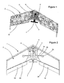
- the flying structure 2 has a total wingspan of 92 cm. It is made of expanded polypropylene. Because of its shape profiled towards the front, it plays the role of vector for the modular drone 1. At its central part, its shape is in conformity with the complement of a protuberance in order to house the onboard load 3.
- This flying structure 2 has an aerodynamic profile suitable for lift. Indeed, its geometry is arrow type, which offers a high aerodynamic lift for relatively low speeds of travel, of the order of 50 km / h.
- this flying structure 2 is provided with a device for articulated control surfaces 22 and a servo-control device, in order to control the modular drone 1 in the airspace.
- the articulated control surfaces 22 are integrated into the flying structure 2, thanks to the use hinges 24, these hinges 24 being directly integrated with the flying structure 2 by compression of the expanded polypropylene material in the manufacturing mold. This process provides increased strength for a very low mass.
- the servo-control device makes it possible to actuate the articulated control surfaces 22, via mechanical and electrical servomotors 25 integrated in the flying structure 2, these servomotors 25 being connected to the articulated control surfaces 22 with the aid of steel rods and carbon horns (not visible). Said servo motors 25 are further connected to the pilot control unit (not visible) of the drone, the steering control unit transmitting the ground control instructions by the user to the servo-motors 25.
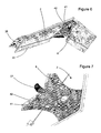
- the flying structure 2 has elongate recesses 34, as illustrated by the figure 2 . These housings allow the passage of electrical connections (not visible) between the control unit and the servo-servomotor 25, these elongate recesses 34 being associated with a carbon spar 35.
- the servo-motors being integrated into the flying structure 2 they are part of the consumable elements of the modular drone 1, and are replaced at the same time as the flying structure 2 when it suffered an irreversible shock during a fall of the modular drone 1.
- the carbon spar 35 from one servomotor to another, supports the aerodynamic loads that apply to the wing. It covers the elongate recess 34, as well as the electrical cables located inside the recess 34.
- the flying structure 2 has at each of its ends a marginal vertical fin 26, as illustrated by the figure 3 .
- the propellant propulsion system 7 is a conventional propulsion system in the aeronautical field. It is fixed to the plate 6 by mechanical type connections.
- the Figures 4 and 5 represent the rigid plate 6, which allows the assembly of the embedded load 3 to the flying structure 2. It consists of a rigid carbon plate. It is flat throughout its length, to its rear end which comprises the support 27 for the propellant propeller system 7.
- the onboard load 3 is furthermore constituted by the control sensor box 4 of the drone by reception of the control instructions by the user on the ground, as well as by the image acquisition system 5 by transmitting data from these images to the user. ground user.
- the electrical connectors (not visible), and a transmitting / receiving device (not visible) capable of communicating with a similar transmission / reception device provided on a ground control system.
- the modular drone 1 has a plurality of electrical connections (not visible) allowing the electrical connections between the various elements that are the control box, the image acquisition system 5, the servo-control device and the propulsion system. helix 7.
- the control sensor box 4 contains a set of sensors for providing information necessary for flying the drone in the airspace.
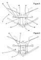
- the Figures 6 to 9 represent the connection between the flying structure 2 and the plate 6.
- the connection is made by means of eight powerful permanent magnets 41,42 of which four are embedded and glued in the flying structure and the other four are glued in the plate.
- the four magnets 41 of the plate 6 are of circular shape ( figure 4 ).
- the four magnets 42 of the flying structure 2 are of rectangular shape ( figure 8 ) and larger than the size of the magnets 41 of the plate 6, so as to ensure complete recovery of the magnets 41 of the plate 6 when the magnets 42 of the flying structure 2 are poorly centered relative to those of the plate, to a certain margin corresponding to the difference in size between the magnets of the flying structure and those of the plate ( figure 9 ). This allows a user of the drone to benefit from a certain margin of maneuver during the assembly of the flying structure 2 with the plate 6.
- the permanent magnets are Neodymium NdFeB type, surface power 12900 Gauss. This type of rare earth permanent magnet has a particularly high magnetic power to mass ratio, which offers the present embodiment a high magnetic power without significantly increasing the device. In addition, two permanent magnets thus formed are likely to disengage from one another when the forces between the plate 6 and the flying structure 2 exceed a cutoff threshold value.
- the modular drone according to the present invention also has launching means in the air, these means being necessary for the acquisition of a sufficiently high speed to benefit from the lift effect of the aerodynamic flying structure and thus ensure a take-off no motorized element in contact with the ground likely to acquire the drone sufficiently high speed, but which would significantly increase the drone.
- the flying structure 2 has two holes in the form of a half circle 51, on either side of the housing provided for the onboard load 3, as illustrated by the figure 8 .
- the plate 6 has holes in the form of a half-circle 52, on either side of the housing provided for the embedded load 3, as shown in FIG. figure 4 , of the same size as the holes 51 of the flying structure 2, and positioned so as to be superimposed with the holes 52 of the flying structure 2 when the plate 6 and the flying structure 2 are assembled ( figure 9 ). These recesses provide sufficient grip spaces for the launch to take off.
- the figure 10 represents the integration of the modular drone 1 to an airborne image acquisition system also comprising a ground control system 61 able to communicate with the modular drone 1.
- the assembly formed by this modular drone 1 and the steering system on the ground 61 allows a user to control and control the movements of the drone according to the image that it wishes to acquire.
- the image acquisition system 5 is housed in the onboard load 3. It is oriented towards the ground.
- the flying structure 2 has, at the level of the zone provided for the housing of the onboard load 3, a circular hole 62, as illustrated by the figure 4 , allowing the passage of the image acquisition system 5 to allow the latter to aim the ground when the drone has a longitudinal flight direction.
- the ground control system 61 allows a user of the drone to control it directly from the ground. It consists of a single set including a part dedicated to ground control and a part dedicated to the visualization of images in real time on the ground.
- the part dedicated to the ground control comprises a control table 63 on which can be actuated flight controls of the type "up - down - left - right” and "engine power”, as well as the control of the shooting parameters and triggering the shooting itself.
- These flight controls selected by the user on the ground, are transmitted to the flight control box (not visible) via the transmitting / receiving device 66 of the modular drone 1.
- the flying structure 2 is integral with the flight control system. acquisition of images 5 via rigid connections of the magnetic type, the flight controls orient both the flying structure 2 and the image acquisition system 5.
- the part dedicated to the visualization of the images in real time on the ground allows the user to observe in real time the image acquired by the airborne image acquisition system in order to control the system according to the image that he wants to get.
- it is constituted by an image display monitor 64 of the real-time image, the monitor being connected to an electronic and computer medium 65 containing the control programs and a transmission / reception device 66 capable of communicating with the image acquisition system 5 of the modular drone 1.
- the drone differs from the drone described above in that the eight strong permanent magnets are replaced by self-gripping materials or self-gripping strips, arranged at the same locations on the flying structure and on the plate .
- the drone differs from the drone described above in that the eight strong permanent magnets are replaced by electromagnets, or more generally by electromagnetic bonds of any type.
- the ground control system 61 comprises a communication system capable of transmitting instructions to the onboard load 3, and a graphics tablet displaying in real time the image transmitted by the imaging system of said drone. , this stylus-controllable graphics tablet by which the user of the ground control system 61 can define an area on the graphics tablet to define a new shooting frame.
- the ground control system 61 has for this purpose a computing device integrating the position of the airborne system, the shooting frame as displayed on the graphics tablet and the new shooting frame as selected by the user. The computing device determines from this input data the new position to pilot the drone so that the new shooting frame is as defined by the user.
- the computing device also incorporates a motion control algorithm to recalculate in real time, after receiving the movement instruction to the new position, the trajectory of the drone allowing it to reach the new position as instructed by the ground control system 61. Finally, the ground control system 61 is able to communicate the flight instructions to the onboard load 3 of the modular drone 1.
- a modular drone according to the present invention can be used in various fields of applications, such as professional photography or television journalism. More generally it should be used in any field of application involving an airborne image acquisition system requiring access of said image acquisition system to an area of the airspace where any other airborne system of larger scale, such as a helicopter, can not access. Finally, in a nonlimiting manner, this drone can advantageously replace any other airborne image acquisition system in that its weight and its smaller scale allow it to access at least the same areas of the airspace, while by being able to provide at least equal image quality.
Landscapes
- Engineering & Computer Science (AREA)
- Mechanical Engineering (AREA)
- Remote Sensing (AREA)
- Aviation & Aerospace Engineering (AREA)
- Microelectronics & Electronic Packaging (AREA)
- Toys (AREA)
- Telescopes (AREA)
- Tents Or Canopies (AREA)
- Massaging Devices (AREA)
- Dry Shavers And Clippers (AREA)
Claims (17)
- Modulare Drohne (1), gebildet durch eine fliegende Struktur (2) und Bilderfassungsmitteln, wobei die Bilderfassungsmittel sowie die Motorisierung durch eine steife Platte (6) getragen werden, die mit der fliegenden Struktur (2) durch Verbindungen verbunden ist, die lösbar sind, wenn die Spannungen zwischen der Platte (6) und der fliegenden Struktur (2) beim Ziehen einen Schwellenwert übersteigen, dadurch gekennzeichnet, dass die Verbindungen gebildet sind aus einem von elektromagnetischen Verbindungen (41, 42) und selbsthaftenden Materialien und Bändern.
- Modulare Drohne (1) nach Anspruch 1, dadurch gekennzeichnet, dass die lösbaren Verbindungen durch elektromagnetische Verbindungen (41, 42) gebildet werden.
- Modulare Drohne (1) nach Anspruch 2, dadurch gekennzeichnet, dass die lösbaren Verbindungen durch Permanentmagnete (41, 42) gebildet werden.
- Modulare Drohne (1) nach dem vorhergehenden Anspruch, dadurch gekennzeichnet, dass die lösbaren Verbindungen durch eine Mehrzahl von Permanentmagnete aus Seltenen Erden (41) gebildet werden, die in einer Umfangszone der Platte (6) angeordnet sind, wobei die fliegende Struktur (2) Permanentmagnete (42) auf weist, die so angeordnet sind, dass diese magnetisch mit dem Permanentmagneten (41) der Platte (6) zusammenwirken, wenn die zwei Partien zusammengebaut sind.
- Modulare Drohne (1) nach Anspruch 2, dadurch gekennzeichnet, dass die lösbaren Verbindungen durch Elektromagnete gebildet werden.
- Modulare Drohne (1) nach dem vorhergehenden Anspruch, dadurch gekennzeichnet, dass die lösbaren Verbindungen durch eine Mehrzahl von Elektromagneten gebildet werden, die in einer Umfangszone der Platte (6) angeordnet sind, wobei die fliegende Struktur (2) Elektromagnete umfasst, die so angeordnet sind, dass diese magnetisch mit dem Elektromagneten der Platte (6) zusammenwirken, wenn die zwei Partien zusammengebaut sind.
- Modulare Drohne (1) nach Anspruch 1, dadurch gekennzeichnet, dass die lösbaren Verbindungen durch selbsthaftende Materialien gebildet werden.
- Modulare Drohne (1) nach Anspruch 1, dadurch gekennzeichnet, dass die lösbaren Verbindungen durch selbsthaftende Bänder gebildet werden.
- Modulare Drohne (1) nach einem der vorhergehenden Ansprüche, dadurch gekennzeichnet, dass wenigstens der Verbindungsmittel in die fliegende Struktur (2) oder die Platte (6) eingebaut ist.
- Modulare Drohne (1) nach einem der vorhergehenden Ansprüche, dadurch gekennzeichnet, dass die fliegende Struktur (2) in ihrem unteren Bereich eine ebene Zone aufweist, die mit der Implantation der Platte (6) korrespondiert, wobei diese ebene Zone einen Raum aufweist, der eine komplementäre Form zu einer Protuberanz aufweist, die auf der Platte (6) vorgesehen ist, zur Aufnahme der geladenen Ladung (3).
- Modulare Drohne (1) nach einem der vorhergehenden Ansprüche, dadurch gekennzeichnet, dass die Platte (6) eine Mehrzahl von elektrischen Kontakten auf weist, die so ausgelegt sind, dass diese mit komplementären Kontakten zusammenwirken, die auf der fliegenden Struktur (2) vorgesehen sind, um elektrische Steuersignale von Servomotoren (25), die mit der fliegenden Struktur (2) fest verbunden sind, zu übertragen.
- Modulare Drohne (1) nach einem der vorhergehenden Ansprüche, dadurch gekennzeichnet, dass die Platte (6) durch eine Kohlenstoffplatte gebildet wird.
- Modulare Drohne (1) nach einem der vorhergehenden Ansprüche, dadurch gekennzeichnet, dass die fliegende Struktur (2) aus wenigstens einem aus expandiertem Polypropylen geformten Abschnitt gebildet wird.
- Modulare Drohne (1) nach einem der vorhergehenden Ansprüche, dadurch gekennzeichnet, dass die fliegende Struktur (2) mit angelenkten Steuerflächen (22) in Verbindung mit Scharnieren (24) versehen ist, die in die fliegende Struktur (2) integriert sind.
- Modulare Drohne (1) nach einem der vorhergehenden Ansprüche, dadurch gekennzeichnet, dass die fliegende Struktur (2) an ihren Enden mit seitlichen vertikalen Flügeln (26) versehen ist.
- Lufttransportsystem für eine Bilderfassung, gebildet aus einer modularen Drohne (1) nach einem der vorhergehenden Ansprüche, und einem Boden-Steuerungssystem (61), das so ausgebildet ist, dass dieses die Fluganweisungen an das Steuergehäuse der modularen Drohne (1) kommuniziert.
- Lufttransportsystem zur Bilderfassung nach Anspruch 16, dadurch gekennzeichnet, dass das Steuergehäuse Mittel zur Regelung von Verlagerungen der Drohne in Abhängigkeit von einem zu erfassenden Zielbild umfasst, wobei das Zielbild durch einen Benutzer des Boden-Steuerungssystems (61) bestimmt wird.
Applications Claiming Priority (2)
| Application Number | Priority Date | Filing Date | Title |
|---|---|---|---|
| FR0706401A FR2920745B1 (fr) | 2007-09-12 | 2007-09-12 | Drone modulaire a sous-ensembles detachables |
| PCT/FR2008/001273 WO2009071755A1 (fr) | 2007-09-12 | 2008-09-11 | Drone modulaire a sous-ensembles detachables |
Publications (2)
| Publication Number | Publication Date |
|---|---|
| EP2188176A1 EP2188176A1 (de) | 2010-05-26 |
| EP2188176B1 true EP2188176B1 (de) | 2011-03-23 |
Family
ID=39323760
Family Applications (1)
| Application Number | Title | Priority Date | Filing Date |
|---|---|---|---|
| EP08857634A Not-in-force EP2188176B1 (de) | 2007-09-12 | 2008-09-11 | Modulare drohne mit abnehmbaren komponenten |
Country Status (5)
| Country | Link |
|---|---|
| EP (1) | EP2188176B1 (de) |
| AT (1) | ATE502847T1 (de) |
| DE (1) | DE602008005760D1 (de) |
| FR (1) | FR2920745B1 (de) |
| WO (1) | WO2009071755A1 (de) |
Cited By (1)
| Publication number | Priority date | Publication date | Assignee | Title |
|---|---|---|---|---|
| US10315528B1 (en) | 2016-02-16 | 2019-06-11 | Owen Crawford, Jr. | Unmanned vehicle and base station |
Families Citing this family (11)
| Publication number | Priority date | Publication date | Assignee | Title |
|---|---|---|---|---|
| GB2468345B (en) * | 2009-03-05 | 2014-01-15 | Cranfield Aerospace Ltd | Unmanned air vehicle (uav) control system and method |
| JP5493103B2 (ja) * | 2009-09-01 | 2014-05-14 | 独立行政法人 宇宙航空研究開発機構 | 無人飛翔体の簡易手動飛行操縦システム |
| US8500067B2 (en) * | 2009-09-09 | 2013-08-06 | Aurora Flight Sciences Corporation | Modular miniature unmanned aircraft with vectored-thrust control |
| EP2377757B1 (de) | 2010-04-19 | 2013-05-29 | Gatewing NV | Flugzeugdrohne |
| US8967526B2 (en) * | 2010-08-12 | 2015-03-03 | Abe Karem | Multi-role aircraft with interchangeable mission modules |
| US9221532B2 (en) | 2010-08-12 | 2015-12-29 | Abe Karem | Multi-role aircraft with interchangeable mission modules |
| GB2490141B (en) * | 2011-04-19 | 2015-02-11 | Blue Bear Systems Res Ltd | Air Vehicle |
| JP2012245832A (ja) * | 2011-05-26 | 2012-12-13 | Kawada Kogyo Kk | 小型無人飛行機の翼構造 |
| US9376207B2 (en) * | 2013-08-23 | 2016-06-28 | Becklin Holdings, Inc. | Fuselage indexing system and method |
| US20150130840A1 (en) * | 2013-11-08 | 2015-05-14 | Sharper Shape Ltd. | System and method for reporting events |
| CN106053466B (zh) * | 2016-05-30 | 2019-01-04 | 武汉大学 | 一种基于无人机的土体结构演变实时在线评估装置及方法 |
Family Cites Families (9)
| Publication number | Priority date | Publication date | Assignee | Title |
|---|---|---|---|---|
| US4709881A (en) * | 1986-07-09 | 1987-12-01 | Faraz Rafikian | Safety lowering or descent parachute system for disabled helicopters and other similar types of hovering aircraft |
| US5035382A (en) * | 1989-04-17 | 1991-07-30 | Aerovironment, Inc. | Rapid assembly aircraft for ground surveillance |
| JPH0818598B2 (ja) * | 1991-09-30 | 1996-02-28 | 新明和工業株式会社 | 航空機用空中撮影カメラの昇降装置 |
| WO1999037372A1 (en) * | 1998-01-20 | 1999-07-29 | Rene Boucher | Model airplane |
| US6615165B2 (en) * | 2001-09-27 | 2003-09-02 | Ernest A. Carroll | Cable connections between an unmanned aircraft and a detachable data handling module |
| FR2832383B1 (fr) * | 2001-11-19 | 2004-04-23 | Sarl Ciel Vision | Engin volant telecommande, notamment pour prise de vues aeriennes |
| US6926235B2 (en) * | 2003-06-20 | 2005-08-09 | The Boeing Company | Runway-independent omni-role modularity enhancement (ROME) vehicle |
| US20050227582A1 (en) * | 2004-01-16 | 2005-10-13 | Kloos Wade M | Composite model construction and method |
| US7237750B2 (en) * | 2004-10-29 | 2007-07-03 | L3 Communications | Autonomous, back-packable computer-controlled breakaway unmanned aerial vehicle (UAV) |
-
2007
- 2007-09-12 FR FR0706401A patent/FR2920745B1/fr not_active Expired - Fee Related
-
2008
- 2008-09-11 AT AT08857634T patent/ATE502847T1/de not_active IP Right Cessation
- 2008-09-11 WO PCT/FR2008/001273 patent/WO2009071755A1/fr not_active Ceased
- 2008-09-11 DE DE602008005760T patent/DE602008005760D1/de active Active
- 2008-09-11 EP EP08857634A patent/EP2188176B1/de not_active Not-in-force
Cited By (1)
| Publication number | Priority date | Publication date | Assignee | Title |
|---|---|---|---|---|
| US10315528B1 (en) | 2016-02-16 | 2019-06-11 | Owen Crawford, Jr. | Unmanned vehicle and base station |
Also Published As
| Publication number | Publication date |
|---|---|
| FR2920745A1 (fr) | 2009-03-13 |
| DE602008005760D1 (de) | 2011-05-05 |
| FR2920745B1 (fr) | 2010-04-23 |
| EP2188176A1 (de) | 2010-05-26 |
| ATE502847T1 (de) | 2011-04-15 |
| WO2009071755A1 (fr) | 2009-06-11 |
Similar Documents
| Publication | Publication Date | Title |
|---|---|---|
| EP2188176B1 (de) | Modulare drohne mit abnehmbaren komponenten | |
| EP3282335A1 (de) | Integriertes kontroll-/steuermodul für flugdrohne | |
| US10196138B2 (en) | Self-tightening rotor | |
| US20170073070A1 (en) | Amphibious vertical takeoff and landing unmanned device with artificial intelligence (AI) and method and system for managing a crisis environment and controlling one or more targets | |
| EP3210658B1 (de) | Drohne, die mit hochklappbaren drohnenhalterungen ausgestattet ist | |
| WO2016034819A1 (fr) | Véhicule sans pilote embarqué | |
| KR101700754B1 (ko) | 비행체의 착륙 시스템 | |
| BE1022943B1 (fr) | Drone | |
| CA2975209A1 (fr) | Aerodyne vtol a soufflante(s) axiale(s) porteuse(s) | |
| FR2983171A1 (fr) | Dispositif anti-couple a poussee longitudinale pour un giravion | |
| FR3059647A1 (fr) | Systeme comportant un drone, un fil, et une station d'accueil, permettant des atterrissages autonomes du drone en condition degradee. | |
| EP2799331B1 (de) | System und Methode zur Steuerung eines Mittels zur Nickstabilisierung eines Fluggerätes. | |
| WO2022008437A1 (fr) | Dispositif volant a decollage vertical | |
| CA2709461A1 (fr) | Dispositif de maintien en altitude d'une charge utile dont la source d'energie de maintien en altitude est permanente et extraite du milieu | |
| FR2997924A1 (fr) | Vehicule aerien a decollage vertical et vol horizontal | |
| FR2964946A1 (fr) | Petit engin volant sans pilote | |
| US20220219815A1 (en) | Unmanned Aerial Drone Crane | |
| WO2001008969A1 (fr) | Plate-forme mobile telecommandee apte a evoluer dans un milieu tel que l'eau ou l'air | |
| EP1427632B1 (de) | Fesselballon und zugehörige steuereinrichtung | |
| FR3102147A1 (fr) | Système de récupération d’un aéronef à porter | |
| EP4114725B1 (de) | Antriebsvorrichtung und zugehöriges verfahren zur steuerung der landung einer solchen antriebsvorrichtung | |
| FR3066126A1 (fr) | Drone a voilure fixe comportant deux parties distinctes | |
| WO2017125428A1 (fr) | Equipement de pilotage par teleguidage d'un engin et procede de pilotage mis en oeuvre par ledit equipement | |
| FR3085083A1 (fr) | Aéronef | |
| Ammoo et al. | Micro air vehicle: technology review and design study |
Legal Events
| Date | Code | Title | Description |
|---|---|---|---|
| PUAI | Public reference made under article 153(3) epc to a published international application that has entered the european phase |
Free format text: ORIGINAL CODE: 0009012 |
|
| 17P | Request for examination filed |
Effective date: 20100310 |
|
| AK | Designated contracting states |
Kind code of ref document: A1 Designated state(s): AT BE BG CH CY CZ DE DK EE ES FI FR GB GR HR HU IE IS IT LI LT LU LV MC MT NL NO PL PT RO SE SI SK TR |
|
| AX | Request for extension of the european patent |
Extension state: AL BA MK RS |
|
| GRAP | Despatch of communication of intention to grant a patent |
Free format text: ORIGINAL CODE: EPIDOSNIGR1 |
|
| DAX | Request for extension of the european patent (deleted) | ||
| GRAS | Grant fee paid |
Free format text: ORIGINAL CODE: EPIDOSNIGR3 |
|
| GRAA | (expected) grant |
Free format text: ORIGINAL CODE: 0009210 |
|
| AK | Designated contracting states |
Kind code of ref document: B1 Designated state(s): AT BE BG CH CY CZ DE DK EE ES FI FR GB GR HR HU IE IS IT LI LT LU LV MC MT NL NO PL PT RO SE SI SK TR |
|
| REG | Reference to a national code |
Ref country code: GB Ref legal event code: FG4D Free format text: NOT ENGLISH |
|
| REG | Reference to a national code |
Ref country code: CH Ref legal event code: EP |
|
| REG | Reference to a national code |
Ref country code: IE Ref legal event code: FG4D |
|
| REF | Corresponds to: |
Ref document number: 602008005760 Country of ref document: DE Date of ref document: 20110505 Kind code of ref document: P |
|
| REG | Reference to a national code |
Ref country code: DE Ref legal event code: R096 Ref document number: 602008005760 Country of ref document: DE Effective date: 20110505 |
|
| REG | Reference to a national code |
Ref country code: NL Ref legal event code: VDEP Effective date: 20110323 |
|
| PG25 | Lapsed in a contracting state [announced via postgrant information from national office to epo] |
Ref country code: GR Free format text: LAPSE BECAUSE OF FAILURE TO SUBMIT A TRANSLATION OF THE DESCRIPTION OR TO PAY THE FEE WITHIN THE PRESCRIBED TIME-LIMIT Effective date: 20110624 Ref country code: SE Free format text: LAPSE BECAUSE OF FAILURE TO SUBMIT A TRANSLATION OF THE DESCRIPTION OR TO PAY THE FEE WITHIN THE PRESCRIBED TIME-LIMIT Effective date: 20110323 Ref country code: LT Free format text: LAPSE BECAUSE OF FAILURE TO SUBMIT A TRANSLATION OF THE DESCRIPTION OR TO PAY THE FEE WITHIN THE PRESCRIBED TIME-LIMIT Effective date: 20110323 Ref country code: LV Free format text: LAPSE BECAUSE OF FAILURE TO SUBMIT A TRANSLATION OF THE DESCRIPTION OR TO PAY THE FEE WITHIN THE PRESCRIBED TIME-LIMIT Effective date: 20110323 Ref country code: HR Free format text: LAPSE BECAUSE OF FAILURE TO SUBMIT A TRANSLATION OF THE DESCRIPTION OR TO PAY THE FEE WITHIN THE PRESCRIBED TIME-LIMIT Effective date: 20110323 |
|
| LTIE | Lt: invalidation of european patent or patent extension |
Effective date: 20110323 |
|
| PG25 | Lapsed in a contracting state [announced via postgrant information from national office to epo] |
Ref country code: SI Free format text: LAPSE BECAUSE OF FAILURE TO SUBMIT A TRANSLATION OF THE DESCRIPTION OR TO PAY THE FEE WITHIN THE PRESCRIBED TIME-LIMIT Effective date: 20110323 Ref country code: CY Free format text: LAPSE BECAUSE OF FAILURE TO SUBMIT A TRANSLATION OF THE DESCRIPTION OR TO PAY THE FEE WITHIN THE PRESCRIBED TIME-LIMIT Effective date: 20110323 Ref country code: FI Free format text: LAPSE BECAUSE OF FAILURE TO SUBMIT A TRANSLATION OF THE DESCRIPTION OR TO PAY THE FEE WITHIN THE PRESCRIBED TIME-LIMIT Effective date: 20110323 Ref country code: BG Free format text: LAPSE BECAUSE OF FAILURE TO SUBMIT A TRANSLATION OF THE DESCRIPTION OR TO PAY THE FEE WITHIN THE PRESCRIBED TIME-LIMIT Effective date: 20110623 Ref country code: NO Free format text: LAPSE BECAUSE OF FAILURE TO SUBMIT A TRANSLATION OF THE DESCRIPTION OR TO PAY THE FEE WITHIN THE PRESCRIBED TIME-LIMIT Effective date: 20110623 Ref country code: AT Free format text: LAPSE BECAUSE OF FAILURE TO SUBMIT A TRANSLATION OF THE DESCRIPTION OR TO PAY THE FEE WITHIN THE PRESCRIBED TIME-LIMIT Effective date: 20110323 |
|
| REG | Reference to a national code |
Ref country code: IE Ref legal event code: FD4D |
|
| PG25 | Lapsed in a contracting state [announced via postgrant information from national office to epo] |
Ref country code: EE Free format text: LAPSE BECAUSE OF FAILURE TO SUBMIT A TRANSLATION OF THE DESCRIPTION OR TO PAY THE FEE WITHIN THE PRESCRIBED TIME-LIMIT Effective date: 20110323 Ref country code: PT Free format text: LAPSE BECAUSE OF FAILURE TO SUBMIT A TRANSLATION OF THE DESCRIPTION OR TO PAY THE FEE WITHIN THE PRESCRIBED TIME-LIMIT Effective date: 20110725 |
|
| PG25 | Lapsed in a contracting state [announced via postgrant information from national office to epo] |
Ref country code: CZ Free format text: LAPSE BECAUSE OF FAILURE TO SUBMIT A TRANSLATION OF THE DESCRIPTION OR TO PAY THE FEE WITHIN THE PRESCRIBED TIME-LIMIT Effective date: 20110323 Ref country code: ES Free format text: LAPSE BECAUSE OF FAILURE TO SUBMIT A TRANSLATION OF THE DESCRIPTION OR TO PAY THE FEE WITHIN THE PRESCRIBED TIME-LIMIT Effective date: 20110704 Ref country code: SK Free format text: LAPSE BECAUSE OF FAILURE TO SUBMIT A TRANSLATION OF THE DESCRIPTION OR TO PAY THE FEE WITHIN THE PRESCRIBED TIME-LIMIT Effective date: 20110323 Ref country code: IS Free format text: LAPSE BECAUSE OF FAILURE TO SUBMIT A TRANSLATION OF THE DESCRIPTION OR TO PAY THE FEE WITHIN THE PRESCRIBED TIME-LIMIT Effective date: 20110723 Ref country code: RO Free format text: LAPSE BECAUSE OF FAILURE TO SUBMIT A TRANSLATION OF THE DESCRIPTION OR TO PAY THE FEE WITHIN THE PRESCRIBED TIME-LIMIT Effective date: 20110323 |
|
| PG25 | Lapsed in a contracting state [announced via postgrant information from national office to epo] |
Ref country code: NL Free format text: LAPSE BECAUSE OF FAILURE TO SUBMIT A TRANSLATION OF THE DESCRIPTION OR TO PAY THE FEE WITHIN THE PRESCRIBED TIME-LIMIT Effective date: 20110323 |
|
| PLBE | No opposition filed within time limit |
Free format text: ORIGINAL CODE: 0009261 |
|
| STAA | Information on the status of an ep patent application or granted ep patent |
Free format text: STATUS: NO OPPOSITION FILED WITHIN TIME LIMIT |
|
| PG25 | Lapsed in a contracting state [announced via postgrant information from national office to epo] |
Ref country code: IE Free format text: LAPSE BECAUSE OF FAILURE TO SUBMIT A TRANSLATION OF THE DESCRIPTION OR TO PAY THE FEE WITHIN THE PRESCRIBED TIME-LIMIT Effective date: 20110323 |
|
| 26N | No opposition filed |
Effective date: 20111227 |
|
| PG25 | Lapsed in a contracting state [announced via postgrant information from national office to epo] |
Ref country code: DK Free format text: LAPSE BECAUSE OF FAILURE TO SUBMIT A TRANSLATION OF THE DESCRIPTION OR TO PAY THE FEE WITHIN THE PRESCRIBED TIME-LIMIT Effective date: 20110323 Ref country code: PL Free format text: LAPSE BECAUSE OF FAILURE TO SUBMIT A TRANSLATION OF THE DESCRIPTION OR TO PAY THE FEE WITHIN THE PRESCRIBED TIME-LIMIT Effective date: 20110323 |
|
| BERE | Be: lapsed |
Owner name: ALTAIR Effective date: 20110930 |
|
| REG | Reference to a national code |
Ref country code: DE Ref legal event code: R097 Ref document number: 602008005760 Country of ref document: DE Effective date: 20111227 |
|
| PG25 | Lapsed in a contracting state [announced via postgrant information from national office to epo] |
Ref country code: MC Free format text: LAPSE BECAUSE OF NON-PAYMENT OF DUE FEES Effective date: 20110930 |
|
| PG25 | Lapsed in a contracting state [announced via postgrant information from national office to epo] |
Ref country code: IT Free format text: LAPSE BECAUSE OF FAILURE TO SUBMIT A TRANSLATION OF THE DESCRIPTION OR TO PAY THE FEE WITHIN THE PRESCRIBED TIME-LIMIT Effective date: 20110323 |
|
| PG25 | Lapsed in a contracting state [announced via postgrant information from national office to epo] |
Ref country code: BE Free format text: LAPSE BECAUSE OF NON-PAYMENT OF DUE FEES Effective date: 20110930 |
|
| PGFP | Annual fee paid to national office [announced via postgrant information from national office to epo] |
Ref country code: DE Payment date: 20121003 Year of fee payment: 5 |
|
| PG25 | Lapsed in a contracting state [announced via postgrant information from national office to epo] |
Ref country code: MT Free format text: LAPSE BECAUSE OF FAILURE TO SUBMIT A TRANSLATION OF THE DESCRIPTION OR TO PAY THE FEE WITHIN THE PRESCRIBED TIME-LIMIT Effective date: 20110323 |
|
| PGFP | Annual fee paid to national office [announced via postgrant information from national office to epo] |
Ref country code: GB Payment date: 20121003 Year of fee payment: 5 |
|
| REG | Reference to a national code |
Ref country code: CH Ref legal event code: PL |
|
| PG25 | Lapsed in a contracting state [announced via postgrant information from national office to epo] |
Ref country code: LU Free format text: LAPSE BECAUSE OF NON-PAYMENT OF DUE FEES Effective date: 20110911 |
|
| PG25 | Lapsed in a contracting state [announced via postgrant information from national office to epo] |
Ref country code: CH Free format text: LAPSE BECAUSE OF NON-PAYMENT OF DUE FEES Effective date: 20120930 Ref country code: LI Free format text: LAPSE BECAUSE OF NON-PAYMENT OF DUE FEES Effective date: 20120930 |
|
| PG25 | Lapsed in a contracting state [announced via postgrant information from national office to epo] |
Ref country code: TR Free format text: LAPSE BECAUSE OF FAILURE TO SUBMIT A TRANSLATION OF THE DESCRIPTION OR TO PAY THE FEE WITHIN THE PRESCRIBED TIME-LIMIT Effective date: 20110323 |
|
| PG25 | Lapsed in a contracting state [announced via postgrant information from national office to epo] |
Ref country code: HU Free format text: LAPSE BECAUSE OF FAILURE TO SUBMIT A TRANSLATION OF THE DESCRIPTION OR TO PAY THE FEE WITHIN THE PRESCRIBED TIME-LIMIT Effective date: 20110323 |
|
| GBPC | Gb: european patent ceased through non-payment of renewal fee |
Effective date: 20130911 |
|
| REG | Reference to a national code |
Ref country code: DE Ref legal event code: R119 Ref document number: 602008005760 Country of ref document: DE Effective date: 20140401 |
|
| PG25 | Lapsed in a contracting state [announced via postgrant information from national office to epo] |
Ref country code: GB Free format text: LAPSE BECAUSE OF NON-PAYMENT OF DUE FEES Effective date: 20130911 |
|
| PG25 | Lapsed in a contracting state [announced via postgrant information from national office to epo] |
Ref country code: DE Free format text: LAPSE BECAUSE OF NON-PAYMENT OF DUE FEES Effective date: 20140401 |
|
| REG | Reference to a national code |
Ref country code: FR Ref legal event code: PLFP Year of fee payment: 9 |
|
| REG | Reference to a national code |
Ref country code: FR Ref legal event code: PLFP Year of fee payment: 10 |
|
| REG | Reference to a national code |
Ref country code: FR Ref legal event code: PLFP Year of fee payment: 11 |
|
| PGFP | Annual fee paid to national office [announced via postgrant information from national office to epo] |
Ref country code: FR Payment date: 20180927 Year of fee payment: 11 |
|
| PG25 | Lapsed in a contracting state [announced via postgrant information from national office to epo] |
Ref country code: FR Free format text: LAPSE BECAUSE OF NON-PAYMENT OF DUE FEES Effective date: 20190930 |