EP2187770B1 - Tobacco container with insert - Google Patents
Tobacco container with insert Download PDFInfo
- Publication number
- EP2187770B1 EP2187770B1 EP09723622A EP09723622A EP2187770B1 EP 2187770 B1 EP2187770 B1 EP 2187770B1 EP 09723622 A EP09723622 A EP 09723622A EP 09723622 A EP09723622 A EP 09723622A EP 2187770 B1 EP2187770 B1 EP 2187770B1
- Authority
- EP
- European Patent Office
- Prior art keywords
- liner
- lid
- sidewall
- container body
- container
- Prior art date
- Legal status (The legal status is an assumption and is not a legal conclusion. Google has not performed a legal analysis and makes no representation as to the accuracy of the status listed.)
- Not-in-force
Links
Images



Classifications
-
- B—PERFORMING OPERATIONS; TRANSPORTING
- B65—CONVEYING; PACKING; STORING; HANDLING THIN OR FILAMENTARY MATERIAL
- B65D—CONTAINERS FOR STORAGE OR TRANSPORT OF ARTICLES OR MATERIALS, e.g. BAGS, BARRELS, BOTTLES, BOXES, CANS, CARTONS, CRATES, DRUMS, JARS, TANKS, HOPPERS, FORWARDING CONTAINERS; ACCESSORIES, CLOSURES, OR FITTINGS THEREFOR; PACKAGING ELEMENTS; PACKAGES
- B65D25/00—Details of other kinds or types of rigid or semi-rigid containers
- B65D25/02—Internal fittings
-
- A—HUMAN NECESSITIES
- A24—TOBACCO; CIGARS; CIGARETTES; SIMULATED SMOKING DEVICES; SMOKERS' REQUISITES
- A24F—SMOKERS' REQUISITES; MATCH BOXES; SIMULATED SMOKING DEVICES
- A24F23/00—Cases for tobacco, snuff, or chewing tobacco
Definitions
- This invention generally relates to containers and more particularly to containers for smokeless tobacco.
- Loose tobacco and related tobacco products are typically packaged and sold in disc-shaped containers.
- the containers comprise a metal lid seated upon either a metal, plastic or cardboard can.
- a band-type label is adhesively secured over the seam between the lid and can to securely fasten the lid and the can.
- the band type label also typically will positively impact the freshness of the product.
- the label also typically includes print, images, and information regarding the tobacco product for a potential customer.
- the lid includes a relatively flat top portion and a surrounding skirt.
- the skirt terminates in a cut edge.
- a metal edge has the potential to be relatively sharp. If the sharp edges are not properly made smooth, a purchaser of the container may potentially risk suffering a laceration in one of their fingers when prying the lid from the can using the edges.
- the interface between the can and the lid typically will have a snap fit to facilitate removal and attachment of the lid and the can.
- the interface between the lid and the can affects breathability and therefore freshness of the tobacco product contained therein.
- the interface between the lid and the can may include multiple configurations.
- WO 2008/066450 discloses a snuff box comprising a lid and a bottom part.
- NL 701 68 22 discloses a container suitable for Tobacco according to the preamble of claim 1.
- the present invention relates to a container according to claim 1.
- a tobacco container comprising a lid, a container body and a liner is disclosed.
- the liner releasably connects the lid to the container body.
- Each of the lid and container body receive and connect to the liner.
- the lid and the container body are formed of metal while the liner is formed of a self-supporting plastic.
- the liner connects the container body and lid to one another without the two components contacting each other.
- a liner for a tobacco container includes a liner body and means for connecting a container lid to the liner and means for connecting a container body to the liner.
- the liner body includes a closed end wall and an annular sidewall extending from the closed end wall.
- the means for connecting a container lid to the liner are independent of the means for connecting a container body to the liner.
- FIG. 1 is a top and front perspective view of an exemplary embodiment of a tobacco can in accordance with the teachings of the present invention
- FIG. 2 is an exploded perspective illustration of the tobacco can of FIG. 1 ;
- FIG. 3 is a top plan view of the tobacco can of FIG. 1 ;
- FIG. 4 is a cross-sectional illustration of the tobacco can of FIG. 3 taken about cut line 4-4;
- FIG. 5 is an enlarged partial illustration of the cross-sectional illustration of FIG. 4 illustrating the engagement of the cover with the liner;
- FIG. 6 is a top and front perspective view of the liner of the tobacco can of FIG. 1 ;
- FIG. 7 is an exploded cross-sectional illustration of the tobacco can of FIG. 3 about cut line 7-7;
- FIG. 8 is an enlarged partial illustration of the cross-sectional illustration of FIG. 4 illustrating the interaction of the container body with the liner;
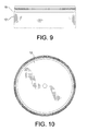
- FIG. 9 is a profile illustration of the container body coupled to the container liner, this view being identical to the front, back and other side views;
- FIG. 10 is a top view illustration of the container body coupled to the container liner of FIG. 9 ;
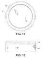
- FIG. 11 is a bottom view illustration of the container body, which is the same illustration when the container body is coupled to the container liner and/or the container lid;
- FIG. 12 is a profile illustration of the container body coupled to the container liner and container lid, this view being identical to the front, back and other side views;
- FIG. 13 is a perspective illustration of the container body coupled to the container liner of FIG. 9 .
- a container 10 is illustrated.
- the container 10 is typically employed to house chewing tobacco or other goods suitable for retail purchase by a consumer.
- the container 10 has an overall size that allows a consumer to comfortably hold the container within the palm of a hand and to store the container within a shirt pocket or in the rear pocket of a pair of blue jeans.
- the size for facilitating these tobacco container functions is between about 50 and 76 mm (2 and 3 inches) in diameter and between about (3 ⁇ 4 inches and 1 1 ⁇ 4 inches) 19 mm and 31.8 mm in axial thickness and is most typically approximately (2 1/2 inches) 63.5 mm in diameter and approximately (1 inch) 25.4 mm in axial thickness.
- the container 10 may include features that make the container more aesthetically pleasing such as, for example, color, images or prints, labels, embossing, and the like.
- the container 10 may also be secured together by, for example, a band-type adhesive label during a packaging process. After the label has been broken, the container 10 may be repeatedly opened and closed such that the consumer may access, as often as desired, a chosen amount of the contents stored in the container 10.
- the container 10 includes three components including a generally cylindrical container body 12 (a.k.a., cup or base), a lid 14 (a.k.a., cover) and an insert in the form of a liner 15.
- the container body 12, lid 14 and liner 15 are suitably formed from a variety of different materials or combinations thereof, such as metal, plastic, cardboard, and the like.
- the container body 12 and lid 14 are formed from metal while the liner 15 is formed from a plastic. More preferably, the liner 15 is formed from a sufficiently rigid plastic such as polypropylene such that the liner 15 is self-supporting.
- the lid 14 is formed from a relatively thin piece of metal (e.g., sheet metal). As shown, the lid 14 includes a circular lid top 16 and a skirt in the form of a cylindrical side wall 20 that extends from the lid top 16. The juncture of the skirt and the lid top 16 forms a shoulder 18 that may provide an upper annular recessed pocket for receiving a distal upper end 19 of the liner 15 In the illustrated embodiment, the lid 14 is a unitary body formed by lid top 16, shoulder 18, and sidewall 20. The lid top 16 and sidewall 20 generally define a cavity 22 of the lid 14 that receives an top portion of liner 15. As shown in FIG. 4 , when the lid 14 is positioned or seated upon the top portion of liner 15, an enclosed storage cavity 24 is defined within the container 10. The storage cavity 24 is where the product is stored until removed by the consumer.
- the storage cavity 24 is where the product is stored until removed by the consumer.
- the upper end 19 of the liner 15 engages the inner surface 25 of lid 14 and provides a seal therebetween to assist in maintaining the freshness of the products stored in the container 10.
- inner surfaces of the lid 14 are coated with a gold phenolic finish. Even so, in other embodiments other types of coatings or finishes may be applied to, or formed on, these interior surfaces.
- the lid top 16 generally extends radially outwardly from center point 26 between about one inch and about one and half inches. Therefore, the lid 14 has a diameter 27 of between (about two inches and about three inches) 50 and 76 mm. In the illustrated embodiment, the diameter 27 of the lid 14 is about (2.5 inches) 63.5 mm.
- the lid top 16 includes both an inner and outer surface 25, 28 (i.e., exterior and interior surface) facing in opposing directions. As the lid is formed from sheet metal, the inner and outer surfaces 25, 28 are parallel to each other.
- the lid top 16 may include embossed letters, numbers, images, and the like (collectively "characters").
- the embossed characters may project upwardly away from the container body 12 or fall downwardly into the storage cavity 24. In that regard, the embossed characters either have a height or depth of about (0.015 of an inch) 0.38 mm or less.
- Sidewall 20 extends circumferentially around lid top 16 and downward generally perpendicularly from lid top 16.
- Sidewall 20 includes both a bead 38 and a hem 40.
- the bead 38 is generally interposed between the hem 40 and shoulder 18.
- the bead 38 projects radially inward toward the center point 26 of the lid top 16. While the illustrated embodiment includes both a hem 40 and a bead 38, alternative embodiments need not include these structures.
- the bead 38 progresses circumferentially and continuously around the entire side wall 20 of the lid 14. Therefore, as the bead 38 extends around the lid 14, the bead is unbroken and uninterrupted. Even so, in another embodiment the bead 38 may be intermittently formed such that the side wall 20 is, at discrete locations, planar all the way from shoulder 18 to just above a bottom 50 of the hem 40. In such embodiments, a thin column or portion of the side wall 20 is not bowed inwardly and instead appears flat when viewed from outside the container 10.
- the hem 40 is generally a distal portion 52 of the side wall 20 folded inwardly adjacent an intermediate portion 54 of the side wall.
- the distal portion 52 is curled inwardly toward the lid top 16 to be in contact or almost contact with the inner surface of the remainder of the side wall 20.
- the distal portion 52 and the intermediate portion 54 are illustrated slightly spaced apart from each other to form channel 56 between the two portions of the side wall.
- the hem 40 because the hem 40 is a folded piece of metal, the hem generally need not be smoothed, ground, buffed, or otherwise machined to eliminate the terminating cut edge.
- the hem 40 naturally possesses a bottom 50 that is rounded and smooth.
- lid 14 More features and aspects of the lid 14 can be found in co-pending U.S. Patent Application Serial No. 11/680,333 , entitled “Lid For A Tobacco Can” filed on February 28, 2007 and assigned to the assignee of the instant application.
- the container body 12 is formed from a relatively thin piece of metal (e.g., sheet metal). As shown, the container body 12 includes a circular bottom 58 and an annular sidewall 60 that extends from and circumferentially surrounds the circular bottom 58. In the illustrated embodiment, the container body 12 is a unitary body formed by circular bottom 58 and sidewall 60. The circular bottom 58 and sidewall 60 generally define a cavity 62 of the container body 12 that receives a bottom portion of liner 15.
- the circular bottom 58 of the container body 12 includes a recessed portion 64 that is positioned radially inward from sidewall 60.
- a rolled over portion 66 forms a distal end of sidewall 60.
- the rolled over portion 66 is formed from the distal portion of sidewall 60 opposite the circular bottom 58.
- the rolled over portion 66 is rolled radially inwardly and typically has a diameter of between about (0.025 and 0.065 inch) 0.635 mm and 1.65 mm and most preferably about (0.05 inch) 1.27 mm.
- liner 15 includes a circular bottom 68 and an annular sidewall 70 that extends from and circumferentially surrounds the circular bottom 68.
- the sidewall 70 includes a top portion 72, a bottom portion 74 and an intermediate portion 76 therebetween.
- the top portion 72 is offset radially outward relative to the bottom portion 74 by tapered intermediate portion 76 such that the outer surface of bottom portion 74 is radially recessed inward relative to the radially outer surface of top portion 72.
- the top portion 72 is received by lid 14 and more particularly in cavity 22.
- the bottom portion 74 is received by container body 12 and more particularly in cavity 62.
- the top portion 72 includes a radially outward extending rib 78 (a.k.a., bead lock) that extends around sidewall 70.
- rib 78 is intermittently formed such that top portion 72 is, at discrete locations, planar all the way from shoulder 18 to intermediate portion 76 to distal upper end 19.
- the rib 78 has a plurality of segments that are angularly spaced apart forming gaps 80 therebetween. These gaps 80 assist in venting air from the lid 14 as the lid 14 is secured to the liner 15. Even so, in another embodiment, the rib 78 may be unbroken and uninterrupted.
- the bottom portion 74 includes a plurality of projections 82 extending angularly about the center point 26 of the container 10.
- the illustrated embodiment includes three such projections 82 angularly spaced about center point 26 forming gaps 85 therebetween. Even so, in another embodiment, the plurality of projections 82 may be replaced by a single continuous projection that extends around sidewall 70 unbroken and uninterrupted.
- the projections 82 include a bottom surface 84 that extends at an angle ⁇ of between 15 degrees and 45 degrees and is preferably about 30 degrees.
- the projections also include a catch surface 86 facing axially away from circular bottom 68.
- the catch surface 86 axially engages the rolled over portion 66 of container body 12 to secure the container body 12 to the liner 15.
- the catch surface 86 is generally perpendicular to sidewall 70 and is generally planar.
- the catch surface 86 typically extends between about 0.254 and 1.02 mm (0.01 and 0.04 inches) from the outer surface of the bottom portion 74 of sidewall 70, but preferably extends between about 0.508 and 0.762 mm (0.02 and 0.03 inches) from the outer surface of the bottom portion 74.
- bottom portion 74 can optionally include one or more axially extending ribs 88 that assist in spacing the container body 12 from the outer surface of sidewall 70 so as to provide a vent for expelling air as the liner 15 is inserted into cavity 62 of the container body 12.
- the inner surface of the liner 15 further includes anti-nesting projections 89 that extend radially inward from the top portion 72 and intermediate portion 76 of sidewall 70.
- the anti-nesting projections 89 extend radially inward to prevent nesting of two liners in the event that two or more liners are set on-top of one another, such as during storage or transportation.
- the liner 15 secures the lid 14 to the container body 12 without the container body 12 needing to directly contact the lid 14.
- Rolled over portion 66 and the plurality of projections 82 provide a first cooperating catch arrangement for securing the container body 12 to the bottom portion 74 of liner 15.
- the rolled over portion 66 axially engages the catch surfaces 86 of the plurality of projections 82 to prevent or oppose axial removal of the liner 15 from container body 12.
- bead 38 and rib 78 provide a second cooperating catch arrangement for securing lid 14 to the top portion 72 of liner 15.
- the bead 38 axially engages the rib 78 to prevent or oppose axial removal of the lid 14 from liner 15.
- the engagement between bead 38 and rib 78 provides for releasable securement of lid 14 to liner 15 such that the lid 14 can be repeatably secured to and removed from liner 15. This allows the consumer to open the container 10 to remove product therefrom as desired and then to close the container 10 to secure the contents therein when finished accessing the product.
- the securement between the lid 14 and liner 15 can be overcome by a lower axial loading than the securement between the container body 12 and liner 15. As such, when a consumer is holding the container 10 by the container body 12, the consumer can remove the lid 14 by axially pulling on the lid 14 without the container body 12 being removed from the liner 15.
- Top portion 72 of sidewall 70 includes several segments.
- a tapered segment 90 extends axially between upper end 19 and rib 78.
- the tapered segment 90 has an outer surface 91 that is tapered at an angle ⁇ that is between about 5 degrees and 15 degrees, but is preferably about 7 to 8 degrees, relative to inner surface 92.
- Inner surface 92 is preferably generally parallel to an axis running orthogonal between the lid top 16 and the circular bottom 68.
- the tapered configuration of tapered segment 90 assists in mounting the lid 14 to the liner 15. However, in other embodiments, the tapered segment need not be included.
- An extension segment 94 extends axially between the end of the intermediate portion 76 of sidewall 70 and the bottom of rib 78.
- the extension segment 94 in one embodiment has a constant thickness.
- the extension segment 94 and the tapered segment 90 are merely a continuous tapered portion of sidewall 70 that merely includes a rib 78 that separates the portion into different portions.
- intermediate portion 76 offsets the top portion 72 radially from the bottom portion 74.
- the intermediate portion 76 and projections 82 define relief zones 95 axially therebetween for receiving the rolled over portion 66 when the lid 14 is mounted to the liner 15.
- the container body 12 preferably engages the liner 15 such that limited to no axial slop is provided therebetween. More particularly, the liner 15 preferably cannot move axially relative to the container body 12 when the container 10 is fully assembled.
- the liner 15 includes a compression lip 96 that extends axially from an outer surface 97 of circular bottom 68.
- the compression lip 96 forms a void 93 (a.k.a., cavity) that in which the recessed portion 64 of circular bottom 58 of the container body 12 axially extends.
- the compression lip 96 of the illustrated embodiment is a plurality of segments that form an annular hub. However, the gaps between adjacent segments of the compression lip provide venting for permitting air to escape as the liner 15 and container body 12 are secured together. However, in other embodiments the compression lip could be formed from a continuous uninterrupted segment. Further yet, the compression lip need not be circular in shape and could merely be a plurality of axially extending nibs or projections that contact the bottom wall 58 of container body 12.
- the compression lip 96 extends axially from the outer surface 97 of the circular bottom 68 a distance D1 of between about (0.04 inch to about 0.1 inch) 1.02 mm to about 0.254 mm, however, other lengths could be incorporated. Further, the compression lip 96 preferably tapers as it extends away from circular bottom 68 from a wider base portion 98 to a narrower tip 99. The taper promotes more consistent flexure of the compression lip 96 and the rigidity of the compression lip 96 increases the more the compression lip is flexed.
- the compression lip 96 When the container body 12 is connected to the liner 15, the compression lip 96 is preferably biased against the inner surface of circular bottom 58 and, at least, resiliently deformed. By resiliently deforming compression lip 96, the catch surfaces 86 of projections 82 are biased into rolled over portion 66 of the container body 12. In one embodiment, the amount of biasing provided by the compression lip 96 and engagement between the rolled over portion 66 and sidewall 70 of the liner 15 is sufficient to prevent rotation of the liner 15 relative to the container body 12. It is meant by "to prevent rotation”, to mean that more than mere simple rotation by a user of the liner 15 relative to the container body 12 is required to cause relative rotation between the two components, such as for example more than (2 inch-lbs) 0.023 kg*m of torque.
- the axial distance D2 between the catch surfaces 86 of projections 82 and the distal end of the compression lip 96 is greater than the axial distance D3 between the portion of the rolled over portion 66 axially closest the circular bottom 58 and the portion of the bottom wall 58 upon which the compression lip 96 is biased.
Landscapes
- Engineering & Computer Science (AREA)
- Mechanical Engineering (AREA)
- Closures For Containers (AREA)
- Packaging Of Annular Or Rod-Shaped Articles, Wearing Apparel, Cassettes, Or The Like (AREA)
- Details Of Rigid Or Semi-Rigid Containers (AREA)
- Packages (AREA)
Description
- This invention generally relates to containers and more particularly to containers for smokeless tobacco.
- Loose tobacco and related tobacco products are typically packaged and sold in disc-shaped containers. In many cases, the containers comprise a metal lid seated upon either a metal, plastic or cardboard can. Often, a band-type label is adhesively secured over the seam between the lid and can to securely fasten the lid and the can. The band type label also typically will positively impact the freshness of the product. The label also typically includes print, images, and information regarding the tobacco product for a potential customer.
- Conventionally, the lid includes a relatively flat top portion and a surrounding skirt. The skirt terminates in a cut edge. Considering that lids are often formed from metal (plastic lids are also common), a metal edge has the potential to be relatively sharp. If the sharp edges are not properly made smooth, a purchaser of the container may potentially risk suffering a laceration in one of their fingers when prying the lid from the can using the edges. The interface between the can and the lid typically will have a snap fit to facilitate removal and attachment of the lid and the can. The interface between the lid and the can affects breathability and therefore freshness of the tobacco product contained therein. Thus, the interface between the lid and the can may include multiple configurations.
- Unfortunately, the use of plastic or cardboard for forming the components of the can make the can look cheap or flimsy. However, forming a can entirely from metal can be difficult to connect the lid to the can and to provide a good repeatable connection between the lid and the can. The present invention is directed towards improvements over the state of the art.
-
WO 2008/066450 discloses a snuff box comprising a lid and a bottom part. -
NL 701 68 22 - The present invention relates to a container according to claim 1.
- A tobacco container comprising a lid, a container body and a liner is disclosed. The liner releasably connects the lid to the container body. Each of the lid and container body receive and connect to the liner.
- The lid and the container body are formed of metal while the liner is formed of a self-supporting plastic.
- The liner connects the container body and lid to one another without the two components contacting each other.
- A liner for a tobacco container is provided that includes a liner body and means for connecting a container lid to the liner and means for connecting a container body to the liner. The liner body includes a closed end wall and an annular sidewall extending from the closed end wall. The means for connecting a container lid to the liner are independent of the means for connecting a container body to the liner.
- Other embodiments of the invention will become more apparent from the following detailed description when taken in conjunction with the accompanying drawings.
- The accompanying drawings illustrate several aspects of the present invention and, together with the description, serve to explain the invention. In the drawings:
-
FIG. 1 is a top and front perspective view of an exemplary embodiment of a tobacco can in accordance with the teachings of the present invention; -
FIG. 2 is an exploded perspective illustration of the tobacco can ofFIG. 1 ; -
FIG. 3 is a top plan view of the tobacco can ofFIG. 1 ; -
FIG. 4 is a cross-sectional illustration of the tobacco can ofFIG. 3 taken about cut line 4-4; -
FIG. 5 is an enlarged partial illustration of the cross-sectional illustration ofFIG. 4 illustrating the engagement of the cover with the liner; -
FIG. 6 is a top and front perspective view of the liner of the tobacco can ofFIG. 1 ; -
FIG. 7 is an exploded cross-sectional illustration of the tobacco can ofFIG. 3 about cut line 7-7; -
FIG. 8 is an enlarged partial illustration of the cross-sectional illustration ofFIG. 4 illustrating the interaction of the container body with the liner; -
FIG. 9 is a profile illustration of the container body coupled to the container liner, this view being identical to the front, back and other side views; -
FIG. 10 is a top view illustration of the container body coupled to the container liner ofFIG. 9 ; -
FIG. 11 is a bottom view illustration of the container body, which is the same illustration when the container body is coupled to the container liner and/or the container lid; -
FIG. 12 is a profile illustration of the container body coupled to the container liner and container lid, this view being identical to the front, back and other side views; and -
FIG. 13 is a perspective illustration of the container body coupled to the container liner ofFIG. 9 . - While the invention will be described in connection with certain preferred embodiments, there is no intent to limit it to those embodiments. On the contrary, the intent is to cover all alternatives, modifications and equivalents as included within the scope of the invention as defined by the appended claims.
- Referring to
FIG. 1 , acontainer 10 is illustrated. Thecontainer 10 is typically employed to house chewing tobacco or other goods suitable for retail purchase by a consumer. In that regard, thecontainer 10 has an overall size that allows a consumer to comfortably hold the container within the palm of a hand and to store the container within a shirt pocket or in the rear pocket of a pair of blue jeans. Typically the size for facilitating these tobacco container functions is between about 50 and 76 mm (2 and 3 inches) in diameter and between about (¾ inches and 1 ¼ inches) 19 mm and 31.8 mm in axial thickness and is most typically approximately (2 1/2 inches) 63.5 mm in diameter and approximately (1 inch) 25.4 mm in axial thickness. - The
container 10 may include features that make the container more aesthetically pleasing such as, for example, color, images or prints, labels, embossing, and the like. Thecontainer 10 may also be secured together by, for example, a band-type adhesive label during a packaging process. After the label has been broken, thecontainer 10 may be repeatedly opened and closed such that the consumer may access, as often as desired, a chosen amount of the contents stored in thecontainer 10. - As shown in
FIG. 2 , thecontainer 10 includes three components including a generally cylindrical container body 12 (a.k.a., cup or base), a lid 14 (a.k.a., cover) and an insert in the form of aliner 15. Thecontainer body 12,lid 14 andliner 15 are suitably formed from a variety of different materials or combinations thereof, such as metal, plastic, cardboard, and the like. In a preferred embodiment, thecontainer body 12 andlid 14 are formed from metal while theliner 15 is formed from a plastic. More preferably, theliner 15 is formed from a sufficiently rigid plastic such as polypropylene such that theliner 15 is self-supporting. - With reference to
FIG. 4 , in the illustrated embodiment, thelid 14 is formed from a relatively thin piece of metal (e.g., sheet metal). As shown, thelid 14 includes acircular lid top 16 and a skirt in the form of acylindrical side wall 20 that extends from thelid top 16. The juncture of the skirt and thelid top 16 forms ashoulder 18 that may provide an upper annular recessed pocket for receiving a distalupper end 19 of theliner 15 In the illustrated embodiment, thelid 14 is a unitary body formed bylid top 16,shoulder 18, andsidewall 20. Thelid top 16 andsidewall 20 generally define acavity 22 of thelid 14 that receives an top portion ofliner 15. As shown inFIG. 4 , when thelid 14 is positioned or seated upon the top portion ofliner 15, anenclosed storage cavity 24 is defined within thecontainer 10. Thestorage cavity 24 is where the product is stored until removed by the consumer. - In one embodiment, the
upper end 19 of theliner 15 engages theinner surface 25 oflid 14 and provides a seal therebetween to assist in maintaining the freshness of the products stored in thecontainer 10. In a preferred embodiment, inner surfaces of thelid 14 are coated with a gold phenolic finish. Even so, in other embodiments other types of coatings or finishes may be applied to, or formed on, these interior surfaces. - As depicted in
FIG. 3 , Thelid top 16 generally extends radially outwardly fromcenter point 26 between about one inch and about one and half inches. Therefore, thelid 14 has adiameter 27 of between (about two inches and about three inches) 50 and 76 mm. In the illustrated embodiment, thediameter 27 of thelid 14 is about (2.5 inches) 63.5 mm. - Referring back to
FIG. 4 , thelid top 16 includes both an inner andouter surface 25, 28 (i.e., exterior and interior surface) facing in opposing directions. As the lid is formed from sheet metal, the inner andouter surfaces lid top 16 may include embossed letters, numbers, images, and the like (collectively "characters"). The embossed characters may project upwardly away from thecontainer body 12 or fall downwardly into thestorage cavity 24. In that regard, the embossed characters either have a height or depth of about (0.015 of an inch) 0.38 mm or less. -
Sidewall 20 extends circumferentially aroundlid top 16 and downward generally perpendicularly fromlid top 16. - With further reference to
FIG. 5 ,Sidewall 20 includes both abead 38 and ahem 40. Thebead 38 is generally interposed between thehem 40 andshoulder 18. Thebead 38 projects radially inward toward thecenter point 26 of thelid top 16. While the illustrated embodiment includes both ahem 40 and abead 38, alternative embodiments need not include these structures. - The
bead 38 progresses circumferentially and continuously around theentire side wall 20 of thelid 14. Therefore, as thebead 38 extends around thelid 14, the bead is unbroken and uninterrupted. Even so, in another embodiment thebead 38 may be intermittently formed such that theside wall 20 is, at discrete locations, planar all the way fromshoulder 18 to just above a bottom 50 of thehem 40. In such embodiments, a thin column or portion of theside wall 20 is not bowed inwardly and instead appears flat when viewed from outside thecontainer 10. - The
hem 40 is generally adistal portion 52 of theside wall 20 folded inwardly adjacent anintermediate portion 54 of the side wall. In other words, thedistal portion 52 is curled inwardly toward thelid top 16 to be in contact or almost contact with the inner surface of the remainder of theside wall 20. In the illustrated embodiment, thedistal portion 52 and theintermediate portion 54 are illustrated slightly spaced apart from each other to formchannel 56 between the two portions of the side wall. In the illustrated embodiment, because thehem 40 is a folded piece of metal, the hem generally need not be smoothed, ground, buffed, or otherwise machined to eliminate the terminating cut edge. Thehem 40 naturally possesses a bottom 50 that is rounded and smooth. By creating a safety edge at the bottom 50 of thelid 14 through folding instead of otherwise machining as noted above, the lid may be more quickly, easily, and cost-effectively fabricated. - More features and aspects of the
lid 14 can be found in co-pendingU.S. Patent Application Serial No. 11/680,333 - Referring to
FIGS. 4 and5 , in the illustrated embodiment, thecontainer body 12 is formed from a relatively thin piece of metal (e.g., sheet metal). As shown, thecontainer body 12 includes a circular bottom 58 and anannular sidewall 60 that extends from and circumferentially surrounds thecircular bottom 58. In the illustrated embodiment, thecontainer body 12 is a unitary body formed by circular bottom 58 andsidewall 60. The circular bottom 58 andsidewall 60 generally define acavity 62 of thecontainer body 12 that receives a bottom portion ofliner 15. - The
circular bottom 58 of thecontainer body 12 includes a recessedportion 64 that is positioned radially inward fromsidewall 60. - A rolled over
portion 66 forms a distal end ofsidewall 60. The rolled overportion 66 is formed from the distal portion ofsidewall 60 opposite thecircular bottom 58. The rolled overportion 66 is rolled radially inwardly and typically has a diameter of between about (0.025 and 0.065 inch) 0.635 mm and 1.65 mm and most preferably about (0.05 inch) 1.27 mm. - Referring to
FIGS. 4-6 ,liner 15 includes a circular bottom 68 and anannular sidewall 70 that extends from and circumferentially surrounds thecircular bottom 68. Thesidewall 70 includes atop portion 72, abottom portion 74 and anintermediate portion 76 therebetween. Thetop portion 72 is offset radially outward relative to thebottom portion 74 by taperedintermediate portion 76 such that the outer surface ofbottom portion 74 is radially recessed inward relative to the radially outer surface oftop portion 72. - The
top portion 72 is received bylid 14 and more particularly incavity 22. Thebottom portion 74 is received bycontainer body 12 and more particularly incavity 62. - The
top portion 72 includes a radially outward extending rib 78 (a.k.a., bead lock) that extends aroundsidewall 70. In one embodiment,rib 78 is intermittently formed such thattop portion 72 is, at discrete locations, planar all the way fromshoulder 18 tointermediate portion 76 to distalupper end 19. Thus, therib 78 has a plurality of segments that are angularly spaced apart forminggaps 80 therebetween. Thesegaps 80 assist in venting air from thelid 14 as thelid 14 is secured to theliner 15. Even so, in another embodiment, therib 78 may be unbroken and uninterrupted. - The
bottom portion 74 includes a plurality ofprojections 82 extending angularly about thecenter point 26 of thecontainer 10. The illustrated embodiment includes threesuch projections 82 angularly spaced aboutcenter point 26 forminggaps 85 therebetween. Even so, in another embodiment, the plurality ofprojections 82 may be replaced by a single continuous projection that extends aroundsidewall 70 unbroken and uninterrupted. - The
projections 82 include abottom surface 84 that extends at an angle β of between 15 degrees and 45 degrees and is preferably about 30 degrees. The projections also include acatch surface 86 facing axially away from circular bottom 68. Thecatch surface 86 axially engages the rolled overportion 66 ofcontainer body 12 to secure thecontainer body 12 to theliner 15. Preferably, thecatch surface 86 is generally perpendicular to sidewall 70 and is generally planar. Thecatch surface 86 typically extends between about 0.254 and 1.02 mm (0.01 and 0.04 inches) from the outer surface of thebottom portion 74 ofsidewall 70, but preferably extends between about 0.508 and 0.762 mm (0.02 and 0.03 inches) from the outer surface of thebottom portion 74. - Further yet,
bottom portion 74 can optionally include one or more axially extendingribs 88 that assist in spacing thecontainer body 12 from the outer surface ofsidewall 70 so as to provide a vent for expelling air as theliner 15 is inserted intocavity 62 of thecontainer body 12. - With reference to
FIGS. 6 and13 , the inner surface of theliner 15 further includesanti-nesting projections 89 that extend radially inward from thetop portion 72 andintermediate portion 76 ofsidewall 70. Theanti-nesting projections 89 extend radially inward to prevent nesting of two liners in the event that two or more liners are set on-top of one another, such as during storage or transportation. - The
liner 15 secures thelid 14 to thecontainer body 12 without thecontainer body 12 needing to directly contact thelid 14. - Rolled over
portion 66 and the plurality ofprojections 82 provide a first cooperating catch arrangement for securing thecontainer body 12 to thebottom portion 74 ofliner 15. The rolled overportion 66 axially engages the catch surfaces 86 of the plurality ofprojections 82 to prevent or oppose axial removal of theliner 15 fromcontainer body 12. - Similarly,
bead 38 andrib 78 provide a second cooperating catch arrangement for securinglid 14 to thetop portion 72 ofliner 15. Thebead 38 axially engages therib 78 to prevent or oppose axial removal of thelid 14 fromliner 15. - Preferably, the engagement between
bead 38 andrib 78 provides for releasable securement oflid 14 toliner 15 such that thelid 14 can be repeatably secured to and removed fromliner 15. This allows the consumer to open thecontainer 10 to remove product therefrom as desired and then to close thecontainer 10 to secure the contents therein when finished accessing the product. - Additionally, the securement between the
lid 14 andliner 15 can be overcome by a lower axial loading than the securement between thecontainer body 12 andliner 15. As such, when a consumer is holding thecontainer 10 by thecontainer body 12, the consumer can remove thelid 14 by axially pulling on thelid 14 without thecontainer body 12 being removed from theliner 15. -
Top portion 72 ofsidewall 70 includes several segments. Atapered segment 90 extends axially betweenupper end 19 andrib 78. The taperedsegment 90 has anouter surface 91 that is tapered at an angle α that is between about 5 degrees and 15 degrees, but is preferably about 7 to 8 degrees, relative toinner surface 92.Inner surface 92 is preferably generally parallel to an axis running orthogonal between thelid top 16 and thecircular bottom 68. The tapered configuration of taperedsegment 90 assists in mounting thelid 14 to theliner 15. However, in other embodiments, the tapered segment need not be included. - An
extension segment 94 extends axially between the end of theintermediate portion 76 ofsidewall 70 and the bottom ofrib 78. Theextension segment 94, in one embodiment has a constant thickness. In an alternative embodiment, theextension segment 94 and the taperedsegment 90 are merely a continuous tapered portion ofsidewall 70 that merely includes arib 78 that separates the portion into different portions. - The inclusion of
intermediate portion 76 offsets thetop portion 72 radially from thebottom portion 74. Theintermediate portion 76 andprojections 82 definerelief zones 95 axially therebetween for receiving the rolled overportion 66 when thelid 14 is mounted to theliner 15. - The
container body 12 preferably engages theliner 15 such that limited to no axial slop is provided therebetween. More particularly, theliner 15 preferably cannot move axially relative to thecontainer body 12 when thecontainer 10 is fully assembled. - With reference to
FIGS. 7 and 8 , in one embodiment, theliner 15 includes acompression lip 96 that extends axially from anouter surface 97 of circular bottom 68. Thecompression lip 96 forms a void 93 (a.k.a., cavity) that in which the recessedportion 64 ofcircular bottom 58 of thecontainer body 12 axially extends. - The
compression lip 96 of the illustrated embodiment is a plurality of segments that form an annular hub. However, the gaps between adjacent segments of the compression lip provide venting for permitting air to escape as theliner 15 andcontainer body 12 are secured together. However, in other embodiments the compression lip could be formed from a continuous uninterrupted segment. Further yet, the compression lip need not be circular in shape and could merely be a plurality of axially extending nibs or projections that contact thebottom wall 58 ofcontainer body 12. - As illustrated, the
compression lip 96 extends axially from theouter surface 97 of the circular bottom 68 a distance D1 of between about (0.04 inch to about 0.1 inch) 1.02 mm to about 0.254 mm, however, other lengths could be incorporated. Further, thecompression lip 96 preferably tapers as it extends away from circular bottom 68 from awider base portion 98 to anarrower tip 99. The taper promotes more consistent flexure of thecompression lip 96 and the rigidity of thecompression lip 96 increases the more the compression lip is flexed. - When the
container body 12 is connected to theliner 15, thecompression lip 96 is preferably biased against the inner surface of circular bottom 58 and, at least, resiliently deformed. By resiliently deformingcompression lip 96, the catch surfaces 86 ofprojections 82 are biased into rolled overportion 66 of thecontainer body 12. In one embodiment, the amount of biasing provided by thecompression lip 96 and engagement between the rolled overportion 66 andsidewall 70 of theliner 15 is sufficient to prevent rotation of theliner 15 relative to thecontainer body 12. It is meant by "to prevent rotation", to mean that more than mere simple rotation by a user of theliner 15 relative to thecontainer body 12 is required to cause relative rotation between the two components, such as for example more than (2 inch-lbs) 0.023 kg*m of torque. - With reference to
FIG. 7 , in an unassembled state, the axial distance D2 between the catch surfaces 86 ofprojections 82 and the distal end of thecompression lip 96 is greater than the axial distance D3 between the portion of the rolled overportion 66 axially closest the circular bottom 58 and the portion of thebottom wall 58 upon which thecompression lip 96 is biased. - The use of the terms "a" and "an" and "the" and similar referents in the context of describing the invention is to be construed to cover both the singular and the plural, unless otherwise indicated herein or clearly contradicted by context. Recitation of ranges of values herein are merely intended to serve as a shorthand method of referring individually to each separate value falling within the range, unless otherwise indicated herein, and each separate value is incorporated into the specification as if it were individually recited herein. All methods described herein can be performed in any suitable order unless otherwise indicated herein or otherwise clearly contradicted by context. The use of any and all examples, or exemplary language (e.g., "such as") provided herein, is intended merely to better illuminate the invention and does not pose a limitation on the scope of the invention as claimed.
- Preferred embodiments of this invention are described herein, including the best mode known to the inventors for carrying out the invention. Variations of those preferred embodiments may become apparent to those of ordinary skill in the art upon reading the foregoing description. The inventors expect skilled artisans to employ such variations as appropriate, and the inventors intend for the invention to be practiced otherwise than as specifically described herein. Accordingly, this invention includes all modifications of the subject matter as recited in the claims. Moreover, any combination of the above-described elements in all possible variations thereof is encompassed by the invention unless otherwise indicated herein or otherwise clearly contradicted by context.
Claims (12)
- A tobacco container (10) comprising:a lid (14), a container body (12), and a liner (15), whereinsaid liner (15) is cup-shaped and has a body comprising a first bottom wall (68) and an annular first sidewall (70) extending from a first side of the first bottom wall (68) forming a first cavity, said liner (15) comprising means for connecting said lid (14) to said liner (15), means for connecting said container body (12) to said liner (15), both means being independent, said liner (15) being releasably connecting said lid (14) to said container body (12), each of said lid (14) and container body (12) receiving said liner (15) and connecting to said liner (15),said container body (12) is cup-shaped and comprises a second bottom (58) and an annular second sidewall (60) extending from the second bottom wall (58) forming a second cavity (62), the second cavity receiving the first bottom wall (68) and a bottom portion (74) of the first sidewall (70) of the liner (15), said lid (14) is cup-shaped and comprises a top wall (16) and an annular third sidewall (20) extending from the top wall (16) forming a third cavity (22), the third cavity (22) receiving a top portion (72) of the first sidewall (70) of the liner (15),characterized in thatsaid first sidewall (70) of said liner (15) and said second sidewall (60) of said container body (12) have a second cooperating catch arrangement for connecting said container body (12) to said liner (15) and in that said first sidewall (70) of said liner (15) and said third sidewall (20) of said lid (14) have a first cooperating catch arrangement for releasably connecting said lid (14) to said liner (15).
- The tobacco container according to claim 1, wherein the first catch arrangement for connecting said lid (14) to said liner (15) is at least one first rib (78) extending outward from an upper portion (72) of the first sidewall (70) and wherein the second catch arrangement connecting said container body (12) to said liner (15) is at least one second rib (82) extending outward from a bottom portion (74) of the first sidewall (70), said at least one second rib (82) axially spaced apart from and axially interposed between the closed end wall (58,68) and said at least one first rib (78).
- The tobacco container (10) according to claim 1 or 2, wherein the liner (15) is a self supporting structure such that it will hold its shape independent of the lid (14) and container body (12).
- The tobacco container according to claim any of the preceding claims, further including a compression lip (96) extending from a second opposite side of the first bottom wall (68), the compression lip (96) axially biased against the second bottom wall (58) and deformed when the liner (15) is connected to the container body (12).
- The tobacco container according to claim any of the preceding claims,
wherein the compression lip (96) is generally circular and is formed by a plurality of angularly spaced lip segments. - The tobacco container according to claim any of the preceding claims,
wherein the second bottom wall (58) includes a recessed region (64) radially inward from the second sidewall (60) and the compression lip (96) is generally circular defining a void (93), the recess region (64) axially extending into the void (93). - The tobacco container according to claim any of the preceding claims,
wherein a radially outer surface of the top portion (72) extends radially outward beyond a radially outer surface of the bottom portion (74). - The tobacco container according to claim any of the preceding claims,
wherein the lid (14) is axially spaced from the container body (12) forming a gap thereinbetween when the lid (14) is secured to the liner (15), such that the lid (14) does not contact the container body (12) when the lid (14) is connected to the liner (15) and the container is in a quiescent state. - The tobacco container according to claim any of the preceding claims,
wherein a distal end (19) of the first sidewall (70) contacts an inner surface (25) of the top wall (16) when the lid (14) is secured to the liner (15), and
further including at least one rib (88) extending radially outward from an outer surface of the bottom portion (74) of the first sidewall (70), the rib (88) separating at least part of the first sidewall (70) from a corresponding part of the second sidewall (60). - The tobacco container according to claim any of the preceding claims,
wherein the liner (15) is formed of a plastic material and the lid (14) and container body (12) are formed of metal. - The tobacco container according to claim any of the preceding claims, wherein:the second cooperating catch arrangement includes at least one radially outward extending second rib (82) formed on an outer surface of the bottom portion (74) of the first sidewall (70) and a radially inward folded over end portion (66) of the second sidewall (60), andthe first cooperating catch arrangement includes a radially inward extending bead (38) formed in the third sidewall (20) and a radially outward extending projection (78) of an outer surface of the top portion (72) of the first sidewall (70).
- The tobacco container according to claim 11, wherein the at least one radially outward extending projection includes a plurality of radially outward extending projections angularly spaced apart forming angular gaps thereinbetween,
wherein the connection between the liner (15) and the container body (12) is axially greater than the connection between the liner (15) and the lid (14) such that axial removal of the lid (14) from the liner (15) while grasping the container body (12) does not disconnect the container body (12) from the liner (15), and
wherein the first cooperating catch arrangement provides a snap-fit engagement between the lid (14) and the liner (15).
Applications Claiming Priority (2)
| Application Number | Priority Date | Filing Date | Title |
|---|---|---|---|
| US12/168,244 US8215482B2 (en) | 2008-07-07 | 2008-07-07 | Tobacco container with insert |
| PCT/US2009/044153 WO2010005628A2 (en) | 2008-07-07 | 2009-05-15 | Tobacco container with insert |
Publications (3)
| Publication Number | Publication Date |
|---|---|
| EP2187770A2 EP2187770A2 (en) | 2010-05-26 |
| EP2187770A4 EP2187770A4 (en) | 2010-09-15 |
| EP2187770B1 true EP2187770B1 (en) | 2012-10-31 |
Family
ID=41463517
Family Applications (1)
| Application Number | Title | Priority Date | Filing Date |
|---|---|---|---|
| EP09723622A Not-in-force EP2187770B1 (en) | 2008-07-07 | 2009-05-15 | Tobacco container with insert |
Country Status (8)
| Country | Link |
|---|---|
| US (1) | US8215482B2 (en) |
| EP (1) | EP2187770B1 (en) |
| JP (1) | JP2011527271A (en) |
| CN (1) | CN101801227B (en) |
| CA (1) | CA2684761C (en) |
| DK (1) | DK2187770T3 (en) |
| MX (1) | MX2009009611A (en) |
| WO (1) | WO2010005628A2 (en) |
Families Citing this family (38)
| Publication number | Priority date | Publication date | Assignee | Title |
|---|---|---|---|---|
| US8393465B2 (en) * | 2007-05-07 | 2013-03-12 | Philip Morris Usa Inc. | Pocket-size hybrid container for consumer items |
| DE102008027814A1 (en) * | 2008-06-11 | 2009-12-17 | Khs Ag | Container, in particular bottle with a recognition element for aligning |
| US20100012534A1 (en) * | 2008-07-18 | 2010-01-21 | J.L. Clark, Inc. | Lid for tobacco container |
| CN102131712B (en) * | 2008-08-26 | 2013-01-02 | 米德韦斯瓦科公司 | container for small items |
| GB0822657D0 (en) * | 2008-12-12 | 2009-01-21 | British American Tobacco Co | Container |
| EP2557947A1 (en) | 2010-04-14 | 2013-02-20 | Altria Client Services Inc. | Preformed smokeless tobacco product |
| CN102464152A (en) * | 2010-11-10 | 2012-05-23 | 北京万疆科技有限公司 | Aluminum-alloy sanitary cigarette box |
| USD674134S1 (en) | 2010-12-10 | 2013-01-08 | U.S. Smokeless Tobacco Company Llc | Oral tobacco article |
| USD674538S1 (en) | 2010-12-10 | 2013-01-15 | U.S. Smokeless Tobacco Company Llc | Set of oral tobacco articles |
| WO2012078960A1 (en) * | 2010-12-10 | 2012-06-14 | Altria Client Services Inc. | Smokeless tobacco packaging system and method |
| USD674537S1 (en) | 2010-12-10 | 2013-01-15 | U.S. Smokelss Tobacco Company LLC | Set of oral tobacco articles |
| USD674536S1 (en) | 2010-12-10 | 2013-01-15 | U.S. Smokeless Tobacco Company Llc | Set of oral tobacco articles |
| US20130008809A1 (en) * | 2011-07-06 | 2013-01-10 | Charles Cortez | Seal can |
| SE539642C2 (en) * | 2012-10-22 | 2017-10-24 | Modulpac Ab | Packaging with guarantee seal and method of packing and sealing the package |
| US10604302B2 (en) * | 2012-11-20 | 2020-03-31 | Altria Client Services Llc | Polymer coated paperboard container and method |
| US20140262903A1 (en) * | 2013-03-15 | 2014-09-18 | Altria Client Services Inc. | Label having tear strip |
| US9265287B2 (en) | 2013-03-15 | 2016-02-23 | Crown Packaging Technology, Inc. | Tobacco container with plastic insert |
| US10799548B2 (en) | 2013-03-15 | 2020-10-13 | Altria Client Services Llc | Modifying taste and sensory irritation of smokeless tobacco and non-tobacco products |
| GB2513165A (en) | 2013-04-18 | 2014-10-22 | British American Tobacco Co | Container |
| US10906726B2 (en) | 2014-04-01 | 2021-02-02 | R. J. Reynolds Tobacco Company | Dispensing system for a tobacco-related product, and associated method |
| US9936729B2 (en) | 2014-10-16 | 2018-04-10 | R.J. Reynolds Tobacco Company | Package for a tobacco-containing material and related packaging method |
| US9968130B2 (en) | 2014-10-16 | 2018-05-15 | R.J. Reynolds Tobacco Company | Package for a tobacco-containing material with a valve assembly and related packaging method |
| JP6448471B2 (en) * | 2015-05-29 | 2019-01-09 | 紀伊産業株式会社 | Double container |
| US11147309B2 (en) | 2015-06-10 | 2021-10-19 | R.J. Reynolds Tobacco Company | Container for smokeless tobacco products comprising a pulp material and related packaged product assembly and method |
| USD811740S1 (en) * | 2016-10-28 | 2018-03-06 | Coopervision International Holding Company, Lp | Case for lenses |
| USD820593S1 (en) * | 2016-10-28 | 2018-06-19 | Coopervision International Holding Company, Lp | Case for lenses |
| US11097872B2 (en) | 2017-12-29 | 2021-08-24 | Altria Client Services Llc | Composite lid of container and method of attaching metal lid to plastic lid to form composite lid of container |
| JP1627826S (en) * | 2018-10-16 | 2019-04-01 | Transport robot | |
| US11072468B2 (en) * | 2019-06-12 | 2021-07-27 | KC Than-Aye | Container with security lock |
| USD1014254S1 (en) * | 2020-09-04 | 2024-02-13 | Nicoventures Trading Limited | Container |
| USD1011886S1 (en) * | 2020-09-04 | 2024-01-23 | Nicoventures Trading Limited | Container |
| CN112265754B (en) * | 2020-10-15 | 2022-12-23 | 国网浙江省电力有限公司台州供电公司 | Method and system for cleaning garbage used in buildings |
| CA3097336A1 (en) * | 2020-10-28 | 2022-04-28 | Bis Solutions Inc. | CONTAINER FOR STORING A PRODUCT |
| CN113335703A (en) * | 2021-05-29 | 2021-09-03 | 安庆市千禧龙包装有限公司 | Environment-friendly paper cup and processing technology thereof |
| USD1014263S1 (en) * | 2021-11-08 | 2024-02-13 | Altria Client Services Llc | Container |
| US11737492B1 (en) * | 2022-05-13 | 2023-08-29 | Brian Coates | Chewing tobacco preserving assembly |
| US12577021B2 (en) * | 2022-10-03 | 2026-03-17 | Nicoventures Trading Limited | Sealing member for packaging |
| EP4711301A1 (en) * | 2024-09-12 | 2026-03-18 | Sävjo Plastic AB | Child resistant flexible wall |
Family Cites Families (44)
| Publication number | Priority date | Publication date | Assignee | Title |
|---|---|---|---|---|
| US411773A (en) * | 1889-10-01 | Metal box | ||
| US660739A (en) * | 1900-09-17 | 1900-10-30 | Augustus C Taylor | Salve-box. |
| US902166A (en) * | 1907-06-07 | 1908-10-27 | Albin Perlich | Jar, pot, or vessel for containing or keeping perishable products. |
| US1616381A (en) * | 1926-04-23 | 1927-02-01 | William G Kendall | Vanity case |
| US2077219A (en) * | 1937-02-10 | 1937-04-13 | Colt S Mfg Co | Cosmetic container |
| US2521278A (en) * | 1944-11-09 | 1950-09-05 | Joseph J Bauman | Container |
| US2551615A (en) * | 1946-01-29 | 1951-05-08 | American Can Co | Container |
| US2895636A (en) * | 1957-07-24 | 1959-07-21 | James M Martin | Heat and cold retaining glasses, mugs, bowls and the like |
| US3070275A (en) * | 1960-05-02 | 1962-12-25 | Poster Packaging Inc | Reusable container |
| GB1004671A (en) * | 1962-02-16 | 1965-09-15 | Metal Box Co Ltd | Improvements in or relating to tins and like containers |
| US3378020A (en) * | 1967-04-24 | 1968-04-16 | Richard H. Grabiel | Container for contact lenses |
| US3687334A (en) * | 1970-09-23 | 1972-08-29 | Del Monte Corp | Metal container with removable closure |
| NL7016822A (en) | 1970-11-17 | 1972-05-19 | ||
| US4052234A (en) * | 1973-11-05 | 1977-10-04 | Nippon Kokan Kabushiki Kaisha | Method for continuously quenching electrolytic tin-plated steel strip |
| US3871543A (en) * | 1974-01-02 | 1975-03-18 | Federal Package Corp | Double-wall jar |
| US4098421A (en) * | 1977-06-24 | 1978-07-04 | J. L. Clark Manufacturing Co. | Container for snuff or the like |
| US4190170A (en) * | 1979-01-15 | 1980-02-26 | United States Tobacco Company | Snuff can and the like |
| US4466553A (en) * | 1980-04-28 | 1984-08-21 | National Can Corporation | Composite container construction |
| US4442971A (en) * | 1982-09-13 | 1984-04-17 | Container Corporation Of America | Peelable, sealable closure arrangement |
| US4646933A (en) * | 1985-10-07 | 1987-03-03 | United States Tobacco Company | Vented plastic can and tin lid therefor |
| US4804101A (en) * | 1988-03-02 | 1989-02-14 | Iat Corporation | Container assembly including lower compartment comprising chordal partitions |
| US5184745A (en) * | 1990-12-31 | 1993-02-09 | Petrina L. Havens | Storage container set |
| US5676272A (en) * | 1996-03-15 | 1997-10-14 | J.L. Clark, Inc. | Metal container having resilient interface ring |
| AU2001236681A1 (en) | 2000-02-03 | 2001-08-14 | Single Stick, Inc. | Cigar and cigarette container |
| US7043456B2 (en) * | 2000-06-05 | 2006-05-09 | Telefonaktiebolaget Lm Ericsson (Publ) | Mobile electronic transaction personal proxy |
| US7016822B2 (en) * | 2000-06-30 | 2006-03-21 | Qwest Communications International, Inc. | Method and system for modeling near end crosstalk in a binder group |
| US6814227B2 (en) * | 2001-03-21 | 2004-11-09 | Tom Seligman | Coin holder and display device |
| USD510524S1 (en) * | 2002-08-23 | 2005-10-11 | U.S. Smokeless Tobacco Company | Chewing tobacco can |
| USD494474S1 (en) * | 2002-09-04 | 2004-08-17 | U.S. Smokeless Tobacco Company | Chewing tobacco can with raised bottom section |
| USD499025S1 (en) * | 2003-03-14 | 2004-11-30 | U.S. Smokeless Tobacco Company | Tobacco can |
| SE527350C8 (en) | 2003-08-18 | 2006-03-21 | Gallaher Snus Ab | Lid for snuff box |
| US7367180B2 (en) * | 2004-03-05 | 2008-05-06 | Ford Global Technologies Llc | System and method for controlling valve timing of an engine with cylinder deactivation |
| USD512636S1 (en) * | 2004-09-07 | 2005-12-13 | U.S. Smokeless Tobacco Company | Container with lid |
| USD515928S1 (en) * | 2004-09-07 | 2006-02-28 | U.S. Smokeless Tobacco Company | Container with lid |
| USD514936S1 (en) * | 2005-01-31 | 2006-02-14 | U.S. Smokeless Tobacco Company | Container with lid |
| USD515439S1 (en) | 2005-01-31 | 2006-02-21 | U.S. Smokeless Tobacco Company | Container with lid |
| USD515426S1 (en) * | 2005-01-31 | 2006-02-21 | U.S. Smokeless Tobacco Company | Container with lid |
| USD515429S1 (en) * | 2005-01-31 | 2006-02-21 | U.S. Smokeless Tobacco Company | Container with lid |
| USD513386S1 (en) * | 2005-01-31 | 2006-01-03 | U.S. Smokeless Tobacco Company | Container with lid |
| USD523752S1 (en) * | 2005-02-28 | 2006-06-27 | U.S. Smokeless Tobacco Company | Container with lid |
| US7475787B2 (en) * | 2005-10-28 | 2009-01-13 | Pepsico, Inc. And Silgan Plastics, Inc. | Induction heatable container with protective end caps |
| SE530736C2 (en) | 2006-11-28 | 2008-08-26 | Snusmumrik Hb | sNUFFBOX |
| USD563786S1 (en) * | 2007-02-28 | 2008-03-11 | J.L. Clark, Inc. | Lid for tobacco can |
| US9205959B2 (en) * | 2007-02-28 | 2015-12-08 | J.L. Clark, Inc. | Lid for tobacco can |
-
2008
- 2008-07-07 US US12/168,244 patent/US8215482B2/en active Active
-
2009
- 2009-05-15 EP EP09723622A patent/EP2187770B1/en not_active Not-in-force
- 2009-05-15 DK DK09723622.8T patent/DK2187770T3/en active
- 2009-05-15 MX MX2009009611A patent/MX2009009611A/en active IP Right Grant
- 2009-05-15 CA CA2684761A patent/CA2684761C/en active Active
- 2009-05-15 CN CN200980000192.3A patent/CN101801227B/en not_active Expired - Fee Related
- 2009-05-15 JP JP2011517437A patent/JP2011527271A/en active Pending
- 2009-05-15 WO PCT/US2009/044153 patent/WO2010005628A2/en not_active Ceased
Also Published As
| Publication number | Publication date |
|---|---|
| US20100000888A1 (en) | 2010-01-07 |
| CN101801227B (en) | 2014-07-30 |
| CA2684761A1 (en) | 2010-11-15 |
| WO2010005628A2 (en) | 2010-01-14 |
| US8215482B2 (en) | 2012-07-10 |
| CA2684761C (en) | 2016-06-21 |
| EP2187770A4 (en) | 2010-09-15 |
| CN101801227A (en) | 2010-08-11 |
| DK2187770T3 (en) | 2012-12-17 |
| WO2010005628A3 (en) | 2010-03-11 |
| EP2187770A2 (en) | 2010-05-26 |
| MX2009009611A (en) | 2010-05-14 |
| JP2011527271A (en) | 2011-10-27 |
Similar Documents
| Publication | Publication Date | Title |
|---|---|---|
| CA2684761C (en) | Tobacco container with insert | |
| EP2114785B1 (en) | Lid for tobacco can | |
| EP2330932B1 (en) | Lid for tobacco container | |
| EP1509457B1 (en) | Product container with locking end cap | |
| US7644823B2 (en) | Product container with locking end cap | |
| US20230312158A1 (en) | Recyclable composite container | |
| EP2236433B1 (en) | Container | |
| CA2657872A1 (en) | Hinged lid for a food container with plastic lower ring | |
| US3662913A (en) | Rcap | |
| CA2905397A1 (en) | Tobacco container with plastic insert | |
| EP4233636B1 (en) | Container | |
| US4055270A (en) | Multiple chamber package | |
| US20080060965A1 (en) | Stackable Lid | |
| US12344443B2 (en) | Container closures | |
| EP2429322B1 (en) | Container | |
| CA3228819A1 (en) | Container having metal lid and bottom connected with plastic connection ring | |
| WO2025233197A1 (en) | Container for pouches | |
| HK40025874A (en) | Recyclable composite container | |
| JP2008207829A (en) | Overcap with pilfer proof band |
Legal Events
| Date | Code | Title | Description |
|---|---|---|---|
| PUAI | Public reference made under article 153(3) epc to a published international application that has entered the european phase |
Free format text: ORIGINAL CODE: 0009012 |
|
| 17P | Request for examination filed |
Effective date: 20091001 |
|
| AK | Designated contracting states |
Kind code of ref document: A2 Designated state(s): AT BE BG CH CY CZ DE DK EE ES FI FR GB GR HR HU IE IS IT LI LT LU LV MC MK MT NL NO PL PT RO SE SI SK TR |
|
| AX | Request for extension of the european patent |
Extension state: AL BA RS |
|
| A4 | Supplementary search report drawn up and despatched |
Effective date: 20100817 |
|
| DAX | Request for extension of the european patent (deleted) | ||
| 17Q | First examination report despatched |
Effective date: 20111124 |
|
| GRAP | Despatch of communication of intention to grant a patent |
Free format text: ORIGINAL CODE: EPIDOSNIGR1 |
|
| GRAS | Grant fee paid |
Free format text: ORIGINAL CODE: EPIDOSNIGR3 |
|
| GRAA | (expected) grant |
Free format text: ORIGINAL CODE: 0009210 |
|
| AK | Designated contracting states |
Kind code of ref document: B1 Designated state(s): AT BE BG CH CY CZ DE DK EE ES FI FR GB GR HR HU IE IS IT LI LT LU LV MC MK MT NL NO PL PT RO SE SI SK TR |
|
| REG | Reference to a national code |
Ref country code: GB Ref legal event code: FG4D Ref country code: CH Ref legal event code: EP |
|
| REG | Reference to a national code |
Ref country code: AT Ref legal event code: REF Ref document number: 581516 Country of ref document: AT Kind code of ref document: T Effective date: 20121115 |
|
| REG | Reference to a national code |
Ref country code: IE Ref legal event code: FG4D |
|
| REG | Reference to a national code |
Ref country code: DK Ref legal event code: T3 |
|
| REG | Reference to a national code |
Ref country code: DE Ref legal event code: R096 Ref document number: 602009010832 Country of ref document: DE Effective date: 20121227 |
|
| REG | Reference to a national code |
Ref country code: AT Ref legal event code: MK05 Ref document number: 581516 Country of ref document: AT Kind code of ref document: T Effective date: 20121031 |
|
| REG | Reference to a national code |
Ref country code: LT Ref legal event code: MG4D |
|
| REG | Reference to a national code |
Ref country code: NL Ref legal event code: VDEP Effective date: 20121031 |
|
| PG25 | Lapsed in a contracting state [announced via postgrant information from national office to epo] |
Ref country code: NL Free format text: LAPSE BECAUSE OF FAILURE TO SUBMIT A TRANSLATION OF THE DESCRIPTION OR TO PAY THE FEE WITHIN THE PRESCRIBED TIME-LIMIT Effective date: 20121031 Ref country code: ES Free format text: LAPSE BECAUSE OF FAILURE TO SUBMIT A TRANSLATION OF THE DESCRIPTION OR TO PAY THE FEE WITHIN THE PRESCRIBED TIME-LIMIT Effective date: 20130211 Ref country code: HR Free format text: LAPSE BECAUSE OF FAILURE TO SUBMIT A TRANSLATION OF THE DESCRIPTION OR TO PAY THE FEE WITHIN THE PRESCRIBED TIME-LIMIT Effective date: 20121031 Ref country code: FI Free format text: LAPSE BECAUSE OF FAILURE TO SUBMIT A TRANSLATION OF THE DESCRIPTION OR TO PAY THE FEE WITHIN THE PRESCRIBED TIME-LIMIT Effective date: 20121031 Ref country code: NO Free format text: LAPSE BECAUSE OF FAILURE TO SUBMIT A TRANSLATION OF THE DESCRIPTION OR TO PAY THE FEE WITHIN THE PRESCRIBED TIME-LIMIT Effective date: 20130131 Ref country code: SE Free format text: LAPSE BECAUSE OF FAILURE TO SUBMIT A TRANSLATION OF THE DESCRIPTION OR TO PAY THE FEE WITHIN THE PRESCRIBED TIME-LIMIT Effective date: 20121031 Ref country code: LT Free format text: LAPSE BECAUSE OF FAILURE TO SUBMIT A TRANSLATION OF THE DESCRIPTION OR TO PAY THE FEE WITHIN THE PRESCRIBED TIME-LIMIT Effective date: 20121031 Ref country code: IS Free format text: LAPSE BECAUSE OF FAILURE TO SUBMIT A TRANSLATION OF THE DESCRIPTION OR TO PAY THE FEE WITHIN THE PRESCRIBED TIME-LIMIT Effective date: 20130228 |
|
| PG25 | Lapsed in a contracting state [announced via postgrant information from national office to epo] |
Ref country code: PL Free format text: LAPSE BECAUSE OF FAILURE TO SUBMIT A TRANSLATION OF THE DESCRIPTION OR TO PAY THE FEE WITHIN THE PRESCRIBED TIME-LIMIT Effective date: 20121031 Ref country code: SI Free format text: LAPSE BECAUSE OF FAILURE TO SUBMIT A TRANSLATION OF THE DESCRIPTION OR TO PAY THE FEE WITHIN THE PRESCRIBED TIME-LIMIT Effective date: 20121031 Ref country code: BE Free format text: LAPSE BECAUSE OF FAILURE TO SUBMIT A TRANSLATION OF THE DESCRIPTION OR TO PAY THE FEE WITHIN THE PRESCRIBED TIME-LIMIT Effective date: 20121031 Ref country code: GR Free format text: LAPSE BECAUSE OF FAILURE TO SUBMIT A TRANSLATION OF THE DESCRIPTION OR TO PAY THE FEE WITHIN THE PRESCRIBED TIME-LIMIT Effective date: 20130201 Ref country code: PT Free format text: LAPSE BECAUSE OF FAILURE TO SUBMIT A TRANSLATION OF THE DESCRIPTION OR TO PAY THE FEE WITHIN THE PRESCRIBED TIME-LIMIT Effective date: 20130228 Ref country code: LV Free format text: LAPSE BECAUSE OF FAILURE TO SUBMIT A TRANSLATION OF THE DESCRIPTION OR TO PAY THE FEE WITHIN THE PRESCRIBED TIME-LIMIT Effective date: 20121031 |
|
| PG25 | Lapsed in a contracting state [announced via postgrant information from national office to epo] |
Ref country code: AT Free format text: LAPSE BECAUSE OF FAILURE TO SUBMIT A TRANSLATION OF THE DESCRIPTION OR TO PAY THE FEE WITHIN THE PRESCRIBED TIME-LIMIT Effective date: 20121031 |
|
| PG25 | Lapsed in a contracting state [announced via postgrant information from national office to epo] |
Ref country code: EE Free format text: LAPSE BECAUSE OF FAILURE TO SUBMIT A TRANSLATION OF THE DESCRIPTION OR TO PAY THE FEE WITHIN THE PRESCRIBED TIME-LIMIT Effective date: 20121031 Ref country code: CZ Free format text: LAPSE BECAUSE OF FAILURE TO SUBMIT A TRANSLATION OF THE DESCRIPTION OR TO PAY THE FEE WITHIN THE PRESCRIBED TIME-LIMIT Effective date: 20121031 Ref country code: SK Free format text: LAPSE BECAUSE OF FAILURE TO SUBMIT A TRANSLATION OF THE DESCRIPTION OR TO PAY THE FEE WITHIN THE PRESCRIBED TIME-LIMIT Effective date: 20121031 Ref country code: BG Free format text: LAPSE BECAUSE OF FAILURE TO SUBMIT A TRANSLATION OF THE DESCRIPTION OR TO PAY THE FEE WITHIN THE PRESCRIBED TIME-LIMIT Effective date: 20130131 |
|
| PGFP | Annual fee paid to national office [announced via postgrant information from national office to epo] |
Ref country code: GB Payment date: 20130528 Year of fee payment: 5 Ref country code: DE Payment date: 20130530 Year of fee payment: 5 Ref country code: DK Payment date: 20130528 Year of fee payment: 5 |
|
| PG25 | Lapsed in a contracting state [announced via postgrant information from national office to epo] |
Ref country code: RO Free format text: LAPSE BECAUSE OF FAILURE TO SUBMIT A TRANSLATION OF THE DESCRIPTION OR TO PAY THE FEE WITHIN THE PRESCRIBED TIME-LIMIT Effective date: 20121031 Ref country code: IT Free format text: LAPSE BECAUSE OF FAILURE TO SUBMIT A TRANSLATION OF THE DESCRIPTION OR TO PAY THE FEE WITHIN THE PRESCRIBED TIME-LIMIT Effective date: 20121031 |
|
| PLBE | No opposition filed within time limit |
Free format text: ORIGINAL CODE: 0009261 |
|
| STAA | Information on the status of an ep patent application or granted ep patent |
Free format text: STATUS: NO OPPOSITION FILED WITHIN TIME LIMIT |
|
| 26N | No opposition filed |
Effective date: 20130801 |
|
| REG | Reference to a national code |
Ref country code: DE Ref legal event code: R097 Ref document number: 602009010832 Country of ref document: DE Effective date: 20130801 |
|
| PG25 | Lapsed in a contracting state [announced via postgrant information from national office to epo] |
Ref country code: CY Free format text: LAPSE BECAUSE OF FAILURE TO SUBMIT A TRANSLATION OF THE DESCRIPTION OR TO PAY THE FEE WITHIN THE PRESCRIBED TIME-LIMIT Effective date: 20121031 |
|
| PG25 | Lapsed in a contracting state [announced via postgrant information from national office to epo] |
Ref country code: MC Free format text: LAPSE BECAUSE OF FAILURE TO SUBMIT A TRANSLATION OF THE DESCRIPTION OR TO PAY THE FEE WITHIN THE PRESCRIBED TIME-LIMIT Effective date: 20121031 |
|
| REG | Reference to a national code |
Ref country code: CH Ref legal event code: PL |
|
| PG25 | Lapsed in a contracting state [announced via postgrant information from national office to epo] |
Ref country code: CH Free format text: LAPSE BECAUSE OF NON-PAYMENT OF DUE FEES Effective date: 20130531 Ref country code: LI Free format text: LAPSE BECAUSE OF NON-PAYMENT OF DUE FEES Effective date: 20130531 |
|
| REG | Reference to a national code |
Ref country code: IE Ref legal event code: MM4A |
|
| REG | Reference to a national code |
Ref country code: FR Ref legal event code: ST Effective date: 20140131 |
|
| PG25 | Lapsed in a contracting state [announced via postgrant information from national office to epo] |
Ref country code: IE Free format text: LAPSE BECAUSE OF NON-PAYMENT OF DUE FEES Effective date: 20130515 |
|
| PG25 | Lapsed in a contracting state [announced via postgrant information from national office to epo] |
Ref country code: FR Free format text: LAPSE BECAUSE OF NON-PAYMENT OF DUE FEES Effective date: 20130531 |
|
| REG | Reference to a national code |
Ref country code: DE Ref legal event code: R119 Ref document number: 602009010832 Country of ref document: DE |
|
| REG | Reference to a national code |
Ref country code: DK Ref legal event code: EBP Effective date: 20140531 |
|
| GBPC | Gb: european patent ceased through non-payment of renewal fee |
Effective date: 20140515 |
|
| REG | Reference to a national code |
Ref country code: DE Ref legal event code: R119 Ref document number: 602009010832 Country of ref document: DE Effective date: 20141202 |
|
| PG25 | Lapsed in a contracting state [announced via postgrant information from national office to epo] |
Ref country code: MT Free format text: LAPSE BECAUSE OF FAILURE TO SUBMIT A TRANSLATION OF THE DESCRIPTION OR TO PAY THE FEE WITHIN THE PRESCRIBED TIME-LIMIT Effective date: 20121031 |
|
| PG25 | Lapsed in a contracting state [announced via postgrant information from national office to epo] |
Ref country code: DE Free format text: LAPSE BECAUSE OF NON-PAYMENT OF DUE FEES Effective date: 20141202 Ref country code: DK Free format text: LAPSE BECAUSE OF NON-PAYMENT OF DUE FEES Effective date: 20140531 |
|
| PG25 | Lapsed in a contracting state [announced via postgrant information from national office to epo] |
Ref country code: GB Free format text: LAPSE BECAUSE OF NON-PAYMENT OF DUE FEES Effective date: 20140515 |
|
| PG25 | Lapsed in a contracting state [announced via postgrant information from national office to epo] |
Ref country code: TR Free format text: LAPSE BECAUSE OF FAILURE TO SUBMIT A TRANSLATION OF THE DESCRIPTION OR TO PAY THE FEE WITHIN THE PRESCRIBED TIME-LIMIT Effective date: 20121031 |
|
| PG25 | Lapsed in a contracting state [announced via postgrant information from national office to epo] |
Ref country code: LU Free format text: LAPSE BECAUSE OF NON-PAYMENT OF DUE FEES Effective date: 20130515 Ref country code: HU Free format text: LAPSE BECAUSE OF FAILURE TO SUBMIT A TRANSLATION OF THE DESCRIPTION OR TO PAY THE FEE WITHIN THE PRESCRIBED TIME-LIMIT; INVALID AB INITIO Effective date: 20090515 Ref country code: MK Free format text: LAPSE BECAUSE OF FAILURE TO SUBMIT A TRANSLATION OF THE DESCRIPTION OR TO PAY THE FEE WITHIN THE PRESCRIBED TIME-LIMIT Effective date: 20121031 |