EP2187703B1 - Cooking device with microwave feed - Google Patents
Cooking device with microwave feed Download PDFInfo
- Publication number
- EP2187703B1 EP2187703B1 EP08291070A EP08291070A EP2187703B1 EP 2187703 B1 EP2187703 B1 EP 2187703B1 EP 08291070 A EP08291070 A EP 08291070A EP 08291070 A EP08291070 A EP 08291070A EP 2187703 B1 EP2187703 B1 EP 2187703B1
- Authority
- EP
- European Patent Office
- Prior art keywords
- wall
- interior space
- aerial
- interior
- cooking device
- Prior art date
- Legal status (The legal status is an assumption and is not a legal conclusion. Google has not performed a legal analysis and makes no representation as to the accuracy of the status listed.)
- Active
Links
- 238000010411 cooking Methods 0.000 title claims abstract description 69
- 238000009826 distribution Methods 0.000 claims abstract description 11
- 239000004020 conductor Substances 0.000 claims description 27
- 239000007787 solid Substances 0.000 claims description 3
- 238000004804 winding Methods 0.000 claims description 2
- 238000000265 homogenisation Methods 0.000 abstract 1
- 238000009434 installation Methods 0.000 description 11
- 230000008878 coupling Effects 0.000 description 7
- 238000010168 coupling process Methods 0.000 description 7
- 238000005859 coupling reaction Methods 0.000 description 7
- 230000005855 radiation Effects 0.000 description 6
- 238000010438 heat treatment Methods 0.000 description 4
- 239000000463 material Substances 0.000 description 4
- 239000003989 dielectric material Substances 0.000 description 2
- 230000009467 reduction Effects 0.000 description 2
- 239000000523 sample Substances 0.000 description 2
- 238000007789 sealing Methods 0.000 description 2
- RZVAJINKPMORJF-UHFFFAOYSA-N Acetaminophen Chemical compound CC(=O)NC1=CC=C(O)C=C1 RZVAJINKPMORJF-UHFFFAOYSA-N 0.000 description 1
- 239000004809 Teflon Substances 0.000 description 1
- 229920006362 Teflon® Polymers 0.000 description 1
- 230000015572 biosynthetic process Effects 0.000 description 1
- 239000011248 coating agent Substances 0.000 description 1
- 238000000576 coating method Methods 0.000 description 1
- 238000010276 construction Methods 0.000 description 1
- 239000006185 dispersion Substances 0.000 description 1
- 230000000694 effects Effects 0.000 description 1
- 239000011521 glass Substances 0.000 description 1
- 238000002347 injection Methods 0.000 description 1
- 239000007924 injection Substances 0.000 description 1
- 230000001788 irregular Effects 0.000 description 1
- 238000004519 manufacturing process Methods 0.000 description 1
- 239000000203 mixture Substances 0.000 description 1
- 230000001737 promoting effect Effects 0.000 description 1
- 230000001902 propagating effect Effects 0.000 description 1
- 239000005297 pyrex Substances 0.000 description 1
- 238000004904 shortening Methods 0.000 description 1
- 230000007480 spreading Effects 0.000 description 1
- 238000003892 spreading Methods 0.000 description 1
- -1 steatite Substances 0.000 description 1
- 239000000758 substrate Substances 0.000 description 1
Images


Classifications
-
- H—ELECTRICITY
- H05—ELECTRIC TECHNIQUES NOT OTHERWISE PROVIDED FOR
- H05B—ELECTRIC HEATING; ELECTRIC LIGHT SOURCES NOT OTHERWISE PROVIDED FOR; CIRCUIT ARRANGEMENTS FOR ELECTRIC LIGHT SOURCES, IN GENERAL
- H05B6/00—Heating by electric, magnetic or electromagnetic fields
- H05B6/64—Heating using microwaves
- H05B6/72—Radiators or antennas
Definitions
- the invention relates to a cooking appliance, comprising: an interior comprising a cooking chamber for receiving food to be cooked; and means for generating microwaves and guiding the microwaves to at least one circularly or elliptically polarized antenna arranged to radiate the microwaves along a direct path into the interior space.
- the cooking appliance with a microwave antenna and means for exciting the antenna for the purpose of emitting circularly polarized radiation known.
- the cooking appliance further comprises means for moving the antenna in the form of a turbine driven by an air flow with vertical blades, which leads to a large space requirement and a costly construction.
- the air flow is generated by a fan located in a space next to the cooking chamber.
- the microwave energy is coupled via a probe in the antenna, wherein the probe freely rotatable through an opening in a Garraumdecke protrudes into a waveguide. This opening is not hermetically sealed.
- a generic cooking appliance is from the KR 10 0290708 B known.
- the known cooking appliance comprises a magnetron connected to a helix antenna.
- the helical antenna is arranged in a waveguide open to the cooking chamber and has a longitudinal axis which is directed into the cooking chamber.
- the waveguide is designed in the form of a blunt pyramid.
- the food to be heated is to be placed on a turntable.
- the cooking chamber design is not very flexible because, for example, no rack racks or racks can be used for food support.
- the invention has for its object to overcome the disadvantages of the prior art, at least partially.
- a cooking appliance with a very good microwave energy distribution which is flexible to use and inexpensive to manufacture, can be delivered without requiring a large amount of space.
- This object is achieved in that in the interior of a separate from the antenna, at least partially reflecting microwave fan wheel for circulation of atmosphere in the interior and for equalization of the microwave energy distribution in the interior is rotatably arranged.
- the interior is delimited by at least one wall and / or at least one wall part, and on an interior facing the front of one of the walls or the wall parts, the antenna is arranged, in particular at least a first wall via a wall part in a second Wall passes, extending extensions of the two walls on a side facing away from the interior rear side of the wall part and the antenna is attached to an interior facing front of the wall part.
- the fan is disposed on the first or the second wall, and / or at least one of the first and the second wall forms a rear wall or side wall of the interior, and / or represent the extensions of the two walls imaginary extensions.
- At least two antennas are arranged at different levels, preferably one below the other, in the cooking appliance, in particular one antenna, above the axis of rotation of the fan and the other antenna below the axis of rotation of the fan, and / or the fan as Radial fan is formed.
- each antenna comprises a conductor with at least one turn, in particular a helical antenna, which extends around a longitudinal axis oriented or alignable in the direction of the interior.
- Embodiments of the invention are preferably, characterized in that the interior is at least partially divided by a flow guide into a pressure chamber and the cooking chamber, the fan and each antenna are in the pressure chamber, and the flow control in a suction of the fan one, in particular centrally, opening has and at least one edge, at least one, in particular slit-shaped, air-permeable opening leaves free.
- the means for guiding the microwaves comprise at least one microwave guide structure located substantially outside the interior, with a section extending to at least one opening in the wall or the wall part, wherein in particular the section has a fixed, conductive outer wall having a round, in particular circular, cross-sectional shape and / or a coaxial waveguide with an inner conductor which is connectable or connected to a conductor of the arranged at the front of the wall or the wall part antenna comprises.
- the inner conductor extends to a waveguide encompassed by the microwave guide structure, in which, in particular, at least one antenna extends at least one magnetron.
- the invention proposes that at least one further device for the treatment of food to be cooked is provided, the further device in particular comprising an electric or gas-operated heater, a heat exchanger, a moisture removal device and / or a moisture supply device.
- the invention is based on the surprising finding that with at least one circularly or elliptically polarized antenna in a cooking appliance, which is arranged such that it emits microwaves along a direct path into the interior of the cooking appliance, and arranged in the interior of the antennas separate, at least partially reflecting microwave fan impeller a very uniform microwave energy distribution in the interior for cooking on reproducible high quality can be realized.
- Circular or elliptically polarized radiation (hereinafter only circularly polarized radiation will be mentioned) is to be regarded as radiation with two orthogonal components which are independent of one another and therefore do not interfere.
- each individual component could still form standing waves, which would lead to different Garzonen in the interior, so a turbulence of the microwaves is forced by means of moving reflecting surfaces of the fan.
- the combination of circularly polarized microwaves with moving reflecting surfaces is very effective because the orthogonal components of the microwaves are reflected differently, and it is also structurally simpler, movable reflecting surfaces and a stationary Antenna use, since in the case of a moving antenna for an equally good dispersion would need an irregular wall surface.
- the application of the cooking appliance according to the invention is relatively large in two respects. On the one hand, the use of the fan wheel opens up the possibility of circulating the atmosphere.
- the fan thus fulfills at least two functions, which saves costs and space.
- the use of the antenna which emits microwaves along a direct path into the interior, and arranged in the interior, at least partially microwave reflecting fan wheel also means that the cooking appliance can be made more compact, as is the case when in one in addition to the interior waveguide arranged a mode mixture is made.
- the interior is delimited by at least one wall and / or at least one wall part and the antenna is arranged on an interior of the front wall or the wall part, eliminating the need to guide the microwave waveguide through the interior. Rather, the means for generating microwaves from outside the interior of the antenna to the antenna may be made relatively short and with little lossy transients or angles.
- At least one first wall merges with the second wall via the wall part, extensions of the two walls intersect at least imaginarily on a rear side of the wall part facing away from the interior, and the antenna is attached to a front side of the wall part facing the interior, then the cooking appliance is made possible even more compact.
- the wall part leads to a shortening of the two walls and is arranged obliquely to the same, so that outside the interior, namely in the space between the rear side of the wall portion and behind the wall portion intersecting, at least imaginary extensions of the two walls, the means for generating microwaves and at least partially disposable for guiding the microwaves.
- the first and second walls are walls that extend in at least two, preferably mutually perpendicular, directions over much of the corresponding dimension of the interior so as to substantially define the depth, width or height of the interior.
- the fan wheel is arranged on the first or the second wall, only an installation space is to be provided adjacent to the interior, in which drive means for the fan wheel and the means for generating microwaves and for guiding the microwaves to the antenna can be arranged.
- the first or the second wall forms a rear wall or side wall of the interior, the installation space is not located in the bottom area or ceiling area of the cooking appliance. This reduces the overall height of the cooking appliance so that it can be stackable and simplifies the sealing of the wall openings required to connect the antennas to the microwave generating means and the fan to its drive means.
- At least two antennas are arranged at different levels in the cooking appliance, in particular at levels on opposite sides of the axis of rotation of the fan, it is easier to avoid that the microwave energy is concentrated predominantly in one half of the interior, for example because the fan wheel the interior in two Parts parts. This would otherwise be possible in particular if the fan is designed as a radial fan.
- the use of a radial fan is quite advantageous because its blades have a relatively large lateral reflecting surface, which reflect well the emitted from the side of the radial fan antennas microwaves.
- a radial fan is also more efficient in promoting the atmosphere.
- each antenna comprises a conductor with at least one winding, in particular a helical antenna, which extends around an aligned or alignable longitudinal axis in the direction of the interior, the microwaves are also radiated directly in the direction of the interior. With several turns more energy can be radiated. If the diameter of the turns is not quite equal, microwave energy is delivered with a certain bandwidth.
- the fan and each antenna in the pressure chamber and the flow guide in an intake of the fan has an opening and at least one edge at least one, in particular slit-shaped, air-permeable opening leaves free, a pressure difference comes about, which allows a circulation of the cooking chamber atmosphere, and each antenna from the cooking chamber and thus, for example. Garagutresten deposited in it is reasonably shielded.
- the means for guiding the microwaves comprise at least one microwave guide structure substantially outside the interior, with a section extending to at least one opening in the wall or wall part, and the section comprises a solid, conductive outer wall with a round, in particular circular, comprises cross-sectional shape, less heat passes through heat conduction from the interior.
- a reduction in heat conduction can not be easily achieved by reducing the diameter, because it is essentially determined by the microwave length.
- the round shape gives the smallest possible cross-sectional area of the conductive outer wall.
- the means for guiding the microwaves comprises at least one microwave guide structure located substantially outside the interior with a portion extending at least to an opening in the wall portion, and the portion comprises a coaxial waveguide having an inner conductor and a conductor at the front the antenna arranged in the wall part, then the microwave energy can be conducted into the antenna with little loss. Means for coupling microwave energy from the waveguide into the antenna are not required. Another effect of using a coaxial waveguide is that the diameter of this waveguide may be smaller compared to a waveguide without compromising the propagation capability of the microwaves in the waveguide.
- the inner conductor extends to a waveguide encompassed by the microwave guide structure, it additionally acts as a receiving antenna for microwaves propagating in the waveguide.
- the use of a waveguide simplifies the coupling of a microwave generator or magnetron.
- At least one further device for treating food to be cooked may be provided, for example an electric or gas-operated heater, a heat exchanger, a moisture supply device and / or a moisture removal device.
- an electric or gas-operated heater for example an electric or gas-operated heater, a heat exchanger, a moisture supply device and / or a moisture removal device.
- the fan thus ensures not only a more even distribution of microwave energy, but also a more uniform temperature distribution and / or moisture distribution, so a substantially homogeneous cooking space climate, so that can be cooked at any point of the oven under the same conditions. This is special for commercial kitchens Importance, because only so reproducible high cooking qualities can be achieved in large quantities.
- One in the Figures 1 and 2 exemplified cooking appliance 1 comprises an interior whose height is determined essentially by the distance between a ceiling 2 and a bottom surface 3. The depth of the interior is determined by the distance between a cooking chamber door 4 and a rear wall 5.
- the cooking chamber door 4 closes a framed by a front wall (not shown) opening for placing and removing food (not shown) from.
- the width of the interior is determined by the distance between parallel left and right side walls 6, 7.
- the interior is at least partially subdivided by a flow-guiding element 8 into a cooking chamber 9 and a pressure chamber 10.
- a flow-guiding element 8 In the cooking chamber 9, the food is placeable. It can be provided in the cooking chamber 9, for example, a frame with slots for food support (not shown).
- the left side wall 6 delimits the interior space from an installation space 11.
- the installation space can also be arranged behind the rear wall. In the illustrated configuration, however, it is easier to provide an electronic operating device on the front of the cooking appliance 1 next to the cooking chamber door 4, namely in the region of the installation space 11.
- the side walls 6, 7 and the rear wall 5 extend in the vertical direction over the entire height of the interior. Likewise extend the ceiling 2, floor space 3 and side walls 6,7 over much of the depth of the interior. However, the left side wall 6 does not extend over the entire depth of the interior, because it passes over side wall parts 12, 13 in the rear wall 5 and the front wall with the cooking chamber 4.
- the side wall parts 12, 13 form bevels. They extend vertically over the entire height of the interior. In an alternative variant, bevels can also be arranged at the vertical ends of the side wall parts 12, 13.
- two helical antennas 14, 15 are attached or fastened.
- microwaves are generated by respective magnetrons 16, 17 and guided via waveguide structures 18, 19 through the rear side wall part 12 to the helix antennas 14, 15.
- the upper helix antenna 14 is shown in more detail. It comprises a helical conductor 20 of approximately three turns about an imaginary longitudinal axis extending vertically from the front of the rear side wall portion 12. In alternative embodiments, more or fewer turns may be provided.
- a helical conductor 20 of approximately three turns about an imaginary longitudinal axis extending vertically from the front of the rear side wall portion 12. In alternative embodiments, more or fewer turns may be provided.
- circularly or at least elliptically polarized microwaves are emitted by the helical antenna 14. The radiation energy is mostly aligned along the longitudinal axis of the helical antenna 14.
- the rear side wall portion 12 By making or coating the rear side wall portion 12 of a microwave reflective material, the majority of the microwave energy is emitted into the pressure space 10.
- microwave energy is fed into the pressure chamber 10 in all planes.
- the helix antenna 14 may alternatively be provided to a rod-shaped antenna part 21 which extends parallel to the longitudinal axis of the helical antenna 14.
- Cooking device shown is optionally the rod-shaped antenna part 21 or the helical antenna 14 by means of a screw detachably fastened to an arranged in the microwave guide structure 18 inner conductor 22.
- the rod-shaped antenna part 21 or the helix antenna 14 could also be designed as an integral continuation of the inner conductor 22.
- the inner conductor 22 forms with a round, solid, electrically conductive and cylindrical wall 23 and a likewise round coupling 24, a first portion 25 of the microwave guide structure 18 in the form of a coaxial waveguide.
- the circular, substantially circular, cross-sectional shape of the coupling 24 and the cylindrical wall 23 minimize thermal bridges between the pressure chamber 10 and the magnetron 16 connected to the microwave guide structure 18.
- microwaves in the coaxial waveguide are propagatable in the TEM mode. This fashion requires the smallest diameter for spreading. A further reduction of the diameter could be achieved in an alternative embodiment in that between a part of the inner conductor 22 and on the other hand the circular wall 23 and / or the inside of the coupling 24 is a substrate of dielectric material having a higher permittivity than air.
- the first section 25 merges via a threaded bush 26 into a rectangular waveguide 27.
- the (in the FIG. 4 not shown) magnetron 16 are fastened by means of a thread 29.
- an antenna of the magnetron 16 projects into the rectangular waveguide 27.
- the emitted microwaves are received by the inner conductor 22 and coupled into the first section 25.
- the inner conductor 22 extends into the rectangular waveguide 27.
- the inner conductor 22 is fastened to a second flat wall 30 of the rectangular waveguide 27.
- the inner conductor 22 is bent in the interior of the rectangular waveguide 27. This also ensures that the part of the inner conductor 22 functioning as a receiving antenna absorbs more microwave energy.
- a disc 34 of dielectric material e.g. steatite, Teflon or glass (such as Pyrex).
- the disc 34 has a groove 35 in which a (not shown) round seal can be arranged, on.
- a radial fan 36 is arranged in the pressure chamber 10.
- the radial fan 36 is driven by a drive shaft 37 from a motor 38 located in the installation space 11.
- the radial fan 36 sucks through an opening 39 in the flow guide 8 atmosphere, in particular air, steam and vapor, from the cooking chamber 9 and blows it off radially.
- the flow guide 8 leaves on at least one of its edges more openings 40 free. About these openings 40 in the edge region, the atmosphere passes back into the cooking chamber 9. From an injection device 41, steam, fat or flavorings in the promoted by the radial fan 36 atmosphere can be injected.
- a heater 42 having heating elements 43 disposed around the centrifugal fan 36 heats the atmosphere conveyed by the radial fan 36.
- yet another heater 42 is provided.
- This can, depending on the embodiment, be electric or gas-powered. It can also be designed in the form of a heat exchange device.
- the flow guide 8 is made of microwave reflective material or coated with such a material. It may be provided in the flow guide 8 for microwave permeable, but airtight window. In any case, the microwave energy can reach the cooking chamber 9 via the openings 40 in the edge region of the flow-guiding member 8 from the pressure chamber 10. With this configuration, the pressure chamber 10 and the cooking chamber 9 form coupled resonators. Therefore, even with only two helical antennas 14, 15, a good distribution of the microwave energy, in particular during operation of the radial fan 36, can be achieved.
- the distribution of the microwave energy is also improved by making the radial fan 36 at least partially made of microwave reflective material. It therefore acts as a mode mixer, so that the formation of standing waves in the pressure chamber 10 suppressed becomes. Due to the arrangement of the helical antennas 14, 15 laterally of the radial fan 36 on the front side of the side wall portion 12, which is oblique to the rear wall 5, the emitted microwave energy is directed mainly to the central region of the pressure chamber 10.
- helix antennas 14, 15 are arranged.
- antennas could also be arranged on the front side wall part 13.
- the installation space 11 is increased, without affecting the function of the pressure chamber 10 and the radial fan 36 and without the width of the To reduce cooking space 9.
- the magnetrons 16, 17 and waveguide structures 18, 19 find space in addition to several other facilities for the treatment of food in the installation room 11.
- the geometry of the cooking appliance regardless of the type of antennas used and the presence of the radial fan, independent meaning, namely, when the cooking appliance an interior, which includes a cooking chamber for receiving food and by at least one wall and / or at least one Wall part is delimited, and comprises means for generating microwaves and for guiding the microwaves to at least one antenna, wherein at least a first wall passes over a wall part in a second wall, at least imaginary extensions of the two walls on the side facing away from the interior rear side of the wall part cut, and at least one of the antennas attached to the interior facing the front of the wall part or attachable.
- This geometry leads to a particularly compact design.
Landscapes
- Physics & Mathematics (AREA)
- Electromagnetism (AREA)
- Constitution Of High-Frequency Heating (AREA)
Abstract
Description
Die Erfindung betrifft ein Gargerät, umfassend: einen Innenraum, der einen Garraum zur Aufnahme von Gargut umfasst; und Mittel zum Generieren von Mikrowellen und zum Führen der Mikrowellen zu zumindest einer zirkular oder elliptisch polarisierten Antenne, die derart angeordnet ist, dass sie die Mikrowellen entlang einem direkten Weg in den Innenraum abstrahlt.The invention relates to a cooking appliance, comprising: an interior comprising a cooking chamber for receiving food to be cooked; and means for generating microwaves and guiding the microwaves to at least one circularly or elliptically polarized antenna arranged to radiate the microwaves along a direct path into the interior space.
Aus der
Ein gattungsgemäßes Gargerät ist aus der
Der Erfindung liegt die Aufgabe zugrunde, die Nachteile des Stands der Technik zumindest teilweise zu überwinden. Insbesondere soll ein Gargerät mit einer sehr guten Mikrowellenenergieverteilung, das flexibel einzusetzen und günstig herzustellen ist, geliefert werden, ohne einen großen Platzbedarf zu fordern.The invention has for its object to overcome the disadvantages of the prior art, at least partially. In particular, a cooking appliance with a very good microwave energy distribution, which is flexible to use and inexpensive to manufacture, can be delivered without requiring a large amount of space.
Diese Aufgabe wird erfindungsgemäß dadurch gelöst, dass im Innenraum ein von der Antenne getrenntes, zumindest teilweise Mikrowellen reflektierendes Lüfterrad zur Zirkulierung von Atmosphäre im Innenraum und zur Vergleichmäßigung der Mikrowellenenergieverteilung im Innenraum drehbar angeordnet ist.This object is achieved in that in the interior of a separate from the antenna, at least partially reflecting microwave fan wheel for circulation of atmosphere in the interior and for equalization of the microwave energy distribution in the interior is rotatably arranged.
Bevorzugt ist dabei, dass der Innenraum durch zumindest eine Wand und/oder zumindest ein Wandteil abgegrenzt ist, und an einer zum Innenraum gewandten Vorderseite einer der Wände oder der Wandteile die Antenne angeordnet ist, wobei insbesondere zumindest eine erste Wand über ein Wandteil in eine zweite Wand übergeht, sich Verlängerungen der beiden Wände auf einer vom Innenraum abgewandten Hinterseite des Wandteils schneiden und die Antenne an einer zum Innenraum gewandten Vorderseite des Wandteils angebracht ist.It is preferred that the interior is delimited by at least one wall and / or at least one wall part, and on an interior facing the front of one of the walls or the wall parts, the antenna is arranged, in particular at least a first wall via a wall part in a second Wall passes, extending extensions of the two walls on a side facing away from the interior rear side of the wall part and the antenna is attached to an interior facing front of the wall part.
Dabei kann auch vorgesehen sein, dass das Lüfterrad an der ersten oder der zweiten Wand angeordnet ist, und/oder zumindest eine der ersten und der zweiten Wand eine Rückwand oder Seitenwand des Innenraums bildet, und/oder die Verlängerungen der beiden Wände gedachte Verlängerungen darstellen.It can also be provided that the fan is disposed on the first or the second wall, and / or at least one of the first and the second wall forms a rear wall or side wall of the interior, and / or represent the extensions of the two walls imaginary extensions.
Mit der Erfindung wird ferner vorgeschlagen, dass zumindest zwei Antennen auf verschiedenen Ebenen, vorzugsweise untereinander, im Gargerät angeordnet sind, sich insbesondere eine Antenne, oberhalb der Rotationsachse des Lüfterrads und die andere Antenne unterhalb der Rotationsachse des Lüfterrads befindet, und/oder das Lüfterrad als Radiallüfterrad ausgebildet ist.With the invention it is further proposed that at least two antennas are arranged at different levels, preferably one below the other, in the cooking appliance, in particular one antenna, above the axis of rotation of the fan and the other antenna below the axis of rotation of the fan, and / or the fan as Radial fan is formed.
Zudem kann vorgesehen sein, dass jede Antenne einen Leiter mit zumindest einer um eine in Richtung des Innenraums ausgerichtete oder ausrichtbare Längsachse verlaufenden Windung, insbesondere eine Helixantenne, umfasst.In addition, it may be provided that each antenna comprises a conductor with at least one turn, in particular a helical antenna, which extends around a longitudinal axis oriented or alignable in the direction of the interior.
Ausführungsformen der Erfindung sind vorzugsweise, dadurch gekennzeichnet, dass der Innenraum zumindest teilweise durch ein Strömungsleitglied in einen Druckraum und den Garraum aufgeteilt wird, sich das Lüfterrad und jede Antenne im Druckraum befinden, und das Strömungsleitglied in einem Ansaugbereich des Lüfterrads eine, insbesondere mittig, Öffnung aufweist und an zumindest einem Rand zumindest eine, insbesondere schlitzförmige, luftdurchlässige Öffnung freilässt.Embodiments of the invention are preferably, characterized in that the interior is at least partially divided by a flow guide into a pressure chamber and the cooking chamber, the fan and each antenna are in the pressure chamber, and the flow control in a suction of the fan one, in particular centrally, opening has and at least one edge, at least one, in particular slit-shaped, air-permeable opening leaves free.
Auch kann vorgesehen sein, dass die Mittel zum Führen der Mikrowellen zumindest eine im Wesentlichen außerhalb des Innenraums gelegene Mikrowellenleitstruktur mit einem Abschnitt, der sich bis mindestens zu einer Öffnung in der Wand oder dem Wandteil erstreckt, umfassen, wobei insbesondere der Abschnitt eine feste, leitende äußere Wand mit einer runden, insbesondere kreisrunden, Querschnittsform und/oder einen koaxialen Wellenleiter mit einem Innenleiter, der mit einem Leiter der an der Vorderseite der Wand oder des Wandteils angeordneten Antenne verbindbar oder verbunden ist, umfasst.It can also be provided that the means for guiding the microwaves comprise at least one microwave guide structure located substantially outside the interior, with a section extending to at least one opening in the wall or the wall part, wherein in particular the section has a fixed, conductive outer wall having a round, in particular circular, cross-sectional shape and / or a coaxial waveguide with an inner conductor which is connectable or connected to a conductor of the arranged at the front of the wall or the wall part antenna comprises.
Dabei wird vorgeschlagen, dass der Innenleiter sich bis zu einem von der Mikrowellenleitstruktur umfassten Hohlleiter erstreckt, in dem sich insbesondere zumindest eine Antenne zumindest eines Magnetrons erstreckt.In this case, it is proposed that the inner conductor extends to a waveguide encompassed by the microwave guide structure, in which, in particular, at least one antenna extends at least one magnetron.
Schließlich wird erfindungsgemäß vorgeschlagen, dass zumindest eine weitere Einrichtung zur Behandlung von Gargut vorgesehen ist, wobei die weitere Einrichtung insbesondere eine elektrische oder gasbetriebene Heizung, einen Wärmetauscher, eine Feuchtigkeitsabführeinrichtung und/oder eine Feuchtigkeitszuführeinrichtung umfasst.Finally, the invention proposes that at least one further device for the treatment of food to be cooked is provided, the further device in particular comprising an electric or gas-operated heater, a heat exchanger, a moisture removal device and / or a moisture supply device.
Der Erfindung liegt die überraschende Erkenntnis zugrunde, dass mit zumindest einer zirkular oder elliptisch polarisierten Antenne in einem Gargerät, die derart angeordnet ist, dass sie Mikrowellen entlang einem direkten Weg in den Innenraum des Gargeräts abstrahlt, und mit einem im Innenraum angeordneten, von der Antennen separaten, zumindest teilweise Mikrowellen reflektierenden Lüfterrad eine sehr gleichmäßige Mikrowellenenergieverteilung im Innenraum zum Garen auf reproduzierbar hoher Qualität realisiert werden kann. Zirkular oder elliptisch polarisierte Strahlung (im Folgenden wird nur noch von zirkular polarisierter Strahlung die Rede sein) ist als Strahlung mit zwei orthogonalen Komponenten anzusehen, die voneinander unabhängig sind und deshalb nicht interferieren. Jede einzelne Komponente könnte aber noch stehende Wellen bilden, die zu unterschiedlichen Garzonen in dem Innenraum führen würden, weshalb eine Verwirbelung der Mikrowellen mittels sich bewegender reflektierender Flächen des Lüfterrads erzwungen wird. Die Kombination von zirkular polarisierten Mikrowellen mit sich bewegenden reflektierenden Flächen ist dabei sehr effektiv, weil die orthogonalen Komponenten der Mikrowellen unterschiedlich reflektiert werden, wobei es zudem konstruktiv einfacher ist, bewegliche reflektierende Flächen und eine stationäre Antenne einzusetzen, da man im Falle einer sich bewegenden Antenne für eine gleich gute Zerstreuung eine unregelmäßige Wandoberfläche bräuchte. Der Einsatzbereich des erfindungsgemäßen Gargeräts ist in zweierlei Hinsicht verhältnismäßig groß. Einerseits wird durch den Einsatz des Lüfterrads die Möglichkeit eröffnet, Atmosphäre umzuwälzen. Andererseits kann durch die Verwirbelung der Mikrowellenenergie in dem Gargerät, in dem der Innenraum und/oder Teilräume des Innenraums Resonatorräume bilden, Gargut auf verschiedenen Weisen angeordnet werden. Das Lüfterrad erfüllt somit zumindest zwei Funktionen, was Kosten und Platz spart. Ferner hat der Einsatz der Antenne, die Mikrowellen entlang einem direkten Weg in den Innenraum abstrahlt, und des im Innenraum angeordneten, zumindest teilweise Mikrowellen reflektierenden Lüfterrads auch zur Folge, dass das Gargerät kompakter gestaltet werden kann, als es der Fall ist, wenn in einem neben dem Innenraum angeordneten Wellenleiter eine Modenmischung vorgenommen wird.The invention is based on the surprising finding that with at least one circularly or elliptically polarized antenna in a cooking appliance, which is arranged such that it emits microwaves along a direct path into the interior of the cooking appliance, and arranged in the interior of the antennas separate, at least partially reflecting microwave fan impeller a very uniform microwave energy distribution in the interior for cooking on reproducible high quality can be realized. Circular or elliptically polarized radiation (hereinafter only circularly polarized radiation will be mentioned) is to be regarded as radiation with two orthogonal components which are independent of one another and therefore do not interfere. However, each individual component could still form standing waves, which would lead to different Garzonen in the interior, so a turbulence of the microwaves is forced by means of moving reflecting surfaces of the fan. The combination of circularly polarized microwaves with moving reflecting surfaces is very effective because the orthogonal components of the microwaves are reflected differently, and it is also structurally simpler, movable reflecting surfaces and a stationary Antenna use, since in the case of a moving antenna for an equally good dispersion would need an irregular wall surface. The application of the cooking appliance according to the invention is relatively large in two respects. On the one hand, the use of the fan wheel opens up the possibility of circulating the atmosphere. On the other hand, due to the swirling of the microwave energy in the cooking appliance, in which the interior and / or partial spaces of the interior space form resonator chambers, food can be arranged in various ways. The fan thus fulfills at least two functions, which saves costs and space. Furthermore, the use of the antenna which emits microwaves along a direct path into the interior, and arranged in the interior, at least partially microwave reflecting fan wheel also means that the cooking appliance can be made more compact, as is the case when in one in addition to the interior waveguide arranged a mode mixture is made.
Wenn der Innenraum durch zumindest eine Wand und/oder zumindest ein Wandteil abgegrenzt ist und an einer zum Innenraum gewandten Vorderseite der Wand oder des Wandteils die Antenne angeordnet ist, entfällt die Notwendigkeit, die Mikrowellen über Wellenleiter durch den Innenraum zu führen. Der Weg von außerhalb des Innenraums angeordneten Mitteln zum Generieren von Mikrowellen zu der Antenne kann vielmehr relativ kurz und mit wenig verlustbehafteten Übergängen oder Winkeln ausgestaltet werden.If the interior is delimited by at least one wall and / or at least one wall part and the antenna is arranged on an interior of the front wall or the wall part, eliminating the need to guide the microwave waveguide through the interior. Rather, the means for generating microwaves from outside the interior of the antenna to the antenna may be made relatively short and with little lossy transients or angles.
Wenn zudem zumindest eine erste Wand über das Wandteil in eine zweite Wand übergeht, sich Verlängerungen der beiden Wände auf einer vom Innenraum abgewandten Hinterseite des Wandteils zumindest imaginär schneiden und die Antenne an einer zum Innenraum gewandten Vorderseite des Wandteils angebracht ist, wird ermöglicht, das Gargerät noch kompakter zu gestalten. Das Wandteil führt zu einer Verkürzung der beiden Wänden und ist schräg zu denselben angeordnet, so dass außerhalb des Innenraum, nämlich in dem Raum zwischen der Hinterseite des Wandteils und sich hinter dem Wandteil schneidenden, zumindest imaginäre Verlängerungen der beiden Wände die Mittel zum Generieren von Mikrowellen und zum Führen der Mikrowellen zumindest zum Teil anordbar sind. Es handelt sich bei der ersten und der zweiten Wand um Wände, die sich in zumindest zwei, vorzugsweise senkrecht zueinander stehenden Richtungen über einen Großteil der entsprechenden Abmessung des Innenraums erstrecken, so dass sie im Wesentlichen die Tiefe, Breite oder Höhe des Innenraums festlegen.If, in addition, at least one first wall merges with the second wall via the wall part, extensions of the two walls intersect at least imaginarily on a rear side of the wall part facing away from the interior, and the antenna is attached to a front side of the wall part facing the interior, then the cooking appliance is made possible even more compact. The wall part leads to a shortening of the two walls and is arranged obliquely to the same, so that outside the interior, namely in the space between the rear side of the wall portion and behind the wall portion intersecting, at least imaginary extensions of the two walls, the means for generating microwaves and at least partially disposable for guiding the microwaves. The first and second walls are walls that extend in at least two, preferably mutually perpendicular, directions over much of the corresponding dimension of the interior so as to substantially define the depth, width or height of the interior.
Wenn das Lüfterrad an der ersten oder der zweiten Wand angeordnet ist, ist nur ein Installationsraum neben dem Innenraum vorzusehen, in dem Antriebsmittel für das Lüfterrad und die Mittel zum Generieren von Mikrowellen und zum Führen der Mikrowellen zu der Antenne anordbar sind. Wenn die erste oder die zweite Wand eine Rückwand oder Seitenwand des Innenraums bildet, befindet sich der Installationsraum nicht im Bodenbereich oder Deckenbereich des Gargeräts. Dies verringert die Gesamthöhe des Gargeräts, so dass es stapelbar sein kann, und es vereinfacht die Abdichtung der Wandöffnungen, die zur Anbindung der Antennen an die Mikrowellengeneriermittel und des Lüfterrads an seine Antriebsmittel erforderlich sind.If the fan wheel is arranged on the first or the second wall, only an installation space is to be provided adjacent to the interior, in which drive means for the fan wheel and the means for generating microwaves and for guiding the microwaves to the antenna can be arranged. If the first or the second wall forms a rear wall or side wall of the interior, the installation space is not located in the bottom area or ceiling area of the cooking appliance. This reduces the overall height of the cooking appliance so that it can be stackable and simplifies the sealing of the wall openings required to connect the antennas to the microwave generating means and the fan to its drive means.
Wenn zumindest zwei Antennen auf verschiedenen Ebenen im Gargerät angeordnet sind, insbesondere auf Ebenen auf sich gegenüberliegenden Seiten der Rotationsachse des Lüfterrads, ist es leichter zu vermeiden, dass die Mikrowellenenergie vorwiegend in einer Hälfte des Innenraums konzentriert ist, etwa weil das Lüfterrad den Innenraum in zwei Teile aufteilt. Dies wäre sonst insbesondere möglich, wenn das Lüfterrad als Radiallüfterrad ausgebildet ist. Andererseits ist der Einsatz eines Radiallüfterrads geradezu vorteilhaft, weil seine Schaufeln eine relative große seitliche, reflektierende Oberfläche aufweisen, die die von seitlich des Radiallüfterrads angeordneten Antennen ausgesandten Mikrowellen gut reflektieren. Ein Radiallüfterrad ist auch effizienter bei der Förderung der Atmosphäre.If at least two antennas are arranged at different levels in the cooking appliance, in particular at levels on opposite sides of the axis of rotation of the fan, it is easier to avoid that the microwave energy is concentrated predominantly in one half of the interior, for example because the fan wheel the interior in two Parts parts. This would otherwise be possible in particular if the fan is designed as a radial fan. On the other hand, the use of a radial fan is quite advantageous because its blades have a relatively large lateral reflecting surface, which reflect well the emitted from the side of the radial fan antennas microwaves. A radial fan is also more efficient in promoting the atmosphere.
Wenn jede Antenne einen Leiter mit zumindest einer um eine in Richtung des Innenraums ausgerichteten oder ausrichtbaren Längsachse verlaufenden Windung, insbesondere eine Helixantenne, umfasst, werden die Mikrowellen auch direkt in Richtung des Innenraums abgestrahlt. Bei mehreren Windungen kann mehr Energie abgestrahlt werden. Wenn der Durchmesser der Windungen nicht ganz gleich ist, wird Mikrowellenenergie mit einer gewissen Bandbreite abgegeben.If each antenna comprises a conductor with at least one winding, in particular a helical antenna, which extends around an aligned or alignable longitudinal axis in the direction of the interior, the microwaves are also radiated directly in the direction of the interior. With several turns more energy can be radiated. If the diameter of the turns is not quite equal, microwave energy is delivered with a certain bandwidth.
Wenn der Innenraum zumindest teilweise durch ein Strömungsleitglied in einen Druckraum und einen Garraum aufgeteilt wird, sich das Lüfterrad und jede Antenne im Druckraum befinden und das Strömungsleitglied in einem Ansaugbereich des Lüfterrads eine Öffnung aufweist und an zumindest einem Rand zumindest eine, insbesondere schlitzförmige, luftdurchlässige Öffnung freilässt, kommt eine Druckdifferenz zustande, die eine Umwälzung der Garraumatmosphäre ermöglicht, und wird jede Antenne vom Garraum und somit bspw. sich darin ablagernden Gargutresten einigermaßen abgeschirmt.If the interior is at least partially divided by a flow guide into a pressure chamber and a cooking chamber, the fan and each antenna in the pressure chamber and the flow guide in an intake of the fan has an opening and at least one edge at least one, in particular slit-shaped, air-permeable opening leaves free, a pressure difference comes about, which allows a circulation of the cooking chamber atmosphere, and each antenna from the cooking chamber and thus, for example. Garagutresten deposited in it is reasonably shielded.
Wenn die Mittel zum Führen der Mikrowellen zumindest eine im Wesentlichen außerhalb des Innenraums gelegene Mikrowellenleitstruktur mit einem Abschnitt, der sich bis mindestens zu einer Öffnung in der Wand oder dem Wandteil erstreckt, umfassen und der Abschnitt eine feste, leitende äußere Wand mit einer runden, insbesondere kreisrunden, Querschnittsform umfasst, gelangt weniger Wärme durch Wärmeleitung aus dem Innenraum. Eine solche Verringerung der Wärmeleitung kann nicht ohne Weiteres über eine Verringerung des Durchmessers erreicht werden, weil er im Wesentlichen durch die Mikrowellenlänge bestimmt wird. Die runde Form ergibt bei vorgegebenem Durchmesser die kleinstmögliche Querschnittsfläche der leitenden äußeren Wand.If the means for guiding the microwaves comprise at least one microwave guide structure substantially outside the interior, with a section extending to at least one opening in the wall or wall part, and the section comprises a solid, conductive outer wall with a round, in particular circular, comprises cross-sectional shape, less heat passes through heat conduction from the interior. Such a reduction in heat conduction can not be easily achieved by reducing the diameter, because it is essentially determined by the microwave length. For a given diameter, the round shape gives the smallest possible cross-sectional area of the conductive outer wall.
Wenn die Mittel zum Führen der Mikrowellen zumindest eine im Wesentlichen außerhalb des Innenraums gelegene Mikrowellenleitstruktur mit einem Abschnitt, der sich mindestens bis zu einer Öffnung im Wandteil erstreckt, umfassen und der Abschnitt einen koaxialen Wellenleiter mit einem Innenleiter, der mit einem Leiter einer an der Vorderseite des Wandteils angeordneten Antenne verbunden ist, umfasst, dann kann die Mikrowellenenergie mit wenig Verlusten in die Antenne geführt werden. Einrichtungen zum Auskoppeln von Mikrowellenenergie aus dem Wellenleiter in die Antenne sind nicht erforderlich. Ein weiterer Effekt des Einsatzes eines koaxialen Wellenleiters besteht darin, dass der Durchmesser dieses Wellenleiters im Vergleich zu einem Hohlleiter geringer sein kann, ohne dass die Ausbreitungsfähigkeit der Mikrowellen im Wellenleiter beeinträchtigt wird.When the means for guiding the microwaves comprises at least one microwave guide structure located substantially outside the interior with a portion extending at least to an opening in the wall portion, and the portion comprises a coaxial waveguide having an inner conductor and a conductor at the front the antenna arranged in the wall part, then the microwave energy can be conducted into the antenna with little loss. Means for coupling microwave energy from the waveguide into the antenna are not required. Another effect of using a coaxial waveguide is that the diameter of this waveguide may be smaller compared to a waveguide without compromising the propagation capability of the microwaves in the waveguide.
Wenn sich der Innenleiter bis zu einem von der Mikrowellenleitstruktur umfassten Hohlleiter erstreckt, fungiert er zusätzlich als Empfangsantenne für sich im Hohlleiter ausbreitende Mikrowellen. Die Verwendung eines Hohlleiters vereinfacht die Ankopplung eines Mikrowellengenerators bzw. Magnetrons.If the inner conductor extends to a waveguide encompassed by the microwave guide structure, it additionally acts as a receiving antenna for microwaves propagating in the waveguide. The use of a waveguide simplifies the coupling of a microwave generator or magnetron.
Zur weiteren Vergrößerung des Einsatzbereichs des Gargeräts kann zumindest eine weitere Einrichtung zur Behandlung von Gargut vorgesehen sein, zum Beispiel eine elektrische oder gasbetriebene Heizung, ein Wärmetauscher, eine Feuchtigkeitszuführeinrichtung und/oder eine Feuchtigkeitsabführeinrichtung. Somit werden die durch die Anwesenheit des Lüfterrads gebotenen Möglichkeiten, das Garraumklima zu beeinflussen, weiter ausgenutzt. Das Lüfterrad gewährleistet also nicht nur eine gleichmäßigere Verteilung der Mikrowellenenergie, sondern auch eine gleichmäßigere Temperaturverteilung und/oder Feuchteverteilung, also ein im Wesentlichen homogenes Garraumklima, so dass an jeder Stelle des Garraums unter den selben Bedingungen gegart werden kann. Dies ist bei Großküchengargeräten von besonderer Wichtigkeit, da nur so reproduzierbar hohe Garqualitäten bei großer Stückzahl erreicht werden kann.To further increase the range of application of the cooking appliance, at least one further device for treating food to be cooked may be provided, for example an electric or gas-operated heater, a heat exchanger, a moisture supply device and / or a moisture removal device. Thus, the opportunities offered by the presence of the fan to affect the cooking chamber climate, further exploited. The fan thus ensures not only a more even distribution of microwave energy, but also a more uniform temperature distribution and / or moisture distribution, so a substantially homogeneous cooking space climate, so that can be cooked at any point of the oven under the same conditions. This is special for commercial kitchens Importance, because only so reproducible high cooking qualities can be achieved in large quantities.
Weitere Merkmale und Vorteile der Erfindung ergeben sich beispielhaft aus der nachfolgenden detaillierten Beschreibung einer Ausführungsform der Erfindung anhand schematischer Zeichnungen. Dabei zeigt:
- Figur 1:
- eine Querschnittansicht eines erfindungsgemäßen Gargeräts von oben;
- Figur 2:
- eine Längsschnittansicht des Gargeräts der
Figur 1 ; - Figur 3:
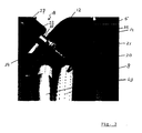
- eine detaillierte perspektivische Ansicht eines hinteren Eckbereichs eines In- nenraums des Gargeräts der
Figuren 1 und 2 von oben; und - Figur 4:
- eine Querschnittansicht einer Mikrowellenleitstruktur aus dem Gargerät der
Figuren 1-3 .
- FIG. 1:
- a cross-sectional view of a cooking appliance according to the invention from above;
- FIG. 2:
- a longitudinal sectional view of the cooking appliance of
FIG. 1 ; - FIG. 3:
- a detailed perspective view of a rear corner portion of an interior of the cooking appliance of
Figures 1 and 2 from above; and - FIG. 4:
- a cross-sectional view of a Mikrowellenleitstruktur from the cooking appliance of
Figures 1-3 ,
Ein in den
Der Innenraum wird von einem Strömungsleitglied 8 zumindest teilweise in einen Garraum 9 und einen Druckraum 10 unterteilt. Im Garraum 9 ist das Gargut platzierbar. Es kann im Garraum 9 zum Beispiel auch ein Gestell mit Einschüben für Gargutträger (nicht gezeigt) vorgesehen sein.The interior is at least partially subdivided by a flow-guiding
Die linke Seitenwand 6 grenzt den Innenraum von einem Installationsraum 11 ab. Alternativ kann der Installationsraum auch hinter der Rückwand angeordnet sein. In der dargestellten Konfiguration ist es jedoch leichter, eine elektronische Bedieneinrichtung an der Vorderseite des Gargeräts 1 neben der Garraumtür 4 vorzusehen, nämlich im Bereich des Installationsraums 11.The left side wall 6 delimits the interior space from an installation space 11. Alternatively, the installation space can also be arranged behind the rear wall. In the illustrated configuration, however, it is easier to provide an electronic operating device on the front of the cooking appliance 1 next to the
Wie aus den
An einer zum Innenraum hin gerichteten Seite des hinteren Seitenwandteils 12, die hier als Vorderseite bezeichnet wird, sind zwei Helixantennen 14, 15 befestigt oder befestigbar. Bei eingeschalteter Mikrowellenheizung werden Mikrowellen von jeweiligen Magnetrons 16, 17 erzeugt und über Wellenleitstrukturen 18, 19 durch das hintere Seitenwandteil 12 zu den Helixantennen 14, 15 geführt.At a side facing the interior of the rear
Aus der
In der
Aufgrund dieser Strahlungscharakteristik ist es nützlich, dass mehrere Helixantennen 14, 15 vorgesehen sind und dass sie auf unterschiedlichen Höhen angeordnet sind. So wird in allen Ebenen Mikrowellenenergie in den Druckraum 10 eingespeist.Because of this radiation characteristic, it is useful to have a plurality of
Die Helixantenne 14 kann alternativ zu einem stabförmigen Antennenteil 21, das sich parallel zu der Längsachse der Helixantenne 14 erstreckt, vorgesehen sein.The
Bei dem in
Der erste Abschnitt 25 geht über eine Gewindebuchse 26 in einen Rechteckhohlleiter 27 über. An einer ersten flachen Wand 28 des Rechteckhohlleiters 27 kann das (in der
Wie aus den
Zum Fixieren des Innenleiters 22 und zur Abdichtung des Inneren des ersten Abschnitts 25 der Mikrowellenleitstruktur 18 ist eine Scheibe 34 aus dielektrischem Material, z.B: Steatit, Teflon oder Glas (wie Pyrex), vorgesehen. Die Scheibe 34 weist eine Nut 35, in der eine (nicht dargestellte) Runddichtung anordbar ist, auf. Dadurch, dass die Helixantenne 14 stationär am hinteren Seitenwandteil 12 befestigt ist, ist diese Dichtung einfacher vorzunehmen, als es bei einer drehbaren Antenne der Fall wäre.For fixing the
Wie aus den
Das Strömungsleitglied 8 ist aus Mikrowellen reflektierendem Material gefertigt oder mit einem solchen Material beschichtet. Es können für Mikrowellen durchlässige, aber luftdichte Fenster im Strömungsleitglied 8 vorgesehen sein. Die Mikrowellenenergie kann auf jeden Fall über die Öffnungen 40 im Randbereich des Strömungsleitglieds 8 vom Druckraum 10 in den Garraum 9 gelangen. Durch diese Gestaltung bilden der Druckraum 10 und der Garraum 9 gekoppelte Resonatoren. Daher ist auch mit nur zwei Helixantennen 14, 15 eine gute Verteilung der Mikrowellenenergie, insbesondere im Betrieb des Radiallüfterrads 36, erreichbar.The
Die Verteilung der Mikrowellenenergie wird auch dadurch verbessert, dass das Radiallüfterrad 36 zumindest teilweise aus Mikrowellen reflektierendem Material hergestellt ist. Es fungiert deshalb als Modenmischer, so dass die Bildung stehender Wellen im Druckraum 10 unterdrückt wird. Durch die Anordnung der Helixantennen 14, 15 seitlich des Radiallüfterrads 36 an der Vorderseite des Seitenwandteils 12, das schräg zur Rückwand 5 steht, ist die emittierte Mikrowellenenergie vorwiegend auf den zentralen Bereich des Druckraums 10 gerichtet.The distribution of the microwave energy is also improved by making the
Dank der oben erwähnten Maßnahmen zur besseren Verteilung der Mikrowellenergie genügt es, dass nur am hinteren Seitenwandteil 12 Helixantennen 14, 15 angeordnet sind. In einer alternativen Ausführungsform könnten jedoch auch am vorderen Seitenwandteil 13 Antennen angeordnet sein.Thanks to the above-mentioned measures for better distribution of the microwave energy, it is sufficient that only at the rear
Durch die Anordnung der Helixantennen 14, 15 an dem hinteren Seitenwandteil 12, das schräg zur linken Seitenwand 6 und zur Rückwand 5 steht, wird der Installationsraum 11 vergrößert, ohne dass dies die Funktion des Druckraums 10 und des Radiallüfterrads 36 beeinträchtigt und ohne die Breite des Garraums 9 zu reduzieren. Die Gesamtbreite des Gargeräts 1 bleibt jedoch verhältnismäßig gering. Die Magnetrons 16, 17 und Wellenleitstrukturen 18, 19 finden neben mehreren weiteren Einrichtungen zur Behandlung von Gargut im Installationsraum 11 Platz.By arranging the
Es steht auch der Geometrie des Gargeräts, unabhängig von der Art der verwendeten Antennen und des Vorhandenseins des Radiallüfterrads, selbständige Bedeutung zu, nämlich wenn das Gargerät einen Innenraum, der einen Garraum zur Aufnahme von Gargut umfasst und durch zumindest eine Wand und/oder zumindest ein Wandteil abgegrenzt ist, und Mittel zum Generieren von Mikrowellen und zum Führen der Mikrowellen zu zumindest einer Antenne umfasst, wobei zumindest eine erste Wand über ein Wandteil in eine zweite Wand übergeht, sich zumindest imaginäre Verlängerungen der beiden Wände auf der vom Innenraum abgewandten Hinterseite des Wandteils schneiden, und zumindest eine der Antennen an der dem Innenraum zugewandten Vorderseite des Wandteils angebracht oder anbringbar ist. Diese Geometrie führt nämlich zu einem besonders kompakten Aufbau.It is also the geometry of the cooking appliance, regardless of the type of antennas used and the presence of the radial fan, independent meaning, namely, when the cooking appliance an interior, which includes a cooking chamber for receiving food and by at least one wall and / or at least one Wall part is delimited, and comprises means for generating microwaves and for guiding the microwaves to at least one antenna, wherein at least a first wall passes over a wall part in a second wall, at least imaginary extensions of the two walls on the side facing away from the interior rear side of the wall part cut, and at least one of the antennas attached to the interior facing the front of the wall part or attachable. This geometry leads to a particularly compact design.
- 11
- GargerätCooking appliance
- 22
- Deckeblanket
- 33
- Bodenflächefloor area
- 44
- Garraumtüroven door
- 55
- Rückwandrear wall
- 66
- Linke SeitenwandLeft sidewall
- 77
- Rechte SeitenwandRight side wall
- 88th
- Strömungsleitgliedflow directing
- 99
- Garraumoven
- 1010
- Druckraumpressure chamber
- 1111
- Installationsrauminstallation space
- 1212
- Hinteres SeitenwandteilRear side wall part
- 1313
- Vorderes SeitenwandteilFront side wall part
- 1414
- Obere HelixantenneUpper helix antenna
- 1515
- Untere HelixantenneLower helical antenna
- 1616
- Oberes MagnetronUpper magnetron
- 1717
- Unteres MagnetronLower magnetron
- 1818
- Obere WellenleitstrukturUpper waveguide structure
- 1919
- Untere WellenleitstrukturLower waveguide structure
- 2020
- Spiralförmiger LeiterSpiral-shaped conductor
- 2121
- Stabförmiges AntennenteilRod-shaped antenna part
- 2222
- Innenleiterinner conductor
- 2323
- Runde WandRound wall
- 2424
- Kupplungclutch
- 2525
- 1. Abschnitt1st section
- 2626
- Gewindebuchsethreaded bushing
- 2727
- RechteckhohlleiterRectangular waveguide
- 2828
- 1. Wand des Rechteckhohlleiters1. Wall of the rectangular waveguide
- 2929
- Gewindethread
- 3030
- 2. Wand des Rechteckhohlleiters2. Wall of the rectangular waveguide
- 3131
- Flanschflange
- 3232
- ÜberwurfmutterNut
- 3333
- Flachdichtunggasket
- 3434
- Scheibedisc
- 3535
- Nutgroove
- 3636
- Radiallüfterradradial fan
- 3737
- Antriebswelledrive shaft
- 3838
- Motorengine
- 3939
- Öffnungopening
- 4040
- Öffnungen im RandbereichOpenings in the edge area
- 4141
- EinspritzeinrichtungInjector
- 4242
- Heizeinrichtungheater
- 4343
- Heizelementeheating elements
Claims (9)
- A cooking device (1) comprising:an interior space which comprises a cooking chamber (9) for receiving items to be cooked; and means (16, 17, 18, 19) for generating microwaves and for guiding said microwaves to at least one aerial (14, 15) that is circularly or elliptically polarized and is arranged to emit the microwaves into the interior space along a direct path, characterized in thata fan wheel (36) which is separated from the aerial (14, 15) and at least partially reflects microwaves is arranged so as to be rotatable in the interior space and serves to circulate the atmosphere in the interior space and to uniform the microwave power distribution in the interior space.
- A cooking device according to claim 1, characterized in that
the interior space is delimited by at least one wall (2, 3, 5, 6, 7) and/or at least one wall part (12, 13), and
the aerial (14, 15) is arranged on a front side of one of the walls (2, 3, 5, 6, 7) or one of the wall parts (12, 13), which front side faces the interior space, wherein
in particular at least one first wall (5) changes to a second wall (6) via a wall part (12), extensions of the two walls (5, 6) intersect on a rear side of the wall part (12), which rear side faces away from the interior space, and
the aerial (14, 15) is mounted to a front side of the wall part (12), which front side faces the interior space. - A cooking device according to claim 2, characterized in that
the fan wheel (36) is arranged on the first or the second wall (5, 6), and/or
at least one of the first and second walls (5, 6) forms a rear wall or side wall of the interior space, and/or
the extensions of the two walls (5, 6) are imaginary extensions. - A cooking device according to any one of the preceding claims, characterized in that
at least two aerials (14, 15) are arranged in the cooking device (1) on different levels, preferably one below the other, in particular one aerial (14) is located above the axis of rotation of the fan wheel (36) and the other aerial (15) is located below the axis of rotation of the fan wheel (36), and/or
the fan wheel (36) is designed as a centrifugal fan wheel. - A cooking device according to any one of the preceding claims, characterized in that
each aerial (14, 15) comprises a conductor (20) including at least one winding which extends about a longitudinal axis that is aligned or can be aligned in the direction of the interior space, in particular a helical aerial. - A cooking device according to any one of the preceding claims, characterized in that
the interior space is at least partially divided into a pressure chamber (10) and the cooking chamber (9) by a flow guide member (8),
the fan wheel (36) and each aerial (14, 15) are located in the pressure chamber (10), and
the flow guide member (8) has an opening (39), which is in particular arranged centrally, in a suction area of the fan wheel (36) and leaves at least one air-permeable opening, which is in particular slit-shaped, on at least one edge. - A cooking device according to any one of claims 2 to 6, characterized in that
the means for guiding the microwaves comprise at least one microwave guide structure (18, 19) which is substantially located outside the interior space and includes a portion (25) extending at least to an opening in the wall (2, 3, 5, 6, 7) or the wall part (12), wherein
in particular the portion (25) comprises a solid, conductive outer wall (23, 24) having a round, in particular circular, cross-sectional shape and/or a coaxial wave conductor including an inner conductor (22) which can be connected or is connected to a conductor (20) of the aerial (14, 15) that is arranged on the front side of the wall or the wall part (12). - A cooking device according to claim 7, characterized in that
the inner conductor (22) extends to a hollow conductor which is comprised by the microwave guide structure (18, 19) and in which in particular at least one aerial of at least one magnetron (16, 17) extends. - A cooking device according to any one of the preceding claims, characterized in that
at least one further device (41, 42, 43) for the treatment of items to be cooked is provided, wherein
the further device is in particular an electric or gas-fired heater (42, 43), a heat exchanger, a device for removing humidity and/or a device for supplying humidity.
Priority Applications (2)
| Application Number | Priority Date | Filing Date | Title |
|---|---|---|---|
| AT08291070T ATE524950T1 (en) | 2008-11-17 | 2008-11-17 | COOKING APPARATUS WITH MICROWAVE POWER |
| EP08291070A EP2187703B1 (en) | 2008-11-17 | 2008-11-17 | Cooking device with microwave feed |
Applications Claiming Priority (1)
| Application Number | Priority Date | Filing Date | Title |
|---|---|---|---|
| EP08291070A EP2187703B1 (en) | 2008-11-17 | 2008-11-17 | Cooking device with microwave feed |
Publications (2)
| Publication Number | Publication Date |
|---|---|
| EP2187703A1 EP2187703A1 (en) | 2010-05-19 |
| EP2187703B1 true EP2187703B1 (en) | 2011-09-14 |
Family
ID=40640262
Family Applications (1)
| Application Number | Title | Priority Date | Filing Date |
|---|---|---|---|
| EP08291070A Active EP2187703B1 (en) | 2008-11-17 | 2008-11-17 | Cooking device with microwave feed |
Country Status (2)
| Country | Link |
|---|---|
| EP (1) | EP2187703B1 (en) |
| AT (1) | ATE524950T1 (en) |
Families Citing this family (2)
| Publication number | Priority date | Publication date | Assignee | Title |
|---|---|---|---|---|
| DE102017105320A1 (en) * | 2017-03-14 | 2018-09-20 | Vorwerk & Co. Interholding Gmbh | System for preparing at least one food |
| DE102022109511A1 (en) | 2022-04-20 | 2023-10-26 | Muegge Gmbh | Device for supplying microwaves into a treatment room |
Family Cites Families (2)
| Publication number | Priority date | Publication date | Assignee | Title |
|---|---|---|---|---|
| US4596915A (en) | 1985-05-07 | 1986-06-24 | Amana Refrigeration, Inc. | Microwave oven having resonant antenna |
| KR100290708B1 (en) | 1997-10-09 | 2001-09-22 | 구자홍 | Uniform heating assembly of microwave oven |
-
2008
- 2008-11-17 EP EP08291070A patent/EP2187703B1/en active Active
- 2008-11-17 AT AT08291070T patent/ATE524950T1/en active
Also Published As
| Publication number | Publication date |
|---|---|
| EP2187703A1 (en) | 2010-05-19 |
| ATE524950T1 (en) | 2011-09-15 |
Similar Documents
| Publication | Publication Date | Title |
|---|---|---|
| DE69010848T2 (en) | Combined microwave and forced convection oven. | |
| DE10106164B4 (en) | microwave oven | |
| DE3310703A1 (en) | MICROWAVE COOKER | |
| DE2622173A1 (en) | DEVICE FOR HEATING AN OBJECT WITH HIGH FREQUENCY RADIATION, IN PARTICULAR MICROWAVE OVEN | |
| DE69703801T2 (en) | ELECTRIC COOKER | |
| DE69934279T2 (en) | Microwave oven provided with halogen lamps | |
| DE3117709A1 (en) | MICROWAVE FEEDING DEVICE FOR MICROWAVE OVENS | |
| EP2187703B1 (en) | Cooking device with microwave feed | |
| DE2844128C2 (en) | Microwave oven | |
| EP2187700B1 (en) | Cooking device and method for emitting microwaves inside a cooking device | |
| DE3308732A1 (en) | HIGH FREQUENCY HEATING UNIT WITH A ROTATING ANTENNA | |
| CH629054A5 (en) | HIGH FREQUENCY HEATER. | |
| DE68903347T2 (en) | MICROWAVE OVEN. | |
| CH639807A5 (en) | Combined oven for microwave and resistance heating. | |
| DE3781301T2 (en) | MICROWAVE OVEN WITH FIELD DISTRIBUTION ELEMENT. | |
| DE3621108C2 (en) | ||
| DE3331432C2 (en) | ||
| DE3326514A1 (en) | Radio-frequency heating apparatus | |
| DE2921990C3 (en) | Microwave oven | |
| EP2187699B1 (en) | Cooking apparatus and method to provide microwaves inside the cavity of said cooking apparatus | |
| EP3643141A1 (en) | Microwave cooking device having a patch antenna | |
| EP2187702A1 (en) | Cooking device with microwave heating | |
| EP3536125B1 (en) | Household cooking appliance | |
| DE3039886C2 (en) | High frequency heater | |
| DE3030627C2 (en) | Arrangement for coupling a rotating antenna to a high-frequency line, in particular for high-frequency heating devices |
Legal Events
| Date | Code | Title | Description |
|---|---|---|---|
| PUAI | Public reference made under article 153(3) epc to a published international application that has entered the european phase |
Free format text: ORIGINAL CODE: 0009012 |
|
| AK | Designated contracting states |
Kind code of ref document: A1 Designated state(s): AT BE BG CH CY CZ DE DK EE ES FI FR GB GR HR HU IE IS IT LI LT LU LV MC MT NL NO PL PT RO SE SI SK TR |
|
| AX | Request for extension of the european patent |
Extension state: AL BA MK RS |
|
| 17P | Request for examination filed |
Effective date: 20100922 |
|
| AKX | Designation fees paid |
Designated state(s): AT BE BG CH CY CZ DE DK EE ES FI FR GB GR HR HU IE IS IT LI LT LU LV MC MT NL NO PL PT RO SE SI SK TR |
|
| GRAP | Despatch of communication of intention to grant a patent |
Free format text: ORIGINAL CODE: EPIDOSNIGR1 |
|
| GRAS | Grant fee paid |
Free format text: ORIGINAL CODE: EPIDOSNIGR3 |
|
| GRAA | (expected) grant |
Free format text: ORIGINAL CODE: 0009210 |
|
| AK | Designated contracting states |
Kind code of ref document: B1 Designated state(s): AT BE BG CH CY CZ DE DK EE ES FI FR GB GR HR HU IE IS IT LI LT LU LV MC MT NL NO PL PT RO SE SI SK TR |
|
| REG | Reference to a national code |
Ref country code: GB Ref legal event code: FG4D Free format text: NOT ENGLISH |
|
| REG | Reference to a national code |
Ref country code: CH Ref legal event code: EP |
|
| REG | Reference to a national code |
Ref country code: IE Ref legal event code: FG4D Free format text: LANGUAGE OF EP DOCUMENT: GERMAN |
|
| REG | Reference to a national code |
Ref country code: DE Ref legal event code: R096 Ref document number: 502008004865 Country of ref document: DE Effective date: 20111201 |
|
| REG | Reference to a national code |
Ref country code: NL Ref legal event code: VDEP Effective date: 20110914 |
|
| PG25 | Lapsed in a contracting state [announced via postgrant information from national office to epo] |
Ref country code: LT Free format text: LAPSE BECAUSE OF FAILURE TO SUBMIT A TRANSLATION OF THE DESCRIPTION OR TO PAY THE FEE WITHIN THE PRESCRIBED TIME-LIMIT Effective date: 20110914 Ref country code: SE Free format text: LAPSE BECAUSE OF FAILURE TO SUBMIT A TRANSLATION OF THE DESCRIPTION OR TO PAY THE FEE WITHIN THE PRESCRIBED TIME-LIMIT Effective date: 20110914 Ref country code: NO Free format text: LAPSE BECAUSE OF FAILURE TO SUBMIT A TRANSLATION OF THE DESCRIPTION OR TO PAY THE FEE WITHIN THE PRESCRIBED TIME-LIMIT Effective date: 20111214 Ref country code: HR Free format text: LAPSE BECAUSE OF FAILURE TO SUBMIT A TRANSLATION OF THE DESCRIPTION OR TO PAY THE FEE WITHIN THE PRESCRIBED TIME-LIMIT Effective date: 20110914 Ref country code: FI Free format text: LAPSE BECAUSE OF FAILURE TO SUBMIT A TRANSLATION OF THE DESCRIPTION OR TO PAY THE FEE WITHIN THE PRESCRIBED TIME-LIMIT Effective date: 20110914 |
|
| LTIE | Lt: invalidation of european patent or patent extension |
Effective date: 20110914 |
|
| PG25 | Lapsed in a contracting state [announced via postgrant information from national office to epo] |
Ref country code: CY Free format text: LAPSE BECAUSE OF FAILURE TO SUBMIT A TRANSLATION OF THE DESCRIPTION OR TO PAY THE FEE WITHIN THE PRESCRIBED TIME-LIMIT Effective date: 20110914 Ref country code: SI Free format text: LAPSE BECAUSE OF FAILURE TO SUBMIT A TRANSLATION OF THE DESCRIPTION OR TO PAY THE FEE WITHIN THE PRESCRIBED TIME-LIMIT Effective date: 20110914 Ref country code: LV Free format text: LAPSE BECAUSE OF FAILURE TO SUBMIT A TRANSLATION OF THE DESCRIPTION OR TO PAY THE FEE WITHIN THE PRESCRIBED TIME-LIMIT Effective date: 20110914 |
|
| REG | Reference to a national code |
Ref country code: IE Ref legal event code: FD4D |
|
| PG25 | Lapsed in a contracting state [announced via postgrant information from national office to epo] |
Ref country code: SK Free format text: LAPSE BECAUSE OF FAILURE TO SUBMIT A TRANSLATION OF THE DESCRIPTION OR TO PAY THE FEE WITHIN THE PRESCRIBED TIME-LIMIT Effective date: 20110914 Ref country code: IE Free format text: LAPSE BECAUSE OF FAILURE TO SUBMIT A TRANSLATION OF THE DESCRIPTION OR TO PAY THE FEE WITHIN THE PRESCRIBED TIME-LIMIT Effective date: 20110914 Ref country code: IS Free format text: LAPSE BECAUSE OF FAILURE TO SUBMIT A TRANSLATION OF THE DESCRIPTION OR TO PAY THE FEE WITHIN THE PRESCRIBED TIME-LIMIT Effective date: 20120114 Ref country code: CZ Free format text: LAPSE BECAUSE OF FAILURE TO SUBMIT A TRANSLATION OF THE DESCRIPTION OR TO PAY THE FEE WITHIN THE PRESCRIBED TIME-LIMIT Effective date: 20110914 |
|
| BERE | Be: lapsed |
Owner name: TOPINOX SARL Effective date: 20111130 |
|
| PG25 | Lapsed in a contracting state [announced via postgrant information from national office to epo] |
Ref country code: IT Free format text: LAPSE BECAUSE OF FAILURE TO SUBMIT A TRANSLATION OF THE DESCRIPTION OR TO PAY THE FEE WITHIN THE PRESCRIBED TIME-LIMIT Effective date: 20110914 Ref country code: PT Free format text: LAPSE BECAUSE OF FAILURE TO SUBMIT A TRANSLATION OF THE DESCRIPTION OR TO PAY THE FEE WITHIN THE PRESCRIBED TIME-LIMIT Effective date: 20120116 Ref country code: EE Free format text: LAPSE BECAUSE OF FAILURE TO SUBMIT A TRANSLATION OF THE DESCRIPTION OR TO PAY THE FEE WITHIN THE PRESCRIBED TIME-LIMIT Effective date: 20110914 Ref country code: PL Free format text: LAPSE BECAUSE OF FAILURE TO SUBMIT A TRANSLATION OF THE DESCRIPTION OR TO PAY THE FEE WITHIN THE PRESCRIBED TIME-LIMIT Effective date: 20110914 Ref country code: NL Free format text: LAPSE BECAUSE OF FAILURE TO SUBMIT A TRANSLATION OF THE DESCRIPTION OR TO PAY THE FEE WITHIN THE PRESCRIBED TIME-LIMIT Effective date: 20110914 Ref country code: RO Free format text: LAPSE BECAUSE OF FAILURE TO SUBMIT A TRANSLATION OF THE DESCRIPTION OR TO PAY THE FEE WITHIN THE PRESCRIBED TIME-LIMIT Effective date: 20110914 |
|
| PG25 | Lapsed in a contracting state [announced via postgrant information from national office to epo] |
Ref country code: MC Free format text: LAPSE BECAUSE OF NON-PAYMENT OF DUE FEES Effective date: 20111130 |
|
| PLBE | No opposition filed within time limit |
Free format text: ORIGINAL CODE: 0009261 |
|
| STAA | Information on the status of an ep patent application or granted ep patent |
Free format text: STATUS: NO OPPOSITION FILED WITHIN TIME LIMIT |
|
| PG25 | Lapsed in a contracting state [announced via postgrant information from national office to epo] |
Ref country code: DK Free format text: LAPSE BECAUSE OF FAILURE TO SUBMIT A TRANSLATION OF THE DESCRIPTION OR TO PAY THE FEE WITHIN THE PRESCRIBED TIME-LIMIT Effective date: 20110914 |
|
| REG | Reference to a national code |
Ref country code: FR Ref legal event code: ST Effective date: 20120731 |
|
| 26N | No opposition filed |
Effective date: 20120615 |
|
| PG25 | Lapsed in a contracting state [announced via postgrant information from national office to epo] |
Ref country code: BE Free format text: LAPSE BECAUSE OF NON-PAYMENT OF DUE FEES Effective date: 20111130 |
|
| REG | Reference to a national code |
Ref country code: DE Ref legal event code: R097 Ref document number: 502008004865 Country of ref document: DE Effective date: 20120615 |
|
| PG25 | Lapsed in a contracting state [announced via postgrant information from national office to epo] |
Ref country code: FR Free format text: LAPSE BECAUSE OF NON-PAYMENT OF DUE FEES Effective date: 20111130 |
|
| PG25 | Lapsed in a contracting state [announced via postgrant information from national office to epo] |
Ref country code: MT Free format text: LAPSE BECAUSE OF FAILURE TO SUBMIT A TRANSLATION OF THE DESCRIPTION OR TO PAY THE FEE WITHIN THE PRESCRIBED TIME-LIMIT Effective date: 20110914 |
|
| PG25 | Lapsed in a contracting state [announced via postgrant information from national office to epo] |
Ref country code: ES Free format text: LAPSE BECAUSE OF FAILURE TO SUBMIT A TRANSLATION OF THE DESCRIPTION OR TO PAY THE FEE WITHIN THE PRESCRIBED TIME-LIMIT Effective date: 20111225 |
|
| PG25 | Lapsed in a contracting state [announced via postgrant information from national office to epo] |
Ref country code: LU Free format text: LAPSE BECAUSE OF NON-PAYMENT OF DUE FEES Effective date: 20111117 |
|
| PG25 | Lapsed in a contracting state [announced via postgrant information from national office to epo] |
Ref country code: BG Free format text: LAPSE BECAUSE OF FAILURE TO SUBMIT A TRANSLATION OF THE DESCRIPTION OR TO PAY THE FEE WITHIN THE PRESCRIBED TIME-LIMIT Effective date: 20111214 |
|
| REG | Reference to a national code |
Ref country code: CH Ref legal event code: PL |
|
| PG25 | Lapsed in a contracting state [announced via postgrant information from national office to epo] |
Ref country code: CH Free format text: LAPSE BECAUSE OF NON-PAYMENT OF DUE FEES Effective date: 20121130 Ref country code: LI Free format text: LAPSE BECAUSE OF NON-PAYMENT OF DUE FEES Effective date: 20121130 |
|
| PG25 | Lapsed in a contracting state [announced via postgrant information from national office to epo] |
Ref country code: TR Free format text: LAPSE BECAUSE OF FAILURE TO SUBMIT A TRANSLATION OF THE DESCRIPTION OR TO PAY THE FEE WITHIN THE PRESCRIBED TIME-LIMIT Effective date: 20110914 |
|
| PG25 | Lapsed in a contracting state [announced via postgrant information from national office to epo] |
Ref country code: HU Free format text: LAPSE BECAUSE OF FAILURE TO SUBMIT A TRANSLATION OF THE DESCRIPTION OR TO PAY THE FEE WITHIN THE PRESCRIBED TIME-LIMIT Effective date: 20110914 |
|
| PG25 | Lapsed in a contracting state [announced via postgrant information from national office to epo] |
Ref country code: GR Free format text: LAPSE BECAUSE OF FAILURE TO SUBMIT A TRANSLATION OF THE DESCRIPTION OR TO PAY THE FEE WITHIN THE PRESCRIBED TIME-LIMIT Effective date: 20110914 |
|
| REG | Reference to a national code |
Ref country code: AT Ref legal event code: MM01 Ref document number: 524950 Country of ref document: AT Kind code of ref document: T Effective date: 20131117 |
|
| PG25 | Lapsed in a contracting state [announced via postgrant information from national office to epo] |
Ref country code: AT Free format text: LAPSE BECAUSE OF NON-PAYMENT OF DUE FEES Effective date: 20131117 |
|
| P01 | Opt-out of the competence of the unified patent court (upc) registered |
Effective date: 20230619 |
|
| PGFP | Annual fee paid to national office [announced via postgrant information from national office to epo] |
Ref country code: GB Payment date: 20231123 Year of fee payment: 16 |
|
| PGFP | Annual fee paid to national office [announced via postgrant information from national office to epo] |
Ref country code: DE Payment date: 20231120 Year of fee payment: 16 |