EP2187588A1 - Decision feedback equalizer for portable communication devices - Google Patents
Decision feedback equalizer for portable communication devices Download PDFInfo
- Publication number
- EP2187588A1 EP2187588A1 EP09175569A EP09175569A EP2187588A1 EP 2187588 A1 EP2187588 A1 EP 2187588A1 EP 09175569 A EP09175569 A EP 09175569A EP 09175569 A EP09175569 A EP 09175569A EP 2187588 A1 EP2187588 A1 EP 2187588A1
- Authority
- EP
- European Patent Office
- Prior art keywords
- equalizer
- taps
- static
- dynamic
- delay
- Prior art date
- Legal status (The legal status is an assumption and is not a legal conclusion. Google has not performed a legal analysis and makes no representation as to the accuracy of the status listed.)
- Granted
Links
- 238000004891 communication Methods 0.000 title claims description 24
- 230000003068 static effect Effects 0.000 claims abstract description 60
- 230000001934 delay Effects 0.000 claims abstract description 33
- 238000000034 method Methods 0.000 claims abstract description 25
- 230000006978 adaptation Effects 0.000 claims description 14
- 238000012545 processing Methods 0.000 claims description 4
- 238000000638 solvent extraction Methods 0.000 claims description 2
- 230000015654 memory Effects 0.000 description 9
- 239000002243 precursor Substances 0.000 description 8
- 230000005540 biological transmission Effects 0.000 description 5
- 230000004044 response Effects 0.000 description 5
- 230000000694 effects Effects 0.000 description 3
- 238000002592 echocardiography Methods 0.000 description 2
- 230000006870 function Effects 0.000 description 2
- 238000012986 modification Methods 0.000 description 2
- 230000004048 modification Effects 0.000 description 2
- 230000009467 reduction Effects 0.000 description 2
- RYGMFSIKBFXOCR-UHFFFAOYSA-N Copper Chemical compound [Cu] RYGMFSIKBFXOCR-UHFFFAOYSA-N 0.000 description 1
- 101100458289 Drosophila melanogaster msps gene Proteins 0.000 description 1
- XUIMIQQOPSSXEZ-UHFFFAOYSA-N Silicon Chemical compound [Si] XUIMIQQOPSSXEZ-UHFFFAOYSA-N 0.000 description 1
- 238000007792 addition Methods 0.000 description 1
- 230000008878 coupling Effects 0.000 description 1
- 238000010168 coupling process Methods 0.000 description 1
- 238000005859 coupling reaction Methods 0.000 description 1
- 238000013479 data entry Methods 0.000 description 1
- 238000012217 deletion Methods 0.000 description 1
- 230000037430 deletion Effects 0.000 description 1
- 239000000835 fiber Substances 0.000 description 1
- 230000002093 peripheral effect Effects 0.000 description 1
- 229910052710 silicon Inorganic materials 0.000 description 1
- 239000010703 silicon Substances 0.000 description 1
- 230000001360 synchronised effect Effects 0.000 description 1
- 238000012546 transfer Methods 0.000 description 1
Images



Classifications
-
- H—ELECTRICITY
- H04—ELECTRIC COMMUNICATION TECHNIQUE
- H04L—TRANSMISSION OF DIGITAL INFORMATION, e.g. TELEGRAPHIC COMMUNICATION
- H04L25/00—Baseband systems
- H04L25/02—Details ; arrangements for supplying electrical power along data transmission lines
- H04L25/03—Shaping networks in transmitter or receiver, e.g. adaptive shaping networks
- H04L25/03006—Arrangements for removing intersymbol interference
- H04L25/03012—Arrangements for removing intersymbol interference operating in the time domain
- H04L25/03019—Arrangements for removing intersymbol interference operating in the time domain adaptive, i.e. capable of adjustment during data reception
- H04L25/03057—Arrangements for removing intersymbol interference operating in the time domain adaptive, i.e. capable of adjustment during data reception with a recursive structure
-
- H—ELECTRICITY
- H04—ELECTRIC COMMUNICATION TECHNIQUE
- H04L—TRANSMISSION OF DIGITAL INFORMATION, e.g. TELEGRAPHIC COMMUNICATION
- H04L25/00—Baseband systems
- H04L25/02—Details ; arrangements for supplying electrical power along data transmission lines
- H04L25/03—Shaping networks in transmitter or receiver, e.g. adaptive shaping networks
- H04L25/03006—Arrangements for removing intersymbol interference
- H04L2025/03433—Arrangements for removing intersymbol interference characterised by equaliser structure
- H04L2025/03439—Fixed structures
- H04L2025/03445—Time domain
- H04L2025/03471—Tapped delay lines
- H04L2025/03484—Tapped delay lines time-recursive
- H04L2025/0349—Tapped delay lines time-recursive as a feedback filter
-
- H—ELECTRICITY
- H04—ELECTRIC COMMUNICATION TECHNIQUE
- H04L—TRANSMISSION OF DIGITAL INFORMATION, e.g. TELEGRAPHIC COMMUNICATION
- H04L25/00—Baseband systems
- H04L25/02—Details ; arrangements for supplying electrical power along data transmission lines
- H04L25/03—Shaping networks in transmitter or receiver, e.g. adaptive shaping networks
- H04L25/03006—Arrangements for removing intersymbol interference
- H04L2025/03433—Arrangements for removing intersymbol interference characterised by equaliser structure
- H04L2025/03535—Variable structures
- H04L2025/03547—Switching between time domain structures
- H04L2025/03566—Switching between time domain structures between different tapped delay line structures
Definitions
- Equalizers are known and are in use. Typically, such equalizers are designed for terrestrial environments where long static or quasi-static multipath delays are predominant. These equalizers are not suitable for portable and mobile use such as for notebooks and netbooks. In contrast to roof top antennas that experience primarily static multipaths, portable environments frequently experience time-varying multipaths in addition to the static multipaths.
- Current demodulators employ equalizers having relatively large number of taps to equalize long delay pre and post cursor echoes. However, such equalizers are not suitable to equalize both long static and short dynamic echoes.
- the equalizer comprises a sparse decision-feedback equalizer.
- configuring the equalizer comprises estimating an adaptation constant of a least mean square (LMS) algorithm employed by the equalizer.
- LMS least mean square
- configuring the equalizer comprises estimating a required number of taps of the equalizer to equalize the at least one of the static and dynamic multipaths, and partitioning the required number of taps into first and second set of taps, wherein the first set of taps is to equalize the static multipath delay and the second set of taps is to equalize the dynamic multipath delay.
- configuring the equalizer comprises determining a position for each of the first and second set of taps of the equalizer.
- the method further comprises providing the second set of taps in feedforward and feedback sections of the equalizer to equalize the dynamic multipath delay.
- the number of taps in the second set of taps is less than about 32.
- a position of each of first set of taps is based upon a delay length of the static multipath delay.
- analyzing the received carrier signal comprises comparing a received pseudo-random noise (PN) sequence with a reference sequence to identify the at least one of the static and dynamic multipath delays.
- PN pseudo-random noise
- the dynamic multipath delay corresponds to delay caused by reflection from a plurality of moving objects disposed in proximity of an antenna of the equalizer.
- a communication module comprising a receiver to receive a plurality of carrier signals, a channel estimator to analyze each of the plurality of signals to identify at least one of a static multipath delay and a dynamic multipath delay in the signals, and an equalizer having a plurality of taps, wherein the equalizer is configured based upon the at least one of the static and dynamic multipath delays.
- the channel estimator is to compare a received PN sequence from the receiver with a reference sequence to identify the at least one of the static and dynamic multipath delays.
- the equalizer comprises a first set of taps to equalize the static multipath delay and a second set of taps to equalize the dynamic multipath delay.
- the second set of taps comprises a pre-determined number of taps in a feedforward section and a feedback section of the equalizer to equalize the dynamic multipath delay.
- a position of each of the first set of taps is based upon a delay length of the static and dynamic multipath delays.
- a device comprising a central processing unit, and a communication module comprising, a receiver to receive a plurality of carrier signals, a channel estimator to analyze each of the plurality of carrier signals to identify at least one of a static multipath delay and a dynamic multipath delay in the signals, and an equalizer having a plurality of taps, wherein the equalizer is configured based upon the at least one of the static and dynamic multipath delays.
- the equalizer comprises a first set of taps corresponding to the static multipath delays and a second set of taps corresponding to the dynamic multipath delays.
- the embodiments of the present invention function to provide a decision feedback equalization technique for time varying channels in portable environments.
- the signals received by a receiver are analyzed to identify static and dynamic multipath delays.
- an equalizer is configured based upon the identified static and/or dynamic multipath delays.
- references in the specification to "one embodiment”, “an embodiment”, “an exemplary embodiment”, indicate that the embodiment described may include a particular feature, structure, or characteristic, but every embodiment may not necessarily include the particular feature, structure, or characteristic. Moreover, such phrases are not necessarily referring to the same embodiment. Further, when a particular feature, structure, or characteristic is described in connection with an embodiment, it is submitted that it is within the knowledge of one skilled in the art to affect such feature, structure, or characteristic in connection with other embodiments whether or not explicitly described.
- a carrier signal is received.
- the carrier signal is received through an antenna of a receiver of a communication module.
- the carrier signal includes an advanced television systems committee (ATSC) signal.
- the carrier signal includes a digital multimedia broadcast-terrestrial/handheld (DMB-T/H) signal.
- ATSC advanced television systems committee
- DMB-T/H digital multimedia broadcast-terrestrial/handheld
- the received carrier signal is analyzed to identify at least one of a static multipath delay and a dynamic multipath delay in the signal.
- a received pseudo-random noise (PN) sequence is compared with a reference sequence to identify the at least one of the static and dynamic multipath delays.
- PN pseudo-random noise
- the equalizer 32 is designed to equalize the effect of the channel so that the transmitted signal x(t) 24 is recovered.
- the communication module 28 includes a channel estimator 36 to analyze each of the plurality of received signals 34 to identify at least one of a static multipath delay and a dynamic multipath delay in the signals. Further, the equalizer 32 is configured based upon the at least one of the static and dynamic multipath delays.
- the equalizer 32 includes a sparse decision-feedback equalizer. However, other suitable equalizers may be employed.
- the channel estimator 36 is to analyze each of the plurality of received signals to identify a main path (i.e., a path with the highest power) and multipath delays.
- a received pseudo-random Noise (PN) sequence within the field sync is cross-correlated with a reference pseudo-random Noise sequence.
- the cross-correlation may be refined, normalized and a threshold may be determined. All peaks above the threshold may represent paths with the maximum representing the principal (i.e., main path) and ones to left of the principal are identified as precursors while ones to right of the principal are identified as postcursors.
- the equalizer 32 may be configured to equalize such multipath delays.
- a required number of taps of the equalizer to equalize the static and dynamic multipaths is determined. Further, the required number of taps is partitioned into first and second set of taps (not shown). The first set of taps is provided to equalize the static multipath delay and the second set of taps is provided to equalize the dynamic multipath delay.
- Such equalization technique facilitates reduction in silicon area for the equalizer along with a reduction in the power consumption.
- Fig. 3 illustrates an exemplary dynamic multipath delay profile 50 identified by the channel estimator 36 of the communication system 20 of Fig. 2 .
- a birth-death event is employed to model effects of a moving object (not shown) such as a vehicle proximate to a portable digital television (DTV) receiver platform like a laptop.
- abscissa axis 52 represents time and the ordinate axis 54 represents an exemplary amplitude of the multipath component.
- a reference for a main path is represented by reference numeral 56 and the birth-death multipath event is represented by profile 58.
- the birth-death event 58 occurs at a delay of ⁇ sees relative to the main path 56.
- the birth ramps up from an amplitude of about -20 dB to about 3 dB in a time period of about 0.1 secs, as represented by reference numeral 60.
- the birth-death profile 58 is determined using radar cross section analysis of a large moving vehicle reflector (e.g., truck, bus, etc.) passing in front of a coffee shop window of about 6 feet height at 40 miles/hour vehicle speed.
- the birth and death occurrence rate is assuming about 2000 vehicles per hour per lane for 3 lanes of traffic.
- the amplitude remains steady at 3 dB for about 0.2 sees. Further, the death ramps down from an amplitude of 3 dB to about -20 dB at 0.3 secs.
- the birth-death occurrences follow a Poisson distribution.
- a birth-death delay of about 200 nsec is assumed for an indoor environment which corresponds to a reflecting object at a distance of about 60 meters from the receiver 30 (see Fig. 2 ) of the communication system 20 (see Fig. 2 ).
- the number of taps required for the equalizer 32 would be relatively low.
- an adaptation constant of a least mean square (LMS) algorithm employed by the equalizer 32 is estimated.
- the adaptation constant for the least mean square algorithm is selected based on the number of taps of the equalizer 32 and a received signal power.
- the range of the adaptation constant becomes relatively small.
- equalizer convergence i.e., equalizer tracking with small error
- the total number of taps corresponding to the dynamic multipath delay is relatively small.
- a few taps are provided around the principal tap to equalize the dynamic multipath delay.
- the equalizer 32 is configured based upon the static multipath delay.
- a first set of taps is provided to equalize the static multipath delay, wherein a number of the first set of taps is at least about a number of delays that are required to be equalized.
- the adaptation constant of the least mean square algorithm is determined based upon the number of major static multipath delays rather than the "length" of the static delays.
- the adaptation constant for the dynamic multipath delays is relatively larger than the adaptation constant for the static multipath delay.
- a sparse decision feedback equalizer is employed that allows for a larger value of the adaptation constant due to fewer non-zero taps.
- this improves the convergence and reduces computations for the equalizer.
- only taps at precursor, postcursor and their crossterm locations are set to be non-zero.
- a few non-zero taps about the principal tap are provided to account for the dynamic multipath delays. In the absence of a birth-death event, the non-zero taps about the principal tap will not affect the overall performance of the equalizer.
- H(z) is the channel transfer function.
- a few taps about the precursor, postcursor and the crossterm locations are placed at non-zero to account for effects of any birth-death events on the static multipath delays.
- the number of non-zero taps is estimated based upon the birth-death delay. In certain embodiments, the number of non-zero taps is about 5.
- the communication system 20 described above may be disposed in a computer system, a wireless communicator and a hand-held device.
- Fig. 6 illustrates an embodiment of a computer system 120.
- the computer system 120 includes a bus 122 to which the various components are coupled.
- the bus 122 includes a collection of a plurality of buses such as a system bus, a Peripheral Component Interface Express (PCIe) bus, etc. Representation of these buses as a single bus 122 is provided for ease of illustration, and it should be understood that the system 120 is not so limited.
- PCIe Peripheral Component Interface Express
- the computer system 120 may have any suitable bus architecture and may include any number of combination of buses.
- a processor 124 is coupled to the bus 122.
- the processor 124 may include any suitable processing device or system, including a microprocessor (e.g., a single core or a multi-core processor), a network processor, an application specific integrated circuit (ASIC), a graphics processor (GPU), or a field programmable gate array (FPGA), or any similar device. It should be noted that although Fig. 6 shows a single processor 124, the computer system 120 may include two or more processors.
- the computer system 120 further includes system memory 126 coupled to the bus 122.
- the system memory 126 may include any suitable type and number of memories, such as static random access memory (SRAM), dynamic random access memory (DRAM), synchronous dynamic random access memory (SDRAM), or double data rate DRAM (DDRDRAM).
- SRAM static random access memory
- DRAM dynamic random access memory
- SDRAM synchronous dynamic random access memory
- DDRDRAM double data rate DRAM
- the computer system 120 may further include a read-only memory (ROM) 128 coupled to the bus 122.
- the ROM 128 may store instructions for the processor 124.
- the computer system 120 may also include a storage device (or devices) 130 coupled to the bus 122.
- the storage device 130 includes any suitable non-volatile memory, such as, for example, a hard disk drive.
- the operating system and other programs may be stored in the storage device 130.
- a device 132 for accessing removable storage media e.g., a floppy disk drive or a CD ROM drive
- the computer system 120 may also include one or more Input/Output (I/O) devices 134 coupled to the bus 122.
- I/O devices include keyboards, pointing devices such as a mouse, as well as other data entry devices.
- common output devices include video displays, printing devices, and audio output devices. It will be appreciated that these are but a few examples of the types of I/O devices that may be coupled to the computer system 120.
- the computer system 120 may further comprise a network interface 136 coupled to the bus 122.
- the network interface 136 comprises any suitable hardware, software, or combination of hardware and software that is capable of coupling the system 120 with a network (e.g., a network interface card).
- the network interface 136 may establish a link with the network over any suitable medium (e.g., wireless, copper wire, fiber optic, or a combination thereof) supporting exchange of information via any suitable protocol such as TCP/IP (Transmission Control protocol/Internet Protocol), HTTP (Hyper-Text Transmission Protocol, as well as others.
- TCP/IP Transmission Control protocol/Internet Protocol
- HTTP Hyper-Text Transmission Protocol
- the computer system 120 illustrated in Fig. 6 is intended to represent an embodiment of such a system and, further, that this system may include any additional components, which have been omitted for clarity and ease of understanding.
- the system 120 may include a direct memory access (DMA) controller, a chip set associated with the processor 124, additional memory (e.g., cache memory) as well as additional signal lines and buses.
- additional memory e.g., cache memory
- the computer system 120 may not include all the components shown in Fig. 6 .
- the computer system 120 may comprise any type of computing device, such as a desktop computer, a laptop computer, a server, a hand-held computing device, a wireless communication device, an entertainment system etc.
- the computer system 120 may include the communication system as described in the embodiments above.
- the computer system 120 may include a receiver to receive a plurality of carrier signals and a channel estimator to analyze each of the plurality of signals to identify at least one of a static multipath delay and a dynamic multipath delay in the signals.
- the computer system 120 may also include an equalizer having a plurality of taps, wherein the equalizer is configured based upon the at least one of the static and dynamic multipath delays.
Landscapes
- Engineering & Computer Science (AREA)
- Power Engineering (AREA)
- Computer Networks & Wireless Communication (AREA)
- Signal Processing (AREA)
- Cable Transmission Systems, Equalization Of Radio And Reduction Of Echo (AREA)
Abstract
Description
- Decision feedback equalizers are known and are in use. Typically, such equalizers are designed for terrestrial environments where long static or quasi-static multipath delays are predominant. These equalizers are not suitable for portable and mobile use such as for notebooks and netbooks. In contrast to roof top antennas that experience primarily static multipaths, portable environments frequently experience time-varying multipaths in addition to the static multipaths. Current demodulators employ equalizers having relatively large number of taps to equalize long delay pre and post cursor echoes. However, such equalizers are not suitable to equalize both long static and short dynamic echoes.
- There is provided a method, comprising receiving a carrier signal, analyzing the received carrier signal to identify at least one of a static multipath delay and a dynamic multipath delay in the signal, and configuring an equalizer based upon the at least one of the static and dynamic multipath delays.
- Optionally, the equalizer comprises a sparse decision-feedback equalizer.
- Optionally, configuring the equalizer comprises estimating an adaptation constant of a least mean square (LMS) algorithm employed by the equalizer.
- Optionally, configuring the equalizer comprises estimating a required number of taps of the equalizer to equalize the at least one of the static and dynamic multipaths, and partitioning the required number of taps into first and second set of taps, wherein the first set of taps is to equalize the static multipath delay and the second set of taps is to equalize the dynamic multipath delay.
- Optionally, configuring the equalizer comprises determining a position for each of the first and second set of taps of the equalizer.
- Optionally, the method further comprises providing the second set of taps in feedforward and feedback sections of the equalizer to equalize the dynamic multipath delay.
- Optionally, the number of taps in the second set of taps is less than about 32.
- Optionally, a position of each of first set of taps is based upon a delay length of the static multipath delay.
- Optionally, analyzing the received carrier signal comprises comparing a received pseudo-random noise (PN) sequence with a reference sequence to identify the at least one of the static and dynamic multipath delays.
- Optionally, the dynamic multipath delay corresponds to delay caused by reflection from a plurality of moving objects disposed in proximity of an antenna of the equalizer.
- Optionally, the static multipath delay corresponds to delay caused by reflection from a plurality of static objects.
- There is also provided a communication module, comprising a receiver to receive a plurality of carrier signals, a channel estimator to analyze each of the plurality of signals to identify at least one of a static multipath delay and a dynamic multipath delay in the signals, and an equalizer having a plurality of taps, wherein the equalizer is configured based upon the at least one of the static and dynamic multipath delays.
- Optionally, the channel estimator is to compare a received PN sequence from the receiver with a reference sequence to identify the at least one of the static and dynamic multipath delays.
- Optionally, the equalizer comprises a sparse decision-feedback equalizer (DFE).
- Optionally, the equalizer comprises a first set of taps to equalize the static multipath delay and a second set of taps to equalize the dynamic multipath delay.
- Optionally, the second set of taps comprises a pre-determined number of taps in a feedforward section and a feedback section of the equalizer to equalize the dynamic multipath delay.
- Optionally, a position of each of the first set of taps is based upon a delay length of the static and dynamic multipath delays.
- There is also provided a device, comprising a central processing unit, and a communication module comprising, a receiver to receive a plurality of carrier signals, a channel estimator to analyze each of the plurality of carrier signals to identify at least one of a static multipath delay and a dynamic multipath delay in the signals, and an equalizer having a plurality of taps, wherein the equalizer is configured based upon the at least one of the static and dynamic multipath delays.
- Optionally, the equalizer comprises a first set of taps corresponding to the static multipath delays and a second set of taps corresponding to the dynamic multipath delays.
- Optionally, the device comprises one of a portable computer, a wireless communicator and a hand-held device and wherein the communication module is implemented in software on the central processing unit.
- Features of embodiments of the claimed subject matter will become apparent as the following detailed description proceeds, and upon reference to the drawings, in which like numerals depict like parts, and in which:
-
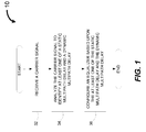
Fig. 1 illustrates an exemplary method for equalization in response to time varying channels in a portable environment in accordance with embodiments of present technique; -
Fig. 2 illustrates an exemplary communication system in accordance with embodiments of present technique; -
Fig. 3 illustrates an exemplary dynamic multipath delay profile identified by the channel estimator of the communication system ofFig. 2 in accordance with embodiments of present technique; -
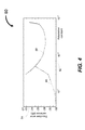
Fig. 4 illustrates an exemplary profile for an equalizer error variance in relation with an adaptation constant for the least mean square algorithm in accordance with embodiments of present technique; -
Fig. 5 illustrates exemplary positions of the taps of the equalizer ofFig. 2 in accordance with embodiments of present technique; and -
Fig. 6 illustrates an embodiment of a computer system. - Although the following Detailed Description will proceed with reference being made to illustrative embodiments of the claimed subject matter, many alternatives, modifications, and variations thereof will be apparent to those skilled in the art. Accordingly, it is intended that the claimed subject matter be viewed broadly, and be defined only as set forth in the accompanying claims.
- As discussed in detail below, the embodiments of the present invention function to provide a decision feedback equalization technique for time varying channels in portable environments. In particular, the signals received by a receiver are analyzed to identify static and dynamic multipath delays. Further, an equalizer is configured based upon the identified static and/or dynamic multipath delays.
- References in the specification to "one embodiment", "an embodiment", "an exemplary embodiment", indicate that the embodiment described may include a particular feature, structure, or characteristic, but every embodiment may not necessarily include the particular feature, structure, or characteristic. Moreover, such phrases are not necessarily referring to the same embodiment. Further, when a particular feature, structure, or characteristic is described in connection with an embodiment, it is submitted that it is within the knowledge of one skilled in the art to affect such feature, structure, or characteristic in connection with other embodiments whether or not explicitly described.
- Referring first to
Fig. 1 , illustrates anexemplary method 10 for equalization in response to time varying channels in a portable environment. At block 12, a carrier signal is received. In this embodiment, the carrier signal is received through an antenna of a receiver of a communication module. In one exemplary embodiment, the carrier signal includes an advanced television systems committee (ATSC) signal. In another exemplary embodiment, the carrier signal includes a digital multimedia broadcast-terrestrial/handheld (DMB-T/H) signal. - At block 14, the received carrier signal is analyzed to identify at least one of a static multipath delay and a dynamic multipath delay in the signal. In one exemplary embodiment, a received pseudo-random noise (PN) sequence is compared with a reference sequence to identify the at least one of the static and dynamic multipath delays. However, other techniques to identify the static and dynamic multipath delays may be envisaged.
- In this exemplary embodiment, the static multipath delay corresponds to delay caused by reflection from a plurality of static objects. Further, the dynamic multipath delay corresponds to delay caused by reflection from a plurality of moving objects disposed in proximity of the antenna. In one exemplary embodiment, the dynamic multipath delay corresponds to delay caused by a moving vehicle caused reflection proximate to a portable digital television (DTV) receiver platform. In one exemplary embodiment, the static multipath delays correspond to reflections caused by far away static objects such as buildings and/or mountains.
- At block 16, an equalizer of the communication module is configured based upon the at least one of the static and dynamic multipath delays. In this exemplary embodiment, the equalizer includes a sparse decision-feedback equalizer. In an exemplary embodiment, a required number of taps of the equalizer to equalize the at least one of the static and dynamic multipaths is estimated. Further, the required number of taps is partitioned into first and second set of taps. The first set of taps is provided to equalize the static multipath delay and the second set of taps is provided to equalize the dynamic multipath delay. In one exemplary embodiment, a position of each of the first and second set of taps is determined.
-
Fig. 2 illustrates anexemplary communication system 20. In the illustrated embodiment, thecommunication system 20 includes atransmitter 22 to transmit a plurality of carrier signals, such as represented byreference numeral 24.Such signals 24 are transmitted through atransmission channel 26 to acommunication module 28. In this exemplary embodiment, thecommunication module 28 includes areceiver 30 to receive the plurality ofsignals 24. The communication module also includes anequalizer 32. Theequalizer 32 is to substantially eliminate any distortions caused by thetransmission channel 26 and front end electronics. - In this exemplary embodiment, a sampled output for a received
signal 34 by thereceiver 30 at an instant k is represented by the following equation:
- x(t) is the transmitted
signal 24; - h(t) is a channel impulse response of the
transmission channel 26; and - y(t) is the received
signal 34; wherein y(t) is represented by the following equation:
- * is the convolution operation; and
- n(t) is the noise or interference.
- In this exemplary embodiment, the
equalizer 32 is designed to equalize the effect of the channel so that the transmitted signal x(t) 24 is recovered. Thecommunication module 28 includes achannel estimator 36 to analyze each of the plurality of receivedsignals 34 to identify at least one of a static multipath delay and a dynamic multipath delay in the signals. Further, theequalizer 32 is configured based upon the at least one of the static and dynamic multipath delays. In this exemplary embodiment, theequalizer 32 includes a sparse decision-feedback equalizer. However, other suitable equalizers may be employed. - The
channel estimator 36 is to analyze each of the plurality of received signals to identify a main path (i.e., a path with the highest power) and multipath delays. In certain embodiments, a received pseudo-random Noise (PN) sequence within the field sync is cross-correlated with a reference pseudo-random Noise sequence. The cross-correlation may be refined, normalized and a threshold may be determined. All peaks above the threshold may represent paths with the maximum representing the principal (i.e., main path) and ones to left of the principal are identified as precursors while ones to right of the principal are identified as postcursors. - Once the main path and multipath delays such as static and dynamic multipath delays are identified, the
equalizer 32 may be configured to equalize such multipath delays. In particular, a required number of taps of the equalizer to equalize the static and dynamic multipaths is determined. Further, the required number of taps is partitioned into first and second set of taps (not shown). The first set of taps is provided to equalize the static multipath delay and the second set of taps is provided to equalize the dynamic multipath delay. Such equalization technique facilitates reduction in silicon area for the equalizer along with a reduction in the power consumption. -
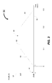
Fig. 3 illustrates an exemplary dynamicmultipath delay profile 50 identified by thechannel estimator 36 of thecommunication system 20 ofFig. 2 . In this exemplary event a birth-death event is employed to model effects of a moving object (not shown) such as a vehicle proximate to a portable digital television (DTV) receiver platform like a laptop. In this embodiment,abscissa axis 52 represents time and theordinate axis 54 represents an exemplary amplitude of the multipath component. - In this embodiment, a reference for a main path is represented by
reference numeral 56 and the birth-death multipath event is represented byprofile 58. As can be seen, the birth-death event 58 occurs at a delay of τ sees relative to themain path 56. In this exemplary event, the birth ramps up from an amplitude of about -20 dB to about 3 dB in a time period of about 0.1 secs, as represented byreference numeral 60. In this embodiment, the birth-death profile 58 is determined using radar cross section analysis of a large moving vehicle reflector (e.g., truck, bus, etc.) passing in front of a coffee shop window of about 6 feet height at 40 miles/hour vehicle speed. The birth and death occurrence rate is assuming about 2000 vehicles per hour per lane for 3 lanes of traffic. - As represented by
reference numeral 62, the amplitude remains steady at 3 dB for about 0.2 sees. Further, the death ramps down from an amplitude of 3 dB to about -20 dB at 0.3 secs. In certain embodiments, the birth-death occurrences follow a Poisson distribution. In this exemplary embodiment, a birth-death delay of about 200 nsec is assumed for an indoor environment which corresponds to a reflecting object at a distance of about 60 meters from the receiver 30 (seeFig. 2 ) of the communication system 20 (seeFig. 2 ). For a symbol duration of about 92.9 sec at an ATSC signal rate of about 10.76 Msps, the number of taps required for the equalizer 32 (seeFig. 2 ) would be relatively low. - In certain embodiments, a plurality of taps (not shown) are provided in the
equalizer 32 to equalize the dynamic multipath delay as described above. In one exemplary embodiment, the plurality of taps are provided in feedforward and feedback sections of theequalizer 32 to equalize the dynamic multipath delay. In one exemplary embodiment, the number of taps is less than about 32. In another exemplary embodiment, the number of taps is about 10. Thus, a pre-determined number of taps may be provided around a principal tap (not shown) of theequalizer 32 to account for time-variable short multipath delays from nearby moving objects such as cars, trucks and people. In operation, when a birth-death event occurs, the tap corresponding to the birth-death delay evolves from zero to a value higher than the principal depending on the birth-death event multipath and then become negligible after the birth-death ramp down. - In one exemplary embodiment, an adaptation constant of a least mean square (LMS) algorithm employed by the
equalizer 32 is estimated. It is noted that the adaptation constant for the least mean square algorithm is selected based on the number of taps of theequalizer 32 and a received signal power. For a dynamic multipath delay event, as the number of taps is increased, the range of the adaptation constant becomes relatively small. As a result, beyond a certain value there may not be equalizer convergence (i.e., equalizer tracking with small error) for the time varying birth-death events. Therefore, the total number of taps corresponding to the dynamic multipath delay is relatively small. In this exemplary embodiment, a few taps are provided around the principal tap to equalize the dynamic multipath delay. - In this exemplary embodiment, the
equalizer 32 is configured based upon the static multipath delay. In particular, a first set of taps is provided to equalize the static multipath delay, wherein a number of the first set of taps is at least about a number of delays that are required to be equalized. Further, the adaptation constant of the least mean square algorithm is determined based upon the number of major static multipath delays rather than the "length" of the static delays. In one embodiment, the adaptation constant for the dynamic multipath delays is relatively larger than the adaptation constant for the static multipath delay. -
Fig. 4 illustrates anexemplary profile 80 for an equalizer error variance in relation with an adaptation constant for the least mean square algorithm. In the illustrated embodiment, theabscissa axis 82 represents the adaptation constant and theordinate axis 84 represents an equalizer error variance (dB). The profile for a conventional equalizer having a large number of taps is represented byreference numeral 86 and the profile for an equalizer designed for a portable mobile channel having a relatively less number of taps is represented byreference numeral 88. As can be seen, the equalizer for the portable mobile channel requires a relatively higher value of the adaptation constant as compared to the conventional equalizer. Further, the conventional equalizer may have an unacceptable increase in the error variance if subjected to the required large portable adaptation constant. - In this exemplary embodiment, a sparse decision feedback equalizer is employed that allows for a larger value of the adaptation constant due to fewer non-zero taps. Advantageously, this improves the convergence and reduces computations for the equalizer. In this exemplary embodiment, only taps at precursor, postcursor and their crossterm locations are set to be non-zero. Further, a few non-zero taps about the principal tap are provided to account for the dynamic multipath delays. In the absence of a birth-death event, the non-zero taps about the principal tap will not affect the overall performance of the equalizer.
- In one exemplary embodiment, the equalizer response is represented by the following equation:




- (β,τβ) is the precursor; and
- (α,τα) is the postcursor.
- Thus, there is a principal tap, a precursor tap, a postcursor tap and a crossterm tap (fourth term in equation 4) in the equalizer. In certain embodiments, second (fifth and sixth terms in the equation 4) and higher order taps may be ignored depending on a magnitude of amplitudes α and β. In one exemplary embodiment, the crossterm for a precursor at about -25 µsecs and a postcursor at about 47 µsecs is estimated as follows: τβ -τα = -25 + 47 = 22 µsecs=237 T/2 spacing = 118.5 T spacing. Where:
- T is a 64- staggered quadrature amplitude modulation (QAM) spacing; and
- T/2 is about 92.9 nsecs.
- In certain embodiments, a few taps about the precursor, postcursor and the crossterm locations are placed at non-zero to account for effects of any birth-death events on the static multipath delays. The number of non-zero taps is estimated based upon the birth-death delay. In certain embodiments, the number of non-zero taps is about 5.
-
Fig. 5 illustratesexemplary positions 100 of the taps of theequalizer 32 ofFig. 2 . In this exemplary embodiment, the precursor and the postcursor taps 102 and 104 are at - 25 µsecs and 47 µsecs respectively. Thefeedforward section 106 is about T/2 spaced and thefeedback section 108 is about T spaced. Further, as described above, thecrossterm 110 is about 118.5 T spaced. - The
communication system 20 described above may be disposed in a computer system, a wireless communicator and a hand-held device.Fig. 6 illustrates an embodiment of acomputer system 120. Thecomputer system 120 includes abus 122 to which the various components are coupled. In certain embodiments, thebus 122 includes a collection of a plurality of buses such as a system bus, a Peripheral Component Interface Express (PCIe) bus, etc. Representation of these buses as asingle bus 122 is provided for ease of illustration, and it should be understood that thesystem 120 is not so limited. Those of ordinary skill in the art will appreciate that thecomputer system 120 may have any suitable bus architecture and may include any number of combination of buses. - A
processor 124 is coupled to thebus 122. Theprocessor 124 may include any suitable processing device or system, including a microprocessor (e.g., a single core or a multi-core processor), a network processor, an application specific integrated circuit (ASIC), a graphics processor (GPU), or a field programmable gate array (FPGA), or any similar device. It should be noted that althoughFig. 6 shows asingle processor 124, thecomputer system 120 may include two or more processors. - The
computer system 120 further includessystem memory 126 coupled to thebus 122. Thesystem memory 126 may include any suitable type and number of memories, such as static random access memory (SRAM), dynamic random access memory (DRAM), synchronous dynamic random access memory (SDRAM), or double data rate DRAM (DDRDRAM). During operation of thecomputer system 120, an operating system and other applications may be resident in thesystem memory 126. - The
computer system 120 may further include a read-only memory (ROM) 128 coupled to thebus 122. TheROM 128 may store instructions for theprocessor 124. Thecomputer system 120 may also include a storage device (or devices) 130 coupled to thebus 122. Thestorage device 130 includes any suitable non-volatile memory, such as, for example, a hard disk drive. The operating system and other programs may be stored in thestorage device 130. Further, a device 132 for accessing removable storage media (e.g., a floppy disk drive or a CD ROM drive) may be coupled to thebus 122. - The
computer system 120 may also include one or more Input/Output (I/O)devices 134 coupled to thebus 122. Common input devices include keyboards, pointing devices such as a mouse, as well as other data entry devices. Further, common output devices include video displays, printing devices, and audio output devices. It will be appreciated that these are but a few examples of the types of I/O devices that may be coupled to thecomputer system 120. - The
computer system 120 may further comprise anetwork interface 136 coupled to thebus 122. Thenetwork interface 136 comprises any suitable hardware, software, or combination of hardware and software that is capable of coupling thesystem 120 with a network (e.g., a network interface card). Thenetwork interface 136 may establish a link with the network over any suitable medium (e.g., wireless, copper wire, fiber optic, or a combination thereof) supporting exchange of information via any suitable protocol such as TCP/IP (Transmission Control protocol/Internet Protocol), HTTP (Hyper-Text Transmission Protocol, as well as others. - It should be understood that the
computer system 120 illustrated inFig. 6 is intended to represent an embodiment of such a system and, further, that this system may include any additional components, which have been omitted for clarity and ease of understanding. By way of example, thesystem 120 may include a direct memory access (DMA) controller, a chip set associated with theprocessor 124, additional memory (e.g., cache memory) as well as additional signal lines and buses. Also, it should be understood that thecomputer system 120 may not include all the components shown inFig. 6 . Thecomputer system 120 may comprise any type of computing device, such as a desktop computer, a laptop computer, a server, a hand-held computing device, a wireless communication device, an entertainment system etc. - In this embodiment, the
computer system 120 may include the communication system as described in the embodiments above. By way of example, thecomputer system 120 may include a receiver to receive a plurality of carrier signals and a channel estimator to analyze each of the plurality of signals to identify at least one of a static multipath delay and a dynamic multipath delay in the signals. Thecomputer system 120 may also include an equalizer having a plurality of taps, wherein the equalizer is configured based upon the at least one of the static and dynamic multipath delays. - The foregoing detailed description and accompanying drawings are only illustrative and not restrictive. They have been provided primarily for a clear and comprehensive understanding of the disclosed embodiments and no unnecessary limitations are to be understood therefrom. Numerous additions, deletions, and modifications to the embodiments described herein, as well as alternative arrangements, may be devised by those skilled in the art without departing from the scope of the appended claims.
Claims (15)
- A method, comprising:receiving a carrier signal;analyzing the received carrier signal to identify at least one of a static multipath delay and a dynamic multipath delay in the signal; andconfiguring an equalizer based upon the at least one of the static and dynamic multipath delays.
- The method of claim 1, wherein the equalizer comprises a sparse decision-feedback equalizer.
- The method of claim 2, wherein configuring the equalizer comprises estimating an adaptation constant of a least mean square (LMS) algorithm employed by the equalizer.
- The method of claim 2, wherein configuring the equalizer comprises:estimating a required number of taps of the equalizer to equalize the at least one of the static and dynamic multipaths; andpartitioning the required number of taps into first and second set of taps, wherein the first set of taps is to equalize the static multipath delay and the second set of taps is to equalize the dynamic multipath delay.
- The method of claim 4, wherein configuring the equalizer comprises determining a position for each of the first and second set of taps of the equalizer.
- The method of claim 4, comprising providing the second set of taps in feedforward and feedback sections of the equalizer to equalize the dynamic multipath delay.
- The method of claim 4, wherein a position of each of first set of taps is based upon a delay length of the static multipath delay.
- The method of claim 1, wherein analyzing the received carrier signal comprises comparing a received pseudo-random noise (PN) sequence with a reference sequence to identify the at least one of the static and dynamic multipath delays.
- The method of claim 1, wherein the dynamic multipath delay corresponds to delay caused by reflection from a plurality of moving objects disposed in proximity of an antenna of the equalizer.
- The method of claim 1, wherein the static multipath delay corresponds to delay caused by reflection from a plurality of static objects.
- A communication module, comprising:a receiver to receive a plurality of carrier signals;a channel estimator to analyze each of the plurality of signals to identify at least one of a static multipath delay and a dynamic multipath delay in the signals; andan equalizer having a plurality of taps, wherein the equalizer is configured based upon the at least one of the static and dynamic multipath delays.
- The communication module of claim 11, wherein the channel estimator is to compare a received PN sequence from the receiver with a reference sequence to identify the at least one of the static and dynamic multipath delays.
- The communication module of claim 11, wherein the equalizer comprises a first set of taps to equalize the static multipath delay and a second set of taps to equalize the dynamic multipath delay.
- The communication module of claim 13, wherein the second set of taps comprises a pre-determined number of taps in a feedforward section and a feedback section of the equalizer to equalize the dynamic multipath delay.
- A device, comprising:a central processing unit; anda communication module according to any of claims 11 to 14.
Applications Claiming Priority (1)
| Application Number | Priority Date | Filing Date | Title |
|---|---|---|---|
| US12/269,606 US8526486B2 (en) | 2008-11-12 | 2008-11-12 | Decision feedback equalizer for portable environments |
Publications (2)
| Publication Number | Publication Date |
|---|---|
| EP2187588A1 true EP2187588A1 (en) | 2010-05-19 |
| EP2187588B1 EP2187588B1 (en) | 2012-02-01 |
Family
ID=41581975
Family Applications (1)
| Application Number | Title | Priority Date | Filing Date |
|---|---|---|---|
| EP09175569A Not-in-force EP2187588B1 (en) | 2008-11-12 | 2009-11-10 | Decision feedback equalizer for portable communication devices |
Country Status (5)
| Country | Link |
|---|---|
| US (1) | US8526486B2 (en) |
| EP (1) | EP2187588B1 (en) |
| JP (1) | JP4901940B2 (en) |
| CN (1) | CN101741780B (en) |
| AT (1) | ATE544278T1 (en) |
Families Citing this family (2)
| Publication number | Priority date | Publication date | Assignee | Title |
|---|---|---|---|---|
| US9769806B2 (en) | 2012-01-17 | 2017-09-19 | Texas Instruments Incorporated | Resource configuration for EPDCCH |
| US10448379B2 (en) * | 2012-05-04 | 2019-10-15 | Texas Instruments Incorporated | Enhanced downlink control channel configuration for LTE |
Citations (3)
| Publication number | Priority date | Publication date | Assignee | Title |
|---|---|---|---|---|
| WO2001097475A1 (en) * | 2000-06-12 | 2001-12-20 | Koninklijke Philips Electronics N.V. | Channel equalizer |
| US20050129143A1 (en) * | 2003-12-12 | 2005-06-16 | Lg Electronics Inc. | Channel equalizing device and method of digital broadcasting receiving system |
| US20050286625A1 (en) * | 2004-06-28 | 2005-12-29 | Jin-Hee Jung | Equalizer capable of adjusting step size and equalization method thereof |
Family Cites Families (12)
| Publication number | Priority date | Publication date | Assignee | Title |
|---|---|---|---|---|
| JPS54149550A (en) * | 1978-05-17 | 1979-11-22 | Toshiba Corp | Automatic equalizer |
| EP0249962B1 (en) * | 1986-06-20 | 1994-05-04 | Hitachi, Ltd. | Digital video signal processor |
| JPS6318812A (en) | 1986-07-11 | 1988-01-26 | Hitachi Ltd | Semiconductor integrated circuit device |
| JPH0831815B2 (en) * | 1988-04-08 | 1996-03-27 | 松下電器産業株式会社 | Adaptive equalizer |
| US5513215A (en) * | 1993-09-20 | 1996-04-30 | Glenayre Electronics, Inc. | High speed simulcast data system using adaptive compensation |
| US5777910A (en) * | 1996-11-19 | 1998-07-07 | Thomson Multimedia S.A. | Sparse equalization filter adaptive in two dimensions |
| KR100505703B1 (en) * | 2003-08-21 | 2005-08-03 | 삼성전자주식회사 | Channel equalizer and channel equalizing method using the same |
| JP4522919B2 (en) * | 2005-07-15 | 2010-08-11 | 三菱電機株式会社 | Equalizer and receiver |
| JP2007201729A (en) | 2006-01-25 | 2007-08-09 | Mitsubishi Electric Corp | Adaptive equalizer and receiver |
| JP2007221629A (en) * | 2006-02-20 | 2007-08-30 | Renesas Technology Corp | Adaptive equalizer |
| US7616685B2 (en) * | 2007-01-19 | 2009-11-10 | Techwell, Inc. | Method for channel tracking in an LMS adaptive equalizer for 8VSB |
| US8798214B2 (en) * | 2007-11-14 | 2014-08-05 | Qualcomm Incorporated | Minimum finger low-power demodulator for wireless communication |
-
2008
- 2008-11-12 US US12/269,606 patent/US8526486B2/en not_active Expired - Fee Related
-
2009
- 2009-11-09 JP JP2009255702A patent/JP4901940B2/en not_active Expired - Fee Related
- 2009-11-10 EP EP09175569A patent/EP2187588B1/en not_active Not-in-force
- 2009-11-10 AT AT09175569T patent/ATE544278T1/en active
- 2009-11-12 CN CN2009102245708A patent/CN101741780B/en not_active Expired - Fee Related
Patent Citations (3)
| Publication number | Priority date | Publication date | Assignee | Title |
|---|---|---|---|---|
| WO2001097475A1 (en) * | 2000-06-12 | 2001-12-20 | Koninklijke Philips Electronics N.V. | Channel equalizer |
| US20050129143A1 (en) * | 2003-12-12 | 2005-06-16 | Lg Electronics Inc. | Channel equalizing device and method of digital broadcasting receiving system |
| US20050286625A1 (en) * | 2004-06-28 | 2005-12-29 | Jin-Hee Jung | Equalizer capable of adjusting step size and equalization method thereof |
Non-Patent Citations (1)
| Title |
|---|
| LINGYAN FAN ET AL: "Efficient robust adaptive decision feedback equalizer for large delay sparse channel", IEEE TRANSACTIONS ON CONSUMER ELECTRONICS, vol. 51, no. 2, 1 May 2005 (2005-05-01), NY, US, pages 449 - 456, XP002388993, ISSN: 0098-3063 * |
Also Published As
| Publication number | Publication date |
|---|---|
| US20100118931A1 (en) | 2010-05-13 |
| US8526486B2 (en) | 2013-09-03 |
| EP2187588B1 (en) | 2012-02-01 |
| CN101741780A (en) | 2010-06-16 |
| JP2010136363A (en) | 2010-06-17 |
| CN101741780B (en) | 2013-08-21 |
| JP4901940B2 (en) | 2012-03-21 |
| ATE544278T1 (en) | 2012-02-15 |
Similar Documents
| Publication | Publication Date | Title |
|---|---|---|
| US9048999B2 (en) | Unequalized clock data recovery for serial I/O receiver | |
| US12200096B2 (en) | Low power edge and data sampling | |
| US10320591B2 (en) | Burst-tolerant decision feedback equalization | |
| US10355890B2 (en) | Repeatable backchannel link adaptation for high speed serial interfaces | |
| US10229081B2 (en) | System level crosstalk mitigation | |
| US10263663B2 (en) | M-ary pulse amplitude modulation digital equalizer | |
| US20160226684A1 (en) | Influence clock data recovery settling point by applying decision feedback equalization to a crossing sample | |
| US8275028B2 (en) | Advanced television systems committee (ATSC) digital television (DTV) receiver | |
| US8526486B2 (en) | Decision feedback equalizer for portable environments | |
| US7020792B2 (en) | Method and apparatus for time domain equalization | |
| US10103910B1 (en) | Pulse amplitude modulation equalization optimization system | |
| US12519680B2 (en) | Receiver and method for controlling equalization | |
| CN108063738B (en) | Convergence decision method for digital equalizer | |
| US10560290B2 (en) | Information handling system half unit interval equalization | |
| CN1559128A (en) | Crosstalk Equalization for Input-Output Driver Circuits | |
| US8229048B2 (en) | Use of emphasis to equalize high speed signal quality |
Legal Events
| Date | Code | Title | Description |
|---|---|---|---|
| PUAI | Public reference made under article 153(3) epc to a published international application that has entered the european phase |
Free format text: ORIGINAL CODE: 0009012 |
|
| AK | Designated contracting states |
Kind code of ref document: A1 Designated state(s): AT BE BG CH CY CZ DE DK EE ES FI FR GB GR HR HU IE IS IT LI LT LU LV MC MK MT NL NO PL PT RO SE SI SK SM TR |
|
| AX | Request for extension of the european patent |
Extension state: AL BA RS |
|
| 17P | Request for examination filed |
Effective date: 20101025 |
|
| 17Q | First examination report despatched |
Effective date: 20101217 |
|
| GRAP | Despatch of communication of intention to grant a patent |
Free format text: ORIGINAL CODE: EPIDOSNIGR1 |
|
| GRAS | Grant fee paid |
Free format text: ORIGINAL CODE: EPIDOSNIGR3 |
|
| GRAA | (expected) grant |
Free format text: ORIGINAL CODE: 0009210 |
|
| AK | Designated contracting states |
Kind code of ref document: B1 Designated state(s): AT BE BG CH CY CZ DE DK EE ES FI FR GB GR HR HU IE IS IT LI LT LU LV MC MK MT NL NO PL PT RO SE SI SK SM TR |
|
| REG | Reference to a national code |
Ref country code: GB Ref legal event code: FG4D |
|
| REG | Reference to a national code |
Ref country code: AT Ref legal event code: REF Ref document number: 544278 Country of ref document: AT Kind code of ref document: T Effective date: 20120215 Ref country code: CH Ref legal event code: EP |
|
| REG | Reference to a national code |
Ref country code: DE Ref legal event code: R096 Ref document number: 602009005017 Country of ref document: DE Effective date: 20120329 |
|
| REG | Reference to a national code |
Ref country code: NL Ref legal event code: VDEP Effective date: 20120201 |
|
| LTIE | Lt: invalidation of european patent or patent extension |
Effective date: 20120201 |
|
| PG25 | Lapsed in a contracting state [announced via postgrant information from national office to epo] |
Ref country code: HR Free format text: LAPSE BECAUSE OF FAILURE TO SUBMIT A TRANSLATION OF THE DESCRIPTION OR TO PAY THE FEE WITHIN THE PRESCRIBED TIME-LIMIT Effective date: 20120201 Ref country code: NL Free format text: LAPSE BECAUSE OF FAILURE TO SUBMIT A TRANSLATION OF THE DESCRIPTION OR TO PAY THE FEE WITHIN THE PRESCRIBED TIME-LIMIT Effective date: 20120201 Ref country code: LT Free format text: LAPSE BECAUSE OF FAILURE TO SUBMIT A TRANSLATION OF THE DESCRIPTION OR TO PAY THE FEE WITHIN THE PRESCRIBED TIME-LIMIT Effective date: 20120201 Ref country code: NO Free format text: LAPSE BECAUSE OF FAILURE TO SUBMIT A TRANSLATION OF THE DESCRIPTION OR TO PAY THE FEE WITHIN THE PRESCRIBED TIME-LIMIT Effective date: 20120501 Ref country code: IS Free format text: LAPSE BECAUSE OF FAILURE TO SUBMIT A TRANSLATION OF THE DESCRIPTION OR TO PAY THE FEE WITHIN THE PRESCRIBED TIME-LIMIT Effective date: 20120601 |
|
| PG25 | Lapsed in a contracting state [announced via postgrant information from national office to epo] |
Ref country code: LV Free format text: LAPSE BECAUSE OF FAILURE TO SUBMIT A TRANSLATION OF THE DESCRIPTION OR TO PAY THE FEE WITHIN THE PRESCRIBED TIME-LIMIT Effective date: 20120201 Ref country code: PL Free format text: LAPSE BECAUSE OF FAILURE TO SUBMIT A TRANSLATION OF THE DESCRIPTION OR TO PAY THE FEE WITHIN THE PRESCRIBED TIME-LIMIT Effective date: 20120201 Ref country code: FI Free format text: LAPSE BECAUSE OF FAILURE TO SUBMIT A TRANSLATION OF THE DESCRIPTION OR TO PAY THE FEE WITHIN THE PRESCRIBED TIME-LIMIT Effective date: 20120201 Ref country code: PT Free format text: LAPSE BECAUSE OF FAILURE TO SUBMIT A TRANSLATION OF THE DESCRIPTION OR TO PAY THE FEE WITHIN THE PRESCRIBED TIME-LIMIT Effective date: 20120601 Ref country code: BE Free format text: LAPSE BECAUSE OF FAILURE TO SUBMIT A TRANSLATION OF THE DESCRIPTION OR TO PAY THE FEE WITHIN THE PRESCRIBED TIME-LIMIT Effective date: 20120201 Ref country code: GR Free format text: LAPSE BECAUSE OF FAILURE TO SUBMIT A TRANSLATION OF THE DESCRIPTION OR TO PAY THE FEE WITHIN THE PRESCRIBED TIME-LIMIT Effective date: 20120502 |
|
| REG | Reference to a national code |
Ref country code: AT Ref legal event code: MK05 Ref document number: 544278 Country of ref document: AT Kind code of ref document: T Effective date: 20120201 |
|
| PG25 | Lapsed in a contracting state [announced via postgrant information from national office to epo] |
Ref country code: CY Free format text: LAPSE BECAUSE OF FAILURE TO SUBMIT A TRANSLATION OF THE DESCRIPTION OR TO PAY THE FEE WITHIN THE PRESCRIBED TIME-LIMIT Effective date: 20120201 |
|
| PG25 | Lapsed in a contracting state [announced via postgrant information from national office to epo] |
Ref country code: EE Free format text: LAPSE BECAUSE OF FAILURE TO SUBMIT A TRANSLATION OF THE DESCRIPTION OR TO PAY THE FEE WITHIN THE PRESCRIBED TIME-LIMIT Effective date: 20120201 Ref country code: CZ Free format text: LAPSE BECAUSE OF FAILURE TO SUBMIT A TRANSLATION OF THE DESCRIPTION OR TO PAY THE FEE WITHIN THE PRESCRIBED TIME-LIMIT Effective date: 20120201 Ref country code: SI Free format text: LAPSE BECAUSE OF FAILURE TO SUBMIT A TRANSLATION OF THE DESCRIPTION OR TO PAY THE FEE WITHIN THE PRESCRIBED TIME-LIMIT Effective date: 20120201 Ref country code: RO Free format text: LAPSE BECAUSE OF FAILURE TO SUBMIT A TRANSLATION OF THE DESCRIPTION OR TO PAY THE FEE WITHIN THE PRESCRIBED TIME-LIMIT Effective date: 20120201 Ref country code: DK Free format text: LAPSE BECAUSE OF FAILURE TO SUBMIT A TRANSLATION OF THE DESCRIPTION OR TO PAY THE FEE WITHIN THE PRESCRIBED TIME-LIMIT Effective date: 20120201 Ref country code: SE Free format text: LAPSE BECAUSE OF FAILURE TO SUBMIT A TRANSLATION OF THE DESCRIPTION OR TO PAY THE FEE WITHIN THE PRESCRIBED TIME-LIMIT Effective date: 20120201 |
|
| PG25 | Lapsed in a contracting state [announced via postgrant information from national office to epo] |
Ref country code: SK Free format text: LAPSE BECAUSE OF FAILURE TO SUBMIT A TRANSLATION OF THE DESCRIPTION OR TO PAY THE FEE WITHIN THE PRESCRIBED TIME-LIMIT Effective date: 20120201 Ref country code: IT Free format text: LAPSE BECAUSE OF FAILURE TO SUBMIT A TRANSLATION OF THE DESCRIPTION OR TO PAY THE FEE WITHIN THE PRESCRIBED TIME-LIMIT Effective date: 20120201 |
|
| PLBE | No opposition filed within time limit |
Free format text: ORIGINAL CODE: 0009261 |
|
| STAA | Information on the status of an ep patent application or granted ep patent |
Free format text: STATUS: NO OPPOSITION FILED WITHIN TIME LIMIT |
|
| 26N | No opposition filed |
Effective date: 20121105 |
|
| PG25 | Lapsed in a contracting state [announced via postgrant information from national office to epo] |
Ref country code: AT Free format text: LAPSE BECAUSE OF FAILURE TO SUBMIT A TRANSLATION OF THE DESCRIPTION OR TO PAY THE FEE WITHIN THE PRESCRIBED TIME-LIMIT Effective date: 20120201 |
|
| REG | Reference to a national code |
Ref country code: DE Ref legal event code: R097 Ref document number: 602009005017 Country of ref document: DE Effective date: 20121105 |
|
| PG25 | Lapsed in a contracting state [announced via postgrant information from national office to epo] |
Ref country code: ES Free format text: LAPSE BECAUSE OF FAILURE TO SUBMIT A TRANSLATION OF THE DESCRIPTION OR TO PAY THE FEE WITHIN THE PRESCRIBED TIME-LIMIT Effective date: 20120512 |
|
| PG25 | Lapsed in a contracting state [announced via postgrant information from national office to epo] |
Ref country code: BG Free format text: LAPSE BECAUSE OF FAILURE TO SUBMIT A TRANSLATION OF THE DESCRIPTION OR TO PAY THE FEE WITHIN THE PRESCRIBED TIME-LIMIT Effective date: 20120501 |
|
| REG | Reference to a national code |
Ref country code: IE Ref legal event code: MM4A |
|
| REG | Reference to a national code |
Ref country code: FR Ref legal event code: ST Effective date: 20130731 |
|
| PG25 | Lapsed in a contracting state [announced via postgrant information from national office to epo] |
Ref country code: IE Free format text: LAPSE BECAUSE OF NON-PAYMENT OF DUE FEES Effective date: 20121110 |
|
| PG25 | Lapsed in a contracting state [announced via postgrant information from national office to epo] |
Ref country code: MT Free format text: LAPSE BECAUSE OF FAILURE TO SUBMIT A TRANSLATION OF THE DESCRIPTION OR TO PAY THE FEE WITHIN THE PRESCRIBED TIME-LIMIT Effective date: 20120201 Ref country code: FR Free format text: LAPSE BECAUSE OF NON-PAYMENT OF DUE FEES Effective date: 20121130 |
|
| PG25 | Lapsed in a contracting state [announced via postgrant information from national office to epo] |
Ref country code: MC Free format text: LAPSE BECAUSE OF NON-PAYMENT OF DUE FEES Effective date: 20121130 Ref country code: TR Free format text: LAPSE BECAUSE OF FAILURE TO SUBMIT A TRANSLATION OF THE DESCRIPTION OR TO PAY THE FEE WITHIN THE PRESCRIBED TIME-LIMIT Effective date: 20120201 |
|
| PG25 | Lapsed in a contracting state [announced via postgrant information from national office to epo] |
Ref country code: SM Free format text: LAPSE BECAUSE OF FAILURE TO SUBMIT A TRANSLATION OF THE DESCRIPTION OR TO PAY THE FEE WITHIN THE PRESCRIBED TIME-LIMIT Effective date: 20120201 Ref country code: LU Free format text: LAPSE BECAUSE OF NON-PAYMENT OF DUE FEES Effective date: 20121110 |
|
| REG | Reference to a national code |
Ref country code: CH Ref legal event code: PL |
|
| PG25 | Lapsed in a contracting state [announced via postgrant information from national office to epo] |
Ref country code: HU Free format text: LAPSE BECAUSE OF FAILURE TO SUBMIT A TRANSLATION OF THE DESCRIPTION OR TO PAY THE FEE WITHIN THE PRESCRIBED TIME-LIMIT Effective date: 20091110 Ref country code: LI Free format text: LAPSE BECAUSE OF NON-PAYMENT OF DUE FEES Effective date: 20131130 Ref country code: CH Free format text: LAPSE BECAUSE OF NON-PAYMENT OF DUE FEES Effective date: 20131130 |
|
| PGFP | Annual fee paid to national office [announced via postgrant information from national office to epo] |
Ref country code: GB Payment date: 20141105 Year of fee payment: 6 |
|
| PG25 | Lapsed in a contracting state [announced via postgrant information from national office to epo] |
Ref country code: MK Free format text: LAPSE BECAUSE OF FAILURE TO SUBMIT A TRANSLATION OF THE DESCRIPTION OR TO PAY THE FEE WITHIN THE PRESCRIBED TIME-LIMIT Effective date: 20120201 |
|
| GBPC | Gb: european patent ceased through non-payment of renewal fee |
Effective date: 20151110 |
|
| PG25 | Lapsed in a contracting state [announced via postgrant information from national office to epo] |
Ref country code: GB Free format text: LAPSE BECAUSE OF NON-PAYMENT OF DUE FEES Effective date: 20151110 |
|
| PGFP | Annual fee paid to national office [announced via postgrant information from national office to epo] |
Ref country code: DE Payment date: 20191029 Year of fee payment: 11 |
|
| REG | Reference to a national code |
Ref country code: DE Ref legal event code: R119 Ref document number: 602009005017 Country of ref document: DE |
|
| PG25 | Lapsed in a contracting state [announced via postgrant information from national office to epo] |
Ref country code: DE Free format text: LAPSE BECAUSE OF NON-PAYMENT OF DUE FEES Effective date: 20210601 |