EP2187516B1 - Schaltungsanordnung parallel geschalteter Leistungssteller zur gleichmäßigen Verteilung der Leistungsaufnahme aus dem Wechselspannungsnetz - Google Patents
Schaltungsanordnung parallel geschalteter Leistungssteller zur gleichmäßigen Verteilung der Leistungsaufnahme aus dem Wechselspannungsnetz Download PDFInfo
- Publication number
- EP2187516B1 EP2187516B1 EP08019904.5A EP08019904A EP2187516B1 EP 2187516 B1 EP2187516 B1 EP 2187516B1 EP 08019904 A EP08019904 A EP 08019904A EP 2187516 B1 EP2187516 B1 EP 2187516B1
- Authority
- EP
- European Patent Office
- Prior art keywords
- power controller
- power
- control
- circuit arrangement
- switching means
- Prior art date
- Legal status (The legal status is an assumption and is not a legal conclusion. Google has not performed a legal analysis and makes no representation as to the accuracy of the status listed.)
- Active
Links
Images

Classifications
-
- H—ELECTRICITY
- H02—GENERATION; CONVERSION OR DISTRIBUTION OF ELECTRIC POWER
- H02M—APPARATUS FOR CONVERSION BETWEEN AC AND AC, BETWEEN AC AND DC, OR BETWEEN DC AND DC, AND FOR USE WITH MAINS OR SIMILAR POWER SUPPLY SYSTEMS; CONVERSION OF DC OR AC INPUT POWER INTO SURGE OUTPUT POWER; CONTROL OR REGULATION THEREOF
- H02M5/00—Conversion of AC power input into AC power output, e.g. for change of voltage, for change of frequency, for change of number of phases
- H02M5/02—Conversion of AC power input into AC power output, e.g. for change of voltage, for change of frequency, for change of number of phases without intermediate conversion into DC
- H02M5/04—Conversion of AC power input into AC power output, e.g. for change of voltage, for change of frequency, for change of number of phases without intermediate conversion into DC by static converters
- H02M5/22—Conversion of AC power input into AC power output, e.g. for change of voltage, for change of frequency, for change of number of phases without intermediate conversion into DC by static converters using discharge tubes with control electrode or semiconductor devices with control electrode
-
- H—ELECTRICITY
- H02—GENERATION; CONVERSION OR DISTRIBUTION OF ELECTRIC POWER
- H02J—ELECTRIC POWER NETWORKS; CIRCUIT ARRANGEMENTS OR SYSTEMS FOR SUPPLYING OR DISTRIBUTING ELECTRIC POWER; SYSTEMS FOR STORING ELECTRIC ENERGY
- H02J3/00—Circuit arrangements for AC mains or AC distribution networks
- H02J3/12—Arrangements for adjusting voltage in AC networks by changing a characteristic of the network load
- H02J3/14—Arrangements for adjusting voltage in AC networks by changing a characteristic of the network load by switching loads on to, or off from, the networks, e.g. progressively balanced loading
-
- H—ELECTRICITY
- H02—GENERATION; CONVERSION OR DISTRIBUTION OF ELECTRIC POWER
- H02J—ELECTRIC POWER NETWORKS; CIRCUIT ARRANGEMENTS OR SYSTEMS FOR SUPPLYING OR DISTRIBUTING ELECTRIC POWER; SYSTEMS FOR STORING ELECTRIC ENERGY
- H02J2105/00—Networks for supplying or distributing electric power characterised by their spatial reach or by the load
- H02J2105/10—Local stationary networks having a local or delimited stationary reach
- H02J2105/12—Local stationary networks having a local or delimited stationary reach supplying households or buildings
-
- Y—GENERAL TAGGING OF NEW TECHNOLOGICAL DEVELOPMENTS; GENERAL TAGGING OF CROSS-SECTIONAL TECHNOLOGIES SPANNING OVER SEVERAL SECTIONS OF THE IPC; TECHNICAL SUBJECTS COVERED BY FORMER USPC CROSS-REFERENCE ART COLLECTIONS [XRACs] AND DIGESTS
- Y02—TECHNOLOGIES OR APPLICATIONS FOR MITIGATION OR ADAPTATION AGAINST CLIMATE CHANGE
- Y02B—CLIMATE CHANGE MITIGATION TECHNOLOGIES RELATED TO BUILDINGS, e.g. HOUSING, HOUSE APPLIANCES OR RELATED END-USER APPLICATIONS
- Y02B70/00—Technologies for an efficient end-user side electric power management and consumption
- Y02B70/30—Systems integrating technologies related to power network operation and communication or information technologies for improving the carbon footprint of the management of residential or tertiary loads, i.e. smart grids as climate change mitigation technology in the buildings sector, including also the last stages of power distribution and the control, monitoring or operating management systems at local level
- Y02B70/3225—Demand response systems, e.g. load shedding, peak shaving
-
- Y—GENERAL TAGGING OF NEW TECHNOLOGICAL DEVELOPMENTS; GENERAL TAGGING OF CROSS-SECTIONAL TECHNOLOGIES SPANNING OVER SEVERAL SECTIONS OF THE IPC; TECHNICAL SUBJECTS COVERED BY FORMER USPC CROSS-REFERENCE ART COLLECTIONS [XRACs] AND DIGESTS
- Y04—INFORMATION OR COMMUNICATION TECHNOLOGIES HAVING AN IMPACT ON OTHER TECHNOLOGY AREAS
- Y04S—SYSTEMS INTEGRATING TECHNOLOGIES RELATED TO POWER NETWORK OPERATION, COMMUNICATION OR INFORMATION TECHNOLOGIES FOR IMPROVING THE ELECTRICAL POWER GENERATION, TRANSMISSION, DISTRIBUTION, MANAGEMENT OR USAGE, i.e. SMART GRIDS
- Y04S20/00—Management or operation of end-user stationary applications or the last stages of power distribution; Controlling, monitoring or operating thereof
- Y04S20/20—End-user application control systems
- Y04S20/222—Demand response systems, e.g. load shedding, peak shaving
Definitions
- the present invention relates to a circuit arrangement with at least two power controllers according to claim 1, each having a power input for connecting the power controller in parallel to an AC power network, at least one load output for connecting loads that can be supplied via the power controller with electrical energy from the AC mains and with controllable switching means for connecting the mains input to the load output (s).
- each power controller has control means for controlling the switching means, the control means being adapted and arranged to drive the switching means during a cycle for the duration of one or more periods of mains voltage to switch a connection between the mains input and the load output or load outputs so adjust the specified power or electrical energy to the loads.
- the invention further relates to a method for operating such a circuit arrangement according to claim 7.
- the publication DE 22 28 709 discloses a circuit arrangement and a method with which it is possible to ensure that electric heaters are turned on one after the other, each remaining on until a desired temperature in the by the switched-on heating is heated space is reached. When the temperature is reached, the next heater in the next room is switched on. If the temperature is not reached, the other rooms will not be heated.
- the publications DE 34 30 786 A1 and DE 44 37 966 C1 disclose circuit arrangements that operate on the principle of Vollschwingungsbêtung. That is, the loads are turned on within a cycle comprising several mains periods for a number of periods to transport the desired electrical energy from the network to the loads during those periods. The set power then results in the ratio of the switch-on time during a cycle to the entire cycle length.
- the power controllers of a circuit arrangement are switched on at times associated with them within one cycle. For example, if the clock comprises fifty periods, and five power controllers are provided in the circuit, the first power controller is turned on for the first period, the second for the eleventh, third for the twenty-first, fourth for the 41st, and fifth to forty-first.
- the duty cycle then depends on the power to be set.
- the method disclosed in this document requires a higher-level control that the Power controller activates as soon as the switch-on times are reached.
- the method has the disadvantage that it can always come back to switching pauses, which can lead to increased ripple of the withdrawn from the power grid.
- the disclosed method ensures that the switching-on times of the power controllers are as uniform as possible over the entire cycle time.
- the method allows a dynamic adaptation of the switch-on times.
- the adaptation takes place iteratively, ie with each additional cycle there is an adaptation step to equalize the load on the network. Only after the adjustment processes are completed, a uniform network load over the entire cycle time is set.
- the method is therefore not suitable for use with fast changing loads to achieve a uniform network load.
- a high computational effort must be made in order to achieve an even distribution of network load over the entire cycle time.
- the invention an object of the invention to provide a circuit arrangement and a method for operating the circuit arrangement, which can supply electric loads with uniform network load with electrical energy via parallel power controller connected without to a large control engineering effort is necessary.
- a first of the power controller has a control output and a last of the power controller has a control input that the control output of the first power controller and the control input the last power controller are connected to each other at least indirectly, that the control means of the first power controller is adapted and adapted to generate a signal applied to the control output of this power controller first signal when the switching means of this power controller are open or opened and that the control means of the last power controller suitable and is set to control the switching means in this power controller to close when applied to the control input of this power controller, a first signal.
- This circuit arrangement can then be operated according to the invention so that the first power controller and each additional power controller provide a first signal at their control outputs when the switching means in the first power controller or other power controller are opened or opened.
- the power controller of a circuit arrangement according to the invention are set in an order.
- the switching means of the first power controller are closed.
- the loads connected to the power controller are supplied with electrical energy over one or more consecutive periods in accordance with the set reference values.
- the switching means are opened and a first signal is provided at the control output of the first power controller. This first signal is transmitted to the next power controller in the order that it receives via its control input. Due to the first signal of the preceding power controller, the power controller then closes its switching means until the desired set point of power has been transferred to the loads.
- the switching means are opened and provided the first signal at the control output of this power controller and the next successive power controller is activated by this first signal.
- the power controllers or the loads connected to the power controllers are activated one after the other or supplied with electrical energy. An even distribution of power extraction from the grid is achieved.
- the circuit arrangement can have exactly two power controllers, namely the first power controller and the last power controller, wherein the control output of the first power controller and the control input of the last power controller are directly connected to one another.
- the circuit arrangement will have additional power controller.
- These further power controllers have the features of the first power controller and the last one Power controller on. That is, they have a control input and a control output. The control output of the first power controller is connected directly to the control input of one of the further power controller. Immediately means that the control input and the control output are connected to each other without the interposition of any other power controller.
- control output of each of the further power controllers is connected directly to the control input of one of the further power controller or the last power controller.
- the control input of the last power controller is advantageously connected directly to the output of one of the further power controllers.
- the first signal provided at the control output of a power controller may be provided without a break after opening or during opening of the switching means. Alternatively, it is possible that the first signal is provided only after a pause of at least one period of the mains voltage after the opening of the switching means.
- the control means of each further power controller or of the last power controller can trigger switching means of the same power controller for closing, if a first signal is present at the control input of the same power controller.
- the closing of the switching means can take place without a break after the occurrence of the first signal at the control input. It is also possible that the closing of the switching means takes place after a pause of at least one period of the mains voltage after the occurrence of the first signal at the control input.
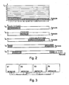
- FIG. 1 shows an example of a method according to the invention, which is carried out with a circuit arrangement according to the invention with ten power controllers S1 to S10. Shown are various profiles of the RMS currents of the entire circuit arrangement (top diagram) and the load currents Is 1 to Is 10 of the individual power controller S1 to S10 of the circuit arrangement according to the invention.
- equal loads are connected to the power controllers S1 to S10.
- the loads are to be supplied with the same electrical energy via the power controllers S1 to S10.
- the RMS currents are therefore identical for the same voltage.
- the diagrams show normalized RMS currents. As a unit of time, a period of oscillation of the mains voltage is selected. Shown are the current courses over a total of fifty periods. Fifty periods correspond to one cycle of the circuit operating on the principle of full swing packet control. Every load attached to one of the Power controller S1 to S10 is connected, is supplied within the time of three periods with electrical energy. The full swing packages therefore have a size of three periods.
- the power supply is evenly distributed, so that the network is as evenly as possible and optimally utilized throughout the cycle.
- the reaction of the circuit arrangement and the loads connected to the circuit arrangement on the supply network can be minimized thereby.
- the power controllers S1 to S10 are switched on for different periods of time so as to supply the loads with electrical energy for different numbers of periods.
- the control of the power controller S1 to S10 is carried out so that at the beginning of the clock, the first power controller S1 always turns on. Only after the power controller S1 is turned off, the next power controller, namely the power controller S2 turns on. Furthermore, each power controller does not switch on until the preceding power controller has been switched off. The power controllers are brought in an order.
- FIG. 2 An example in which the pauses between switching on the power controller and switching through the following power controller is omitted is in FIG. 2 shown.
- the power controllers S1 to S5 are switched through for different lengths of oscillation packets or numbers of periods in order to supply different electrical energy to the loads connected to the power controllers S1 to S5.
- the power controller S1 to S5 are placed in an order, wherein the power controller S1 is the first power controller and S5 is the last power controller.
- the first power controller S1 turns on and supplies the load connected thereto with electrical energy. The supply takes place for a total of fifteen periods. Then the first power controller S1 shuts off.
- the second power controller S2 switches on for a total of ten periods, namely the sixteenth to the twenty-fifth period.
- the loads connected to the second power controller S2 are supplied with lower electrical energy than the loads connected to the first power controller S1.
- the third power controller S3 turns on at the beginning of the twenty-sixth period and stays on until the forty-fifth period.
- the fourth power controller S4 Immediately following the forty-fifth period, the fourth power controller S4 then turns on at the beginning of the forty-sixth period.
- the fourth power controller S4 is to supply the loads connected to the fourth power controller S4 for a total of ten periods, ie for ten full-wave packets with electrical energy.
- the clock has only fifty Periods. This causes the loads connected to the fourth power controller S4 to be turned on for five periods, namely periods forty-six to fifty in one clock and for another five periods, periods one to five in the clock following that clock.
- the first power controller S1 is also turned on at the beginning of the following clock, both the supply of the loads connected to the first power controller S1 and the loads connected to the fourth power controller S4 occur during the first five periods of each clock.
- the loads connected to the fifth power controller S5 must also be supplied with electrical energy. This succeeds in that after switching off the fourth power controller S4 with the end of the fifth period to the beginning of the sixth period of the fifth power controller S5 turns on for a total of ten periods to provide the loads connected to the fifth power controller S5 with electrical energy.
- the electrical power supply of the loads connected to the fifth power controller S5 takes place simultaneously with the power supply of the loads connected to the first power controller S1, which is also switched on for the sixth to fifteenth period.
- FIG. 3 shows four power controllers S1 to S4, wherein the power controller S1, the first power controller and the power controller S4 is the last power controller and the power controller S1 to S4 are placed in an order.
- the power controllers S1 to S4 have control inputs 7 and control outputs 6. In addition, they each have a ground connection 5.
- the ground connections 5 of the power controllers S1 to S4 are connected to one another.
- the power controllers S1 to S4 are designed such that they switch on as soon as a signal is present at the control input 7. The power controllers then remain switched on as long as necessary to reach the setpoint. As soon as the setpoint value is reached, the supply of the loads connected to the power controller is interrupted and a first signal is generated which is made available at the control output 6. Since the control output 6 is connected to the control input 7 of the subsequent power controller S2 to S4, this is then activated. The power controller can provide the required power, and once the desired power has been provided, the power controller shuts off and generates at its control output 6 a first signal. Each power controller S2 to S4 thus always turns on when it is from its previous Power controller S1 to S3 receives a first signal at its control input 7.
- the first power controller S1 receives its first signal to start the power supply of the connected loads from its internal clock control and always at the beginning of a clock.
Landscapes
- Engineering & Computer Science (AREA)
- Power Engineering (AREA)
- Supply And Distribution Of Alternating Current (AREA)
- Direct Current Feeding And Distribution (AREA)
Priority Applications (2)
| Application Number | Priority Date | Filing Date | Title |
|---|---|---|---|
| PL08019904T PL2187516T3 (pl) | 2008-11-14 | 2008-11-14 | Układ połączonych równolegle nastawników mocy do równomiernego rozdzielania poboru mocy z sieci napięcia przemiennego |
| EP08019904.5A EP2187516B1 (de) | 2008-11-14 | 2008-11-14 | Schaltungsanordnung parallel geschalteter Leistungssteller zur gleichmäßigen Verteilung der Leistungsaufnahme aus dem Wechselspannungsnetz |
Applications Claiming Priority (1)
| Application Number | Priority Date | Filing Date | Title |
|---|---|---|---|
| EP08019904.5A EP2187516B1 (de) | 2008-11-14 | 2008-11-14 | Schaltungsanordnung parallel geschalteter Leistungssteller zur gleichmäßigen Verteilung der Leistungsaufnahme aus dem Wechselspannungsnetz |
Publications (2)
| Publication Number | Publication Date |
|---|---|
| EP2187516A1 EP2187516A1 (de) | 2010-05-19 |
| EP2187516B1 true EP2187516B1 (de) | 2014-11-05 |
Family
ID=40577846
Family Applications (1)
| Application Number | Title | Priority Date | Filing Date |
|---|---|---|---|
| EP08019904.5A Active EP2187516B1 (de) | 2008-11-14 | 2008-11-14 | Schaltungsanordnung parallel geschalteter Leistungssteller zur gleichmäßigen Verteilung der Leistungsaufnahme aus dem Wechselspannungsnetz |
Country Status (2)
| Country | Link |
|---|---|
| EP (1) | EP2187516B1 (pl) |
| PL (1) | PL2187516T3 (pl) |
Family Cites Families (4)
| Publication number | Priority date | Publication date | Assignee | Title |
|---|---|---|---|---|
| DE2228709C3 (de) | 1972-06-13 | 1978-06-01 | Tekmar Angewandte Elektronik Gmbh & Co Kg, 4300 Essen | Verfahren und Einrichtung zum Betrieb einer aus mehreren Elektro-Heizgeräten bestehenden Heizungsanlage |
| DE3430786C2 (de) | 1984-08-17 | 1986-07-31 | Licentia Patent-Verwaltungs-Gmbh, 6000 Frankfurt | Schwingungspaketsteuerung von Leistungsstellgliedern mit variabler Taktfrequenz |
| DE4437966C1 (de) | 1994-10-24 | 1995-11-02 | Licentia Gmbh | Verfahren zum Betreiben parallel geschalteter Leistungssteller und Schaltungsanordnung zu seiner Durchführung |
| DE10020865A1 (de) | 2000-04-28 | 2001-11-15 | Aeg Svs Power Supply Systems G | Verfahren zum Betrieb von Leistungsstellern und Schaltungsanordnung zur Durchfuhrung des Verfahrens |
-
2008
- 2008-11-14 EP EP08019904.5A patent/EP2187516B1/de active Active
- 2008-11-14 PL PL08019904T patent/PL2187516T3/pl unknown
Also Published As
| Publication number | Publication date |
|---|---|
| EP2187516A1 (de) | 2010-05-19 |
| PL2187516T3 (pl) | 2015-12-31 |
Similar Documents
| Publication | Publication Date | Title |
|---|---|---|
| AU2002319133B2 (en) | Method for operating a wind energy plant | |
| DE102009021403B4 (de) | Vorrichtung zur Versorgung eines Reaktors mit elektrischer Leistung zum Erzeugen von Siliziumstäben aus Silizium-Dünnstäben nach dem Siemens-Verfahren | |
| EP2864631B1 (de) | Windpark mit mehreren netzeinspeisepunkten | |
| EP2346150A1 (de) | Modulare Spannungsversorgungsanordnung, insbesondere für Reaktoren zur Herstellung von Polysilicium | |
| EP2234259A1 (de) | Vorrichtung zum Zünden und zur Inbetriebnahme von Siliziumstäben | |
| EP1638196B1 (de) | Anordnung zur Versorgung von veränderlichen Lasten | |
| EP3297115B1 (de) | Anordnung mit einer energiespeichereinrichtung und energiewandlereinrichtung zum aufnehmen von elektrischer energie aus einem stromnetz und abgeben von elektrischer energie an das stromnetz | |
| EP3235091B1 (de) | Selektives parallellaufverfahren für mess-/steuergeräte | |
| EP3097624B1 (de) | Wechselrichter, insbesondere als teil eines energieerzeugungsverbundes, und verfahren | |
| DE102010033633A1 (de) | Einschalt-Steuerungsverfahren und Einschalt-Steuerungsvorrichtung | |
| EP2359711A1 (de) | Haarformungs-/Pflegeeinrichtung | |
| EP2362533A1 (de) | Stromversorgungsanordnung, insbesondere zur Versorgung eines Reaktors zur Herstellung von Polysilicium nach dem Siemens-Verfahren | |
| EP3646427B1 (de) | Verfahren und vorrichtung zum elektrischen verbinden eines transformators mit einem elektrischen netz | |
| EP2187516A1 (de) | Schaltungsanordnung parallel geschalteter Leistungssteller zur gleichmäßigen Verteilung der Leistungsaufnahme aus dem Wechselspannungsnetz | |
| EP2385608B1 (de) | Elektromotorischer Möbelantrieb mit einer Energieversorgungseinrichtung | |
| EP3363089B1 (de) | Blindleistungskompensationseinrichtung sowie verfahren zum betreiben einer blindleistungskompensationseinrichtung | |
| EP1018793A2 (de) | Verfahren und Vorrichtung zum Schalten von Verbrauchern eines Elektrogerätes | |
| EP1095543A1 (de) | Vorschaltgerät für mindestens eine gasentladungslampe und verfahren zum betreiben eines derartigen vorschaltgeräts | |
| DE10120497A1 (de) | Elektronisches Vorschaltgerät | |
| DE202004004655U1 (de) | Schaltungsanordnung | |
| DE102015200249A1 (de) | Versorgungsschaltung zur Versorgung eines Schweißgerätes | |
| WO2021037537A1 (de) | Ansteuerverfahren für einen gleichspannungswandler und gleichspannungswandler | |
| EP1426616B1 (de) | Netzkopplung einer Windkraftanlage | |
| DE10160912B4 (de) | Verfahren und Einrichtung zur Steuerung des von mindestens zwei elektrischen Verbrauchern gleicher Leistungsaufnahme, insbesondere Heizkörpern, aufgenommenen Wechselstroms | |
| EP2812990B1 (de) | Ac/dc-spannungswandler und betriebsverfahren hierfür |
Legal Events
| Date | Code | Title | Description |
|---|---|---|---|
| PUAI | Public reference made under article 153(3) epc to a published international application that has entered the european phase |
Free format text: ORIGINAL CODE: 0009012 |
|
| 17P | Request for examination filed |
Effective date: 20091107 |
|
| AK | Designated contracting states |
Kind code of ref document: A1 Designated state(s): AT BE BG CH CY CZ DE DK EE ES FI FR GB GR HR HU IE IS IT LI LT LU LV MC MT NL NO PL PT RO SE SI SK TR |
|
| AX | Request for extension of the european patent |
Extension state: AL BA MK RS |
|
| AKX | Designation fees paid |
Designated state(s): AT BE BG CH CY CZ DE DK EE ES FI FR GB GR HR HU IE IS IT LI LT LU LV MC MT NL NO PL PT RO SE SI SK TR |
|
| 17Q | First examination report despatched |
Effective date: 20120418 |
|
| RAP1 | Party data changed (applicant data changed or rights of an application transferred) |
Owner name: AEG POWER SOLUTIONS GMBH |
|
| GRAP | Despatch of communication of intention to grant a patent |
Free format text: ORIGINAL CODE: EPIDOSNIGR1 |
|
| INTG | Intention to grant announced |
Effective date: 20140516 |
|
| GRAS | Grant fee paid |
Free format text: ORIGINAL CODE: EPIDOSNIGR3 |
|
| GRAA | (expected) grant |
Free format text: ORIGINAL CODE: 0009210 |
|
| AK | Designated contracting states |
Kind code of ref document: B1 Designated state(s): AT BE BG CH CY CZ DE DK EE ES FI FR GB GR HR HU IE IS IT LI LT LU LV MC MT NL NO PL PT RO SE SI SK TR |
|
| REG | Reference to a national code |
Ref country code: GB Ref legal event code: FG4D Free format text: NOT ENGLISH |
|
| REG | Reference to a national code |
Ref country code: CH Ref legal event code: EP |
|
| REG | Reference to a national code |
Ref country code: AT Ref legal event code: REF Ref document number: 695045 Country of ref document: AT Kind code of ref document: T Effective date: 20141115 |
|
| REG | Reference to a national code |
Ref country code: IE Ref legal event code: FG4D Free format text: LANGUAGE OF EP DOCUMENT: GERMAN |
|
| REG | Reference to a national code |
Ref country code: DE Ref legal event code: R096 Ref document number: 502008012369 Country of ref document: DE Effective date: 20141218 |
|
| REG | Reference to a national code |
Ref country code: NL Ref legal event code: VDEP Effective date: 20141105 |
|
| RAP2 | Party data changed (patent owner data changed or rights of a patent transferred) |
Owner name: ADVANCED ENERGY INDUSTRIES GMBH |
|
| REG | Reference to a national code |
Ref country code: LT Ref legal event code: MG4D |
|
| PG25 | Lapsed in a contracting state [announced via postgrant information from national office to epo] |
Ref country code: IS Free format text: LAPSE BECAUSE OF FAILURE TO SUBMIT A TRANSLATION OF THE DESCRIPTION OR TO PAY THE FEE WITHIN THE PRESCRIBED TIME-LIMIT Effective date: 20150305 Ref country code: PT Free format text: LAPSE BECAUSE OF FAILURE TO SUBMIT A TRANSLATION OF THE DESCRIPTION OR TO PAY THE FEE WITHIN THE PRESCRIBED TIME-LIMIT Effective date: 20150305 Ref country code: FI Free format text: LAPSE BECAUSE OF FAILURE TO SUBMIT A TRANSLATION OF THE DESCRIPTION OR TO PAY THE FEE WITHIN THE PRESCRIBED TIME-LIMIT Effective date: 20141105 Ref country code: LT Free format text: LAPSE BECAUSE OF FAILURE TO SUBMIT A TRANSLATION OF THE DESCRIPTION OR TO PAY THE FEE WITHIN THE PRESCRIBED TIME-LIMIT Effective date: 20141105 Ref country code: NO Free format text: LAPSE BECAUSE OF FAILURE TO SUBMIT A TRANSLATION OF THE DESCRIPTION OR TO PAY THE FEE WITHIN THE PRESCRIBED TIME-LIMIT Effective date: 20150205 Ref country code: ES Free format text: LAPSE BECAUSE OF FAILURE TO SUBMIT A TRANSLATION OF THE DESCRIPTION OR TO PAY THE FEE WITHIN THE PRESCRIBED TIME-LIMIT Effective date: 20141105 Ref country code: NL Free format text: LAPSE BECAUSE OF FAILURE TO SUBMIT A TRANSLATION OF THE DESCRIPTION OR TO PAY THE FEE WITHIN THE PRESCRIBED TIME-LIMIT Effective date: 20141105 |
|
| REG | Reference to a national code |
Ref country code: GB Ref legal event code: 732E Free format text: REGISTERED BETWEEN 20150409 AND 20150415 |
|
| REG | Reference to a national code |
Ref country code: DE Ref legal event code: R082 Ref document number: 502008012369 Country of ref document: DE Representative=s name: FRITZ PATENT- UND RECHTSANWAELTE PARTNERSCHAFT, DE |
|
| PG25 | Lapsed in a contracting state [announced via postgrant information from national office to epo] |
Ref country code: GR Free format text: LAPSE BECAUSE OF FAILURE TO SUBMIT A TRANSLATION OF THE DESCRIPTION OR TO PAY THE FEE WITHIN THE PRESCRIBED TIME-LIMIT Effective date: 20150206 Ref country code: CY Free format text: LAPSE BECAUSE OF FAILURE TO SUBMIT A TRANSLATION OF THE DESCRIPTION OR TO PAY THE FEE WITHIN THE PRESCRIBED TIME-LIMIT Effective date: 20141105 Ref country code: LV Free format text: LAPSE BECAUSE OF FAILURE TO SUBMIT A TRANSLATION OF THE DESCRIPTION OR TO PAY THE FEE WITHIN THE PRESCRIBED TIME-LIMIT Effective date: 20141105 Ref country code: SE Free format text: LAPSE BECAUSE OF FAILURE TO SUBMIT A TRANSLATION OF THE DESCRIPTION OR TO PAY THE FEE WITHIN THE PRESCRIBED TIME-LIMIT Effective date: 20141105 Ref country code: HR Free format text: LAPSE BECAUSE OF FAILURE TO SUBMIT A TRANSLATION OF THE DESCRIPTION OR TO PAY THE FEE WITHIN THE PRESCRIBED TIME-LIMIT Effective date: 20141105 |
|
| REG | Reference to a national code |
Ref country code: DE Ref legal event code: R082 Ref document number: 502008012369 Country of ref document: DE Representative=s name: FRITZ PATENT- UND RECHTSANWAELTE PARTNERSCHAFT, DE Effective date: 20150508 Ref country code: DE Ref legal event code: R081 Ref document number: 502008012369 Country of ref document: DE Owner name: ADVANCED ENERGY INDUSTRIES GMBH, DE Free format text: FORMER OWNER: AEG POWER SOLUTIONS GMBH, 59581 WARSTEIN, DE Effective date: 20150508 |
|
| PG25 | Lapsed in a contracting state [announced via postgrant information from national office to epo] |
Ref country code: BE Free format text: LAPSE BECAUSE OF NON-PAYMENT OF DUE FEES Effective date: 20141130 |
|
| REG | Reference to a national code |
Ref country code: CH Ref legal event code: PL |
|
| PG25 | Lapsed in a contracting state [announced via postgrant information from national office to epo] |
Ref country code: LI Free format text: LAPSE BECAUSE OF NON-PAYMENT OF DUE FEES Effective date: 20141130 Ref country code: RO Free format text: LAPSE BECAUSE OF FAILURE TO SUBMIT A TRANSLATION OF THE DESCRIPTION OR TO PAY THE FEE WITHIN THE PRESCRIBED TIME-LIMIT Effective date: 20141105 Ref country code: CZ Free format text: LAPSE BECAUSE OF FAILURE TO SUBMIT A TRANSLATION OF THE DESCRIPTION OR TO PAY THE FEE WITHIN THE PRESCRIBED TIME-LIMIT Effective date: 20141105 Ref country code: SK Free format text: LAPSE BECAUSE OF FAILURE TO SUBMIT A TRANSLATION OF THE DESCRIPTION OR TO PAY THE FEE WITHIN THE PRESCRIBED TIME-LIMIT Effective date: 20141105 Ref country code: EE Free format text: LAPSE BECAUSE OF FAILURE TO SUBMIT A TRANSLATION OF THE DESCRIPTION OR TO PAY THE FEE WITHIN THE PRESCRIBED TIME-LIMIT Effective date: 20141105 Ref country code: CH Free format text: LAPSE BECAUSE OF NON-PAYMENT OF DUE FEES Effective date: 20141130 Ref country code: DK Free format text: LAPSE BECAUSE OF FAILURE TO SUBMIT A TRANSLATION OF THE DESCRIPTION OR TO PAY THE FEE WITHIN THE PRESCRIBED TIME-LIMIT Effective date: 20141105 |
|
| REG | Reference to a national code |
Ref country code: DE Ref legal event code: R097 Ref document number: 502008012369 Country of ref document: DE |
|
| REG | Reference to a national code |
Ref country code: IE Ref legal event code: MM4A |
|
| PG25 | Lapsed in a contracting state [announced via postgrant information from national office to epo] |
Ref country code: MC Free format text: LAPSE BECAUSE OF FAILURE TO SUBMIT A TRANSLATION OF THE DESCRIPTION OR TO PAY THE FEE WITHIN THE PRESCRIBED TIME-LIMIT Effective date: 20141105 |
|
| PLBE | No opposition filed within time limit |
Free format text: ORIGINAL CODE: 0009261 |
|
| STAA | Information on the status of an ep patent application or granted ep patent |
Free format text: STATUS: NO OPPOSITION FILED WITHIN TIME LIMIT |
|
| 26N | No opposition filed |
Effective date: 20150806 |
|
| PG25 | Lapsed in a contracting state [announced via postgrant information from national office to epo] |
Ref country code: IE Free format text: LAPSE BECAUSE OF NON-PAYMENT OF DUE FEES Effective date: 20141114 |
|
| REG | Reference to a national code |
Ref country code: FR Ref legal event code: PLFP Year of fee payment: 8 |
|
| REG | Reference to a national code |
Ref country code: PL Ref legal event code: T3 |
|
| REG | Reference to a national code |
Ref country code: AT Ref legal event code: MM01 Ref document number: 695045 Country of ref document: AT Kind code of ref document: T Effective date: 20141114 |
|
| PG25 | Lapsed in a contracting state [announced via postgrant information from national office to epo] |
Ref country code: SI Free format text: LAPSE BECAUSE OF FAILURE TO SUBMIT A TRANSLATION OF THE DESCRIPTION OR TO PAY THE FEE WITHIN THE PRESCRIBED TIME-LIMIT Effective date: 20141105 Ref country code: AT Free format text: LAPSE BECAUSE OF NON-PAYMENT OF DUE FEES Effective date: 20141114 |
|
| PG25 | Lapsed in a contracting state [announced via postgrant information from national office to epo] |
Ref country code: BG Free format text: LAPSE BECAUSE OF FAILURE TO SUBMIT A TRANSLATION OF THE DESCRIPTION OR TO PAY THE FEE WITHIN THE PRESCRIBED TIME-LIMIT Effective date: 20141105 |
|
| PG25 | Lapsed in a contracting state [announced via postgrant information from national office to epo] |
Ref country code: MT Free format text: LAPSE BECAUSE OF FAILURE TO SUBMIT A TRANSLATION OF THE DESCRIPTION OR TO PAY THE FEE WITHIN THE PRESCRIBED TIME-LIMIT Effective date: 20141105 Ref country code: LU Free format text: LAPSE BECAUSE OF NON-PAYMENT OF DUE FEES Effective date: 20141114 Ref country code: HU Free format text: LAPSE BECAUSE OF FAILURE TO SUBMIT A TRANSLATION OF THE DESCRIPTION OR TO PAY THE FEE WITHIN THE PRESCRIBED TIME-LIMIT; INVALID AB INITIO Effective date: 20081114 Ref country code: TR Free format text: LAPSE BECAUSE OF FAILURE TO SUBMIT A TRANSLATION OF THE DESCRIPTION OR TO PAY THE FEE WITHIN THE PRESCRIBED TIME-LIMIT Effective date: 20141105 |
|
| REG | Reference to a national code |
Ref country code: FR Ref legal event code: PLFP Year of fee payment: 9 |
|
| REG | Reference to a national code |
Ref country code: FR Ref legal event code: PLFP Year of fee payment: 10 |
|
| PGFP | Annual fee paid to national office [announced via postgrant information from national office to epo] |
Ref country code: GB Payment date: 20201104 Year of fee payment: 13 Ref country code: FR Payment date: 20201013 Year of fee payment: 13 Ref country code: IT Payment date: 20201013 Year of fee payment: 13 |
|
| GBPC | Gb: european patent ceased through non-payment of renewal fee |
Effective date: 20211114 |
|
| PG25 | Lapsed in a contracting state [announced via postgrant information from national office to epo] |
Ref country code: GB Free format text: LAPSE BECAUSE OF NON-PAYMENT OF DUE FEES Effective date: 20211114 |
|
| PG25 | Lapsed in a contracting state [announced via postgrant information from national office to epo] |
Ref country code: FR Free format text: LAPSE BECAUSE OF NON-PAYMENT OF DUE FEES Effective date: 20211130 |
|
| PG25 | Lapsed in a contracting state [announced via postgrant information from national office to epo] |
Ref country code: IT Free format text: LAPSE BECAUSE OF NON-PAYMENT OF DUE FEES Effective date: 20211114 |
|
| P01 | Opt-out of the competence of the unified patent court (upc) registered |
Effective date: 20230616 |
|
| PGFP | Annual fee paid to national office [announced via postgrant information from national office to epo] |
Ref country code: DE Payment date: 20250916 Year of fee payment: 18 |
|
| PGFP | Annual fee paid to national office [announced via postgrant information from national office to epo] |
Ref country code: PL Payment date: 20250912 Year of fee payment: 18 |