EP2187221A2 - A unit and method for preparing a sample for the microbiological analysis of a liquid - Google Patents
A unit and method for preparing a sample for the microbiological analysis of a liquid Download PDFInfo
- Publication number
- EP2187221A2 EP2187221A2 EP09290531A EP09290531A EP2187221A2 EP 2187221 A2 EP2187221 A2 EP 2187221A2 EP 09290531 A EP09290531 A EP 09290531A EP 09290531 A EP09290531 A EP 09290531A EP 2187221 A2 EP2187221 A2 EP 2187221A2
- Authority
- EP
- European Patent Office
- Prior art keywords
- filter
- opening
- module
- liquid
- membrane
- Prior art date
- Legal status (The legal status is an assumption and is not a legal conclusion. Google has not performed a legal analysis and makes no representation as to the accuracy of the status listed.)
- Granted
Links
- 239000007788 liquid Substances 0.000 title claims abstract description 107
- 238000000034 method Methods 0.000 title claims abstract description 11
- 238000012543 microbiological analysis Methods 0.000 title claims description 6
- 239000012528 membrane Substances 0.000 claims abstract description 127
- 244000005700 microbiome Species 0.000 claims description 29
- 238000002360 preparation method Methods 0.000 claims description 28
- 239000011148 porous material Substances 0.000 claims description 23
- 238000000926 separation method Methods 0.000 claims description 19
- 230000009089 cytolysis Effects 0.000 claims description 9
- 230000000295 complement effect Effects 0.000 claims description 7
- 230000000717 retained effect Effects 0.000 claims description 7
- 238000004458 analytical method Methods 0.000 claims description 6
- 238000000151 deposition Methods 0.000 claims description 2
- 210000004027 cell Anatomy 0.000 description 12
- 239000003795 chemical substances by application Substances 0.000 description 11
- 230000015572 biosynthetic process Effects 0.000 description 8
- 238000001914 filtration Methods 0.000 description 8
- 230000002934 lysing effect Effects 0.000 description 8
- 238000011109 contamination Methods 0.000 description 7
- 241000894006 Bacteria Species 0.000 description 6
- 244000052616 bacterial pathogen Species 0.000 description 6
- 241000206602 Eukaryota Species 0.000 description 5
- 239000012620 biological material Substances 0.000 description 4
- 239000006166 lysate Substances 0.000 description 4
- 239000002033 PVDF binder Substances 0.000 description 3
- 239000003153 chemical reaction reagent Substances 0.000 description 3
- 238000002955 isolation Methods 0.000 description 3
- 229920002981 polyvinylidene fluoride Polymers 0.000 description 3
- 240000004808 Saccharomyces cerevisiae Species 0.000 description 2
- 241000700605 Viruses Species 0.000 description 2
- 230000003321 amplification Effects 0.000 description 2
- 238000009833 condensation Methods 0.000 description 2
- 230000005494 condensation Effects 0.000 description 2
- 238000001704 evaporation Methods 0.000 description 2
- 230000008020 evaporation Effects 0.000 description 2
- 238000004519 manufacturing process Methods 0.000 description 2
- 238000003199 nucleic acid amplification method Methods 0.000 description 2
- 150000007523 nucleic acids Chemical class 0.000 description 2
- 102000039446 nucleic acids Human genes 0.000 description 2
- 108020004707 nucleic acids Proteins 0.000 description 2
- 230000035945 sensitivity Effects 0.000 description 2
- 241000233866 Fungi Species 0.000 description 1
- 239000004743 Polypropylene Substances 0.000 description 1
- 230000004888 barrier function Effects 0.000 description 1
- 239000013043 chemical agent Substances 0.000 description 1
- 230000006835 compression Effects 0.000 description 1
- 238000007906 compression Methods 0.000 description 1
- 238000009826 distribution Methods 0.000 description 1
- 229920001971 elastomer Polymers 0.000 description 1
- 239000000806 elastomer Substances 0.000 description 1
- 238000011049 filling Methods 0.000 description 1
- 239000012530 fluid Substances 0.000 description 1
- 238000010438 heat treatment Methods 0.000 description 1
- 238000005304 joining Methods 0.000 description 1
- 230000014759 maintenance of location Effects 0.000 description 1
- 210000004962 mammalian cell Anatomy 0.000 description 1
- 230000002906 microbiologic effect Effects 0.000 description 1
- 238000002156 mixing Methods 0.000 description 1
- -1 polypropylene Polymers 0.000 description 1
- 229920001155 polypropylene Polymers 0.000 description 1
- 229920001296 polysiloxane Polymers 0.000 description 1
- 238000011045 prefiltration Methods 0.000 description 1
- 239000007787 solid Substances 0.000 description 1
- 239000000126 substance Substances 0.000 description 1
- 238000002604 ultrasonography Methods 0.000 description 1
- 238000011144 upstream manufacturing Methods 0.000 description 1
- 238000013022 venting Methods 0.000 description 1
- 238000003466 welding Methods 0.000 description 1
Images


Classifications
-
- G—PHYSICS
- G01—MEASURING; TESTING
- G01N—INVESTIGATING OR ANALYSING MATERIALS BY DETERMINING THEIR CHEMICAL OR PHYSICAL PROPERTIES
- G01N1/00—Sampling; Preparing specimens for investigation
- G01N1/28—Preparing specimens for investigation including physical details of (bio-)chemical methods covered elsewhere, e.g. G01N33/50, C12Q
- G01N1/40—Concentrating samples
- G01N1/4077—Concentrating samples by other techniques involving separation of suspended solids
-
- B—PERFORMING OPERATIONS; TRANSPORTING
- B01—PHYSICAL OR CHEMICAL PROCESSES OR APPARATUS IN GENERAL
- B01L—CHEMICAL OR PHYSICAL LABORATORY APPARATUS FOR GENERAL USE
- B01L3/00—Containers or dishes for laboratory use, e.g. laboratory glassware; Droppers
- B01L3/50—Containers for the purpose of retaining a material to be analysed, e.g. test tubes
- B01L3/502—Containers for the purpose of retaining a material to be analysed, e.g. test tubes with fluid transport, e.g. in multi-compartment structures
-
- B—PERFORMING OPERATIONS; TRANSPORTING
- B01—PHYSICAL OR CHEMICAL PROCESSES OR APPARATUS IN GENERAL
- B01L—CHEMICAL OR PHYSICAL LABORATORY APPARATUS FOR GENERAL USE
- B01L2200/00—Solutions for specific problems relating to chemical or physical laboratory apparatus
- B01L2200/02—Adapting objects or devices to another
- B01L2200/026—Fluid interfacing between devices or objects, e.g. connectors, inlet details
-
- B—PERFORMING OPERATIONS; TRANSPORTING
- B01—PHYSICAL OR CHEMICAL PROCESSES OR APPARATUS IN GENERAL
- B01L—CHEMICAL OR PHYSICAL LABORATORY APPARATUS FOR GENERAL USE
- B01L2300/00—Additional constructional details
- B01L2300/04—Closures and closing means
- B01L2300/046—Function or devices integrated in the closure
- B01L2300/049—Valves integrated in closure
-
- B—PERFORMING OPERATIONS; TRANSPORTING
- B01—PHYSICAL OR CHEMICAL PROCESSES OR APPARATUS IN GENERAL
- B01L—CHEMICAL OR PHYSICAL LABORATORY APPARATUS FOR GENERAL USE
- B01L2300/00—Additional constructional details
- B01L2300/06—Auxiliary integrated devices, integrated components
- B01L2300/0681—Filter
-
- B—PERFORMING OPERATIONS; TRANSPORTING
- B01—PHYSICAL OR CHEMICAL PROCESSES OR APPARATUS IN GENERAL
- B01L—CHEMICAL OR PHYSICAL LABORATORY APPARATUS FOR GENERAL USE
- B01L2400/00—Moving or stopping fluids
- B01L2400/04—Moving fluids with specific forces or mechanical means
- B01L2400/0403—Moving fluids with specific forces or mechanical means specific forces
- B01L2400/0409—Moving fluids with specific forces or mechanical means specific forces centrifugal forces
-
- B—PERFORMING OPERATIONS; TRANSPORTING
- B01—PHYSICAL OR CHEMICAL PROCESSES OR APPARATUS IN GENERAL
- B01L—CHEMICAL OR PHYSICAL LABORATORY APPARATUS FOR GENERAL USE
- B01L2400/00—Moving or stopping fluids
- B01L2400/06—Valves, specific forms thereof
- B01L2400/0622—Valves, specific forms thereof distribution valves, valves having multiple inlets and/or outlets, e.g. metering valves, multi-way valves
-
- B—PERFORMING OPERATIONS; TRANSPORTING
- B01—PHYSICAL OR CHEMICAL PROCESSES OR APPARATUS IN GENERAL
- B01L—CHEMICAL OR PHYSICAL LABORATORY APPARATUS FOR GENERAL USE
- B01L2400/00—Moving or stopping fluids
- B01L2400/06—Valves, specific forms thereof
- B01L2400/0633—Valves, specific forms thereof with moving parts
- B01L2400/0644—Valves, specific forms thereof with moving parts rotary valves
-
- B—PERFORMING OPERATIONS; TRANSPORTING
- B01—PHYSICAL OR CHEMICAL PROCESSES OR APPARATUS IN GENERAL
- B01L—CHEMICAL OR PHYSICAL LABORATORY APPARATUS FOR GENERAL USE
- B01L3/00—Containers or dishes for laboratory use, e.g. laboratory glassware; Droppers
- B01L3/50—Containers for the purpose of retaining a material to be analysed, e.g. test tubes
- B01L3/502—Containers for the purpose of retaining a material to be analysed, e.g. test tubes with fluid transport, e.g. in multi-compartment structures
- B01L3/5021—Test tubes specially adapted for centrifugation purposes
-
- G—PHYSICS
- G01—MEASURING; TESTING
- G01N—INVESTIGATING OR ANALYSING MATERIALS BY DETERMINING THEIR CHEMICAL OR PHYSICAL PROPERTIES
- G01N1/00—Sampling; Preparing specimens for investigation
- G01N1/28—Preparing specimens for investigation including physical details of (bio-)chemical methods covered elsewhere, e.g. G01N33/50, C12Q
- G01N1/2813—Producing thin layers of samples on a substrate, e.g. smearing, spinning-on
-
- G—PHYSICS
- G01—MEASURING; TESTING
- G01N—INVESTIGATING OR ANALYSING MATERIALS BY DETERMINING THEIR CHEMICAL OR PHYSICAL PROPERTIES
- G01N1/00—Sampling; Preparing specimens for investigation
- G01N1/28—Preparing specimens for investigation including physical details of (bio-)chemical methods covered elsewhere, e.g. G01N33/50, C12Q
- G01N1/40—Concentrating samples
- G01N1/4077—Concentrating samples by other techniques involving separation of suspended solids
- G01N2001/4088—Concentrating samples by other techniques involving separation of suspended solids filtration
-
- Y—GENERAL TAGGING OF NEW TECHNOLOGICAL DEVELOPMENTS; GENERAL TAGGING OF CROSS-SECTIONAL TECHNOLOGIES SPANNING OVER SEVERAL SECTIONS OF THE IPC; TECHNICAL SUBJECTS COVERED BY FORMER USPC CROSS-REFERENCE ART COLLECTIONS [XRACs] AND DIGESTS
- Y10—TECHNICAL SUBJECTS COVERED BY FORMER USPC
- Y10T—TECHNICAL SUBJECTS COVERED BY FORMER US CLASSIFICATION
- Y10T436/00—Chemistry: analytical and immunological testing
- Y10T436/25—Chemistry: analytical and immunological testing including sample preparation
- Y10T436/25375—Liberation or purification of sample or separation of material from a sample [e.g., filtering, centrifuging, etc.]
- Y10T436/255—Liberation or purification of sample or separation of material from a sample [e.g., filtering, centrifuging, etc.] including use of a solid sorbent, semipermeable membrane, or liquid extraction
-
- Y—GENERAL TAGGING OF NEW TECHNOLOGICAL DEVELOPMENTS; GENERAL TAGGING OF CROSS-SECTIONAL TECHNOLOGIES SPANNING OVER SEVERAL SECTIONS OF THE IPC; TECHNICAL SUBJECTS COVERED BY FORMER USPC CROSS-REFERENCE ART COLLECTIONS [XRACs] AND DIGESTS
- Y10—TECHNICAL SUBJECTS COVERED BY FORMER USPC
- Y10T—TECHNICAL SUBJECTS COVERED BY FORMER US CLASSIFICATION
- Y10T436/00—Chemistry: analytical and immunological testing
- Y10T436/25—Chemistry: analytical and immunological testing including sample preparation
- Y10T436/2575—Volumetric liquid transfer
Definitions
- Such preparation units are provided for inletting a predetermined volume of liquid to analyze into a compartment of that unit, in order to pass that liquid through the membrane and to evacuate the liquid once it has crossed the membrane.
- a unit for preparing a sample for the microbiological analysis of a predetermined volume of liquid that may contain microorganisms
- said filter module comprising an inlet compartment for inletting said predetermined volume by an inlet opening of said filter module, said inlet compartment being adapted to contain the whole of said predetermined volume, as well as an evacuation compartment for evacuating said predetermined volume by an evacuation opening of said filter module to said collection module, said evacuation compartment being separated from said inlet compartment by said membrane, the filter and collection modules being rotatably mounted relative to each other, and having, relative to each other, a first relative predetermined position, in which said evacuation opening of said filter module is in register with a first opening of said collection module and a second relative predetermined position different from said first position, in which said evacuation outlet of said filter module is in register with a second opening of said collection module; characterized in that said inlet and evacuation compartments are on opposite sides from each other relative to said filter
- the inlet compartment for the liquid and the evacuation compartment are on opposite sides from each other relative to the membrane (that is to say on either side of the membrane) thus enables the liquid to flow in a single direction for the entire length of the filtration, so making the unit compatible with the liquid flowing by centrifuging.
- a reagent in the filter module without it flowing through the collection module. It may thus be a chemical lysing agent to perform lysis of the microorganisms retained on the filter membrane. As this agent is unable to flow out, its action is more effective on the microorganisms due to a longer contact time. It is thus possible to use a small volume of that agent which improves the sensitivity of the analyses carried out on the lysate so obtained (as too great a volume of reagent can be a source of background noise in particular for analyses such as methods of nucleic acid amplification.
- said filter module comprises a body within which is fixed said filter membrane as well as a separation membrane that is situated between said inlet opening and said filter membrane, said separation membrane having a pore diameter greater than the pore diameter of said filter membrane.
- the presence of two membranes in the filter module of different pore diameters makes it possible to separate the unwanted microorganisms (for example eukaryote cells, which are of too large a size to pass through the membrane) from the microorganisms to analyze (bacteria or viruses for example) which are collected on the second membrane.
- unwanted microorganisms for example eukaryote cells, which are of too large a size to pass through the membrane
- analyze bacteria or viruses for example
- said filter module comprises another membrane, juxtaposed against said separation membrane, on the opposite side of the separation membrane to the filter membrane, said other membrane having a greater pore diameter than the pore diameter of said separation membrane.
- said filter module comprises another opening formed in said body and giving access to a compartment of said body situated between said separation and filter membranes.
- the preparation unit 1 illustrated in Figures 1 to 13 comprises a filter module 2 and a module 3 for collection of the liquids after they have passed through the filter module.
- the body 7 has an upper portion 8 and a lower portion 9 with one nested in the other.
- Portion 8 has a first cylindrical part 20 delimiting the opening 18 and around which the cover 11 nestingly fits and a second cylindrical part 21 of smaller diameter than the first cylindrical part 20, these parts being connected together by a frusto-conical part 22.
- the cylindrical part 21 is closed, on the opposite side to the frusto-conical part 22 by a wall 23 with the exception of an opening 27 ( Figure 3 ) for passage of the liquid to the following compartment.
- the membranes 4 and 5 (disposed against each other) are sealed against that wall at their perimeter.
- These membranes rest on a region of the wall 23 in which are formed drainage channels for the liquid after having passed through those membranes, the channels being provided to direct the liquid to the passage opening 27.
- the width of the channels (0.4 mm) is chosen so as to provide sufficient drainage of the liquid while ensuring sufficient mechanical support for the membranes 4 and 5 which must resist high pressure stresses in particular in case of filtration by centrifuging.
- portion 8 there is also formed a channel 24 ( Figure 3 ) open at both ends, disposed against the inner face of part 21 and extending beyond that part towards the opening 18.
- the opening 25 of that channel is situated substantially at the level of the opening 18, and is obturated by the cover 11 when it is nestingly fitted around part 20, that channel issuing, by its opposite opening 26 to the opening 25, into the region of the filter module situated between the membrane 6, and the membranes 4 and 5.
- Portion 9 has a cylindrical part 30, a frusto-conical part 31 and a transverse wall 32.
- the cylindrical part 30 is of substantially equal diameter to the diameter of the cylindrical part 21 and has a region 33 of reduced thickness provided to be nestingly fitted by deformation of part 21 and then welded against that part 21 to provide the integrity of the unit relative to leaks on centrifuging but also relative to risks of contamination (in particular when it is not possible to work under an extractor hood).
- the frusto-conical part 31 is connected to the part 30 on the opposite side to that provided to be nestingly fitted into portion 8 and tapers outwardly.
- an indexing fin 35 ( Figure 15 ) also projects, which is provided for cooperating with complementary indexing means on the collection module 3 to hold the filter module relative to the collection module in the desired position.
- the transverse wall 32 extends substantially transversely to the cylindrical part 30 while partially obturating it and joining to the part 30 at approximately half way between its edges.
- This wall has a step formation at its periphery to form a bowl at the bottom of which is sealed the membrane 6 around its perimeter.
- This filter module is thus arranged such that the introduction compartments for the liquid, formed from the compartments 40 and 41, and the evacuation compartment 42 for the liquid are on opposite sides from each other relative to the membrane 6 (that is to say on either side of the membrane 6) so as to enable the liquid to flow in a single direction for the entire length of the filtration, so making the unit compatible with the liquid flowing by centrifuging.
- the collection module 3 comprises a fluid distribution disc 50, a fluid-tight seal 51, as well as a first reservoir 52 and a second reservoir 53 attached on the same side of the disc 50.
- the reservoir 53 has smaller capacity than the reservoir 52, and is a collector tube here of microtube type with 1.5 mL capacity. This reservoir 53 is provided as will be seen below for collecting microorganisms to analyze after having subjected them to lysis on the membrane 6.
- the reservoir 53 has a rim 56 provided for latching cooperation with a collar 81 of the disc 50.
- This disc 50 has a wall 60 in which there are formed two openings 63 and 64 of the same diameter and an opening 65 of markedly smaller diameter than that of the openings 63 and 64, the openings 63, 64 and 65 respectively being surrounded by ribs 66, 67 and 68 projecting from the face 61 of the wall 60 that is situated on the opposite side to the reservoirs 52 and 53.
- the rib 68 surrounding the aperture 65 is circular.
- This disc also comprises three ribs 69, 70 and 71 projecting from that surface 61, each provided to form, as will be seen below, a housing for indexing the position of the collection module relative to the filter module.
- the rib 69 (respectively 71) has a guide portion 72 (respectively 75) for the indexing fin 35 that the filter module comprises, an abutment portion 73 (respectively 76) for that fin and a housing-forming cut-out 74 (respectively 77) for that fin situated between the portions 72 and 73.
- the intermediate rib 70 has two guide portions 78 and 79, and a cut-out 80 between those portions.
- This disc also comprises, projecting from the opposite face 62 to the face 61, an annular collar 81 for latching to the reservoir 53 and an annular collar 82 for centering the reservoir 52 welded against that disc.
- the seal 51 is a seal of elastomer (of silicone in the example illustrated) of bean-shaped longitudinal section in which, in the neighborhood of each end, there is formed a passage duct 90, 91 for the liquid coming from the filter module.
- a passage duct 90, 91 for the liquid coming from the filter module.
- annular groove 92 (respectively 93) formed to accommodate therein the portion of the wall 60 of the disc 50 bordering the opening 63 (respectively 64).
- the duct 90 (respectively 91), as illustrated in Figure 18 , issues on the side of the seal provided to cooperate with the filter module 2 by a first opening 95 (respectively 96) and on the opposite side by a second opening (not visible in the drawings).
- the wall 60 of the disc 50 is received at its periphery in the annular groove 34 of the filter module, such that the filter module is thus rotatably mounted relative to the collection module, the fin 35 of the filter module being provided to be received in one of the cut-outs 74, 77 or 80 of the collection module depending on the step of preparing the sample that is implemented (see below).
- the filter module 2 is thus provided to have three distinct positions relative to the collection module 3 with the fin 35 of the filter module being latched in the corresponding housing for each position.
- the fin 35 is engaged in the cut-out 74 and the collection module is disposed relative to the filter module such that the evacuation opening 19 is situated in register with the opening 95 of the duct 90 of the seal ( Figure 3 ).
- the evacuation compartment 42 is thus placed in communication with the reservoir 52 via the duct 90.
- the liquid poured into the filter module is able to pass through that module to attain reservoir 52 via the membranes 4 and 5, by the membrane 6 next, and then by passing through the opening 19, the opening 95 and lastly the duct 90.
- the fin 35 is in the cut-out 80 and the openings 95 and 96 of the ducts 90 and 91 of the seal are obturated by that wall 32.
- the annular ribs 43 and 44 thus respectively surround the openings 95 and 96 ( Figures 8 and 9 ) of the ducts while exerting a pressure against the seal 51 to ensure the fluid-tight isolation of the reservoirs 52 and 53, this being in order to avoid any risk of contamination by the air which would be liable to pass from one reservoir to the other (by evaporation and/or condensation for example).
- the opening 19 of that wall is also obturated in fluid-tight manner by the portion 94 of the seal that is situated between the ducts 90 and 91 ( Figure 7 ), so preventing the liquid from flowing from the filter module.
- the operator grasps the preparation unit 1 to rotate the filter module 2 relative to the collection module 3 in order to disengage the fin 35 from the cut-out in which it is disposed.
- the portions 72, 75, 78 and 79 of the ribs 69, 71 and 70 participate in guiding the fin to enter the corresponding cut-out while the portions 73 and 76 form abutments for that fin in order to prevent the operator from turning the modules relative to each other beyond the authorized angular positions.
- a preparation unit grasps a preparation unit, and, if it is not already the case, turns the filter module 2 relative to the collection module 3 to position the rib 36 associated with the position "1" on the frusto-conical portion 31 in alignment with the cursor 55 situated on the reservoir 52.
- the operator After having removed the cover 11 in advance, the operator then pours a predetermined volume of liquid to analyze into the compartment 40 of the filter module 2 (for example 20 ml).
- the operator replaces the cover 11 and the preparation unit 1 is then placed in a centrifuge.
- Rotating the centrifuge drives the movement of the liquid such that the predetermined volume passes through the membranes 4 and 5 to occupy the compartment 41 of the filter module.
- the large size of the pores of the membranes 4 and 5 means that when those membranes are wet they allow the air to pass only with a slight pressurization (very slight bubble point phenomenon), such that the air can enter the compartment 41 so enabling the liquid then to pass through the membrane 6 and to flow so as to occupy the compartment 42 and lastly, by passing through the aperture 19 and the duct 90, to reach the collection reservoir 52 for the liquid so filtered.
- the pore diameter of the membrane 5 (here 5 ⁇ m) is chosen such that only the microorganisms of greatest size, here the eukaryotes, are retained by that membrane whereas the other microorganisms, here bacteria (of size well below 5 ⁇ m), pass through it to be collected finally on the membrane 6.
- the membrane 4 which has pores (here 30 ⁇ m) of even greater diameter than those of the membrane 5, is disposed upstream and juxtaposed against the membrane 5 to avoid any risk of clogging of the membrane 5 in case the membrane to filter were to contain a very high number of eukaryote cells to separate from the rest of the liquid.
- the pores of the membrane 6 are of course dimensioned (0.45 ⁇ m in this example) so as to retain the germs which it is desired to detect.
- the reduction in the volume of air in that reservoir does not lead to any pressurization phenomenon in that reservoir due to the presence of the opening 65 forming a vent enabling the reservoir 52 and thus the compartment 42 to be kept at atmospheric pressure, which thus prevents any risk of the membrane 6 doming during the filtration of the liquid.
- vent 12 ( Figure 1 ) formed in the cover 11 ensures the compartments 40 and 41 are kept at atmospheric pressure and thus also prevents the membrane 6 doming, not by pressurization in the compartment 42 but by depressurization in the compartments 40 and 41.
- the operator stops the centrifuge and grasps the preparation unit to perform a movement of relative rotation of the filter module relative to the collection module so as to position the rib 37 situated beside the Figure “2 " on the frusto-conical part 31 of the filter module in alignment with the cursor 55 ( Figure 6 ).
- the operator can then remote the cover 11 to pour into the channel 25 a predetermined volume of a lysing agent (300 ⁇ L for example) which, in flowing through that channel, will reach compartment 41 to cover the upper surface 10 of the membrane 6. After having deposited the lysing agent, the operator then replaces the cover 11.
- a lysing agent 300 ⁇ L for example
- the membrane 6 remains flat which enables the lysing agent to be deposited homogenously and evenly over the whole of the membrane (and not solely at its perimeter which would be the case if the membrane had become domed).
- the operator After having kept the lysing agent in contact with the membrane for that predetermined time (depending on the lysing agent) at a predetermined temperature (for example 60°) in order to increase the effectiveness of the agent, the operator again turns the filter module relative to the collection module to position the rib 38 situated beside the figure "3 " on the frusto-conical part 31 of the filter module in alignment with the cursor 55 ( Figure 10 ).
- a predetermined temperature for example 60°
- the preparation unit is then again placed in the centrifuge to make the lysate (containing the biological material of the bacteria) pass through the equipment 6, that biological material, after having undergone the lysis, being of sufficiently reduced size to pass through the pores of that membrane and thus to be collected in the reservoir 53.
- the operator can then remove the preparation unit from the centrifuge and unlatch the reservoir 53 from the disc 50 to perform an analysis of the lysate collected in that reservoir.
- microorganisms to detect are not necessarily bacteria but may in particular be viruses, yeasts (of sufficiently small size not to be retained by the membranes 4 and 5) or moulds. It may be that the liquid to analyze does not contain eukaryote cells but other types of microorganisms (to separate from the germs to detect) such as yeast or filamentous fungi.
- FIG. 19 Another embodiment of the preparation unit is represented in Figure 19 .
- the preparation unit 101 of Figure 19 is similar to the unit 1 apart from the reservoir 53 being eliminated in this embodiment, the terminal formation 181 of the disc 150 being in this case provided to be connected for example to a hose 157, as illustrated in Figure 19 , leading to a remote reservoir for example.
- the reservoir 152 is similarly replaced.
- FIG. 20 Another embodiment of the preparation unit is represented in Figure 20 .
- the cover 11 is replaced, in particular when it is impossible to work under an extractor hood or in a confined space protected from contaminations, by a cover provided to be welded to the body of the filter module in order to reduce the risk of contamination, that cover then having, in that case, a first terminal formation (of female Luer type for example) to connect a valve by which the volume of liquid to filter is introduced, a second terminal formation, also of female Luer type, to connect a microbiological filter comprising a membrane that forms a barrier to microorganisms (porosity 0.22 ⁇ m) but permeable to the air in order therefore to enable sterile venting of the compartment 40, as well as a third female Luer terminal formation to connect a syringe provided with a male Luer terminal formation, that third terminal formation issuing in the access channel 24 and being obturated by a plug when the syringe is not connected to that terminal formation.
- a first terminal formation of female Luer type for example
- a second terminal formation
Landscapes
- Health & Medical Sciences (AREA)
- Chemical & Material Sciences (AREA)
- Analytical Chemistry (AREA)
- General Health & Medical Sciences (AREA)
- Immunology (AREA)
- Biochemistry (AREA)
- Life Sciences & Earth Sciences (AREA)
- General Physics & Mathematics (AREA)
- Physics & Mathematics (AREA)
- Pathology (AREA)
- Hematology (AREA)
- Clinical Laboratory Science (AREA)
- Chemical Kinetics & Catalysis (AREA)
- Apparatus Associated With Microorganisms And Enzymes (AREA)
- Sampling And Sample Adjustment (AREA)
- Measuring Or Testing Involving Enzymes Or Micro-Organisms (AREA)
Abstract
Description
- The present invention concerns the preparation of a sample for the microbiological analysis of a liquid.
- The preparation of such samples is most commonly carried out by passing a liquid that may contain microorganisms through a preparation unit provided with a filter membrane on which the microorganisms of that liquid are retained if it contains any.
- Such preparation units are provided for inletting a predetermined volume of liquid to analyze into a compartment of that unit, in order to pass that liquid through the membrane and to evacuate the liquid once it has crossed the membrane.
- In some cases is its sometimes necessary also to collect the liquid that has crossed the membrane after having undergone a treatment specific to the microorganisms that it may retain (such as a treatment by lysis of those microorganisms for the purpose of collecting the biological material of those microorganisms for analyses) but without that liquid mixing with the liquid filtered previously.
- A preparation unit is already known from the United States patent
US 6,374,684 comprising a compartment for inletting a liquid to analyze, a plurality of compartments disposed around the inlet compartment, as well as a rotary valve overhanging those compartments and adapted to make those compartments communicate pairwise, either directly, or via a filter membrane that the valve comprises. - A plunger slides in the inlet compartment not only to be able to take off liquid by sucking (by pulling the plunger) from one of the of the compartments surrounding the inlet compartment, but also, after rotation of the valve, to be able to collect that liquid (by pushing the plunger) in another of the compartments surrounding the inlet compartment, either directly, or after that liquid has crossed the filter membrane.
- The invention concerns providing a unit of the same type but which at the same time is more polyvalent and more practical.
- To that end it provides a unit for preparing a sample for the microbiological analysis of a predetermined volume of liquid that may contain microorganisms comprising a filter membrane filter module and a collection module for each liquid coming from said filter module, with said filter module comprising an inlet compartment for inletting said predetermined volume by an inlet opening of said filter module, said inlet compartment being adapted to contain the whole of said predetermined volume, as well as an evacuation compartment for evacuating said predetermined volume by an evacuation opening of said filter module to said collection module, said evacuation compartment being separated from said inlet compartment by said membrane, the filter and collection modules being rotatably mounted relative to each other, and having, relative to each other, a first relative predetermined position, in which said evacuation opening of said filter module is in register with a first opening of said collection module and a second relative predetermined position different from said first position, in which said evacuation outlet of said filter module is in register with a second opening of said collection module; characterized in that said inlet and evacuation compartments are on opposite sides from each other relative to said filter membrane with said inlet compartment being arranged such that, when said predetermined volume is in said inlet compartment, the liquid is in contact with the filter membrane over at least the majority of its surface.
- The arrangement of the inlet and evacuation compartments on the opposite side from each other relative to the filter membrane with the inlet compartment which enables the liquid to be placed in contact with at least the majority of the surface of the membrane gives numerous possibilities for making the liquid flow from the filter module to attain the collection module.
- The flow of the liquid into the preparation unit across the membrane may thus be implemented for example by placing that unit in a centrifuge.
- More particularly, the fact that the inlet compartment for the liquid and the evacuation compartment are on opposite sides from each other relative to the membrane (that is to say on either side of the membrane) thus enables the liquid to flow in a single direction for the entire length of the filtration, so making the unit compatible with the liquid flowing by centrifuging.
- Furthermore, when situated at the level of the inlet compartment, the liquid comes into contact with the membrane over the majority of its surface so giving a large area for liquid passage, the pressure loss thus being rendered small also to enable flow by centrifuging.
- This is an advantage relative to the devices of the prior art, such as those described in particular in the United States patent
US 6,374,684 , which did not provide such a possibility due to the fact that the compartments of those devices are all situated on the same side of the membrane (centrifuging of such devices thus not making it possible to pass the liquid from one compartment to another) and also due to the fact that the liquid of the inlet compartment is not in direct contact with the membrane over the majority of its surface but via a narrow channel making that arrangement incompatible with the passage of the liquid by centrifuging, the restriction in cross section in the liquid flow zone being too great. - According to features preferred for reasons of simplicity and convenience with regard both to manufacture and to use, in said first predetermined position, said second opening is obturated and, in said second predetermined position, said first opening is obturated.
- According to other preferred features, said filter and collection modules also have another predetermined position relative to each other, termed obturating position, different from the first and second positions, in which said evacuation opening is obturated.
- In this position in which the evacuation opening is obturated, it is possible to deposit a reagent in the filter module without it flowing through the collection module. It may thus be a chemical lysing agent to perform lysis of the microorganisms retained on the filter membrane. As this agent is unable to flow out, its action is more effective on the microorganisms due to a longer contact time. It is thus possible to use a small volume of that agent which improves the sensitivity of the analyses carried out on the lysate so obtained (as too great a volume of reagent can be a source of background noise in particular for analyses such as methods of nucleic acid amplification.
- According to other preferred features:
- in said obturating position, said first and second openings are also obturated; and/or
- said filter and collection modules also have another predetermined position relative to each other, termed take-off position, different from the first and second positions, in which said second opening is in register with a take-off opening that said unit comprises.
- According to still other preferred features, said filter module comprises a body within which is fixed said filter membrane as well as a separation membrane that is situated between said inlet opening and said filter membrane, said separation membrane having a pore diameter greater than the pore diameter of said filter membrane.
- The presence of two membranes in the filter module of different pore diameters makes it possible to separate the unwanted microorganisms (for example eukaryote cells, which are of too large a size to pass through the membrane) from the microorganisms to analyze (bacteria or viruses for example) which are collected on the second membrane.
- According to other preferred features, said separation membrane is fixed to a first portion of said body and said filter membrane is fixed to a second portion of said body, with said first and second portions being adapted to be nested one inside the other and welded together.
- According to other preferred features, said filter module comprises another membrane, juxtaposed against said separation membrane, on the opposite side of the separation membrane to the filter membrane, said other membrane having a greater pore diameter than the pore diameter of said separation membrane.
- The presence of another membrane juxtaposed against the separation membrane and of greater pore diameter prevents the clogging phenomena which could occur on the separation membrane if it were alone, in particular where the liquid to filter is particularly laden with cells to separate from the microorganisms to analyze.
- According to other preferred features:
- the pore diameter of said separation membrane is greater than 1 µm; and/or
- the pore diameter of said filter membrane is less than 1 µm.
- According to other preferred features, said filter module comprises another opening formed in said body and giving access to a compartment of said body situated between said separation and filter membranes.
- This opening thus makes it possible to easily access the filter membrane to deposit thereon a reagent such as an agent for lysing the microorganisms it retains.
- According to other preferred features:
- said opening is situated at the end of a channel formed in said body;
- said opening of said channel is substantially situated at the same level as the inlet opening of the liquid that may contain microorganisms;
- said collection module comprises a disc of which the perimeter is adapted to be received in an annular groove that said filter module comprises;
- said filter module comprises indexing means and said collection module comprises complementary indexing means for each predetermined position of the filter module relative to the collection module;
- said indexing means comprise a fin and said complementary indexing means comprise ribs each having a cut-out adapted to receive said fin;
- said first opening of the collection module issues to a reservoir that said collection module comprises;
- the collection module comprises a vent adapted allow air to pass into said reservoir;
- said reservoir has a crescent-shaped cross-section;
- said second opening of the collection module issues to a reservoir that said collection module comprises;
- said reservoir has latching means adapted to cooperate with complementary latching means that said collection module comprises;
- said collection module comprises a seal in which are formed two ducts, each respectively issuing, on the same side as the filter module, by said first opening and by said second opening;
- said seal has a bean-shaped cross-section; and/or
- said filter module comprises a vent adapted to allow air to pass into said inlet compartment.
- According to a second aspect the invention also concerns a method of preparing a sample for the microbiological analysis of a predetermined volume of liquid that may contain microorganisms, characterized in that it comprises:
- the step of obtaining a preparation unit as set forth above;
- the step of disposing the filter module and collection module of that unit relative to each other in said first predetermined position;
- the step of passing said predetermined volume of liquid that may contain microorganisms from the filter module to attain the collection module through said evacuation opening of the filter module and through said first opening of the collection module;
- the step of disposing the filter module and collection module relative to each other in said second predetermined position; and
- the step of passing a predetermined volume of another liquid from the filter module to attain the collection module through said evacuation opening of the filter module and through said second opening of the collection module.
- According to features preferred for reasons of simplicity and convenience with regard both to manufacture and to use:
- said steps of passing said predetermined volumes from the filter module to attain the collection module are implemented by centrifuging;
- said method comprises, prior to said step of passing said predetermined volume of said other liquid through said evacuation opening of the filter module and through said second opening of the collection module, the step of selecting as other liquid, a liquid adapted to cause the lysis of the microorganisms retained on said filter membrane, the step of depositing on said filter membrane said predetermined volume of said other liquid, and then the step of leaving said other liquid to act on said microorganisms for a predetermined time; and/or
- said method comprises, subsequent to the step of passing said predetermined volume of said other liquid through said evacuation opening of the filter module and through said second opening of the collection module, the step of retrieving said predetermined volume of said other liquid for analysis.
- The features and advantages of the invention will appear from the following description, given by way of preferred but non-limiting example, with reference to the accompanying drawings in which:
-
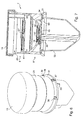
Figure 1 is an exploded perspective view of a preparation unit according to the invention; -
Figures 2 to 5 are respectively a perspective view and three views in cross-sectional elevation in different section planes of that preparation unit in which there are represented a collection module for the liquids and a filter module for those liquids which that unit comprises, the filter and collection module being disposed relative to each other in a relative angular position enabling the liquid to flow from the filter module to a first reservoir of the collection module by an evacuation aperture of the filter module. -
Figures 6 to 9 are similar views toFigures 2 to 5 but illustrating the preparation unit in another relative angular position in which the evacuation aperture which enabled the flow of the liquid from the filter module to the collection module is obturated; -
Figures 10 to 13 are similar views toFigures 2 to 5 but illustrating the preparation unit in still another relative angular position enabling the liquid to flow from the filter module to a second reservoir of the collection module by the evacuation aperture; -
Figures 14 and 15 are respectively a perspective view from above and a perspective view from below presenting a portion of the filter module body in isolation; -
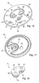
Figures 16 and 17 are two views similar toFigures 14 and 15 illustrating a disc for distributing the liquids that the collection module comprises and which cooperates with the filter module; -
Figure 18 is a perspective view presenting in isolation a seal that the filter module comprises and which cooperates with the disc for distributing the liquids; and -
Figures 19 and 20 are sectional views in elevation respectively illustrating a second and a third embodiment of the preparation unit according to the invention. - The
preparation unit 1 illustrated inFigures 1 to 13 comprises afilter module 2 and amodule 3 for collection of the liquids after they have passed through the filter module. - The filter module comprises three
filter membranes Figure 3 ) as well as acover 11 nestingly fitted around the body and obturating it. - This
cover 11 has awall 13 and anannular collar 14 with, in thecollar 14, agroove 12 which is locally formed on the inner face of that collar (represented in dashed line inFigure 1 ) to form, as will be seen below, a vent allowing air to pass. - The
body 7 has anupper portion 8 and alower portion 9 with one nested in the other. - The
portion 8 has aninlet opening 18 for the liquid whileportion 9 has an evacuation opening 19 (Figures 3 ,14 and 15 ) for that liquid. -
Portion 8 has a firstcylindrical part 20 delimiting theopening 18 and around which thecover 11 nestingly fits and a secondcylindrical part 21 of smaller diameter than the firstcylindrical part 20, these parts being connected together by a frusto-conical part 22. Thecylindrical part 21 is closed, on the opposite side to the frusto-conical part 22 by awall 23 with the exception of an opening 27 (Figure 3 ) for passage of the liquid to the following compartment. Themembranes 4 and 5 (disposed against each other) are sealed against that wall at their perimeter. - The
membranes membrane 4 being equal to 30 µm whereas the pore diameter of themembrane 5 is equal to 5 µm. - These membranes rest on a region of the
wall 23 in which are formed drainage channels for the liquid after having passed through those membranes, the channels being provided to direct the liquid to thepassage opening 27. The width of the channels (0.4 mm) is chosen so as to provide sufficient drainage of the liquid while ensuring sufficient mechanical support for themembranes - In
portion 8 there is also formed a channel 24 (Figure 3 ) open at both ends, disposed against the inner face ofpart 21 and extending beyond that part towards theopening 18. Theopening 25 of that channel is situated substantially at the level of theopening 18, and is obturated by thecover 11 when it is nestingly fitted aroundpart 20, that channel issuing, by itsopposite opening 26 to theopening 25, into the region of the filter module situated between themembrane 6, and themembranes -
Portion 9 has acylindrical part 30, a frusto-conical part 31 and atransverse wall 32. - The
cylindrical part 30 is of substantially equal diameter to the diameter of thecylindrical part 21 and has aregion 33 of reduced thickness provided to be nestingly fitted by deformation ofpart 21 and then welded against thatpart 21 to provide the integrity of the unit relative to leaks on centrifuging but also relative to risks of contamination (in particular when it is not possible to work under an extractor hood). - The frusto-
conical part 31 is connected to thepart 30 on the opposite side to that provided to be nestingly fitted intoportion 8 and tapers outwardly. - At regular intervals on that part are overprinted the
figures "1 ", "2" and "3 " respectively corresponding, as will be seen below, to the three relative angular positions which the filter and collection modules are adapted to take relative to each other. Beside each of these inscriptions is disposed a corresponding rib (36 for theFigure "1 ", 37 for theFigure "2 " and 38 for theFigure "3 ") for reading the associated position. - An
annular groove 34 is formed inpart 30 on its inner face and in the neighborhood of the junction with the frusto-conical part 31. - From the inner face of
part 30 an indexing fin 35 (Figure 15 ) also projects, which is provided for cooperating with complementary indexing means on thecollection module 3 to hold the filter module relative to the collection module in the desired position. - The
transverse wall 32 extends substantially transversely to thecylindrical part 30 while partially obturating it and joining to thepart 30 at approximately half way between its edges. This wall has a step formation at its periphery to form a bowl at the bottom of which is sealed themembrane 6 around its perimeter. - From that wall, on the opposite side to that provided for cooperating with the
membrane 6, and as illustrated inFigure 15 , project twoannular ribs - In that wall there is formed a circular opening forming the
opening 19 for evacuation of the liquid. - The
membrane 6 is formed from polyvinylidene fluoride (PVDF) and has pores of diameter equal to 0.45 µm, it rests on a region of thewall 32 in which are formed drainage channels 46 (Figure 14 ) for the liquid passing through the membrane, those channels being provided to direct the liquid to ducts that join to theevacuation opening 45. These ducts are inclined in order to ensure minimum retention of the liquid under the membrane in particular on retrieval of the lysate when centrifuging. - The
portion 8 delimits afirst compartment 40 together with themembranes portions second compartment 41 together with themembranes membrane 6 on the other side, while theportion 9 delimits, together with themembrane 6, a third compartment 42 (formed in particular by thedrainage channels 46 and by the space situated adjacent theducts 45 and the opening 19). - This filter module is thus arranged such that the introduction compartments for the liquid, formed from the
compartments evacuation compartment 42 for the liquid are on opposite sides from each other relative to the membrane 6 (that is to say on either side of the membrane 6) so as to enable the liquid to flow in a single direction for the entire length of the filtration, so making the unit compatible with the liquid flowing by centrifuging. - When the liquid is situated at the level of
compartment 41 it comes into contact with themembrane 6 over itssurface 10 so giving a large area for liquid passage also to enable its flow by centrifuging. - The
collection module 3 comprises afluid distribution disc 50, a fluid-tight seal 51, as well as afirst reservoir 52 and asecond reservoir 53 attached on the same side of thedisc 50. - The
reservoir 52 is sealed by laser welding against thedisc 50 and is provided to collect the liquid which has been filtered through the three membranes and which is not intended to be analyzed. Thereservoir 52 has a crescent-shaped cross-section (Figure 1 ) such that it thus has a recessedregion 54 in which thereservoir 53 is accommodated. From the outer surface of thereservoir 52 projects arib 55, which, as will be seen below, forms a cursor for reading the position of thefilter module 2 relative to thecollection module 3. - The
reservoir 53 has smaller capacity than thereservoir 52, and is a collector tube here of microtube type with 1.5 mL capacity. Thisreservoir 53 is provided as will be seen below for collecting microorganisms to analyze after having subjected them to lysis on themembrane 6. - The
reservoir 53 has arim 56 provided for latching cooperation with acollar 81 of thedisc 50. - This
disc 50 has awall 60 in which there are formed twoopenings opening 65 of markedly smaller diameter than that of theopenings openings ribs face 61 of thewall 60 that is situated on the opposite side to thereservoirs - The
rib 68 surrounding theaperture 65 is circular. - This disc also comprises three
ribs surface 61, each provided to form, as will be seen below, a housing for indexing the position of the collection module relative to the filter module. - The rib 69 (respectively 71) has a guide portion 72 (respectively 75) for the
indexing fin 35 that the filter module comprises, an abutment portion 73 (respectively 76) for that fin and a housing-forming cut-out 74 (respectively 77) for that fin situated between theportions - The
intermediate rib 70 has twoguide portions - This disc also comprises, projecting from the
opposite face 62 to theface 61, anannular collar 81 for latching to thereservoir 53 and anannular collar 82 for centering thereservoir 52 welded against that disc. - The
seal 51 is a seal of elastomer (of silicone in the example illustrated) of bean-shaped longitudinal section in which, in the neighborhood of each end, there is formed apassage duct wall 60 of thedisc 50 bordering the opening 63 (respectively 64). - The duct 90 (respectively 91), as illustrated in
Figure 18 , issues on the side of the seal provided to cooperate with thefilter module 2 by a first opening 95 (respectively 96) and on the opposite side by a second opening (not visible in the drawings). - In the nested position of the
seal 51 in thedisc 50, theribs - The
wall 60 of thedisc 50 is received at its periphery in theannular groove 34 of the filter module, such that the filter module is thus rotatably mounted relative to the collection module, thefin 35 of the filter module being provided to be received in one of the cut-outs - In the latched position of the
disc 50 of thecollection module 3 in thegroove 34 of thefilter module 2, theseal 51 is compressed between thewall 60 of the disc and thewall 32 of the filter module, this compression enabling the passage of the liquids from one module to the other without risk of leakage (fluid-tight connection). - The
filter module 2 is thus provided to have three distinct positions relative to thecollection module 3 with thefin 35 of the filter module being latched in the corresponding housing for each position. - Thus in the position illustrated in
Figures 2 to 5 , thefin 35 is engaged in the cut-out 74 and the collection module is disposed relative to the filter module such that the evacuation opening 19 is situated in register with theopening 95 of theduct 90 of the seal (Figure 3 ). Theevacuation compartment 42 is thus placed in communication with thereservoir 52 via theduct 90. In this way, the liquid poured into the filter module is able to pass through that module to attainreservoir 52 via themembranes membrane 6 next, and then by passing through theopening 19, theopening 95 and lastly theduct 90. - In this first position, the access to the
duct 91 and to thereservoir 53 is obturated by thewall 32 of thelower portion 9 of the filter module, so protecting that reservoir from possible contamination (Figure 4 ). - In another relative angular position of the filter module relative to the collection module illustrated in
Figures 6 to 9 , thefin 35 is in the cut-out 80 and theopenings ducts wall 32. Theannular ribs openings 95 and 96 (Figures 8 and 9 ) of the ducts while exerting a pressure against theseal 51 to ensure the fluid-tight isolation of thereservoirs - The
opening 19 of that wall is also obturated in fluid-tight manner by theportion 94 of the seal that is situated between theducts 90 and 91 (Figure 7 ), so preventing the liquid from flowing from the filter module. - Lastly, in still another relative angular position of the filter module relative to the collection module illustrated in
Figures 10 to 13 , thefin 35 is in the cut-out 77 and theopening 19 is situated in register with theopening 96 of the duct 91 (Figure 11 ). In this position theevacuation compartment 42 is placed in communication with thereservoir 53 via theduct 91 whereas the access to theduct 90 of the seal is obturated for it by thewall 32, so protecting thereservoir 52 from possible contamination (Figure 13 ). In this way, the liquid coming from thefilter module 2 is able to reach thereservoir 53 by passing through theopening 19, theopening 96 and lastly theopening 91 of the seal. - To pass from one position to the other, the operator grasps the
preparation unit 1 to rotate thefilter module 2 relative to thecollection module 3 in order to disengage thefin 35 from the cut-out in which it is disposed. Theportions ribs portions - A description will now be made of the different steps of preparing a sample to analyze from a liquid to filter which may contain, in the chosen example, not only eukaryote cells but also bacteria whose presence it is desired to detect among those cells.
- In order to detect those bacteria they should be separated from the cells contained in the liquid by way of the double stage of filtering presented by the
module 2. - In a first step, the operator grasps a preparation unit, and, if it is not already the case, turns the
filter module 2 relative to thecollection module 3 to position therib 36 associated with the position "1" on the frusto-conical portion 31 in alignment with thecursor 55 situated on thereservoir 52. - After having removed the
cover 11 in advance, the operator then pours a predetermined volume of liquid to analyze into thecompartment 40 of the filter module 2 (for example 20 ml). - The operator replaces the
cover 11 and thepreparation unit 1 is then placed in a centrifuge. - Rotating the centrifuge drives the movement of the liquid such that the predetermined volume passes through the
membranes compartment 41 of the filter module. - The large size of the pores of the
membranes compartment 41 so enabling the liquid then to pass through themembrane 6 and to flow so as to occupy thecompartment 42 and lastly, by passing through theaperture 19 and theduct 90, to reach thecollection reservoir 52 for the liquid so filtered. - The pore diameter of the membrane 5 (here 5 µm) is chosen such that only the microorganisms of greatest size, here the eukaryotes, are retained by that membrane whereas the other microorganisms, here bacteria (of size well below 5 µm), pass through it to be collected finally on the
membrane 6. - The
membrane 4, which has pores (here 30 µm) of even greater diameter than those of themembrane 5, is disposed upstream and juxtaposed against themembrane 5 to avoid any risk of clogging of themembrane 5 in case the membrane to filter were to contain a very high number of eukaryote cells to separate from the rest of the liquid. - It is to be noted in this connection that the combination 30µm/5µm for the
membranes - Such good results are obtained for pore diameters of the
membrane 4 greater than 10 µm and less than 40 µm. - The very small quantity of cells arriving on the filter membrane 6 (105 cells) thus makes it possible to significantly increase the sensitivity of such a device while reducing the background noise for the nucleic acid amplification techniques (of PRC/TMA type) in order to detect the presence of germs initially present in the filtered liquid with the greatest precision.
- The pores of the
membrane 6 are of course dimensioned (0.45 µm in this example) so as to retain the germs which it is desired to detect. - During the filling of the
reservoir 52, the reduction in the volume of air in that reservoir does not lead to any pressurization phenomenon in that reservoir due to the presence of theopening 65 forming a vent enabling thereservoir 52 and thus thecompartment 42 to be kept at atmospheric pressure, which thus prevents any risk of themembrane 6 doming during the filtration of the liquid. - Similarly, the vent 12 (
Figure 1 ) formed in thecover 11 ensures thecompartments membrane 6 doming, not by pressurization in thecompartment 42 but by depressurization in thecompartments - Once this operation has been accomplished, the operator stops the centrifuge and grasps the preparation unit to perform a movement of relative rotation of the filter module relative to the collection module so as to position the
rib 37 situated beside theFigure "2 " on the frusto-conical part 31 of the filter module in alignment with the cursor 55 (Figure 6 ). - In this
position 2, theducts transverse wall 32 and theopening 19 is obturated by thesolid portion 94 of the seal. In this manner, no flow either of liquid or of air is possible between thecompartment 42 of the filter module and thereservoirs - There is thus no risk of contamination of the
reservoir 53 by the liquid contained in the reservoir 52 (by evaporation/condensation). - The operator can then remote the
cover 11 to pour into the channel 25 a predetermined volume of a lysing agent (300 µL for example) which, in flowing through that channel, will reachcompartment 41 to cover theupper surface 10 of themembrane 6. After having deposited the lysing agent, the operator then replaces thecover 11. - As the
vent 65 of thedisc 50 and thevent 12 of thecover 11 have enabled thecompartments membrane 6 remains flat which enables the lysing agent to be deposited homogenously and evenly over the whole of the membrane (and not solely at its perimeter which would be the case if the membrane had become domed). - As no liquid flow is possible towards the reservoirs of the collection module, the lysing agent is deliberately kept in contact with the membrane for a predetermined time in order for the lysis of the germs to be as effective as possible.
- After having kept the lysing agent in contact with the membrane for that predetermined time (depending on the lysing agent) at a predetermined temperature (for example 60°) in order to increase the effectiveness of the agent, the operator again turns the filter module relative to the collection module to position the
rib 38 situated beside thefigure "3 " on the frusto-conical part 31 of the filter module in alignment with the cursor 55 (Figure 10 ). - The preparation unit is then again placed in the centrifuge to make the lysate (containing the biological material of the bacteria) pass through the
equipment 6, that biological material, after having undergone the lysis, being of sufficiently reduced size to pass through the pores of that membrane and thus to be collected in thereservoir 53. - The operator can then remove the preparation unit from the centrifuge and unlatch the
reservoir 53 from thedisc 50 to perform an analysis of the lysate collected in that reservoir. - It will be noted that the microorganisms to detect are not necessarily bacteria but may in particular be viruses, yeasts (of sufficiently small size not to be retained by the
membranes 4 and 5) or moulds. It may be that the liquid to analyze does not contain eukaryote cells but other types of microorganisms (to separate from the germs to detect) such as yeast or filamentous fungi. - Another embodiment of the preparation unit is represented in
Figure 19 . - Generally, the same reference numbers are used for similar elements, but increased by 100 for each embodiment.
- The
preparation unit 101 ofFigure 19 is similar to theunit 1 apart from thereservoir 53 being eliminated in this embodiment, theterminal formation 181 of the disc 150 being in this case provided to be connected for example to ahose 157, as illustrated inFigure 19 , leading to a remote reservoir for example. - In still another embodiment not illustrated, the
reservoir 152 is similarly replaced. - Another embodiment of the preparation unit is represented in
Figure 20 . - The
preparation unit 201 ofFigure 20 comprises afilter module 202 and acollection module 203, the filter module being provided with amembrane 206 with themodules - Like the
units Figure 20 in which theopening 296 of the seal is placed in register with anadditional opening 298 formed in a wall of thecollection module 203. This opening is obturated by a heat-sealed film (not illustrated) that the operator can detach such that thereservoir 253 is made accessible in order to be able to directly take off therefrom the liquid it contains using apipette 99 rather than unlatching thatreservoir 253 from the rest of thecollection module 203. - In another embodiment, not illustrated, the
cover 11 is replaced, in particular when it is impossible to work under an extractor hood or in a confined space protected from contaminations, by a cover provided to be welded to the body of the filter module in order to reduce the risk of contamination, that cover then having, in that case, a first terminal formation (of female Luer type for example) to connect a valve by which the volume of liquid to filter is introduced, a second terminal formation, also of female Luer type, to connect a microbiological filter comprising a membrane that forms a barrier to microorganisms (porosity 0.22 µm) but permeable to the air in order therefore to enable sterile venting of thecompartment 40, as well as a third female Luer terminal formation to connect a syringe provided with a male Luer terminal formation, that third terminal formation issuing in theaccess channel 24 and being obturated by a plug when the syringe is not connected to that terminal formation. - In another embodiment, not illustrated, the preparation unit lacks the
membranes filter membrane 6 and/or thatmembrane 6 is not of PVDF but of polyestersulfone (PES) for example. - It is also to be noted that the preparation unit according to the invention may also be used for any other filtration method instead of the one described above for example for a filtration method in which the lysis is not carried out by a liquid chemical agent but by emitting ultrasound towards the
membrane 6 or by micro-wave heating of that membrane and then by retrieving the biological material that underwent the lysis on the membrane by passing a collection liquid into the preparation unit which is collected in thereservoir 53. - More generally, the preparation unit may also be used for any other filtration method requiring liquids to be collected in at least two different receptacles.
- The present invention is not limited to the embodiments described and represented but encompasses any variant form thereof.
Claims (28)
- A unit for preparing a sample for the microbiological analysis of a predetermined volume of liquid that may contain microorganisms comprising a filter membrane filter module (2 ; 102 ; 202) and a collection module (3 ; 103 ; 203) for each liquid coming from said filter module (2 ; 102 ; 202), with said filter module (2 ; 102; 202) comprising an inlet compartment (40, 41 ; 140, 141; 240, 241) for inletting said predetermined volume by an inlet opening (18; 118; 218) of said filter module (2 ; 102 ; 202), said inlet compartment (40, 41 ; 140, 141 ; 240, 241) being adapted to contain the whole of said predetermined volume, as well as an evacuation compartment (42 ; 142 ; 242) for evacuating said predetermined volume by an evacuation opening (19 ; 219) of said filter module (2 ; 102 ; 202) to said collection module (3 ; 103 ; 203), said evacuation compartment (42 ; 142 ; 242) being separated from said inlet compartment (40, 41 ; 140, 141 ; 240, 241) by said membrane (6 ; 106 ; 206), the filter (2 ; 102 ; 202) and collection (3 ; 103 ; 203) modules being rotatably mounted relative to each other, and having, relative to each other, a first relative predetermined position, in which said evacuation opening (19 ; 219) of said filter module (2 ; 102 ; 202) is in register with a first opening (95) of said collection module (3 ; 103 ; 203) and a second relative predetermined position different from said first position, in which said evacuation opening (19 ; 219) of said filter module (2 ; 102 ; 202) is in register with a second opening (96 ; 196 ; 296) of said collection module (3 ; 103 ; 203); characterized in that said inlet (40, 41 ; 140, 141 ; 240, 241) and evacuation (42 ; 142 ; 242) compartments are on opposite sides from each other relative to said filter membrane (6 ; 106 ; 206) with said inlet compartment (40, 41 ; 140, 141 ; 240, 241) being arranged such that, when said predetermined volume is in said inlet compartment (40, 41 ; 140, 141 ; 240, 241), the liquid is in contact with the filter membrane (6 ; 106 ; 206) over at least the majority of its surface (10 ; 110 ; 210).
- A unit according to claim 1, characterized in that , in said first predetermined position, said second opening (96 ; 196 ; 296) is obturated and in that, in said second predetermined position, said first opening (95) is obturated.
- A unit according to any one of claims 1 or 2, characterized in that said filter (2 ; 102 ; 202) and collection (3 ; 103 ; 203) modules also have another predetermined position relative to each other, termed obturating position, different from the first and second positions, in which said evacuation opening (19 ; 219) is obturated.
- A unit according to claim 3, characterized in that in said obturating position, said first (95) and second (96 ; 196 ; 296) openings are also obturated.
- A unit according to any one of claims 1 to 4, characterized in that said filter (202) and collection (203) modules also have another predetermined position relative to each other, termed take-off position, different from the first and second positions, in which said second opening (296) is in register with a take-off opening (298) that said unit comprises.
- A unit according to any one of claims 1 to 5, characterized in that said filter module (2 ; 102) comprises a body (7 ; 107 ; 207) within which is fixed said filter membrane (6 ; 106 ; 206) as well as a separation membrane (5 ; 105 ; 205) that is situated between said inlet opening (18 ; 118 ; 218) and said filter membrane (6 ; 106 ; 206), said separation membrane (5 ; 105 ; 205) having a pore diameter greater than the pore diameter of said filter membrane (6 ; 106 ; 206).
- A unit according to claim 6, characterized in that said separation membrane (5 ; 105) is fixed to a first portion (8 ; 108) of said body (7 ; 107) and said filter membrane (6 ; 106) is fixed to a second portion (9 ; 109) of said body (7 ; 107), with said first (8 ; 108) and second (9 ; 109) portions being adapted to be nested one inside the other and welded together.
- A unit according to any one of claims 6 or 7, characterized in that said filter module (2 ; 102) comprises another membrane (4 ; 104), juxtaposed against said separation membrane (5 ; 105), on the opposite side of the separation membrane (5 ; 105) to the filter membrane (6 ; 106), said other membrane (4 ; 104) having a greater pore diameter than the pore diameter of said separation membrane (5 ; 105).
- A unit according to any one of claims 6 to 8, characterized in that the pore diameter of said separation membrane (5 ; 105) is greater than 1 µm.
- A unit according to any one of claims 6 to 9, characterized in that the pore diameter of said filter membrane (6 ; 106 ; 206) is less than 1 µm.
- A unit according to any one of claims 6 to 10, characterized in that said filter module (2) comprises another opening (25) formed in said body (7) and giving access to a compartment (41) of said body (7) situated between said separation (5) and filter (6) membranes.
- A unit according to claim 11, characterized in that said opening (25) is situated at the end of a channel (24) formed in said body (7).
- A unit according to claim 12, characterized in that said opening (25) of said channel (24) is substantially situated at the same level as the inlet opening (18) of the liquid that may contain microorganisms.
- A unit according to any one of claims 1 to 13, characterized in that said collection module (3) comprises a disc (50) of which the perimeter is adapted to be received in an annular groove (34) that said filter module (2) comprises.
- A unit according to any one of claims 1 to 14, characterized in that said filter module (2) comprises indexing means (35) and said collection module (3) comprises complementary indexing means (69, 70, 71) for each predetermined position of the filter module (2) relative to the collection module (3).
- A unit according to claim 15, characterized in that said indexing means comprise a fin (35) and in that said complementary indexing means comprise ribs (69, 70, 71) each having a cut-out (74, 77, 80) adapted to receive said fin (35).
- A unit according to any one of claims 1 to 16, characterized in that said first opening (95) of the collection module (3) issues to a reservoir (52) that said collection module (3) comprises.
- A unit according to claim 17, characterized in that the collection module (3) comprises a vent (65) adapted allow air to pass into said reservoir (52).
- A unit according to any one of claims 17 or 18, characterized in that said reservoir (52) has a crescent-shaped cross-section.
- A unit according to any one of claims 1 to 19, characterized in that said second opening (96) of the collection module (3) issues to a reservoir (53) that said collection module (3) comprises.
- A unit according to claim 20, characterized in that said reservoir (53) has latching means (56) adapted to cooperate with complementary latching means (81) that said collection module (3) comprises.
- A unit according to any one of claims 1 to 21, characterized in that said collection module (3) comprises a seal (51) in which are formed two ducts (90, 91), each respectively issuing, on the same side as the filter module (2), by said first opening (95) and by said second (96) opening.
- A unit according to claim 22, characterized in that said seal (51) has a bean-shaped cross-section.
- A unit according to any one of claims 1 to 23, characterized in that said filter module (2) comprises a vent (12) adapted to allow air to pass into said inlet compartment (40, 41).
- A method of preparing a sample for the microbiological analysis of a predetermined volume of liquid that may contain microorganisms, characterized in that it comprises:- the step of obtaining a preparation unit (1 ; 101 ; 201) according to any one of claims 1 to 24;- the step of disposing the filter module (2 ; 102 ; 202) and collection module (3 ; 103 ; 203) of that unit (1) relative to each other in said first predetermined position;- the step of passing said predetermined volume of liquid that may contain microorganisms from the filter module (2 ; 102 ; 202) to attain the collection module (3 ; 103 ; 203) through said evacuation opening (19 ; 219) of the filter module (2 ; 102 ; 202) and through said first opening (95) of the collection module (3 ; 103 ; 203);- the step of disposing the filter module (2 ; 102 ; 202) and collection module (3 ; 103 ; 203) relative to each other in said second predetermined position; and- the step of passing a predetermined volume of another liquid from the filter module (2 ; 102 ; 202) to attain the collection module (3 ; 103 ; 203) through said evacuation opening (19 ; 219) of the filter module (2 ; 102 ; 202) and through said second opening (96 ; 196 ; 296) of the collection module (3 ; 103 ; 203).
- A method according to claim 25, characterized in that said steps of passing said predetermined volumes from the filter module (2 ; 102 ; 202) to attain the collection module (3 ; 103 ; 203) are implemented by centrifuging.
- A method according to any one of claims 25 or 26, characterized in that it comprises, prior to said step of passing said predetermined volume of said other liquid through said evacuation opening (19 ; 219) of the filter module (2 ; 102 ; 202) and through said second opening (96 ; 196 ; 296) of the collection module (3 ; 103 ; 203), the step of selecting as other liquid, a liquid adapted to cause the lysis of the microorganisms retained on said filter membrane (6 ; 106 ; 206), the step of depositing on said filter membrane (6 ; 106 ; 206) said predetermined volume of said other liquid, and then the step of leaving said other liquid to act on said microorganisms for a predetermined time.
- A method according to claim 27, characterized in that it comprises, subsequent to the step of passing said predetermined volume of said other liquid through said evacuation opening (19 ; 219) of the filter module (2 ; 102 ; 202) and through said second opening (96) of the collection module (3 ; 103 ; 203), the step of retrieving said predetermined volume of said other liquid for analysis.
Applications Claiming Priority (1)
| Application Number | Priority Date | Filing Date | Title |
|---|---|---|---|
| FR0854844A FR2934049B1 (en) | 2008-07-16 | 2008-07-16 | UNIT AND METHOD FOR PREPARING A SAMPLE FOR THE MICROBIOLOGICAL ANALYSIS OF A LIQUID |
Publications (3)
| Publication Number | Publication Date |
|---|---|
| EP2187221A2 true EP2187221A2 (en) | 2010-05-19 |
| EP2187221A3 EP2187221A3 (en) | 2014-02-05 |
| EP2187221B1 EP2187221B1 (en) | 2017-08-23 |
Family
ID=40637064
Family Applications (1)
| Application Number | Title | Priority Date | Filing Date |
|---|---|---|---|
| EP09290531.4A Active EP2187221B1 (en) | 2008-07-16 | 2009-07-02 | A unit and method for preparing a sample for the microbiological analysis of a liquid |
Country Status (7)
| Country | Link |
|---|---|
| US (2) | US8133457B2 (en) |
| EP (1) | EP2187221B1 (en) |
| JP (1) | JP5193136B2 (en) |
| CN (1) | CN101629140B (en) |
| ES (1) | ES2647071T3 (en) |
| FR (1) | FR2934049B1 (en) |
| SG (1) | SG158800A1 (en) |
Cited By (1)
| Publication number | Priority date | Publication date | Assignee | Title |
|---|---|---|---|---|
| WO2014111064A1 (en) * | 2013-01-18 | 2014-07-24 | Wolf & Danniel S.R.O. | Method of manipulation with samples of biological material and a device for such manipulation |
Families Citing this family (35)
| Publication number | Priority date | Publication date | Assignee | Title |
|---|---|---|---|---|
| FR2902799B1 (en) | 2006-06-27 | 2012-10-26 | Millipore Corp | METHOD AND UNIT FOR PREPARING A SAMPLE FOR THE MICROBIOLOGICAL ANALYSIS OF A LIQUID |
| US8569464B2 (en) | 2006-12-21 | 2013-10-29 | Emd Millipore Corporation | Purification of proteins |
| US8362217B2 (en) | 2006-12-21 | 2013-01-29 | Emd Millipore Corporation | Purification of proteins |
| WO2008079280A1 (en) | 2006-12-21 | 2008-07-03 | Millipore Corporation | Purification of proteins |
| FR2928632B1 (en) * | 2008-03-11 | 2012-06-01 | Imagene | CONTAINER FOR RECEIVING AND RETAINING BIOLOGICAL MATERIAL, IN PARTICULAR DNA |
| FR2934049B1 (en) * | 2008-07-16 | 2010-10-15 | Millipore Corp | UNIT AND METHOD FOR PREPARING A SAMPLE FOR THE MICROBIOLOGICAL ANALYSIS OF A LIQUID |
| CN105037535A (en) | 2008-12-16 | 2015-11-11 | Emd密理博公司 | Stirred tank reactor and method |
| CN102301218B (en) * | 2009-01-29 | 2014-05-14 | 株式会社日立高新技术 | Device for pretreating sample and mass spectrometer equipped with same |
| TWI464151B (en) | 2009-07-06 | 2014-12-11 | Alcon Inc | Uv/visible light absorbers for ophthalmic lens materials |
| KR101726707B1 (en) | 2010-05-17 | 2017-04-13 | 이엠디 밀리포어 코포레이션 | Stimulus responsive polymers for the purification of biomolecules |
| US8616443B2 (en) | 2010-05-28 | 2013-12-31 | Securitymetrics, Inc. | Systems and methods employing delimiter searches to identify sensitive information in data |
| ES2587054T3 (en) * | 2011-02-17 | 2016-10-20 | Nestec S.A. | Apparatus and method for isolating leukocytes and tumor cells by filtration |
| EP2726843B1 (en) | 2011-06-30 | 2016-03-02 | 3M Innovative Properties Company | Systems and methods for detecting an analyte of interest in a sample using filters and microstructured surfaces |
| US9488563B2 (en) | 2011-06-30 | 2016-11-08 | 3M Innovative Properties Company | Systems and methods for detecting an analyte of interest in a sample using microstructured surfaces |
| WO2013090825A1 (en) | 2011-12-15 | 2013-06-20 | Pureflora, Inc. | Device for the collection, refinement, and administration of gastrointestinal microflora |
| CN104884933B (en) * | 2012-10-18 | 2019-03-01 | 伊诺瓦普瑞普有限公司 | Liquid is classified and is concentrated to the biomone of liquid |
| KR20160018581A (en) * | 2013-05-29 | 2016-02-17 | 프로브타가렌 에이비 | Fluid-tightly sealable sampling device |
| GB201316347D0 (en) * | 2013-09-13 | 2013-10-30 | Cancer Rec Tech Ltd | Biological fluid filtration assembly |
| PL3086816T3 (en) * | 2013-12-23 | 2018-04-30 | Merck Patent Gmbh | Sample preparation unit and sample preparation device |
| EP3129733B1 (en) * | 2014-04-07 | 2021-08-18 | Merck Patent GmbH | Apparatus and method for removing moisture from a surface in a container |
| JP6444615B2 (en) * | 2014-05-20 | 2018-12-26 | 株式会社ビケンバイオミクス | Separation container and virus concentration / purification method |
| CN104498348A (en) * | 2014-12-19 | 2015-04-08 | 武汉友芝友医疗科技有限公司 | Filter used for separating specific cells |
| JP2018088831A (en) * | 2015-04-03 | 2018-06-14 | 株式会社カネカ | Cell separation devices and cell separation systems |
| CN105784454B (en) * | 2016-05-04 | 2017-04-19 | 中国水利水电科学研究院 | Combined water sample filter |
| US10417283B2 (en) | 2016-07-14 | 2019-09-17 | Securitymetrics, Inc. | Identification of potentially sensitive information in data strings |
| WO2018075250A1 (en) * | 2016-10-17 | 2018-04-26 | Emd Millipore Corporation | Device suitable for vacuum assisted filtration |
| KR20190052145A (en) * | 2016-11-02 | 2019-05-15 | 이엠디 밀리포어 코포레이션 | A container for separating microcarriers from a cell culture fluid |
| CN111855333B (en) * | 2019-04-24 | 2023-10-03 | 青岛言鼎生物医疗科技有限公司 | Device and method for integrating enrichment and dye-printing absorption and dyeing of nucleated cells in body fluid |
| GB201907537D0 (en) | 2019-05-29 | 2019-07-10 | Waterford Institute Of Tech | Modular sample processing device |
| JP7359632B2 (en) * | 2019-10-11 | 2023-10-11 | 株式会社日立ハイテク | Bacterial flora collection device and bacterial flora collection method |
| CN111569959B (en) * | 2020-04-30 | 2021-09-17 | 上海邦先医疗科技有限公司 | Micro-fluidic chip for quantitatively detecting bacteria in biological sample and use method |
| CN112495022A (en) * | 2020-11-23 | 2021-03-16 | 北京怡盛原环保科技有限公司 | Novel water purifying device and using method thereof |
| JP7446255B2 (en) | 2021-03-24 | 2024-03-08 | 株式会社日立ハイテク | Centrifugal filtration cartridge and microbial testing method |
| CN113789252A (en) * | 2021-08-31 | 2021-12-14 | 广州市顺元医疗器械有限公司 | Microbial filtration device, full-automatic little biological collection detection device |
| US20240151614A1 (en) * | 2022-01-28 | 2024-05-09 | Shenzhen Huixin Life Technologies Co., Ltd | Isolation device and isolation method |
Citations (1)
| Publication number | Priority date | Publication date | Assignee | Title |
|---|---|---|---|---|
| US6374684B1 (en) | 2000-08-25 | 2002-04-23 | Cepheid | Fluid control and processing system |
Family Cites Families (27)
| Publication number | Priority date | Publication date | Assignee | Title |
|---|---|---|---|---|
| US2923669A (en) * | 1954-11-22 | 1960-02-02 | Millipore Filter Corp | Method of bacterial analysis |
| US3211645A (en) * | 1962-07-17 | 1965-10-12 | Technicon Instr | Method and apparatus for filtering sanguineous liquid streams |
| US4215198A (en) * | 1978-09-15 | 1980-07-29 | Gordon Maurice R | Sterility testing unit |
| US4317726A (en) * | 1981-02-12 | 1982-03-02 | The United States Of America As Represented By The Secretary Of The Army | Microbial filter assembly |
| DE3145320C2 (en) * | 1981-11-14 | 1987-03-19 | Biotest-Serum-Institut Gmbh, 6000 Frankfurt | Microfiltration device for filtration of clots and microaggregates from blood |
| US4528933A (en) * | 1983-05-11 | 1985-07-16 | Robert Allen | Container with indicating closure |
| WO1989001966A1 (en) * | 1987-08-27 | 1989-03-09 | Polyfiltronics Limited | Filter units for biological sample preparation |
| US5139031A (en) * | 1989-09-18 | 1992-08-18 | La Mina Ltd. | Method and device for cytology and microbiological testing |
| JPH02255074A (en) * | 1989-03-29 | 1990-10-15 | Shimadzu Corp | Apparatus for collecting lysed bacterial component, method for collecting lysed bacterial component and examination of bacteria |
| US5116754A (en) * | 1990-10-04 | 1992-05-26 | Fraser Ann D E | Separation of bacteria from organic matter |
| US5342581A (en) * | 1993-04-19 | 1994-08-30 | Sanadi Ashok R | Apparatus for preventing cross-contamination of multi-well test plates |
| GB9503109D0 (en) | 1995-02-17 | 1995-04-05 | Hampshire Advisory Tech Serv | Diagnostic test tube and kits |
| DK1034039T3 (en) * | 1997-11-28 | 2003-06-02 | Provalis Diagnostics Ltd | Apparatus and system for conducting an analysis |
| JPH11201953A (en) * | 1998-01-14 | 1999-07-30 | Toyota Central Res & Dev Lab Inc | Cartridge for solid-phase extraction apparatus |
| JP2001305130A (en) * | 2000-04-21 | 2001-10-31 | Fuji Photo Film Co Ltd | Multi-specimen blood filtering device |
| US6688487B2 (en) * | 2001-04-13 | 2004-02-10 | The Coca-Cola Company | Locking cup and lid with negative draft sealing surfaces |
| JP3907508B2 (en) * | 2001-07-30 | 2007-04-18 | 松下エコシステムズ株式会社 | Microorganism collection chip, microorganism collection kit, microorganism measurement method, and microorganism measurement apparatus |
| FR2829500B1 (en) * | 2001-09-13 | 2003-12-12 | Hemosystem | PROCESS FOR THE CONCENTRATION AND DETECTION OF PATHOGENIC SPROUTS FROM BLOOD PRODUCTS AND / OR DERIVATIVES THEREOF AND DEVICE FOR CARRYING OUT SAID METHOD |
| EP1511836A1 (en) * | 2002-06-07 | 2005-03-09 | Millipore Corporation | Kit and process for microbiological for on-site examination of a liquid sample |
| US6949625B2 (en) * | 2003-05-12 | 2005-09-27 | Khorionyx | Injectable implant of insoluble globin |
| US8105849B2 (en) * | 2004-02-27 | 2012-01-31 | Board Of Regents, The University Of Texas System | Integration of fluids and reagents into self-contained cartridges containing sensor elements |
| JP5103003B2 (en) * | 2006-11-09 | 2012-12-19 | シスメックス株式会社 | Cell processing equipment |
| FR2902799B1 (en) * | 2006-06-27 | 2012-10-26 | Millipore Corp | METHOD AND UNIT FOR PREPARING A SAMPLE FOR THE MICROBIOLOGICAL ANALYSIS OF A LIQUID |
| CN101173209A (en) * | 2006-11-02 | 2008-05-07 | 杭州晶格科学仪器有限公司 | Diaphragm type liquid basal cell gathering system and method thereof |
| WO2008061317A1 (en) * | 2006-11-24 | 2008-05-29 | Xtralis Technologies Ltd | Filter arrangement |
| CN100577267C (en) * | 2007-03-30 | 2010-01-06 | 西安建筑科技大学 | Control device for fully-automatic constant-flow super-filtering water treatment |
| FR2934049B1 (en) | 2008-07-16 | 2010-10-15 | Millipore Corp | UNIT AND METHOD FOR PREPARING A SAMPLE FOR THE MICROBIOLOGICAL ANALYSIS OF A LIQUID |
-
2008
- 2008-07-16 FR FR0854844A patent/FR2934049B1/en active Active
-
2009
- 2009-07-02 ES ES09290531.4T patent/ES2647071T3/en active Active
- 2009-07-02 EP EP09290531.4A patent/EP2187221B1/en active Active
- 2009-07-03 SG SG200904524-6A patent/SG158800A1/en unknown
- 2009-07-03 JP JP2009158440A patent/JP5193136B2/en active Active
- 2009-07-09 US US12/459,879 patent/US8133457B2/en active Active
- 2009-07-15 CN CN2009101399287A patent/CN101629140B/en active Active
-
2011
- 2011-04-04 US US13/079,268 patent/US8241591B2/en active Active
Patent Citations (1)
| Publication number | Priority date | Publication date | Assignee | Title |
|---|---|---|---|---|
| US6374684B1 (en) | 2000-08-25 | 2002-04-23 | Cepheid | Fluid control and processing system |
Cited By (1)
| Publication number | Priority date | Publication date | Assignee | Title |
|---|---|---|---|---|
| WO2014111064A1 (en) * | 2013-01-18 | 2014-07-24 | Wolf & Danniel S.R.O. | Method of manipulation with samples of biological material and a device for such manipulation |
Also Published As
| Publication number | Publication date |
|---|---|
| FR2934049A1 (en) | 2010-01-22 |
| ES2647071T3 (en) | 2017-12-19 |
| US8241591B2 (en) | 2012-08-14 |
| CN101629140B (en) | 2013-08-21 |
| US20100012589A1 (en) | 2010-01-21 |
| EP2187221B1 (en) | 2017-08-23 |
| EP2187221A3 (en) | 2014-02-05 |
| US8133457B2 (en) | 2012-03-13 |
| JP5193136B2 (en) | 2013-05-08 |
| CN101629140A (en) | 2010-01-20 |
| FR2934049B1 (en) | 2010-10-15 |
| JP2010025931A (en) | 2010-02-04 |
| SG158800A1 (en) | 2010-02-26 |
| US20110174735A1 (en) | 2011-07-21 |
Similar Documents
| Publication | Publication Date | Title |
|---|---|---|
| EP2187221B1 (en) | A unit and method for preparing a sample for the microbiological analysis of a liquid | |
| US11918192B2 (en) | Medical apparatus and method for collecting biological samples | |
| JP4117191B2 (en) | Multiwell filtration device | |
| US5603899A (en) | Multiple column chromatography assembly | |
| CN101600501B (en) | Reactor for performing biochemical processes | |
| EP2882512B1 (en) | Method and separation device for separating a filtrate from a sample fluid | |
| EP0339769A1 (en) | Multi-well filter strip and composite assemblies | |
| EP1985693B1 (en) | Microbiological analysis assembly and method | |
| JP6612259B2 (en) | Fluid transfer device and method for transferring fluid aseptically | |
| JP4245274B2 (en) | Test specimen preparation device and preparation method | |
| WO1992016294A1 (en) | A device and a method for separating liquid samples | |
| US8062884B2 (en) | Handling kit for analyzing a liquid sample by nucleic acid amplification | |
| CN109529444A (en) | The filtering technique and filter of haemocyte in a kind of removal blood sample | |
| WO2017143306A1 (en) | Container for a filtration assembly |
Legal Events
| Date | Code | Title | Description |
|---|---|---|---|
| PUAI | Public reference made under article 153(3) epc to a published international application that has entered the european phase |
Free format text: ORIGINAL CODE: 0009012 |
|
| AK | Designated contracting states |
Kind code of ref document: A2 Designated state(s): AT BE BG CH CY CZ DE DK EE ES FI FR GB GR HR HU IE IS IT LI LT LU LV MC MK MT NL NO PL PT RO SE SI SK SM TR |
|
| AX | Request for extension of the european patent |
Extension state: AL BA RS |
|
| RAP1 | Party data changed (applicant data changed or rights of an application transferred) |
Owner name: EMD MILLIPORE CORPORATION |
|
| REG | Reference to a national code |
Ref country code: DE Ref legal event code: R079 Ref document number: 602009047874 Country of ref document: DE Free format text: PREVIOUS MAIN CLASS: G01N0035100000 Ipc: G01N0001400000 |
|
| PUAL | Search report despatched |
Free format text: ORIGINAL CODE: 0009013 |
|
| AK | Designated contracting states |
Kind code of ref document: A3 Designated state(s): AT BE BG CH CY CZ DE DK EE ES FI FR GB GR HR HU IE IS IT LI LT LU LV MC MK MT NL NO PL PT RO SE SI SK SM TR |
|
| AX | Request for extension of the european patent |
Extension state: AL BA RS |
|
| RIC1 | Information provided on ipc code assigned before grant |
Ipc: G01N 1/28 20060101ALI20140102BHEP Ipc: B01L 3/00 20060101ALI20140102BHEP Ipc: G01N 1/40 20060101AFI20140102BHEP Ipc: C12M 1/12 20060101ALI20140102BHEP Ipc: G01N 35/10 20060101ALI20140102BHEP |
|
| 17P | Request for examination filed |
Effective date: 20140430 |
|
| RBV | Designated contracting states (corrected) |
Designated state(s): AT BE BG CH CY CZ DE DK EE ES FI FR GB GR HR HU IE IS IT LI LT LU LV MC MK MT NL NO PL PT RO SE SI SK SM TR |
|
| 17Q | First examination report despatched |
Effective date: 20150812 |
|
| GRAP | Despatch of communication of intention to grant a patent |
Free format text: ORIGINAL CODE: EPIDOSNIGR1 |
|
| STAA | Information on the status of an ep patent application or granted ep patent |
Free format text: STATUS: GRANT OF PATENT IS INTENDED |
|
| INTG | Intention to grant announced |
Effective date: 20170210 |
|
| GRAS | Grant fee paid |
Free format text: ORIGINAL CODE: EPIDOSNIGR3 |
|
| GRAA | (expected) grant |
Free format text: ORIGINAL CODE: 0009210 |
|
| STAA | Information on the status of an ep patent application or granted ep patent |
Free format text: STATUS: THE PATENT HAS BEEN GRANTED |
|
| AK | Designated contracting states |
Kind code of ref document: B1 Designated state(s): AT BE BG CH CY CZ DE DK EE ES FI FR GB GR HR HU IE IS IT LI LT LU LV MC MK MT NL NO PL PT RO SE SI SK SM TR |
|
| REG | Reference to a national code |
Ref country code: GB Ref legal event code: FG4D |
|
| REG | Reference to a national code |
Ref country code: CH Ref legal event code: EP |
|
| REG | Reference to a national code |
Ref country code: AT Ref legal event code: REF Ref document number: 921862 Country of ref document: AT Kind code of ref document: T Effective date: 20170915 |
|
| REG | Reference to a national code |
Ref country code: IE Ref legal event code: FG4D |
|
| REG | Reference to a national code |
Ref country code: DE Ref legal event code: R096 Ref document number: 602009047874 Country of ref document: DE |
|
| REG | Reference to a national code |
Ref country code: CH Ref legal event code: NV Representative=s name: KIRKER AND CIE S.A., CH |
|
| REG | Reference to a national code |
Ref country code: NL Ref legal event code: FP |
|
| REG | Reference to a national code |
Ref country code: ES Ref legal event code: FG2A Ref document number: 2647071 Country of ref document: ES Kind code of ref document: T3 Effective date: 20171219 |
|
| REG | Reference to a national code |
Ref country code: LT Ref legal event code: MG4D |
|
| REG | Reference to a national code |
Ref country code: AT Ref legal event code: MK05 Ref document number: 921862 Country of ref document: AT Kind code of ref document: T Effective date: 20170823 |
|
| PG25 | Lapsed in a contracting state [announced via postgrant information from national office to epo] |
Ref country code: LT Free format text: LAPSE BECAUSE OF FAILURE TO SUBMIT A TRANSLATION OF THE DESCRIPTION OR TO PAY THE FEE WITHIN THE PRESCRIBED TIME-LIMIT Effective date: 20170823 Ref country code: AT Free format text: LAPSE BECAUSE OF FAILURE TO SUBMIT A TRANSLATION OF THE DESCRIPTION OR TO PAY THE FEE WITHIN THE PRESCRIBED TIME-LIMIT Effective date: 20170823 Ref country code: SE Free format text: LAPSE BECAUSE OF FAILURE TO SUBMIT A TRANSLATION OF THE DESCRIPTION OR TO PAY THE FEE WITHIN THE PRESCRIBED TIME-LIMIT Effective date: 20170823 Ref country code: FI Free format text: LAPSE BECAUSE OF FAILURE TO SUBMIT A TRANSLATION OF THE DESCRIPTION OR TO PAY THE FEE WITHIN THE PRESCRIBED TIME-LIMIT Effective date: 20170823 Ref country code: NO Free format text: LAPSE BECAUSE OF FAILURE TO SUBMIT A TRANSLATION OF THE DESCRIPTION OR TO PAY THE FEE WITHIN THE PRESCRIBED TIME-LIMIT Effective date: 20171123 Ref country code: HR Free format text: LAPSE BECAUSE OF FAILURE TO SUBMIT A TRANSLATION OF THE DESCRIPTION OR TO PAY THE FEE WITHIN THE PRESCRIBED TIME-LIMIT Effective date: 20170823 |
|
| PG25 | Lapsed in a contracting state [announced via postgrant information from national office to epo] |
Ref country code: PL Free format text: LAPSE BECAUSE OF FAILURE TO SUBMIT A TRANSLATION OF THE DESCRIPTION OR TO PAY THE FEE WITHIN THE PRESCRIBED TIME-LIMIT Effective date: 20170823 Ref country code: LV Free format text: LAPSE BECAUSE OF FAILURE TO SUBMIT A TRANSLATION OF THE DESCRIPTION OR TO PAY THE FEE WITHIN THE PRESCRIBED TIME-LIMIT Effective date: 20170823 Ref country code: GR Free format text: LAPSE BECAUSE OF FAILURE TO SUBMIT A TRANSLATION OF THE DESCRIPTION OR TO PAY THE FEE WITHIN THE PRESCRIBED TIME-LIMIT Effective date: 20171124 Ref country code: IS Free format text: LAPSE BECAUSE OF FAILURE TO SUBMIT A TRANSLATION OF THE DESCRIPTION OR TO PAY THE FEE WITHIN THE PRESCRIBED TIME-LIMIT Effective date: 20171223 Ref country code: BG Free format text: LAPSE BECAUSE OF FAILURE TO SUBMIT A TRANSLATION OF THE DESCRIPTION OR TO PAY THE FEE WITHIN THE PRESCRIBED TIME-LIMIT Effective date: 20171123 |
|
| PG25 | Lapsed in a contracting state [announced via postgrant information from national office to epo] |
Ref country code: DK Free format text: LAPSE BECAUSE OF FAILURE TO SUBMIT A TRANSLATION OF THE DESCRIPTION OR TO PAY THE FEE WITHIN THE PRESCRIBED TIME-LIMIT Effective date: 20170823 Ref country code: CZ Free format text: LAPSE BECAUSE OF FAILURE TO SUBMIT A TRANSLATION OF THE DESCRIPTION OR TO PAY THE FEE WITHIN THE PRESCRIBED TIME-LIMIT Effective date: 20170823 Ref country code: RO Free format text: LAPSE BECAUSE OF FAILURE TO SUBMIT A TRANSLATION OF THE DESCRIPTION OR TO PAY THE FEE WITHIN THE PRESCRIBED TIME-LIMIT Effective date: 20170823 |
|
| REG | Reference to a national code |
Ref country code: DE Ref legal event code: R097 Ref document number: 602009047874 Country of ref document: DE |
|
| PG25 | Lapsed in a contracting state [announced via postgrant information from national office to epo] |
Ref country code: SM Free format text: LAPSE BECAUSE OF FAILURE TO SUBMIT A TRANSLATION OF THE DESCRIPTION OR TO PAY THE FEE WITHIN THE PRESCRIBED TIME-LIMIT Effective date: 20170823 Ref country code: EE Free format text: LAPSE BECAUSE OF FAILURE TO SUBMIT A TRANSLATION OF THE DESCRIPTION OR TO PAY THE FEE WITHIN THE PRESCRIBED TIME-LIMIT Effective date: 20170823 Ref country code: SK Free format text: LAPSE BECAUSE OF FAILURE TO SUBMIT A TRANSLATION OF THE DESCRIPTION OR TO PAY THE FEE WITHIN THE PRESCRIBED TIME-LIMIT Effective date: 20170823 |
|
| REG | Reference to a national code |
Ref country code: FR Ref legal event code: PLFP Year of fee payment: 10 |
|
| PLBE | No opposition filed within time limit |
Free format text: ORIGINAL CODE: 0009261 |
|
| STAA | Information on the status of an ep patent application or granted ep patent |
Free format text: STATUS: NO OPPOSITION FILED WITHIN TIME LIMIT |
|
| 26N | No opposition filed |
Effective date: 20180524 |
|
| PG25 | Lapsed in a contracting state [announced via postgrant information from national office to epo] |
Ref country code: SI Free format text: LAPSE BECAUSE OF FAILURE TO SUBMIT A TRANSLATION OF THE DESCRIPTION OR TO PAY THE FEE WITHIN THE PRESCRIBED TIME-LIMIT Effective date: 20170823 |
|
| PG25 | Lapsed in a contracting state [announced via postgrant information from national office to epo] |
Ref country code: LU Free format text: LAPSE BECAUSE OF NON-PAYMENT OF DUE FEES Effective date: 20180702 Ref country code: MC Free format text: LAPSE BECAUSE OF FAILURE TO SUBMIT A TRANSLATION OF THE DESCRIPTION OR TO PAY THE FEE WITHIN THE PRESCRIBED TIME-LIMIT Effective date: 20170823 |
|
| REG | Reference to a national code |
Ref country code: IE Ref legal event code: MM4A |
|
| PG25 | Lapsed in a contracting state [announced via postgrant information from national office to epo] |
Ref country code: IE Free format text: LAPSE BECAUSE OF NON-PAYMENT OF DUE FEES Effective date: 20180702 |
|
| PGFP | Annual fee paid to national office [announced via postgrant information from national office to epo] |
Ref country code: NL Payment date: 20190612 Year of fee payment: 11 |
|
| PGFP | Annual fee paid to national office [announced via postgrant information from national office to epo] |
Ref country code: BE Payment date: 20190617 Year of fee payment: 11 |
|
| PGFP | Annual fee paid to national office [announced via postgrant information from national office to epo] |
Ref country code: SK Payment date: 20190514 Year of fee payment: 7 Ref country code: IT Payment date: 20190719 Year of fee payment: 11 |
|
| PG25 | Lapsed in a contracting state [announced via postgrant information from national office to epo] |
Ref country code: MT Free format text: LAPSE BECAUSE OF NON-PAYMENT OF DUE FEES Effective date: 20180702 |
|
| PG25 | Lapsed in a contracting state [announced via postgrant information from national office to epo] |
Ref country code: TR Free format text: LAPSE BECAUSE OF FAILURE TO SUBMIT A TRANSLATION OF THE DESCRIPTION OR TO PAY THE FEE WITHIN THE PRESCRIBED TIME-LIMIT Effective date: 20170823 |
|
| PG25 | Lapsed in a contracting state [announced via postgrant information from national office to epo] |
Ref country code: PT Free format text: LAPSE BECAUSE OF FAILURE TO SUBMIT A TRANSLATION OF THE DESCRIPTION OR TO PAY THE FEE WITHIN THE PRESCRIBED TIME-LIMIT Effective date: 20170823 Ref country code: HU Free format text: LAPSE BECAUSE OF FAILURE TO SUBMIT A TRANSLATION OF THE DESCRIPTION OR TO PAY THE FEE WITHIN THE PRESCRIBED TIME-LIMIT; INVALID AB INITIO Effective date: 20090702 |
|
| PG25 | Lapsed in a contracting state [announced via postgrant information from national office to epo] |
Ref country code: CY Free format text: LAPSE BECAUSE OF FAILURE TO SUBMIT A TRANSLATION OF THE DESCRIPTION OR TO PAY THE FEE WITHIN THE PRESCRIBED TIME-LIMIT Effective date: 20170823 Ref country code: MK Free format text: LAPSE BECAUSE OF NON-PAYMENT OF DUE FEES Effective date: 20170823 |
|
| REG | Reference to a national code |
Ref country code: NL Ref legal event code: MM Effective date: 20200801 |
|
| REG | Reference to a national code |
Ref country code: BE Ref legal event code: MM Effective date: 20200731 |
|
| PG25 | Lapsed in a contracting state [announced via postgrant information from national office to epo] |
Ref country code: NL Free format text: LAPSE BECAUSE OF NON-PAYMENT OF DUE FEES Effective date: 20200801 |
|
| PG25 | Lapsed in a contracting state [announced via postgrant information from national office to epo] |
Ref country code: BE Free format text: LAPSE BECAUSE OF NON-PAYMENT OF DUE FEES Effective date: 20200731 |
|
| PG25 | Lapsed in a contracting state [announced via postgrant information from national office to epo] |
Ref country code: IT Free format text: LAPSE BECAUSE OF NON-PAYMENT OF DUE FEES Effective date: 20200702 |
|
| REG | Reference to a national code |
Ref country code: ES Ref legal event code: FD2A Effective date: 20211228 |
|
| PG25 | Lapsed in a contracting state [announced via postgrant information from national office to epo] |
Ref country code: ES Free format text: LAPSE BECAUSE OF NON-PAYMENT OF DUE FEES Effective date: 20200703 |
|
| P01 | Opt-out of the competence of the unified patent court (upc) registered |
Effective date: 20230602 |
|
| PGFP | Annual fee paid to national office [announced via postgrant information from national office to epo] |
Ref country code: FR Payment date: 20230608 Year of fee payment: 15 |
|
| PGFP | Annual fee paid to national office [announced via postgrant information from national office to epo] |
Ref country code: GB Payment date: 20230601 Year of fee payment: 15 Ref country code: CH Payment date: 20230801 Year of fee payment: 15 |
|
| PGFP | Annual fee paid to national office [announced via postgrant information from national office to epo] |
Ref country code: DE Payment date: 20230607 Year of fee payment: 15 |