EP2187163A1 - Method for programming a projectile fuse and programming device allowing the implementation of such a method - Google Patents
Method for programming a projectile fuse and programming device allowing the implementation of such a method Download PDFInfo
- Publication number
- EP2187163A1 EP2187163A1 EP09290844A EP09290844A EP2187163A1 EP 2187163 A1 EP2187163 A1 EP 2187163A1 EP 09290844 A EP09290844 A EP 09290844A EP 09290844 A EP09290844 A EP 09290844A EP 2187163 A1 EP2187163 A1 EP 2187163A1
- Authority
- EP
- European Patent Office
- Prior art keywords
- programming
- coil
- projectile
- coils
- rocket
- Prior art date
- Legal status (The legal status is an assumption and is not a legal conclusion. Google has not performed a legal analysis and makes no representation as to the accuracy of the status listed.)
- Granted
Links
- 238000000034 method Methods 0.000 title claims abstract description 16
- 230000005540 biological transmission Effects 0.000 claims description 24
- 230000003247 decreasing effect Effects 0.000 claims 1
- 238000010586 diagram Methods 0.000 description 13
- 235000015842 Hesperis Nutrition 0.000 description 7
- 235000012633 Iberis amara Nutrition 0.000 description 7
- 230000006870 function Effects 0.000 description 7
- 230000002123 temporal effect Effects 0.000 description 7
- 238000001514 detection method Methods 0.000 description 6
- 229910000859 α-Fe Inorganic materials 0.000 description 4
- 238000013459 approach Methods 0.000 description 3
- 230000007423 decrease Effects 0.000 description 3
- 238000009826 distribution Methods 0.000 description 3
- 238000010304 firing Methods 0.000 description 3
- 230000015654 memory Effects 0.000 description 3
- 240000008042 Zea mays Species 0.000 description 2
- 230000003321 amplification Effects 0.000 description 2
- 230000006698 induction Effects 0.000 description 2
- 238000005259 measurement Methods 0.000 description 2
- 238000003199 nucleic acid amplification method Methods 0.000 description 2
- 230000005855 radiation Effects 0.000 description 2
- 230000000630 rising effect Effects 0.000 description 2
- 230000001360 synchronised effect Effects 0.000 description 2
- 238000004364 calculation method Methods 0.000 description 1
- 230000000295 complement effect Effects 0.000 description 1
- 238000010276 construction Methods 0.000 description 1
- 230000008878 coupling Effects 0.000 description 1
- 238000010168 coupling process Methods 0.000 description 1
- 238000005859 coupling reaction Methods 0.000 description 1
- 238000013461 design Methods 0.000 description 1
- 238000005474 detonation Methods 0.000 description 1
- 230000005670 electromagnetic radiation Effects 0.000 description 1
- 239000002360 explosive Substances 0.000 description 1
- 230000005294 ferromagnetic effect Effects 0.000 description 1
- 230000001939 inductive effect Effects 0.000 description 1
- 230000004807 localization Effects 0.000 description 1
- 230000005291 magnetic effect Effects 0.000 description 1
- 239000002184 metal Substances 0.000 description 1
- 230000002093 peripheral effect Effects 0.000 description 1
- 230000000750 progressive effect Effects 0.000 description 1
- 238000009877 rendering Methods 0.000 description 1
- 238000004513 sizing Methods 0.000 description 1
- 238000012546 transfer Methods 0.000 description 1
- 238000004804 winding Methods 0.000 description 1
Images


Classifications
-
- F—MECHANICAL ENGINEERING; LIGHTING; HEATING; WEAPONS; BLASTING
- F42—AMMUNITION; BLASTING
- F42C—AMMUNITION FUZES; ARMING OR SAFETY MEANS THEREFOR
- F42C17/00—Fuze-setting apparatus
- F42C17/04—Fuze-setting apparatus for electric fuzes
-
- F—MECHANICAL ENGINEERING; LIGHTING; HEATING; WEAPONS; BLASTING
- F41—WEAPONS
- F41A—FUNCTIONAL FEATURES OR DETAILS COMMON TO BOTH SMALLARMS AND ORDNANCE, e.g. CANNONS; MOUNTINGS FOR SMALLARMS OR ORDNANCE
- F41A9/00—Feeding or loading of ammunition; Magazines; Guiding means for the extracting of cartridges
- F41A9/01—Feeding of unbelted ammunition
- F41A9/02—Feeding of unbelted ammunition using wheel conveyors, e.g. star-wheel-shaped conveyors
Definitions
- the technical field of the invention is that of methods and devices for programming a projectile rocket.
- a rocket is an electronic or electromechanical device that controls the firing of the projectile charge explosive.
- the rockets can be of chronometric or proximal type or control the operation on impact on a target. They are sometimes multi-mode and can then give the projectile, the choice of the user, an impact or chronometric operation.
- Multi-mode or chronometric rockets must be programmed before firing.
- the programming is for example the choice of the operating mode (multi-mode rocket) and / or the delay between the shooting and the detonation (chronometry information).
- the patent GB2350937 for example, describes a device for programming a projectile rocket using a mobile and single programming coil having an L-shape (so as to increase the effectiveness of the coupling between the projectile rocket and the coil of
- the patent US5117733 describes another example of an induction coil for programming medium-caliber projectile rockets in the supply corridors of a weapon.
- This device comprises two coils: a coil that detects the approach of a projectile and a coil that provides the programming of the rocket. When a projectile is detected by the first coil, the second coil is activated and it transmits the programming signal for the rocket.
- Such a device also uses a single programming coil which has a chosen profile so that a part of the coil is always facing the rocket during part of the progression movement of the projectile in the supply corridor of the weapon. This improves the reliability of the programming that is carried out because the signal is transmitted during a projectile travel time that is longer.
- the object of the invention is to propose a rocket programming method which always ensures the transmission of a programming signal for a long time but which nevertheless makes it possible to implement electronics of more reasonable dimensions.
- the method according to the invention also makes it possible to control the programming that is given to a given projectile while limiting the electromagnetic radiation generated.
- the subject of the invention is a method of programming a projectile rocket by means of a programming coil inductively transmitting a programming signal to a reception means integral with the rocket, characterized in that the signal programming is transmitted from at least a second programming coil separate from the first, each coil being individually connected to an electronic control means and the two coils being arranged so as to be close to the projectile rocket during the passage of the latter at a weapon supply means, the coils being arranged so that the rocket of the projectile passes successively in front of each coil.
- the programming signal is advantageously modulated in power as a function of the distance between the coil and the rocket, the maximum power being delivered by a coil when the latter is close to the rocket.
- each coil may transmit the programming signal between two instants, a start of emission time and an end of transmission time, the start of the emission being made when the projectile is at a first minimum distance from said coil and the end of the emission being caused when the projectile moves away from the coil by a second minimum distance.
- each coil transmits a continuous signal of constant power between the transmission start time and the emission end time.
- each coil transmits a continuous signal of variable power, at least one coil emitting with a power which increases between the instant of emission start and a median instant and which decreases between the median instant and the end of emission time.
- the invention also relates to a programming device for implementing this method.
- This device is characterized in that it comprises at least two programming coils each individually connected to an electronic control means, coils arranged so as to be close to the rocket of the projectile during the passage of the latter at the level of means for feeding a weapon, the coils being arranged in such a way that the rocket of the projectile passes successively in front of each reel.
- the device may advantageously comprise means for determining the position of the rocket relative to the coils during the advance of the projectile.
- These means for determining the position of the rocket relative to the coils may comprise at least one position sensor coupled to the electronic control means.
- the position sensor may also be coupled to a means for determining the projectile advance speed.
- the coils can be arranged at a cylindrical surface the weapon surrounding a feed star, the feed rate being determined from the speed of rotation of the feed star.
- the means for locating the rocket and / or for determining the speed of advance of the projectile may be constituted by at least one second position sensor connected to the electronic control means.
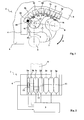
- a programming device 1 comprises coils of programming 2 which are all connected to an electronic control means 3.
- the device here comprises seven programming coils: 2a, 2b, 2c, 2d, 2e, 2f and 2g.
- These coils 2 each consist of one or more windings of wire surrounding a ferromagnetic core (not shown) and they each generate a field in a direction which is indicated by the arrows 5 (5a, 5b, 5c, 5d, 5e, 5f and 5g) on the figure 1 .
- the coils 2 are all parallel to each other and they are integral with a metal support 4 which carries housing adapted to the shapes of the different coils.
- the support 4 has a partially cylindrical surface 4a which is extended by two planes 4b and 4c.
- the coils 2 are arranged to be flush with the surfaces 4a and 4c.
- the support 4 is fixed at a munitions feed member 6 of a weapon (not shown). This support 4 partially cap a feed star 7 of this supply member.
- the projectiles 8 (fixed on their sockets) are introduced into the weapon by means of 9-link strips and they progress to the weapon chamber. by being driven by one or more stars 7.
- the stars 7 rotate (arrow ⁇ ) to drive the projectiles 8.
- the support 4 of the coils 2 is designed so that its cylindrical surface 4a surrounds the feed star 7.
- the projectiles 8 pass successively in front of the different coils 2 during their journey of the supply member 6 to receive a programming at their rocket.
- the rocket is represented diagrammatically in the form of a circle 12 in dotted lines.
- the projectile 8 its belt 11 and its rocket 12 on the figure 2 .
- This is a base rocket located behind the belt 11.
- the coils 2 are parallel to each other and also have their turns substantially parallel to the axis of the projectile 8 (the schematic forms of the coils given in FIG. the figure 2 correspond to that of the turns).
- the figure 9 schematizes more precisely such a coil with turns parallel to the axis of the projectile. It can be seen that this coil comprises a ferrite core 20 having a peripheral notch 21 in which the turns 22 are housed.
- the support 4 may therefore be positioned as here so as to be disposed in the vicinity of the caps of the projectiles (base rockets).
- the support 4 will be positioned in the vicinity of the projectile warheads. It all depends on the type of ammunition that will be implemented.
- the rocket incorporates in a conventional manner a means for receiving the programming signal transmitted by the coils.
- This means may comprise a receiver coil (or antenna) coupled to an electronic decoding of the transmitted signal.
- each projectile rocket 8 will pass successively in front of the coils 2a to 2g.
- the programming signal will be transmitted to the rocket by the various coils 2a to 2g throughout the passage of the rocket.
- the different coils are not connected in series to the electronic control means 3 but they are each individually connected to this control means 3.
- Each coil can then be powered by a means that is specific to it.
- a means that is specific to it.
- Such a means has lower power characteristics (one-seventh of the maximum power required to power all coils) and is easier to define and incorporate into a weapon system.
- the programming signal that will be emitted by each coil 2 will therefore be modulated in power as a function of the distance between the coil 2i considered and the rocket of the projectile 8.
- the position sensor 10 which is connected to the electronic control means 3.
- the position sensor 10 may consist of a coil fed by a current and which will detect the passage of the metallic mass of the projectile 8.
- the sensor 10 is positioned at the first coil 2a. It is sufficient to provide a housing in the turn of this coil 2a to set up the detection coil 10. It may also (according to a preferred embodiment) implement, not a turn, but an inductive sensor 10.
- the means for determining the position of the rocket relative to the coils also include means for determining the projectile advance speed.
- the speed of advance is easy to determine since the speed of rotation ⁇ stars is a constant value that depends on the weapon considered. This speed can therefore be incorporated in a memory of the electronic control means 3. Alternatively this speed can be measured.
- the figure 3 shows a coil 2i and two different positions 8 0 and 8 1 occupied by a projectile 8 given.
- the projectile is at time T0 at position 8 0 and at time T1 at position 8 1 .
- the movement of the projectile is a circular translational movement controlled by the feed star 7.
- the coil 2i will transmit a programming signal only between the transmission start time T0 and the end of transmission time T1.
- the start of the transmission is controlled by the electronic control means 3 when the ammunition 8 is located at a first distance d 0 Minimum 2i coil (position 8 0).
- the end of the emission is then controlled when the ammunition 8 moves away from the coil by a second minimum distance d 1 (position 8 1 ).
- angles ⁇ 0 and ⁇ 1 between the main direction of emission 5i of the coil 2i considered with the two extreme directions ⁇ 0 and ⁇ 1 which connect the axis can advantageously be considered as first and second distances.
- the coil 2i is emitting only when the projectile is between the position 8 0 and the position 8 1 .
- the maximum power is thus emitted when the coil is close to the rocket of the projectile 8.
- No programming signal is transmitted to the projectile 8 before the position 8 0 and after the position 8 1 .
- the figure 4 schematically a control means 3 for ensuring such a control mode of the different coils.
- This control means 3 comprises a power stage constituted by seven amplifiers 14a to 14g (an amplifier per coil 2) and a control stage 15 consisting of a programmable computer, for example a preprogrammed component.
- the control means 3 also comprises a power supply stage 16 (for example a battery) which powers the various amplifiers 14i and the control stage 15.
- a power supply stage 16 for example a battery
- control stage 15 incorporates a clock 17 and one or more memories 18. It also receives the signals supplied by the position sensor 10 and is connected to a programming interface 19 (a keyboard by example) by which a user enters the desired value (s) for programming the rockets.
- a programming interface 19 a keyboard by example
- the control stage 15 will be able to drive each amplifier 14i individually.
- the control of an amplification stage will consist in applying to the latter a signal ⁇ i of variable frequency and amplitude.
- the variation of the frequency of each signal ⁇ i will convey the desired programming for the rocket.
- the latter will of course incorporate a demodulation stage for rendering the received programming.
- An algorithm stored in the control stage 15 will make it possible to determine which value to give at each instant for each signal ⁇ i as a function of the programming given by the desired interface 19 and as a function of the location of the projectile with respect to each coil, location which is determined by the position sensor 10 and the means for determining the speed (speed value stored in memory or measured value provided by a specific sensor 13).
- each coil 2i will emit a continuous signal and power constant between the start time T 0 and the instant T 1 end of emission.
- the figure 5 shows the mode of operation of a device according to this first embodiment.
- the lower part of the figure shows eight timing diagrams of the signals corresponding, respectively from top to bottom, to which 10 S received by the position sensor 10 and those S 2a to S 2g emitted by coils 2a to 2g.
- All time diagrams are represented temporally synchronized. It is the same for the four configurations A, B, C and D of the device 1 which are positioned with respect to their temporal location with respect to the diagrams. On each diagram are shown in white the coils 2i which are inactive and grayed out the coils which are emitting at their maximum power.
- the configuration A shows a projectile 8 disposed substantially between the coils 2a and 2b.
- the previous projectile 8a leaves the feed star 7.
- the sensor 10 has detected a few milliseconds previously (signal S 10 ) the appearance of the projectile 8.
- This configuration A corresponds to the beginning of the emission of the maximum power by the two coils 2a and 2b. It therefore intervenes at the start of transmission T 0a and T 0b for these two coils.
- the configuration B corresponds to that of the device when the projectile 8 is facing the third coil 2c. This configuration occurs at a time which is the start of transmission T 0d for the fourth coil 2d and the end of transmission T 1a for the first coil 2a. In this configuration only the three coils 2b, 2c and 2d are emitting.
- the configuration C corresponds to that of the device when the projectile 8 is opposite the fifth coil 2e. This configuration comes at a time that is the transmission start T 0f for the sixth coil 2f and the end of transmission T 1c for the third coil 2c. In this configuration, only the three coils 2d, 2e and 2f are emitting
- the configuration D finally corresponds to that of the device when the projectile 8 is opposite the seventh and last coil 2g. This configuration occurs at a time which is the end of emission T 1e for the fifth coil 2e. In this configuration, only the last two coils 2f and 2g are emitting
- the next projectile 8b then approaches the position sensor 10 and a new detection signal S 10 will appear.
- the falling edge of this signal S 10 will both control the emission stop for the two coils 2f and 2g and the start of transmission for the two coils 2a and 2b. This instant is therefore both the transmission end T 1f and T 1g for the coils 2f and 2g and the transmission start T 0a and T 0b for the coils 2a and 2b.
- the power cycle of the coils then continues with the same temporal distributions of the different power levels for the projectile 8b.
- the content of the programming signals is not shown here and it can conventionally be different from one projectile to another depending on the operational needs that will be dictated by the firing of the weapon.
- the different vertical dashed lines represented on the diagram are spaced from each other by an increment ⁇ T which is of the order of twenty milliseconds for a feed star in 25mm caliber.
- each coil 2i will emit a continuous and progressive power signal which will grow between the start time T 0 and a median instant T M and then decrease between the median instant T M and the instant T 1 end of emission.
- each control signal ⁇ i of each amplification stage 14i a variable amplitude as a function of the advance of the projectile relative to a given coil.
- the figure 6 shows the mode of operation of a device according to this second embodiment.
- the lower part of the figure again shows the eight temporal diagrams of the corresponding signals, respectively from top to bottom, to that S 10 received by the position sensor 10 and those S 2a to S 2g emitted by the coils 2a to 2g.
- the coils 2i which are inactive, are shown in white on each diagram.
- the signals emitted by the coils having a variable power are also shown in bolded gray the coil which is emitting at its maximum power and in pale gray coils that do not emit at their maximum power.
- each coil generally follow a triangular profile. This is true for signals S 2c , S 2d , S 2e and S 2f .
- the start and end of the cycle signals have a slightly different profile in which the triangles of the signals S 2a , S 2b and S 2g are truncated.
- the transmitted power therefore increases (except for the signal S 2a ) linearly between the start of transmission T 0 and a median instant T M and then decreases linearly between this median instant T M and the end time T 1 program.
- two elementary time intervals ⁇ T separate a start of emission at zero power T 0 and a transmission at the maximum power T M.
- Two other elementary time intervals ⁇ T then separate the transmission instant T M at the maximum power and the end T 1 of the transmission.
- the power variation slopes are the same for the rising edge and the falling edge (the triangles are isosceles of height P M and base 4 ⁇ T).
- the configuration A shows a projectile 8 disposed substantially between the coils 2a and 2b.
- the previous projectile 8a leaves the feed star 7.
- the sensor 10 has detected a few milliseconds before (signal S 10 ) the appearance of the projectile 8.
- This configuration A corresponds to a start of transmission T 0a , T 0b and T 0c for the first three coils.
- the first coil 2a then emits at its maximum power P M
- the second coil 2b emits at an intermediate power equal to half of the maximum power P M
- the third coil 2c starts transmitting starting from a zero power.
- the configuration B corresponds to that at which the third coil 2c emits at its maximum power P M (grayed out in the figure) while the coils 2b and 2d which surround it emit half power P M / 2 (light gray on the figure).
- This configuration therefore occurs at a time which is both the time T Mc for the coil 2c, the end of emission time T 1a for the coil 2a and the start time T Oe for the coil 2nd.
- the configuration C corresponds to that in which the fifth coil 2e emits at its maximum power P M while the coils 2d and 2f which surround it emit at half power P M / 2. This configuration therefore occurs at a time which is both the time T Me for the 2nd coil, the end time T 1c for the coil 2c and the start time T 0g for the coil 2g.
- the configuration D finally corresponds to that in which the seventh coil 2g emits at its maximum power P M while only the previous coil 2f emits half power P M / 2.
- This configuration occurs at an instant that is both time T Mg for coil 2g and the end time of issue T first for the second coil.
- the falling edge of the signal S 10 will also control the start of transmission for the coils 2a, 2b and 2c, with the power levels described above (maximum power for the coil 2a, half power for the coil 2b and zero power for the coil 2c). This instant is therefore also the transmission start time T 0a , T 0b and T 0c .
- the power cycle of the coils then continues with the same temporal distributions of the different power levels for the projectile 8b.
- This embodiment is therefore even more economical than the previous one. Moreover, it makes it possible to limit the radiation of the programming signal at the level of the single zone in which the projectile is located.
- the projectile advance speed is not a fixed value preprogrammed but a variable value which is measured in real time.
- the projectile advance speed it is possible to simply determine the projectile advance speed by providing at least one second position sensor 10 incorporated in another reel.
- the spacings ( ⁇ i) between the different sensors 10i are known because it is a construction data.
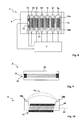
- the figure 7 thus shows six position sensors 10a, 10b, 10c, 10d, 10e and 10f each incorporated in one of the coils 2a to 2f. These position sensors will all be connected to the electronic control means 3. The latter will then incorporate a complementary algorithm making it possible to deduce the projectile 8 passing speed of the detection of the passage times of this projectile in front of two successive sensors 10 i .
- Two successive sensors make it possible to measure the speed of passage of the projectile in front of the coil immediately following the second sensor.
- six sensors 10i is perfectly located the projectile with respect to each coil.
- Such an embodiment of the invention makes it possible to overcome rather largely the definition of the weapon system (with mounting constraints close). It is no longer necessary to have speed sensors, the programming means also ensuring the location of the rocket with respect to the coils or the measurement of speed.
- the figure 8 schematically an embodiment whose operation is identical to that described above but for which the coils 2i have a different structure which is more precisely detailed in the figure 10 .
- These coils comprise a U-shaped ferrite core 20 and thus having two end poles 20a and 20b.
- the turns 22 of the coil are wound around the middle portion of the ferrite 20.
- the turns are here perpendicular to the axis of the projectile, the axis 23 of the coil is against parallel to the axis of the projectile.
- Due to the U-shape of the ferrite the generated magnetic field lines 24 extend from one pole 20a to the other pole 20b and are thus effectively directed to the rocket 12 of the projectile.
- each programming coil can be controlled individually, we can define a device in which we will apply a different programming signal at the output of the supply corridor and at the entrance of said corridor. It then becomes possible to design power devices in which the coils are distributed over greater distances and can simultaneously program several rockets with different programming signals.
- each elementary coil 2i which is at a given moment opposite the rocket of the projectile by two or more coils which will be fed simultaneously by the same signals.
- These coils, which are thus simultaneously at a given moment opposite the rocket of the projectile, are then equivalent to one and the same coil within the meaning of the present invention.
- each individual coil 2i in the case of a rectilinear corridor and to increase the energy transfer, we can replace each individual coil 2i by two coils arranged opposite each on a wall of the corridor. The projectile will then pass between these two coils. These two coils will be fed simultaneously by the control means and will be equivalent to one and the same coil within the meaning of the present invention.
- the rocket will therefore be, at its progress in the corridor, successively opposite several pairs of coils and each pair of coil will be fed by the electronic control means as a single coil according to the previously described method.
Abstract
Description
Le domaine technique de l'invention est celui des procédés et dispositifs permettant la programmation d'une fusée de projectile.The technical field of the invention is that of methods and devices for programming a projectile rocket.
Une fusée est un dispositif électronique ou électromécanique qui permet de commander la mise à feu de l'explosif de chargement du projectile.A rocket is an electronic or electromechanical device that controls the firing of the projectile charge explosive.
Les fusées peuvent être de type chronométrique ou proximétrique ou encore commander le fonctionnement à l'impact sur une cible. Elles sont parfois multi modes et permettent alors de donner au projectile, au choix de l'utilisateur, un fonctionnement à l'impact ou chronométrique.The rockets can be of chronometric or proximal type or control the operation on impact on a target. They are sometimes multi-mode and can then give the projectile, the choice of the user, an impact or chronometric operation.
Les fusées multi modes ou chronométriques doivent recevoir une programmation avant le tir. La programmation est par exemple le choix du mode de fonctionnement (fusée multi mode) et/ou le délai séparant le tir de la mise en détonation (information de chronométrie).Multi-mode or chronometric rockets must be programmed before firing. The programming is for example the choice of the operating mode (multi-mode rocket) and / or the delay between the shooting and the detonation (chronometry information).
Aujourd'hui la programmation est introduite dans la fusée le plus souvent par induction au moyen de bobines de programmation.Today programming is introduced into the rocket most often by induction by means of programming coils.
Le brevet
Ce dispositif comprend deux bobines : une bobine qui détecte l'approche d'un projectile et une bobine qui assure la programmation de la fusée. Lorsqu'un projectile est détecté par la première bobine, la deuxième bobine est activée et elle émet le signal de programmation destiné à la fusée.This device comprises two coils: a coil that detects the approach of a projectile and a coil that provides the programming of the rocket. When a projectile is detected by the first coil, the second coil is activated and it transmits the programming signal for the rocket.
Un tel dispositif met aussi en oeuvre une bobine de programmation unique qui a un profil choisi de telle sorte qu'une partie de la bobine se trouve toujours en regard de la fusée pendant une partie du mouvement de progression du projectile dans le couloir d'alimentation de l'arme. On fiabilise ainsi la programmation qui est effectuée car le signal est transmis pendant une durée de parcours du projectile qui est plus longue.Such a device also uses a single programming coil which has a chosen profile so that a part of the coil is always facing the rocket during part of the progression movement of the projectile in the supply corridor of the weapon. This improves the reliability of the programming that is carried out because the signal is transmitted during a projectile travel time that is longer.
Une telle solution est cependant très pénalisante du point de vue industriel. Le niveau d'énergie mis en oeuvre par cette bobine unique conduit à définir une électronique de commande surdimensionnée pour le besoin. Une telle électronique est difficile à intégrer en tourelle ou à proximité de la bobine de programmation.Such a solution is however very penalizing from the industrial point of view. The energy level implemented by this single coil leads to defining an oversized control electronics for the purpose. Such electronics are difficult to integrate into turrets or near the programming coil.
Par ailleurs les pertes électromagnétiques dans la structure de l'arme et le rayonnement induit sont trop forts.Moreover, the electromagnetic losses in the structure of the weapon and the induced radiation are too strong.
L'invention a pour but de proposer un procédé de programmation de fusée qui assure toujours la transmission d'un signal de programmation pendant une durée importante mais qui permette cependant de mettre en oeuvre une électronique de dimensions plus raisonnables. Le procédé selon l'invention permet également de maîtriser la programmation qui est donnée à un projectile donné tout en limitant le rayonnement électromagnétique engendré.The object of the invention is to propose a rocket programming method which always ensures the transmission of a programming signal for a long time but which nevertheless makes it possible to implement electronics of more reasonable dimensions. The method according to the invention also makes it possible to control the programming that is given to a given projectile while limiting the electromagnetic radiation generated.
Ainsi, l'invention a pour objet un procédé de programmation d'une fusée de projectile au moyen d'une bobine de programmation transmettant par induction un signal de programmation vers un moyen de réception solidaire de la fusée, procédé caractérisé en ce que le signal de programmation est transmis à partir d'au moins une deuxième bobine de programmation distincte de la première, chaque bobine étant reliée individuellement à un moyen électronique de commande et les deux bobines étant disposées de façon à pouvoir se trouver à proximité de la fusée du projectile lors du passage de ce dernier au niveau d'un moyen d'alimentation d'une arme, les bobines étant disposées de telle sorte que la fusée du projectile passe successivement devant chaque bobine.Thus, the subject of the invention is a method of programming a projectile rocket by means of a programming coil inductively transmitting a programming signal to a reception means integral with the rocket, characterized in that the signal programming is transmitted from at least a second programming coil separate from the first, each coil being individually connected to an electronic control means and the two coils being arranged so as to be close to the projectile rocket during the passage of the latter at a weapon supply means, the coils being arranged so that the rocket of the projectile passes successively in front of each coil.
Selon une caractéristique de l'invention, le signal de programmation est avantageusement modulé en puissance en fonction de la distance entre la bobine et la fusée, la puissance maximale étant délivrée par une bobine lorsque cette dernière se trouve proche de la fusée.According to one characteristic of the invention, the programming signal is advantageously modulated in power as a function of the distance between the coil and the rocket, the maximum power being delivered by a coil when the latter is close to the rocket.
Plus précisément chaque bobine pourra émettre le signal de programmation entre deux instants, un instant de début d'émission et un instant de fin d'émission, le début de l'émission étant réalisé lorsque le projectile se trouve à une première distance minimale de ladite bobine et la fin de l'émission étant provoquée lorsque le projectile s'éloigne de la bobine d'une deuxième distance minimale.More precisely, each coil may transmit the programming signal between two instants, a start of emission time and an end of transmission time, the start of the emission being made when the projectile is at a first minimum distance from said coil and the end of the emission being caused when the projectile moves away from the coil by a second minimum distance.
Selon un premier mode de réalisation, chaque bobine émet un signal continu et de puissance constante entre l'instant de début d'émission et l'instant de fin d'émission.According to a first embodiment, each coil transmits a continuous signal of constant power between the transmission start time and the emission end time.
Selon un second mode de réalisation, chaque bobine émet un signal continu et de puissance variable, au moins une bobine émettant avec une puissance qui croît entre l'instant de début d'émission et un instant médian et qui décroît entre l'instant médian et l'instant de fin d'émission.According to a second embodiment, each coil transmits a continuous signal of variable power, at least one coil emitting with a power which increases between the instant of emission start and a median instant and which decreases between the median instant and the end of emission time.
L'invention a également pour objet un dispositif de programmation permettant la mise en oeuvre de ce procédé. Ce dispositif est caractérisé en ce qu'il comprend au moins deux bobines de programmation reliées chacune individuellement à un moyen électronique de commande, bobines disposées de façon à pouvoir se trouver à proximité de la fusée du projectile lors du passage de ce dernier au niveau d'un moyen d'alimentation d'une arme, les bobines étant disposées de telle sorte que la fusée du projectile passe successivement devant chaque bobine.The invention also relates to a programming device for implementing this method. This device is characterized in that it comprises at least two programming coils each individually connected to an electronic control means, coils arranged so as to be close to the rocket of the projectile during the passage of the latter at the level of means for feeding a weapon, the coils being arranged in such a way that the rocket of the projectile passes successively in front of each reel.
Le dispositif pourra avantageusement comprendre des moyens permettant de déterminer la position de la fusée par rapport aux bobines lors de l'avance du projectile.The device may advantageously comprise means for determining the position of the rocket relative to the coils during the advance of the projectile.
Ces moyens permettant de déterminer la position de la fusée par rapport aux bobines pourront comprendre au moins un capteur de position couplé au moyen électronique de commande.These means for determining the position of the rocket relative to the coils may comprise at least one position sensor coupled to the electronic control means.
Le capteur de position pourra également être couplé à un moyen permettant de déterminer la vitesse d'avance du projectile.The position sensor may also be coupled to a means for determining the projectile advance speed.
Selon un mode particulier de réalisation, les bobines pourront être disposées au niveau d'une surface cylindrique de l'arme entourant une étoile d'alimentation, la vitesse d'avance étant déterminée à partir de la vitesse de rotation de l'étoile d'alimentation.According to a particular embodiment, the coils can be arranged at a cylindrical surface the weapon surrounding a feed star, the feed rate being determined from the speed of rotation of the feed star.
Le moyen permettant de localiser la fusée et/ou de déterminer la vitesse d'avance du projectile pourra être constitué par au moins un deuxième capteur de position relié au moyen électronique de commande.The means for locating the rocket and / or for determining the speed of advance of the projectile may be constituted by at least one second position sensor connected to the electronic control means.
L'invention sera mieux comprise à la lecture de la description qui va suivre de différents modes de réalisation, description faite en référence aux dessins annexés et dans lesquels :
- la
figure 1 est une vue schématique d'un dispositif de programmation selon l'invention mis en place au niveau d'une étoile d'un système d'alimentation en munitions d'une arme, - la
figure 2 est une autre vue schématique de ce dispositif, les bobines étant représentées en vue de dessous, - la
figure 3 montre une bobine et deux positions différentes occupées par un projectile, - la
figure 4 schématise un moyen de commande selon un mode de réalisation de l'invention, - la
figure 5 est un diagramme qui montre pour un premier mode de réalisation, d'une part les puissances en fonction du temps des signaux de programmation appliqués à chacune des bobines ainsi que différentes localisations du projectile en fonction du temps, - la
figure 6 est un diagramme analogue à celui de lafigure 5 mais pour un second mode de réalisation de l'invention, - la
figure 7 montre un dispositif de programmation selon une variante de l'invention, - la
figure 8 est une vue analogue à lafigure 2 mais mettant en oeuvre un autre type de bobine, - la
figure 9 est une vue schématisant un mode de réalisation d'une bobine mise en oeuvre par l'invention, - la
figure 10 est une vue schématisant un autre mode de réalisation d'une bobine mise en oeuvre par l'invention.
- the
figure 1 is a schematic view of a programming device according to the invention set up at the level of a star of a weapon ammunition supply system, - the
figure 2 is another schematic view of this device, the coils being shown in a view from below, - the
figure 3 shows a coil and two different positions occupied by a projectile, - the
figure 4 schematizes a control means according to one embodiment of the invention, - the
figure 5 is a diagram which shows for a first embodiment, on the one hand, the powers as a function of time of the programming signals applied to each of the coils as well as different locations of the projectile as a function of time, - the
figure 6 is a diagram similar to that of thefigure 5 but for a second embodiment of the invention, - the
figure 7 shows a programming device according to a variant of the invention, - the
figure 8 is a view similar to thefigure 2 but implementing another type of coil, - the
figure 9 is a schematic view of an embodiment of a coil implemented by the invention, - the
figure 10 is a schematic view of another embodiment of a coil implemented by the invention.
Si on se reporte aux
Les bobines 2 sont toutes parallèles les unes aux autres et elles sont solidaires d'un support 4 métallique qui porte des logements adaptés aux formes des différentes bobines.The coils 2 are all parallel to each other and they are integral with a
Le support 4 comporte une surface partiellement cylindrique 4a qui est prolongée par deux plans 4b et 4c. Les bobines 2 sont disposées de façon à être affleurantes au niveau des surfaces 4a et 4c. Le support 4 est fixé au niveau d'un organe 6 d'alimentation en munitions d'une arme (non représentée). Ce support 4 coiffe partiellement une étoile d'alimentation 7 de cet organe d'alimentation.The
D'une façon classique et bien connue de l'Homme du Métier les projectiles 8 (fixés sur leurs douilles) sont introduits dans l'arme à l'aide de bandes 9 à maillons et ils progressent jusqu'à la chambre de l'arme en étant entraînés par une ou plusieurs étoiles 7.In a conventional manner and well known to those skilled in the art, the projectiles 8 (fixed on their sockets) are introduced into the weapon by means of 9-link strips and they progress to the weapon chamber. by being driven by one or
Les étoiles 7 tournent (flèche ω) pour entraîner les projectiles 8. Le support 4 des bobines 2 est conçu de telle sorte que sa surface cylindrique 4a entoure l'étoile d'alimentation 7. Ainsi les projectiles 8 passent successivement devant les différentes bobines 2 pendant leur parcours de l'organe d'alimentation 6 pour recevoir une programmation au niveau de leur fusée.The
Sur la
Quel que soit le type de fusée (ogive ou culot) il est évident que le support 4 des bobines 2 sera positionné au niveau de l'arme de telle sorte qu'il se trouve effectivement au voisinage des fusées des projectiles considérés.Whatever the type of rocket (ogive or base) it is obvious that the
Suivant le cas le support 4 pourra donc être positionné comme ici de façon à être disposé au voisinage des culots des projectiles (fusées de culot).Depending on the case the
Pour les projectiles à fusée d'ogive on positionnera le support 4 au voisinage des ogives de projectile. Tout dépend donc du type de munition qui sera mis en oeuvre.For rocket projectiles the
La fusée incorpore d'une façon classique un moyen de réception du signal de programmation émis par les bobines. Ce moyen pourra comporter une bobine réceptrice (ou antenne) couplée à une électronique de décodage du signal transmis. Ces moyens ne font pas partie de la présente invention et ne sont donc pas décrits ici.The rocket incorporates in a conventional manner a means for receiving the programming signal transmitted by the coils. This means may comprise a receiver coil (or antenna) coupled to an electronic decoding of the transmitted signal. These means are not part of the present invention and are therefore not described here.
On constate donc que chaque fusée de projectile 8 va passer successivement devant les bobines 2a à 2g. Le signal de programmation sera transmis à la fusée par les différentes bobines 2a à 2g tout au long du passage de la fusée.It is therefore found that each
Suivant une première caractéristique de l'invention, les différentes bobines ne sont pas raccordées en série au moyen électronique de commande 3 mais elles sont chacune reliées de façon individuelle à ce moyen de commande 3.According to a first characteristic of the invention, the different coils are not connected in series to the electronic control means 3 but they are each individually connected to this control means 3.
Chaque bobine peut être alors alimentée en puissance par un moyen qui lui est spécifique. Un tel moyen a des caractéristiques de puissance plus réduites (un septième de la puissance maximale requise pour alimenter toutes les bobines) et il est plus facile à définir et à incorporer dans un système d'arme.Each coil can then be powered by a means that is specific to it. Such a means has lower power characteristics (one-seventh of the maximum power required to power all coils) and is easier to define and incorporate into a weapon system.
Il devient alors également possible de commander chaque bobine de façon individuelle. Toutes les bobines pourront être alimentées simultanément mais, selon un mode de réalisation particulier de l'invention, il devient possible de ne plus alimenter systématiquement toutes les bobines avec le courant assurant la programmation de la fusée, ce qui diminuera la puissance consommée et permettra de réduire encore la taille des moyens d'alimentation des bobines.It then becomes possible to control each coil individually. All the coils can be fed simultaneously but, according to a mode of particular embodiment of the invention, it becomes possible to no longer systematically feed all the coils with the current ensuring the programming of the rocket, which will reduce the power consumed and will further reduce the size of the coil supply means.
Selon une autre caractéristique de l'invention le signal de programmation qui sera émis par chaque bobine 2 sera donc modulé en puissance en fonction de la distance entre la bobine 2i considéré et la fusée du projectile 8.According to another characteristic of the invention, the programming signal that will be emitted by each coil 2 will therefore be modulated in power as a function of the distance between the
Il est en effet inutile d'alimenter les bobines les plus éloignées 2f et 2g lorsque le projectile 8 se trouve localisé au voisinage des bobines 2a et 2b.It is indeed useless to feed the
Conformément à l'invention des moyens sont donc prévus qui permettent de déterminer la position de la fusée par rapport aux bobines 2i lors de l'avance du projectile 8.According to the invention means are therefore provided which make it possible to determine the position of the rocket relative to the
Ces moyens comprennent ici un capteur de position 10 qui est raccordé au moyen électronique de commande 3. Le capteur de position 10 pourra être constitué par une spire alimentée par un courant et qui détectera le passage de la masse métallique du projectile 8.These means here comprise a
Le capteur 10 est positionné au niveau de la première bobine 2a. Il suffit de prévoir un logement dans la spire de cette bobine 2a pour mettre en place la spire de détection 10. On pourra également (selon un mode de réalisation préféré) mettre en oeuvre, non pas une spire, mais un capteur 10 inductif.The
Les moyens permettant de déterminer la position de la fusée par rapport aux bobines comprennent également un moyen permettant de déterminer la vitesse d'avance du projectile.The means for determining the position of the rocket relative to the coils also include means for determining the projectile advance speed.
En effet, pour maîtriser l'instant auquel une bobine est alimentée, il est nécessaire de connaître à quel instant la fusée d'un projectile donné se trouvera à une distance donnée de cette bobine.Indeed, to control the moment a coil is energized, it is necessary to know when the rocket of a given projectile will be at a given distance from this coil.
Avec le mode de réalisation décrit ici la vitesse d'avance est facile à déterminer puisque la vitesse de rotation ω des étoiles est une valeur constante qui dépend de l'arme considérée. Cette vitesse peut donc être incorporée dans une mémoire du moyen électronique de commande 3. Alternativement cette vitesse pourra être mesurée.With the embodiment described here the speed of advance is easy to determine since the speed of rotation ω stars is a constant value that depends on the weapon considered. This speed can therefore be incorporated in a memory of the electronic control means 3. Alternatively this speed can be measured.
La
Le projectile se trouve à l'instant T0 à la position 80 et à l'instant T1 à la position 81.The projectile is at time T0 at
Suivant le mode de réalisation qui est décrit ici le mouvement du projectile est un mouvement de translation circulaire commandé par l'étoile d'alimentation 7.According to the embodiment described here the movement of the projectile is a circular translational movement controlled by the
Conformément à l'invention la bobine 2i ne va émettre un signal de programmation qu'entre l'instant de début d'émission T0 et l'instant de fin d'émission T1.In accordance with the invention, the
Le début de l'émission est commandé par le moyen électronique de commande 3 lorsque la munition 8 se trouve à une première distance d0 minimale de la bobine 2i (position 80). La fin de l'émission est ensuite commandée lorsque la munition 8 s'éloigne de la bobine d'une deuxième distance minimale d1 (position 81).The start of the transmission is controlled by the electronic control means 3 when the
Avec un mouvement de translation circulaire on pourra avantageusement considérer comme première et seconde distances les angles α0 et α1 séparant la direction principale d'émission 5i de la bobine 2i considérée avec les deux directions extrêmes δ0 et δ1 qui relient l'axe du projectile 8 et l'axe 0 de l'étoile 7 lorsque le projectile se trouve aux positions extrêmes 80 et 81 pour la bobine 2i considérée.With a translational movement, the angles α 0 and α 1 between the main direction of
La bobine 2i est émettrice uniquement lorsque le projectile se trouve entre la position 80 et la position 81. La puissance maximale est donc émise lorsque la bobine se trouve proche de la fusée du projectile 8. Aucun signal de programmation n'est émis vers le projectile 8 avant la position 80 et après la position 81.The
La
Ce moyen de commande 3 comprend un étage de puissance constitué par sept amplificateurs 14a à 14g (un amplificateur par bobine 2) et un étage de commande 15 constitué par un calculateur programmable, par exemple un composant préprogrammé.This control means 3 comprises a power stage constituted by seven
Le moyen de commande 3 comprend aussi un étage d'alimentation en énergie 16 (par exemple une batterie) qui alimente en puissance les différents amplificateurs 14i ainsi que l'étage de commande 15.The control means 3 also comprises a power supply stage 16 (for example a battery) which powers the various amplifiers 14i and the
D'une façon classique, l'étage de commande 15 incorpore une horloge 17 et une ou plusieurs mémoires 18. Il reçoit par ailleurs les signaux fournis par le capteur de position 10 et il est raccordé à une interface de programmation 19 (un clavier par exemple) par lequel un utilisateur introduit la ou les valeurs souhaitées pour la programmation des fusées.In a conventional manner, the
L'étage de commande 15 va pouvoir piloter de façon individuelle chaque amplificateur 14i. D'une façon classique dans le domaine par exemple de la commande des amplificateurs audio, le pilotage d'un étage d'amplification va consister à appliquer à ce dernier un signal σi de fréquence et d'amplitude variables.The
La variation de l'amplitude de chaque signal σi va permettre de piloter l'amplitude du signal de sortie de l'amplificateur entre une valeur minimale (zéro) et une valeur maximale qui est la valeur maximale prévue par le dimensionnement de l'amplificateur.The variation of the amplitude of each signal σ i will make it possible to drive the amplitude of the output signal of the amplifier between a minimum value (zero) and a maximum value which is the maximum value provided by the sizing of the amplifier. .
La variation de la fréquence de chaque signal σi va véhiculer la programmation souhaitée pour la fusée. Cette dernière incorporera bien entendu un étage de démodulation permettant de restituer la programmation reçue.The variation of the frequency of each signal σ i will convey the desired programming for the rocket. The latter will of course incorporate a demodulation stage for rendering the received programming.
Un algorithme mis en mémoire dans l'étage de commande 15 va permettre de déterminer quelle valeur donner à chaque instant pour chaque signal σi en fonction de la programmation donnée par l'interface 19 souhaitée et en fonction de la localisation du projectile par rapport à chaque bobine, localisation qui est déterminée grâce au capteur de position 10 et aux moyens de détermination de la vitesse (valeur de vitesse mise en mémoire 18 ou valeur mesurée fournie par un capteur spécifique 13).An algorithm stored in the
Suivant un premier mode de réalisation de l'invention chaque bobine 2i émettra un signal continu et de puissance constante entre l'instant T0 de début d'émission et l'instant T1 de fin d'émission.According to a first embodiment of the invention each
La
On a représenté en partie haute de la figure quatre configurations A, B, C et D du dispositif lorsqu'un projectile 8 passe successivement devant les différentes bobines 2a à 2g.In the upper part of the figure is shown four configurations A, B, C and D of the device when a projectile 8 passes successively in front of the
La partie basse de la figure montre les huit diagrammes temporels des signaux correspondant, respectivement de haut en bas, à celui S10 reçu par le capteur de position 10 et à ceux S2a à S2g émis par les bobines 2a à 2g.The lower part of the figure shows eight timing diagrams of the signals corresponding, respectively from top to bottom, to which 10 S received by the
Tous les diagrammes temporels sont représentés synchronisés temporellement. Il en est de même pour les quatre configurations A, B, C et D du dispositif 1 qui sont positionnées en regard de leur localisation temporelle par rapport aux diagrammes. On a représenté en blanc sur chaque diagramme les bobines 2i qui sont inactives et en grisé gras les bobines qui sont émettrices à leur puissance maximale.All time diagrams are represented temporally synchronized. It is the same for the four configurations A, B, C and D of the
La configuration A montre un projectile 8 disposé sensiblement entre les bobines 2a et 2b. Le projectile précédent 8a quitte l'étoile d'alimentation 7. Le capteur 10 a détecté quelques millisecondes auparavant (signal S10) l'apparition du projectile 8. Cette configuration A correspond au début de l'émission de la puissance maximale par les deux bobines 2a et 2b. Elle intervient donc à l'instant de début d'émission T0a et T0b pour ces deux bobines.The configuration A shows a projectile 8 disposed substantially between the
La configuration B correspond à celle du dispositif lorsque le projectile 8 se trouve en regard de la troisième bobine 2c. Cette configuration intervient à un instant qui est le début d'émission T0d pour la quatrième bobine 2d et la fin d'émission T1a pour la première bobine 2a. Dans cette configuration seules les trois bobines 2b, 2c et 2d sont émettrices.The configuration B corresponds to that of the device when the
La configuration C correspond à celle du dispositif lorsque le projectile 8 se trouve en regard de la cinquième bobine 2e. Cette configuration intervient à un instant qui est le début d'émission T0f pour la sixième bobine 2f et la fin d'émission T1c pour la troisième bobine 2c. Dans cette configuration, seules les trois bobines 2d, 2e et 2f sont émettricesThe configuration C corresponds to that of the device when the
La configuration D enfin correspond à celle du dispositif lorsque le projectile 8 se trouve en regard de la septième et dernière bobine 2g. Cette configuration intervient à un instant qui est la fin d'émission T1e pour la cinquième bobine 2e. Dans cette configuration, seules les deux dernières bobines 2f et 2g sont émettricesThe configuration D finally corresponds to that of the device when the
Le projectile suivant 8b approche alors du capteur de position 10 et un nouveau signal de détection S10 va apparaître. Le front descendant de ce signal S10 va à la fois commander l'arrêt d'émission pour les deux bobines 2f et 2g et le début d'émission pour les deux bobines 2a et 2b. Cet instant est donc à la fois la fin d'émission T1f et T1g pour les bobines 2f et 2g et le début d'émission T0a et T0b pour les bobines 2a et 2b. Le cycle d'alimentation des bobines se poursuit alors avec les mêmes répartitions temporelles des différents niveaux de puissance pour le projectile 8b.The next projectile 8b then approaches the
Bien entendu le contenu des signaux de programmation n'est pas figuré ici et il pourra d'une façon classique être différent d'un projectile à l'autre en fonction des besoins opérationnels qui seront dictés par la conduite de tir de l'arme.Of course, the content of the programming signals is not shown here and it can conventionally be different from one projectile to another depending on the operational needs that will be dictated by the firing of the weapon.
Ce qui se répète conformément à l'invention c'est la répartition successive temporelle des différents niveaux de puissance des bobines 2i lors du passage d'un projectile 8 devant elles.What is repeated in accordance with the invention is the successive temporal distribution of the different power levels of the
Les différentes lignes pointillées verticales représentées sur le diagramme sont espacées les unes des autres d'un incrément δT qui est de l'ordre de la vingtaine de millisecondes pour une étoile d'alimentation en calibre 25mm.The different vertical dashed lines represented on the diagram are spaced from each other by an increment δT which is of the order of twenty milliseconds for a feed star in 25mm caliber.
On constate en considérant les diagrammes temporels qu'il n'y a jamais plus de trois bobines 2i fonctionnant simultanément et que seules deux bobines fonctionnent lors du premier et du dernier intervalle δT.It can be seen by considering the time diagrams that there are never more than three
Il en résulte une puissance maximale qui n'est que 42,8% de la puissance maximale requise lorsque toutes les bobines sont commandées. Il en résulte aussi une consommation électrique globale sur le cycle qui n'est que 38,8% de la consommation électrique des dispositifs selon l'art antérieur dans lesquels toutes les bobines sont commandées simultanément.This results in a maximum power that is only 42.8% of the maximum power required when all coils are controlled. This also results in overall power consumption on the cycle which is only 38.8% of the electrical consumption of the devices according to the prior art in which all the coils are controlled simultaneously.
Une telle économie est très appréciable dans les systèmes d'arme embarqués pour lesquels on cherche à minimiser les consommations et l'encombrement des électroniques de puissance. Par ailleurs on notera que les interférences de programmation d'un projectile à l'autre sont minimisées puisque seules les bobines extrêmes 2f et 2g sont alimentées lorsque le projectile suivant 8b approche du dispositif.Such a saving is very significant in embedded weapon systems for which it seeks to minimize consumption and congestion of power electronics. Furthermore, it will be noted that the programming interferences from one projectile to the other are minimized since only the
Suivant un second mode de réalisation de l'invention chaque bobine 2i émettra un signal continu et de puissance progressive qui croîtra entre l'instant T0 de début d'émission et un instant médian TM puis qui décroîtra entre l'instant médian TM et l'instant T1 de fin d'émission.According to a second embodiment of the invention, each
La variation de puissance sera obtenue en donnant à chaque signal de commande σi de chaque étage d'amplification 14i une amplitude variable en fonction de l'avance du projectile par rapport à une bobine donnée.The power variation will be obtained by giving each control signal σ i of each amplification stage 14i a variable amplitude as a function of the advance of the projectile relative to a given coil.
La
On a représenté comme précédemment en partie haute de la figure quatre configurations A, B, C et D du dispositif lorsqu'un projectile 8 passe successivement devant les différentes bobines 2a à 2g.As previously shown in the upper part of the figure, there are shown four configurations A, B, C and D of the device when a projectile 8 passes successively in front of the
La partie basse de la figure montre là encore les huit diagrammes temporels des signaux correspondant, respectivement de haut en bas, à celui S10 reçu par le capteur de position 10 et à ceux S2a à S2g émis par les bobines 2a à 2g.The lower part of the figure again shows the eight temporal diagrams of the corresponding signals, respectively from top to bottom, to that S 10 received by the
Tous les diagrammes temporels sont représentés synchronisés temporellement et il en est de même pour les quatre configurations A, B, C et D du dispositif 1 qui sont positionnées en regard de leur localisation temporelle par rapport aux diagrammes.All temporal diagrams are represented temporally synchronized and the same is true for the four configurations A, B, C and D of the
On a représenté en blanc sur chaque diagramme les bobines 2i qui sont inactives. Les signaux émis par les bobines ayant une puissance variable on a représenté par ailleurs en grisé gras la bobine qui est émettrice à sa puissance maximale et en grisé pâle les bobines qui n'émettent pas à leur puissance maximale.The
On voit que les puissances émises par chaque bobine suivent généralement un profil triangulaire. Cela est vrai pour les signaux S2c, S2d, S2e et S2f. Les signaux de début et fin du cycle ont un profil légèrement différent dans lequel les triangles des signaux S2a, S2b et S2g sont tronqués.It can be seen that the powers emitted by each coil generally follow a triangular profile. This is true for signals S 2c , S 2d , S 2e and S 2f . The start and end of the cycle signals have a slightly different profile in which the triangles of the signals S 2a , S 2b and S 2g are truncated.
La puissance émise croît donc (sauf pour le signal S2a) de façon linéaire entre le début d'émission T0 et un instant médian TM puis elle décroît linéairement entre cet instant médian TM et l'instant T1 de fin d'émission.The transmitted power therefore increases (except for the signal S 2a ) linearly between the start of transmission T 0 and a median instant T M and then decreases linearly between this median instant T M and the end time T 1 program.
Pour les triangles complets (signaux S2c, S2d, S2e et S2f) deux intervalles de temps élémentaires δT séparent un début d'émission à puissance nulle T0 et une émission à la puissance maximale TM. Deux autres intervalles de temps élémentaires δT séparent ensuite l'instant TM d'émission à la puissance maximale et la fin T1 de l'émission.For the complete triangles (signals S 2c , S 2d , S 2e and S 2f ), two elementary time intervals δT separate a start of emission at zero power T 0 and a transmission at the maximum power T M. Two other elementary time intervals δT then separate the transmission instant T M at the maximum power and the end T 1 of the transmission.
Les pentes de variation de puissance sont les mêmes pour le front montant et le front descendant (les triangles sont isocèles de hauteur PM et de base 4δT).The power variation slopes are the same for the rising edge and the falling edge (the triangles are isosceles of height P M and base 4δT).
La configuration A montre un projectile 8 disposé sensiblement entre les bobines 2a et 2b. Le projectile précédent 8a quitte l'étoile d'alimentation 7. Le capteur 10 a détecté quelques millisecondes auparavant (signal S10) l'apparition du projectile 8.The configuration A shows a projectile 8 disposed substantially between the
Cette configuration A correspond à un début d'émission T0a, T0b et T0c pour les trois premières bobines. Cependant la première bobine 2a émet alors à sa puissance maximale PM, la deuxième bobine 2b émet à une puissance intermédiaire égale à la moitié de la puissance maximale PM et la troisième bobine 2c commence à émettre en partant d'une puissance nulle.This configuration A corresponds to a start of transmission T 0a , T 0b and T 0c for the first three coils. However, the
La configuration B correspond à celle à laquelle la troisième bobine 2c émet à sa puissance maximale PM (grisé gras sur la figure) tandis que les bobines 2b et 2d qui l'encadrent émettent à demi puissance PM/2 (grisé léger sur la figure). Cette configuration intervient donc à un instant qui est à la fois l'instant TMc pour la bobine 2c, l'instant de fin d'émission T1a pour la bobine 2a et l'instant T0e de début d'émission pour la bobine 2e.The configuration B corresponds to that at which the
La configuration C correspond à celle dans laquelle la cinquième bobine 2e émet à sa puissance maximale PM tandis que les bobines 2d et 2f qui l'encadrent émettent à demi puissance PM/2. Cette configuration intervient donc à un instant qui est à la fois l'instant TMe pour la bobine 2e, l'instant de fin d'émission T1c pour la bobine 2c et l'instant T0g de début d'émission pour la bobine 2g.The configuration C corresponds to that in which the
La configuration D enfin correspond à celle dans laquelle la septième bobine 2g émet à sa puissance maximale PM tandis que seule la bobine précédente 2f émet à demi puissance PM/2. Cette configuration intervient donc à un instant qui est à la fois l'instant TMg pour la bobine 2g et l'instant de fin d'émission T1e pour la bobine 2e.The configuration D finally corresponds to that in which the
A l'issue d'un autre intervalle de temps δT apparaît le front descendant du signal S10 de détection par le capteur 10 d'un nouveau projectile 8b. Cette détection provoque l'arrêt de l'émission à mi-puissance par la septième bobine et correspond dont à la fois aux instants T1g et T1f.At the end of another time interval δT appears the falling edge of the signal S 10 of detection by the
Le front descendant du signal S10 va par ailleurs commander le début d'émission pour les bobines 2a, 2b et 2c, avec les niveaux de puissance décrits précédemment (puissance maximale pour la bobine 2a, demi-puissance pour la bobine 2b et puissance zéro pour la bobine 2c). Cet instant est donc également l'instant de début d'émission T0a, T0b et T0c.The falling edge of the signal S 10 will also control the start of transmission for the
Le cycle d'alimentation des bobines se poursuit alors avec les mêmes répartitions temporelles des différents niveaux de puissance pour le projectile 8b.The power cycle of the coils then continues with the same temporal distributions of the different power levels for the projectile 8b.
On constate en considérant les diagrammes temporels qu'il n'y a jamais plus de quatre bobines 2i qui fonctionnent simultanément mais avec des niveaux de puissance différents et que seules trois bobines fonctionnent lors du premier intervalle et deux bobines pour le dernier intervalle.It can be seen from the time diagrams that there are never more than four
Compte tenu des symétries des fronts montant et descendant des variations de puissance, il en résulte une puissance maximale qui n'est que 28,6% de la puissance maximale requise lorsque toutes les bobines sont commandées. Il en résulte aussi une consommation électrique globale sur le cycle qui n'est que 24,5% de la consommation électrique des dispositifs selon l'art antérieur dans lesquels toutes les bobines sont commandées simultanément.Given the symmetries of the rising and falling edges of the power variations, this results in a maximum power which is only 28.6% of the maximum power required when all the coils are controlled. This also results in an overall power consumption on the cycle which is only 24.5% of the electrical consumption of the devices according to the prior art in which all the coils are controlled simultaneously.
Ce mode de réalisation est donc encore plus économique que le précédent. Par ailleurs il permet de limiter le rayonnement du signal de programmation au niveau de la seule zone dans laquelle se trouve le projectile.This embodiment is therefore even more economical than the previous one. Moreover, it makes it possible to limit the radiation of the programming signal at the level of the single zone in which the projectile is located.
Comme cela a été précisé précédemment, il est possible de définir un dispositif dans lequel la vitesse d'avance du projectile n'est pas une valeur fixe préprogrammée mais une valeur variable qui est mesurée en temps réel.As previously stated, it is possible to define a device in which the projectile advance speed is not a fixed value preprogrammed but a variable value which is measured in real time.
Une telle solution est particulièrement utile dans certains systèmes d'arme pour lesquels la rotation de l'étoile d'alimentation n'est pas une valeur fixe.Such a solution is particularly useful in certain weapon systems for which the rotation of the feed star is not a fixed value.
On pourra pour cela mettre en oeuvre un moyen de mesure de la vitesse 13 (
Selon un autre mode de réalisation de l'invention on pourra déterminer de façon simple la vitesse d'avance du projectile en prévoyant au moins un deuxième capteur de position 10 incorporé dans une autre bobine. Les espacements (λi) entre les différents capteurs 10i sont connus car il s'agit d'une donnée de construction.According to another embodiment of the invention, it is possible to simply determine the projectile advance speed by providing at least one
Les mesures des temps de passage devant deux capteurs (10i-1, 10i) successifs permettent donc de déterminer aisément la vitesse de passage (Vi = λi / (Ti-T(i-1))) .Measurements of the passage times in front of two successive sensors (10 i-1 , 10 i ) thus make it possible to easily determine the passage velocity (Vi = λi / (T i -T (i-1) )).
La
Deux capteurs successifs permettent de mesurer la vitesse de passage du projectile devant la bobine qui suit immédiatement le deuxième capteur. En disposant comme représenté sur la
On pourra d'ailleurs, en utilisant comme ici un capteur de moins qu'il y a de bobines, simplement localiser le projectile par rapport aux bobines (sans calcul de vitesse), la détection du passage du projectile par un capteur 10i impliquant en effet nécessairement le positionnement du projectile à une distance donnée de la bobine immédiatement suivante.We can also, using as here a sensor less than there are coils, simply locate the projectile with respect to the coils (without speed calculation), the detection of the passage of the projectile by a sensor 10i involving indeed necessarily the positioning of the projectile at a given distance from the immediately following coil.
Un tel mode de réalisation de l'invention permet de s'affranchir assez largement de la définition du système d'arme (aux contraintes de montage près). Il n'est plus nécessaire ainsi de disposer des capteurs de vitesse, le moyen de programmation assurant également la localisation de la fusée par rapport aux bobines ou la mesure de la vitesse.Such an embodiment of the invention makes it possible to overcome rather largely the definition of the weapon system (with mounting constraints close). It is no longer necessary to have speed sensors, the programming means also ensuring the location of the rocket with respect to the coils or the measurement of speed.
Diverses variantes sont possibles sans sortir du cadre de l'invention.Various variants are possible without departing from the scope of the invention.
La
L'avantage d'un tel mode de réalisation est que ces bobines sont des composants standard du commerce qui sont facilement disponibles.The advantage of such an embodiment is that these coils are standard commercial components that are readily available.
D'autres modes de réalisation sont envisageables.Other embodiments are possible.
On a ainsi décrit ici un dispositif de programmation disposé au niveau d'une étoile d'alimentation, donc pour lequel les bobines 2i étaient disposées sur une portion cylindrique du dispositif d'alimentation en projectile.Thus a programming device has been described here arranged at a feed star, therefore for which the
Il est bien entendu possible de définir un dispositif selon l'invention dans lequel la programmation est réalisée au niveau d'un couloir rectiligne dans lequel les bobines se succèdent parallèlement les unes aux autres.It is of course possible to define a device according to the invention in which the programming is performed at a rectilinear corridor in which the coils succeed one another in parallel to each other.
Par ailleurs, chaque bobine de programmation pouvant être commandée de façon individuelle, on pourra définir un dispositif dans lequel on appliquera un signal de programmation différent au niveau de la sortie du couloir d'alimentation et au niveau de l'entrée dudit couloir. Il devient alors possible de concevoir des dispositifs d'alimentation dans lesquels les bobines sont réparties sur des distances supérieures et peuvent programmer simultanément plusieurs fusées avec des signaux de programmation différents.Furthermore, each programming coil can be controlled individually, we can define a device in which we will apply a different programming signal at the output of the supply corridor and at the entrance of said corridor. It then becomes possible to design power devices in which the coils are distributed over greater distances and can simultaneously program several rockets with different programming signals.
Dans certaines configurations on pourra remplacer chaque bobine élémentaire 2i qui se trouve à un instant donné en regard de la fusée du projectile par deux ou plusieurs bobines qui seront alimentées simultanément par les même signaux. Ces bobines qui se trouvent ainsi simultanément à un moment donné en regard de la fusée du projectile sont alors équivalentes à une seule et même bobine au sens de la présente invention.In certain configurations it will be possible to replace each
Par exemple, dans le cas d'un couloir rectiligne et afin d'augmenter le transfert d'énergie, on pourra remplacer chaque bobine individuelle 2i par deux bobines disposées en vis à vis chacune sur une paroi du couloir. Le projectile passera alors entre ces deux bobines. Ces deux bobines seront alimentées simultanément par le moyen de commande et seront équivalentes à une seule et même bobine au sens de la présente invention. La fusée se trouvera donc, lors de sa progression dans le couloir, successivement en regard de plusieurs paires de bobines et chaque paire de bobine sera alimentée par le moyen électronique de commande comme une seule et même bobine conformément au procédé précédemment décrit.For example, in the case of a rectilinear corridor and to increase the energy transfer, we can replace each
Claims (11)
Priority Applications (1)
| Application Number | Priority Date | Filing Date | Title |
|---|---|---|---|
| PL09290844T PL2187163T3 (en) | 2008-11-18 | 2009-11-09 | Method for programming a projectile fuse and programming device allowing the implementation of such a method |
Applications Claiming Priority (1)
| Application Number | Priority Date | Filing Date | Title |
|---|---|---|---|
| FR0806484A FR2938638A1 (en) | 2008-11-18 | 2008-11-18 | METHOD FOR PROGRAMMING A PROJECTILE ROCKET AND PROGRAMMING DEVICE FOR IMPLEMENTING SUCH A METHOD |
Publications (2)
| Publication Number | Publication Date |
|---|---|
| EP2187163A1 true EP2187163A1 (en) | 2010-05-19 |
| EP2187163B1 EP2187163B1 (en) | 2012-01-18 |
Family
ID=40848495
Family Applications (1)
| Application Number | Title | Priority Date | Filing Date |
|---|---|---|---|
| EP09290844A Active EP2187163B1 (en) | 2008-11-18 | 2009-11-09 | Method for programming a projectile fuse and programming device allowing the implementation of such a method |
Country Status (6)
| Country | Link |
|---|---|
| US (2) | US8113102B2 (en) |
| EP (1) | EP2187163B1 (en) |
| AT (1) | ATE542104T1 (en) |
| ES (1) | ES2378939T3 (en) |
| FR (1) | FR2938638A1 (en) |
| PL (1) | PL2187163T3 (en) |
Families Citing this family (8)
| Publication number | Priority date | Publication date | Assignee | Title |
|---|---|---|---|---|
| US8267000B1 (en) * | 2007-05-25 | 2012-09-18 | Survice Engineering Company | Munitions endgame geometry for optimal lethality system |
| FR2938638A1 (en) * | 2008-11-18 | 2010-05-21 | Nexter Munitions | METHOD FOR PROGRAMMING A PROJECTILE ROCKET AND PROGRAMMING DEVICE FOR IMPLEMENTING SUCH A METHOD |
| FR2952425B1 (en) * | 2009-11-06 | 2011-10-28 | Nexter Munitions | DEVICE FOR PROGRAMMING A PROJECTILE ROCKER |
| US20120296235A1 (en) * | 2011-03-29 | 2012-11-22 | Rupp Keith W | Automated system and method for performing and monitoring physical therapy exercises |
| US9432925B2 (en) * | 2013-08-05 | 2016-08-30 | Nokia Technologies Oy | Method, apparatus, and computer program product for hop count usage in cluster selection |
| SE541930C2 (en) * | 2017-09-28 | 2020-01-07 | Bae Systems Bofors Ab | Method and system for inductive programming of a fuze |
| DE102020108567A1 (en) | 2020-03-27 | 2021-09-30 | Krauss-Maffei Wegmann Gmbh & Co. Kg | Programming device |
| CN115812136A (en) * | 2020-05-12 | 2023-03-17 | Bae系统信息和电子系统集成有限公司 | Wireless multi-fuze setter interface |
Citations (4)
| Publication number | Priority date | Publication date | Assignee | Title |
|---|---|---|---|---|
| US5117733A (en) | 1990-03-15 | 1992-06-02 | Honeywell Regelsysteme Gmbh | Apparatus for setting the time fuse of a projectile |
| US5343795A (en) * | 1991-11-07 | 1994-09-06 | General Electric Co. | Settable electronic fuzing system for cannon ammunition |
| GB2350937A (en) | 1999-04-29 | 2000-12-13 | Alliant Techsystems Inc | A coil for an inductive coupling arrangement and a fuze setter system |
| EP1757894A1 (en) * | 2005-08-26 | 2007-02-28 | Rheinmetall Waffe Munition GmbH | Device for identifying the ammunition type of ammunition |
Family Cites Families (13)
| Publication number | Priority date | Publication date | Assignee | Title |
|---|---|---|---|---|
| CH589838A5 (en) * | 1975-03-10 | 1977-07-15 | Oerlikon Buehrle Ag | |
| CH598564A5 (en) * | 1976-03-09 | 1978-04-28 | Oerlikon Buehrle Ag | |
| CH619298A5 (en) * | 1978-10-30 | 1980-09-15 | Mefina Sa | |
| US4318342A (en) * | 1980-01-25 | 1982-03-09 | Aai Corporation | Ammunition with surface-mounted light-settable pickup arrangement for digital memory storage |
| US5160801A (en) * | 1991-05-20 | 1992-11-03 | Alliant Techsystems Inc. | Powerless programmable fuze function mode system |
| EP0769673B1 (en) * | 1995-09-28 | 2002-03-20 | Oerlikon Contraves Pyrotec AG | Method and device to program time fuses for projectiles |
| US6439097B1 (en) * | 1998-04-09 | 2002-08-27 | Raytheon Company | Missile launcher with piezoelectric launcher pulse power source and inductive launcher/missile coupling |
| US6557450B1 (en) * | 2002-02-13 | 2003-05-06 | The United States Of America As Represented By The Secretary Of The Navy | Power indicating setter system for inductively-fuzed munitions |
| US6666123B1 (en) * | 2002-05-30 | 2003-12-23 | Raytheon Company | Method and apparatus for energy and data retention in a guided projectile |
| US7077045B2 (en) * | 2003-09-24 | 2006-07-18 | Raytheon Company | Projectile inductive interface for the concurrent transfer of data and power |
| US20050126379A1 (en) * | 2003-12-10 | 2005-06-16 | Pikus Eugene C. | RF data communications link for setting electronic fuzes |
| US7926402B2 (en) * | 2006-11-29 | 2011-04-19 | Alliant Techsystems Inc. | Method and apparatus for munition timing and munitions incorporating same |
| FR2938638A1 (en) * | 2008-11-18 | 2010-05-21 | Nexter Munitions | METHOD FOR PROGRAMMING A PROJECTILE ROCKET AND PROGRAMMING DEVICE FOR IMPLEMENTING SUCH A METHOD |
-
2008
- 2008-11-18 FR FR0806484A patent/FR2938638A1/en active Pending
-
2009
- 2009-11-09 AT AT09290844T patent/ATE542104T1/en active
- 2009-11-09 PL PL09290844T patent/PL2187163T3/en unknown
- 2009-11-09 EP EP09290844A patent/EP2187163B1/en active Active
- 2009-11-09 ES ES09290844T patent/ES2378939T3/en active Active
- 2009-11-17 US US12/591,351 patent/US8113102B2/en active Active
-
2011
- 2011-09-23 US US13/200,410 patent/US8215220B2/en active Active
Patent Citations (4)
| Publication number | Priority date | Publication date | Assignee | Title |
|---|---|---|---|---|
| US5117733A (en) | 1990-03-15 | 1992-06-02 | Honeywell Regelsysteme Gmbh | Apparatus for setting the time fuse of a projectile |
| US5343795A (en) * | 1991-11-07 | 1994-09-06 | General Electric Co. | Settable electronic fuzing system for cannon ammunition |
| GB2350937A (en) | 1999-04-29 | 2000-12-13 | Alliant Techsystems Inc | A coil for an inductive coupling arrangement and a fuze setter system |
| EP1757894A1 (en) * | 2005-08-26 | 2007-02-28 | Rheinmetall Waffe Munition GmbH | Device for identifying the ammunition type of ammunition |
Also Published As
| Publication number | Publication date |
|---|---|
| PL2187163T3 (en) | 2012-06-29 |
| ES2378939T3 (en) | 2012-04-19 |
| US8215220B2 (en) | 2012-07-10 |
| US20120011991A1 (en) | 2012-01-19 |
| EP2187163B1 (en) | 2012-01-18 |
| FR2938638A1 (en) | 2010-05-21 |
| ATE542104T1 (en) | 2012-02-15 |
| US8113102B2 (en) | 2012-02-14 |
| US20100147141A1 (en) | 2010-06-17 |
Similar Documents
| Publication | Publication Date | Title |
|---|---|---|
| EP2187163B1 (en) | Method for programming a projectile fuse and programming device allowing the implementation of such a method | |
| EP0887613A2 (en) | In-flight programming method of the triggering moment of a projectile element, firing control and fuse for carrying out this method | |
| FR2704639A1 (en) | Electronic rocket adjustment system for a barrel ammunition. | |
| EP0028966B1 (en) | Method of piloting and guiding missiles in terminal flight | |
| CA2784775C (en) | Method and device for programming a projectile | |
| CA2725023C (en) | Apparatus and method for measurement of the muzzle velocity of a projectile or the like | |
| EP2320190B1 (en) | Device for programming a fuze of a projectile | |
| US8558151B2 (en) | Method for correcting the trajectory of a projectile, in particular of a terminal phase-guided projectile, and projectile for carrying out the method | |
| EP0273787B1 (en) | Projectile for the indirect attack of armoured vehicles | |
| FR2922008A1 (en) | DEVICE FOR REMOTE CONTROL OF A TARGET DESIGNER FROM AN ATTACK MODULE, ATTACK MODULE, AND DESIGNER EMPLOYING SUCH A DEVICE | |
| US11187496B2 (en) | Method and apparatus for improving the aim of a weapon station, firing a point-detonating or an air-burst projectile | |
| WO2014044928A1 (en) | Deviation indicator with infrared imagery and system for automatically aiming at and tracking a target | |
| FR2795171A1 (en) | TRANSMISSION COIL AND DEVICE FOR SETTING A PROJECTILE DETONATOR | |
| EP2600097B1 (en) | Method for controlling the triggering of a warhead, control device and projectile fuse implementing such a method | |
| FR2792399A1 (en) | Projectile launcher with multiple charges uses controlled time delay between charges to determine exact speed of launch | |
| EP1293751B1 (en) | Method for adjusting the ignition time of a projectile, programming device and time fuse used in such a method | |
| EP0624805A1 (en) | Method for improving weapon aiming by means of forerunner shell, and corresponding shell | |
| EP0283386B1 (en) | Remotely controlled apparatus to fire a projectile | |
| EP2175226B1 (en) | Method for controlling an attack module and attack module implementing such a method | |
| FR2715221A1 (en) | Projectile launching information magnetic feed | |
| EP1782018A1 (en) | Method and system for activating an ammunition load, ammunition equipped with a high-precision activating device and system for neutralizing a target | |
| FR2490802A1 (en) | Locating system for projectiles used in training - has ratio transmitter in projectile located during flight by two ground monitoring stations for rapid radio-goniometric site exploration | |
| EP0380390A2 (en) | Programmable and autonomous mine fuze | |
| FR2751064A1 (en) | Formed load firing detection method for use in monitoring state of mine field |
Legal Events
| Date | Code | Title | Description |
|---|---|---|---|
| PUAI | Public reference made under article 153(3) epc to a published international application that has entered the european phase |
Free format text: ORIGINAL CODE: 0009012 |
|
| AK | Designated contracting states |
Kind code of ref document: A1 Designated state(s): AT BE BG CH CY CZ DE DK EE ES FI FR GB GR HR HU IE IS IT LI LT LU LV MC MK MT NL NO PL PT RO SE SI SK SM TR |
|
| AX | Request for extension of the european patent |
Extension state: AL BA RS |
|
| 17P | Request for examination filed |
Effective date: 20101119 |
|
| GRAP | Despatch of communication of intention to grant a patent |
Free format text: ORIGINAL CODE: EPIDOSNIGR1 |
|
| GRAS | Grant fee paid |
Free format text: ORIGINAL CODE: EPIDOSNIGR3 |
|
| GRAA | (expected) grant |
Free format text: ORIGINAL CODE: 0009210 |
|
| AK | Designated contracting states |
Kind code of ref document: B1 Designated state(s): AT BE BG CH CY CZ DE DK EE ES FI FR GB GR HR HU IE IS IT LI LT LU LV MC MK MT NL NO PL PT RO SE SI SK SM TR |
|
| REG | Reference to a national code |
Ref country code: GB Ref legal event code: FG4D Free format text: NOT ENGLISH |
|
| REG | Reference to a national code |
Ref country code: CH Ref legal event code: NV Representative=s name: ING. MARCO ZARDI C/O M. ZARDI & CO. S.A. Ref country code: CH Ref legal event code: EP |
|
| REG | Reference to a national code |
Ref country code: AT Ref legal event code: REF Ref document number: 542104 Country of ref document: AT Kind code of ref document: T Effective date: 20120215 Ref country code: IE Ref legal event code: FG4D Free format text: LANGUAGE OF EP DOCUMENT: FRENCH |
|
| REG | Reference to a national code |
Ref country code: DE Ref legal event code: R096 Ref document number: 602009004742 Country of ref document: DE Effective date: 20120315 |
|
| REG | Reference to a national code |
Ref country code: NO Ref legal event code: T2 Effective date: 20120118 |
|
| REG | Reference to a national code |
Ref country code: SE Ref legal event code: TRGR |
|
| REG | Reference to a national code |
Ref country code: ES Ref legal event code: FG2A Ref document number: 2378939 Country of ref document: ES Kind code of ref document: T3 Effective date: 20120419 |
|
| REG | Reference to a national code |
Ref country code: NL Ref legal event code: VDEP Effective date: 20120118 |
|
| LTIE | Lt: invalidation of european patent or patent extension |
Effective date: 20120118 |
|
| REG | Reference to a national code |
Ref country code: PL Ref legal event code: T3 |
|
| PG25 | Lapsed in a contracting state [announced via postgrant information from national office to epo] |
Ref country code: IS Free format text: LAPSE BECAUSE OF FAILURE TO SUBMIT A TRANSLATION OF THE DESCRIPTION OR TO PAY THE FEE WITHIN THE PRESCRIBED TIME-LIMIT Effective date: 20120518 Ref country code: BG Free format text: LAPSE BECAUSE OF FAILURE TO SUBMIT A TRANSLATION OF THE DESCRIPTION OR TO PAY THE FEE WITHIN THE PRESCRIBED TIME-LIMIT Effective date: 20120418 Ref country code: LT Free format text: LAPSE BECAUSE OF FAILURE TO SUBMIT A TRANSLATION OF THE DESCRIPTION OR TO PAY THE FEE WITHIN THE PRESCRIBED TIME-LIMIT Effective date: 20120118 Ref country code: HR Free format text: LAPSE BECAUSE OF FAILURE TO SUBMIT A TRANSLATION OF THE DESCRIPTION OR TO PAY THE FEE WITHIN THE PRESCRIBED TIME-LIMIT Effective date: 20120118 Ref country code: NL Free format text: LAPSE BECAUSE OF FAILURE TO SUBMIT A TRANSLATION OF THE DESCRIPTION OR TO PAY THE FEE WITHIN THE PRESCRIBED TIME-LIMIT Effective date: 20120118 |
|
| REG | Reference to a national code |
Ref country code: IE Ref legal event code: FD4D |
|
| PG25 | Lapsed in a contracting state [announced via postgrant information from national office to epo] |
Ref country code: GR Free format text: LAPSE BECAUSE OF FAILURE TO SUBMIT A TRANSLATION OF THE DESCRIPTION OR TO PAY THE FEE WITHIN THE PRESCRIBED TIME-LIMIT Effective date: 20120419 Ref country code: PT Free format text: LAPSE BECAUSE OF FAILURE TO SUBMIT A TRANSLATION OF THE DESCRIPTION OR TO PAY THE FEE WITHIN THE PRESCRIBED TIME-LIMIT Effective date: 20120518 Ref country code: LV Free format text: LAPSE BECAUSE OF FAILURE TO SUBMIT A TRANSLATION OF THE DESCRIPTION OR TO PAY THE FEE WITHIN THE PRESCRIBED TIME-LIMIT Effective date: 20120118 Ref country code: FI Free format text: LAPSE BECAUSE OF FAILURE TO SUBMIT A TRANSLATION OF THE DESCRIPTION OR TO PAY THE FEE WITHIN THE PRESCRIBED TIME-LIMIT Effective date: 20120118 |
|
| REG | Reference to a national code |
Ref country code: AT Ref legal event code: MK05 Ref document number: 542104 Country of ref document: AT Kind code of ref document: T Effective date: 20120118 |
|
| PG25 | Lapsed in a contracting state [announced via postgrant information from national office to epo] |
Ref country code: CY Free format text: LAPSE BECAUSE OF FAILURE TO SUBMIT A TRANSLATION OF THE DESCRIPTION OR TO PAY THE FEE WITHIN THE PRESCRIBED TIME-LIMIT Effective date: 20120118 |
|
| PG25 | Lapsed in a contracting state [announced via postgrant information from national office to epo] |
Ref country code: CZ Free format text: LAPSE BECAUSE OF FAILURE TO SUBMIT A TRANSLATION OF THE DESCRIPTION OR TO PAY THE FEE WITHIN THE PRESCRIBED TIME-LIMIT Effective date: 20120118 Ref country code: IE Free format text: LAPSE BECAUSE OF FAILURE TO SUBMIT A TRANSLATION OF THE DESCRIPTION OR TO PAY THE FEE WITHIN THE PRESCRIBED TIME-LIMIT Effective date: 20120118 Ref country code: EE Free format text: LAPSE BECAUSE OF FAILURE TO SUBMIT A TRANSLATION OF THE DESCRIPTION OR TO PAY THE FEE WITHIN THE PRESCRIBED TIME-LIMIT Effective date: 20120118 Ref country code: DK Free format text: LAPSE BECAUSE OF FAILURE TO SUBMIT A TRANSLATION OF THE DESCRIPTION OR TO PAY THE FEE WITHIN THE PRESCRIBED TIME-LIMIT Effective date: 20120118 Ref country code: RO Free format text: LAPSE BECAUSE OF FAILURE TO SUBMIT A TRANSLATION OF THE DESCRIPTION OR TO PAY THE FEE WITHIN THE PRESCRIBED TIME-LIMIT Effective date: 20120118 Ref country code: SI Free format text: LAPSE BECAUSE OF FAILURE TO SUBMIT A TRANSLATION OF THE DESCRIPTION OR TO PAY THE FEE WITHIN THE PRESCRIBED TIME-LIMIT Effective date: 20120118 |
|
| PLBE | No opposition filed within time limit |
Free format text: ORIGINAL CODE: 0009261 |
|
| STAA | Information on the status of an ep patent application or granted ep patent |
Free format text: STATUS: NO OPPOSITION FILED WITHIN TIME LIMIT |
|
| PG25 | Lapsed in a contracting state [announced via postgrant information from national office to epo] |
Ref country code: SK Free format text: LAPSE BECAUSE OF FAILURE TO SUBMIT A TRANSLATION OF THE DESCRIPTION OR TO PAY THE FEE WITHIN THE PRESCRIBED TIME-LIMIT Effective date: 20120118 |
|
| 26N | No opposition filed |
Effective date: 20121019 |
|
| PG25 | Lapsed in a contracting state [announced via postgrant information from national office to epo] |
Ref country code: AT Free format text: LAPSE BECAUSE OF FAILURE TO SUBMIT A TRANSLATION OF THE DESCRIPTION OR TO PAY THE FEE WITHIN THE PRESCRIBED TIME-LIMIT Effective date: 20120118 |
|
| REG | Reference to a national code |
Ref country code: DE Ref legal event code: R097 Ref document number: 602009004742 Country of ref document: DE Effective date: 20121019 |
|
| BERE | Be: lapsed |
Owner name: NEXTER MUNITIONS Effective date: 20121130 |
|
| PG25 | Lapsed in a contracting state [announced via postgrant information from national office to epo] |
Ref country code: BE Free format text: LAPSE BECAUSE OF NON-PAYMENT OF DUE FEES Effective date: 20121130 |
|
| PG25 | Lapsed in a contracting state [announced via postgrant information from national office to epo] |
Ref country code: MT Free format text: LAPSE BECAUSE OF FAILURE TO SUBMIT A TRANSLATION OF THE DESCRIPTION OR TO PAY THE FEE WITHIN THE PRESCRIBED TIME-LIMIT Effective date: 20120118 |
|
| PG25 | Lapsed in a contracting state [announced via postgrant information from national office to epo] |
Ref country code: TR Free format text: LAPSE BECAUSE OF FAILURE TO SUBMIT A TRANSLATION OF THE DESCRIPTION OR TO PAY THE FEE WITHIN THE PRESCRIBED TIME-LIMIT Effective date: 20120118 Ref country code: MC Free format text: LAPSE BECAUSE OF NON-PAYMENT OF DUE FEES Effective date: 20121130 |
|
| PG25 | Lapsed in a contracting state [announced via postgrant information from national office to epo] |
Ref country code: SM Free format text: LAPSE BECAUSE OF FAILURE TO SUBMIT A TRANSLATION OF THE DESCRIPTION OR TO PAY THE FEE WITHIN THE PRESCRIBED TIME-LIMIT Effective date: 20120118 Ref country code: LU Free format text: LAPSE BECAUSE OF NON-PAYMENT OF DUE FEES Effective date: 20121109 |
|
| PG25 | Lapsed in a contracting state [announced via postgrant information from national office to epo] |
Ref country code: HU Free format text: LAPSE BECAUSE OF FAILURE TO SUBMIT A TRANSLATION OF THE DESCRIPTION OR TO PAY THE FEE WITHIN THE PRESCRIBED TIME-LIMIT Effective date: 20091109 |
|
| PG25 | Lapsed in a contracting state [announced via postgrant information from national office to epo] |
Ref country code: MK Free format text: LAPSE BECAUSE OF FAILURE TO SUBMIT A TRANSLATION OF THE DESCRIPTION OR TO PAY THE FEE WITHIN THE PRESCRIBED TIME-LIMIT Effective date: 20120118 |
|
| REG | Reference to a national code |
Ref country code: FR Ref legal event code: PLFP Year of fee payment: 7 |
|
| REG | Reference to a national code |
Ref country code: FR Ref legal event code: PLFP Year of fee payment: 8 |
|
| REG | Reference to a national code |
Ref country code: FR Ref legal event code: PLFP Year of fee payment: 9 |
|
| PGFP | Annual fee paid to national office [announced via postgrant information from national office to epo] |
Ref country code: PL Payment date: 20171023 Year of fee payment: 9 |
|
| REG | Reference to a national code |
Ref country code: FR Ref legal event code: PLFP Year of fee payment: 10 |
|
| PG25 | Lapsed in a contracting state [announced via postgrant information from national office to epo] |
Ref country code: PL Free format text: LAPSE BECAUSE OF NON-PAYMENT OF DUE FEES Effective date: 20181109 |
|
| PGFP | Annual fee paid to national office [announced via postgrant information from national office to epo] |
Ref country code: GB Payment date: 20231019 Year of fee payment: 15 |
|
| PGFP | Annual fee paid to national office [announced via postgrant information from national office to epo] |
Ref country code: ES Payment date: 20231201 Year of fee payment: 15 |
|
| PGFP | Annual fee paid to national office [announced via postgrant information from national office to epo] |
Ref country code: SE Payment date: 20231020 Year of fee payment: 15 Ref country code: NO Payment date: 20231023 Year of fee payment: 15 Ref country code: IT Payment date: 20231019 Year of fee payment: 15 Ref country code: FR Payment date: 20231019 Year of fee payment: 15 Ref country code: DE Payment date: 20231019 Year of fee payment: 15 Ref country code: CH Payment date: 20231201 Year of fee payment: 15 |