EP2187150A2 - Refrigerating Cycle - Google Patents
Refrigerating Cycle Download PDFInfo
- Publication number
- EP2187150A2 EP2187150A2 EP09175357A EP09175357A EP2187150A2 EP 2187150 A2 EP2187150 A2 EP 2187150A2 EP 09175357 A EP09175357 A EP 09175357A EP 09175357 A EP09175357 A EP 09175357A EP 2187150 A2 EP2187150 A2 EP 2187150A2
- Authority
- EP
- European Patent Office
- Prior art keywords
- temperature
- expansion valve
- refrigerant
- refrigerating cycle
- compressor
- Prior art date
- Legal status (The legal status is an assumption and is not a legal conclusion. Google has not performed a legal analysis and makes no representation as to the accuracy of the status listed.)
- Withdrawn
Links
- 239000003507 refrigerant Substances 0.000 claims abstract description 80
- 230000000694 effects Effects 0.000 description 8
- 230000015556 catabolic process Effects 0.000 description 5
- 238000006731 degradation reaction Methods 0.000 description 5
- 238000004891 communication Methods 0.000 description 4
- 238000000034 method Methods 0.000 description 4
- 230000002093 peripheral effect Effects 0.000 description 3
- 238000007634 remodeling Methods 0.000 description 3
- 238000007789 sealing Methods 0.000 description 3
- 238000003780 insertion Methods 0.000 description 2
- 230000037431 insertion Effects 0.000 description 2
- 238000001816 cooling Methods 0.000 description 1
- 239000007791 liquid phase Substances 0.000 description 1
- 238000005192 partition Methods 0.000 description 1
- 239000012808 vapor phase Substances 0.000 description 1
Images



Classifications
-
- F—MECHANICAL ENGINEERING; LIGHTING; HEATING; WEAPONS; BLASTING
- F25—REFRIGERATION OR COOLING; COMBINED HEATING AND REFRIGERATION SYSTEMS; HEAT PUMP SYSTEMS; MANUFACTURE OR STORAGE OF ICE; LIQUEFACTION SOLIDIFICATION OF GASES
- F25B—REFRIGERATION MACHINES, PLANTS OR SYSTEMS; COMBINED HEATING AND REFRIGERATION SYSTEMS; HEAT PUMP SYSTEMS
- F25B40/00—Subcoolers, desuperheaters or superheaters
-
- F—MECHANICAL ENGINEERING; LIGHTING; HEATING; WEAPONS; BLASTING
- F25—REFRIGERATION OR COOLING; COMBINED HEATING AND REFRIGERATION SYSTEMS; HEAT PUMP SYSTEMS; MANUFACTURE OR STORAGE OF ICE; LIQUEFACTION SOLIDIFICATION OF GASES
- F25B—REFRIGERATION MACHINES, PLANTS OR SYSTEMS; COMBINED HEATING AND REFRIGERATION SYSTEMS; HEAT PUMP SYSTEMS
- F25B41/00—Fluid-circulation arrangements
- F25B41/30—Expansion means; Dispositions thereof
- F25B41/31—Expansion valves
- F25B41/33—Expansion valves with the valve member being actuated by the fluid pressure, e.g. by the pressure of the refrigerant
- F25B41/335—Expansion valves with the valve member being actuated by the fluid pressure, e.g. by the pressure of the refrigerant via diaphragms
-
- F—MECHANICAL ENGINEERING; LIGHTING; HEATING; WEAPONS; BLASTING
- F25—REFRIGERATION OR COOLING; COMBINED HEATING AND REFRIGERATION SYSTEMS; HEAT PUMP SYSTEMS; MANUFACTURE OR STORAGE OF ICE; LIQUEFACTION SOLIDIFICATION OF GASES
- F25B—REFRIGERATION MACHINES, PLANTS OR SYSTEMS; COMBINED HEATING AND REFRIGERATION SYSTEMS; HEAT PUMP SYSTEMS
- F25B2309/00—Gas cycle refrigeration machines
- F25B2309/06—Compression machines, plants or systems characterised by the refrigerant being carbon dioxide
- F25B2309/061—Compression machines, plants or systems characterised by the refrigerant being carbon dioxide with cycle highest pressure above the supercritical pressure
-
- F—MECHANICAL ENGINEERING; LIGHTING; HEATING; WEAPONS; BLASTING
- F25—REFRIGERATION OR COOLING; COMBINED HEATING AND REFRIGERATION SYSTEMS; HEAT PUMP SYSTEMS; MANUFACTURE OR STORAGE OF ICE; LIQUEFACTION SOLIDIFICATION OF GASES
- F25B—REFRIGERATION MACHINES, PLANTS OR SYSTEMS; COMBINED HEATING AND REFRIGERATION SYSTEMS; HEAT PUMP SYSTEMS
- F25B2341/00—Details of ejectors not being used as compression device; Details of flow restrictors or expansion valves
- F25B2341/06—Details of flow restrictors or expansion valves
- F25B2341/068—Expansion valves combined with a sensor
- F25B2341/0683—Expansion valves combined with a sensor the sensor is disposed in the suction line and influenced by the temperature or the pressure of the suction gas
-
- F—MECHANICAL ENGINEERING; LIGHTING; HEATING; WEAPONS; BLASTING
- F25—REFRIGERATION OR COOLING; COMBINED HEATING AND REFRIGERATION SYSTEMS; HEAT PUMP SYSTEMS; MANUFACTURE OR STORAGE OF ICE; LIQUEFACTION SOLIDIFICATION OF GASES
- F25B—REFRIGERATION MACHINES, PLANTS OR SYSTEMS; COMBINED HEATING AND REFRIGERATION SYSTEMS; HEAT PUMP SYSTEMS
- F25B2700/00—Sensing or detecting of parameters; Sensors therefor
- F25B2700/21—Temperatures
- F25B2700/2115—Temperatures of a compressor or the drive means therefor
- F25B2700/21151—Temperatures of a compressor or the drive means therefor at the suction side of the compressor
Definitions
- the present invention relates to a refrigerating cycle used for a car air-conditioner and the like, and particularly relates to a refrigerating cycle including a compressor, a condenser, an evaporator, an internal heat exchanger, and an expansion valve, wherein a heat exchange is carried out between a high-temperature refrigerant introduced from the condenser to the expansion valve and a low-temperature refrigerant introduced from the evaporator to the suction side of the compressor in the internal heat exchanger.
- a refrigerating cycle illustrated in Fig. 9 has been proposed and practically used in order to improve refrigerating capacity, etc. That is, a refrigerating cycle 10 illustrated in Fig. 9 includes a compressor 101, a condenser 102, an evaporator 103, an internal heat exchanger 104, and an expansion valve 110 (which will be described below).
- a heat exchange is carried out between a high-temperature and high-pressure refrigerant (liquid phase) introduced from the condenser 102 to the expansion valve 110 and a low-temperature and low-pressure refrigerant (vapor phase) introduced from the evaporator 103 to the suction side of the compressor 101 in the internal heat exchanger 104.
- a high-temperature and high-pressure refrigerant liquid phase
- a low-temperature and low-pressure refrigerant vapor phase
- the expansion valve 110 illustrated in Fig. 10 includes an inflow orifice 21 and a valve chamber 24 at a lower part of a valve main body 20.
- the inflow orifice 21 is for introducing a high-temperature refrigerant from the internal heat exchanger 104, and the valve chamber 24 has a valve seat part 25 (a valve port 26).
- the expansion valve 110 further includes an outflow orifice 22 at a center part of the valve main body 20.
- the expansion valve 110 further includes a temperature-sensitive inflow orifice 31 and an outflow orifice 32 at the left and right of an upper part of the valve main body 20.
- the expansion valve 110 further includes a diaphragm device 40 as a temperature-sensitive and pressure-sensitive responding means at the uppermost part of the valve main body 20, and the diaphragm device 40 responds to a temperature change and a pressure change of a refrigerant flowing from the temperature-sensitive inflow orifice 31 to the outflow orifice 32.
- a diaphragm device 40 as a temperature-sensitive and pressure-sensitive responding means at the uppermost part of the valve main body 20, and the diaphragm device 40 responds to a temperature change and a pressure change of a refrigerant flowing from the temperature-sensitive inflow orifice 31 to the outflow orifice 32.
- a ball valve body 30 for opening and closing the valve port 26 and a coil spring 27 for urging the ball valve body 30 toward the valve closing direction are arranged.
- the diaphragm device 40 has a diaphragm 42 for driving the ball valve body 30 in the opening and closing direction (the vertical direction) through a drive rod 35 and a connector 36.
- An upper pressure chamber 43 and a lower pressure chamber 44 are partitioned at the upper and lower sides of the diaphragm 42 used as a partition wall.
- the upper pressure chamber 43 encloses gas at a predetermined pressure, and is sealed by a cap 46.
- the lower pressure chamber 44 communicates with the temperature-sensitive inflow orifice 31 and the outflow orifice 32 through a communication opening 45, and pressure of the low-temperature refrigerant introduced from the evaporator 103 to the internal heat exchanger 104 acts on the lower face side of the diaphragm 42.
- a hole 38 is formed near an internal center part of the valve main body 20 where the drive rod 35 penetrates, and an O-ring 39 as a sealing member is interposed between an inner peripheral face of the hole 38 and an outer peripheral face of the drive rod 35.
- a spring pressure-adjusting nut 28 is screwed to a lower part of the valve chamber 24, and an O-ring 29 as a sealing member is interposed between a not-screwed part of the spring pressure-adjusting nut 28 and an inner peripheral face of the valve chamber 24.
- a flow rate (a pressure drop rate and a temperature drop rate) of the refrigerant introduced from the outflow orifice 22 to the evaporator 103 is adjusted responding to a temperature and pressure of the low-temperature refrigerant before carrying out a heat exchange in the internal heat exchanger 104.
- Japanese Patent Application Laid-Open No. 2000-346466 discusses a method of detecting refrigerant temperature at a suction side of a compressor and adjusting the amount of a refrigerant flowing in an internal heat exchanger by a three-way valve.
- this method needs the three-way valve, a piping system becomes to be complicated and the number of parts tends to increase.
- Japanese Patent Application Laid-Open No. 2007-240041 discusses a method of providing a bypass passage at an expansion valve and cooling a refrigerant.
- this method when a load to the system fluctuates, refrigerant temperature at the compressor suction side cannot be controlled, and a structure of the expansion valve becomes to be complicated to increase cost.
- the present invention is to solve the aforementioned problems, and is directed to provide a refrigerating cycle capable of certainly and effectively suppressing an excessive increase of refrigerant temperature at the suction side of the compressor without complicating a piping system and a structure of an expansion valve.
- a refrigerating cycle of the present invention basically includes a compressor, a condenser, an evaporator, an internal heat exchanger, and an expansion valve.
- a heat exchange is carried out between a high-temperature refrigerant introduced from the condenser to the expansion valve and a low-temperature refrigerant introduced from the evaporator to the suction side of the compressor.
- a temperature-sensitive cylinder and/or an external pressure introduction pipe are additionally provided at the expansion valve.
- a flowing rate of a refrigerant introduced to the evaporator is adjusted responding to temperature and/or pressure of a low-temperature refrigerant after the heat exchange.
- the expansion valve includes a drive means such as a diaphragm device which drives a valve body in opening and closing directions responding to a pressure change of a low-temperature refrigerant introduced through the external pressure introduction pipe after carrying out the heat exchange.
- a drive means such as a diaphragm device which drives a valve body in opening and closing directions responding to a pressure change of a low-temperature refrigerant introduced through the external pressure introduction pipe after carrying out the heat exchange.
- the expansion valve includes a drive means such as a diaphragm device which drives a valve body in the opening and closing directions responding to a temperature change of a low-temperature refrigerant detected by the temperature-sensitive cylinder after carrying out the heat exchange.
- a drive means such as a diaphragm device which drives a valve body in the opening and closing directions responding to a temperature change of a low-temperature refrigerant detected by the temperature-sensitive cylinder after carrying out the heat exchange.
- the refrigerating cycle includes the temperature-sensitive cylinder and/or the external refrigerant pressure introduction pipe for detecting the temperature and/or pressure of the low-temperature refrigerant introduced toward the suction side of the compressor after carrying out the heat exchange in the internal heat exchanger.
- a flowing rate (a pressure drop rate and a temperature drop rate) of the refrigerant introduced to the evaporator is adjusted responding to temperature and/or pressure of the low-temperature refrigerant after the heat exchange.
- the refrigerating cycle of the present invention can acquire the aforementioned effect only by slightly remodeling a currently used refrigerating cycle and an expansion valve used in it, so that there is a merit that the present invention does not greatly increase cost.
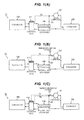
- Figs. 1(A), 1(B), and 1(C) illustrate a first exemplary embodiment, a second exemplary embodiment, and a third exemplary embodiment respectively of a refrigerating cycle according to the present invention.
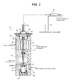
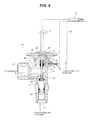
- Figs. 2 , 3 and 4 illustrate expansion valves 111, 112 and 113 used in the first, second and third exemplary embodiments respectively.
- refrigerating cycles 11, 12, and 13 illustrated in Figs. 1(A), 1(B), and 1(C) and as for the expansion valves 111, 112, and 113 illustrated in Figs. 2 to 4 , same reference numerals are given to parts corresponding to respective parts of the conventional example of the refrigerating cycle 10 and the expansion valve 110 used therein, which are illustrated in Figs. 9 and 10 , and differences from the conventional example will be mainly described below.
- an external pressure introduction pipe 50 is connected to an intermediate part of a pipe 125 connecting the internal heat exchanger 104 and the suction side of the compressor 101.
- Another end of the external pressure introduction pipe 50 is connected with a pressure introducing passage 54 provided near a bottom part of a lower pressure chamber 44 of the expansion valve 111.
- a flowing rate (a pressure drop rate and a temperature drop rate) of the refrigerant introduced to an evaporator 103 is adjusted responding to pressure of the low-temperature refrigerant after the heat exchange.
- a communication opening 45 of the conventional example is changed to a rod insertion hole 62 having a small diameter.
- An O-ring 63 as a sealing member is interposed between the rod insertion hole 62 and a drive rod 35, and the pressure of the low-temperature refrigerant after carrying out the heat exchange in the internal heat exchanger 104 is introduced into the lower pressure chamber 44 through the external pressure introduction pipe 50 and the pressure introduction passage 54.
- the refrigerating cycle 11 of this exemplary embodiment includes the external refrigerant pressure introduction pipe 50 for detecting pressure of the low-temperature refrigerant introduced toward the suction side of the compressor 101 after carrying out the heat exchange in the internal heat exchanger 104.
- the expansion valve 111 the flowing rate of the refrigerant introduced to the evaporator 103 is adjusted responding to the pressure of the low-temperature refrigerant after the heat exchange.
- the refrigerating cycle of this exemplary embodiment can acquire the aforementioned effect only by slightly remodeling a currently used refrigerating cycle and an expansion valve used in the refrigerating cycle, so that there is a merit that the present invention does not greatly increase cost.
- a temperature-sensitive cylinder 70 is arranged closely to a pipe 125 connecting the internal heat exchanger 104 and the suction side of the compressor 101. Further, as illustrated in Fig. 3 , the temperature-sensitive cylinder 70 and an upper pressure chamber 43 of the expansion valve 112 are connected with a capillary tube 72, and a flowing rate of the refrigerant introduced to an evaporator 103 is adjusted responding to temperature of the low-temperature refrigerant after the heat exchange in the expansion valve 112.
- the refrigerating cycle 12 having this configuration includes the temperature-sensitive cylinder 70 to detect the temperature of the low-temperature refrigerant introduced to the suction side of the compressor 101 after carrying out the heat exchange in the internal heat exchanger 104, and the flowing rate of the refrigerant introduced to the evaporator 103 is adjusted responding to the temperature of the low-temperature refrigerant after the heat exchange in the expansion valve 112.
- an excessive increase of the refrigerant temperature at the suction side of the compressor 101 can be certainly and effectively suppressed without complicating a piping system and a structure of the expansion valve, like the first exemplary embodiment. Therefore, since an excessive increase of (discharge) temperature in the compressor can be previously prevented, oil contained in the refrigerant can be prevented from degradation, and thus faults such as burn-out can be prevented.
- the refrigerating cycle of this exemplary embodiment can acquire the aforementioned effect only by slightly remodeling a currently used refrigerating cycle and an expansion valve used in the refrigerating cycle, so that there also is a merit that the present invention does not greatly increase cost.
- the refrigerating cycle 13 of the third exemplary embodiment is a combination of the refrigerating cycle 11 of the first exemplary embodiment and the refrigerating cycle 12 of the second exemplary embodiment.
- the refrigerating cycle 13 includes both the external pressure introduction pipe 50 and the temperature-sensitive cylinder 70.
- a configuration around the lower pressure chamber 44 of an expansion valve 113 used therefore is approximately similar to the configuration of the first exemplary embodiment, and a configuration around the upper pressure chamber 43 is approximately similar to the configuration of the second exemplary embodiment.
- a flowing rate of the refrigerant introduced to an evaporator 103 is adjusted responding to temperature and pressure of the low-temperature refrigerant after the heat exchange.
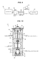
- Figs. 5(A), 5(B) and 5(C) illustrate a fourth exemplary embodiment, a fifth exemplary embodiment, and a sixth exemplary embodiment of a refrigerating cycle according to the present invention.
- Fig. 6 illustrates an expansion valve 114 used in the fourth exemplary embodiment.
- Fig. 7 illustrates an expansion valve 115 used in the fifth exemplary embodiment.
- Fig. 8 illustrates an expansion valve 116 used in the sixth exemplary embodiment.
- the refrigerating cycles 14 15 and 16 illustrated in Figs. 5(A), 5(B), and 5(C)
- the expansion valves 114, 115, and 116 used in the refrigerating cycles 14, 15, and 16 of the fourth, fifth, and sixth exemplary embodiments do not include the temperature-sensitive inflow orifice 31 and the outflow orifice 32, which are provided in the expansion valves 111, 112, and 113 used in the refrigerating cycles 11, 12, and 13 of the first, second, and third exemplary embodiments.
- a low-temperature refrigerant introduced from an evaporator 103 does not pass the insides of the expansion valves 114, 115 and 116, but is directly introduced to an internal heat exchanger 104.
- the refrigerating cycle 14 of the fourth exemplary embodiment is similar to the refrigerating cycle 12 of the second exemplary embodiment regarding described below.
- a temperature-sensitive cylinder 70 is arranged closely to a pipe 125 connecting the internal heat exchanger 104 and the suction side of the compressor 101. Further, as illustrated in Fig.
- a valve main body 20 of the expansion valve 114 used in this exemplary embodiment includes an internal pressure passage 66 for communicating between the lower pressure chamber 44 and the outflow orifice 22.
- a temperature-sensitive cylinder usually detects the refrigerant temperature near the outflow orifice of the evaporator 103 (refer to Fig. 5(B) ).
- the temperature-sensitive cylinder 70 detects the refrigerant temperature after carrying out the heat exchange in the internal heat exchanger 104. That is, it is characterized that a position of the temperature-sensitive cylinder 70 is changed.
- the refrigerating cycle 14 having the aforementioned configuration can acquire effects which are approximately similar to the effects of the refrigerating cycle 12 of the second exemplary embodiment.
- the refrigerating cycle 15 of the fifth exemplary embodiment is similar to the refrigerating cycle 11 of the first exemplary embodiment regarding described below.
- the refrigerating cycle 15 in order to detect pressure of a low-temperature refrigerant introduced to the suction side of a compressor 101 after carrying out a heat exchange in an internal heat exchanger 104, one end of the external pressure introduction pipe 50 is connected with the intermediate part of the pipe 125 connecting the internal heat exchanger 104 and the suction side of the compressor 101.
- Another end of the external pressure introduction pipe 50 is connected with a L-shaped pressure introducing passage 54 for communicating between a lower pressure chamber 44 of the expansion valve 115 and the external.
- a flowing rate of a refrigerant introduced to an evaporator 103 is adjusted responding to pressure of the low-temperature refrigerant after the heat exchange.
- the temperature-sensitive cylinder 70 is arranged closely to a pipe 124 (near an outflow orifice of the evaporator 103) for connecting the evaporator 103 and the internal heat exchanger 104, and the temperature-sensitive cylinder 70 and an upper pressure chamber 43 of the expansion valve 115 are connected with a capillary tube 72.
- the refrigerating cycle 15 having the aforementioned configuration can acquire effects which are approximately similar to the effects of the refrigerating cycle 11 of the first exemplary embodiment.
- the refrigerating cycle 16 of the sixth exemplary embodiment is a combination of the refrigerating cycle 14 of the fourth exemplary embodiment and the refrigerating cycle 15 of the fifth exemplary embodiment.
- the refrigerating cycle 16 includes both the external pressure introduction pipe 50 and the temperature-sensitive cylinder 70.
- a configuration around the lower pressure chamber 44 of the expansion valve 116 used in the refrigerating cycle 16 is approximately similar to the configuration of the fifth exemplary embodiment, and a configuration around the upper pressure chamber 43 is approximately similar to the configuration of the fourth exemplary embodiment.
- a flowing rate of a refrigerant introduced to an evaporator 103 is adjusted responding to the pressure and temperature of the low-temperature refrigerant after the heat exchange.
Landscapes
- Engineering & Computer Science (AREA)
- Physics & Mathematics (AREA)
- Mechanical Engineering (AREA)
- Thermal Sciences (AREA)
- General Engineering & Computer Science (AREA)
- Fluid Mechanics (AREA)
- Temperature-Responsive Valves (AREA)
- Compression-Type Refrigeration Machines With Reversible Cycles (AREA)
Abstract
Description
- The present invention relates to a refrigerating cycle used for a car air-conditioner and the like, and particularly relates to a refrigerating cycle including a compressor, a condenser, an evaporator, an internal heat exchanger, and an expansion valve, wherein a heat exchange is carried out between a high-temperature refrigerant introduced from the condenser to the expansion valve and a low-temperature refrigerant introduced from the evaporator to the suction side of the compressor in the internal heat exchanger.
- As for an example of a conventional refrigerating cycle used for a car air-conditioner or the like, a refrigerating cycle illustrated in
Fig. 9 has been proposed and practically used in order to improve refrigerating capacity, etc. That is, a refrigeratingcycle 10 illustrated inFig. 9 includes acompressor 101, acondenser 102, anevaporator 103, aninternal heat exchanger 104, and an expansion valve 110 (which will be described below). A heat exchange is carried out between a high-temperature and high-pressure refrigerant (liquid phase) introduced from thecondenser 102 to theexpansion valve 110 and a low-temperature and low-pressure refrigerant (vapor phase) introduced from theevaporator 103 to the suction side of thecompressor 101 in theinternal heat exchanger 104. (For example, refer to Japanese Patent Application Laid-Open No.2000-346466 2007-240041 - One example of the
expansion valve 110 used in the refrigeratingcycle 10 is illustrated inFig. 10 . Theexpansion valve 110 illustrated inFig. 10 includes aninflow orifice 21 and avalve chamber 24 at a lower part of a valvemain body 20. Theinflow orifice 21 is for introducing a high-temperature refrigerant from theinternal heat exchanger 104, and thevalve chamber 24 has a valve seat part 25 (a valve port 26). Theexpansion valve 110 further includes anoutflow orifice 22 at a center part of the valvemain body 20. Theexpansion valve 110 further includes a temperature-sensitive inflow orifice 31 and anoutflow orifice 32 at the left and right of an upper part of the valvemain body 20. Theexpansion valve 110 further includes adiaphragm device 40 as a temperature-sensitive and pressure-sensitive responding means at the uppermost part of the valvemain body 20, and thediaphragm device 40 responds to a temperature change and a pressure change of a refrigerant flowing from the temperature-sensitive inflow orifice 31 to theoutflow orifice 32. - In the
valve chamber 24, aball valve body 30 for opening and closing thevalve port 26 and acoil spring 27 for urging theball valve body 30 toward the valve closing direction are arranged. - The
diaphragm device 40 has adiaphragm 42 for driving theball valve body 30 in the opening and closing direction (the vertical direction) through adrive rod 35 and aconnector 36. Anupper pressure chamber 43 and alower pressure chamber 44 are partitioned at the upper and lower sides of thediaphragm 42 used as a partition wall. Theupper pressure chamber 43 encloses gas at a predetermined pressure, and is sealed by acap 46. Thelower pressure chamber 44 communicates with the temperature-sensitive inflow orifice 31 and theoutflow orifice 32 through acommunication opening 45, and pressure of the low-temperature refrigerant introduced from theevaporator 103 to theinternal heat exchanger 104 acts on the lower face side of thediaphragm 42. - In addition, in order to shut off the communication and circulation between the
lower pressure chamber 44, the temperature-sensitive inflow orifice 31 and theoutflow orifice 32, and therefrigerant outflow orifice 22, ahole 38 is formed near an internal center part of the valvemain body 20 where thedrive rod 35 penetrates, and an O-ring 39 as a sealing member is interposed between an inner peripheral face of thehole 38 and an outer peripheral face of thedrive rod 35. A spring pressure-adjustingnut 28 is screwed to a lower part of thevalve chamber 24, and an O-ring 29 as a sealing member is interposed between a not-screwed part of the spring pressure-adjustingnut 28 and an inner peripheral face of thevalve chamber 24. - Therefore, in the
expansion valve 110 having the aforementioned configuration, a flow rate (a pressure drop rate and a temperature drop rate) of the refrigerant introduced from theoutflow orifice 22 to theevaporator 103 is adjusted responding to a temperature and pressure of the low-temperature refrigerant before carrying out a heat exchange in theinternal heat exchanger 104. - However, in the refrigerating
cycle 10 including theinternal heat exchanger 104 and theexpansion valve 110, temperature of a refrigerant sucked into thecompressor 101 increases by carrying out a heat exchange in theinternal heat exchanger 104. In consequence of this, there may be a case that a (discharge) temperature in the compressor becomes excessively high, and thereby oil contained in the refrigerant may be degraded so as to cause faults such as burn-out. - In order to prevent these faults, Japanese Patent Application Laid-Open No.
2000-346466 - Further, Japanese Patent Application Laid-Open No.
2007-240041 - The present invention is to solve the aforementioned problems, and is directed to provide a refrigerating cycle capable of certainly and effectively suppressing an excessive increase of refrigerant temperature at the suction side of the compressor without complicating a piping system and a structure of an expansion valve.
- According to an aspect of the present invention to achieve the object, a refrigerating cycle of the present invention basically includes a compressor, a condenser, an evaporator, an internal heat exchanger, and an expansion valve. In the internal heat exchanger, a heat exchange is carried out between a high-temperature refrigerant introduced from the condenser to the expansion valve and a low-temperature refrigerant introduced from the evaporator to the suction side of the compressor. In order to detect temperature and/or pressure of a low-temperature refrigerant introduced toward the suction side of the compressor after carrying out the heat exchange in the internal heat exchanger, a temperature-sensitive cylinder and/or an external pressure introduction pipe are additionally provided at the expansion valve. In the expansion valve, a flowing rate of a refrigerant introduced to the evaporator is adjusted responding to temperature and/or pressure of a low-temperature refrigerant after the heat exchange.
- According to another aspect of the present invention, the expansion valve includes a drive means such as a diaphragm device which drives a valve body in opening and closing directions responding to a pressure change of a low-temperature refrigerant introduced through the external pressure introduction pipe after carrying out the heat exchange.
- According to yet another aspect of the present invention, the expansion valve includes a drive means such as a diaphragm device which drives a valve body in the opening and closing directions responding to a temperature change of a low-temperature refrigerant detected by the temperature-sensitive cylinder after carrying out the heat exchange.
- Considering that temperature and pressure of a low-temperature refrigerant after a heat exchange are higher than temperature and pressure before the heat exchange, the refrigerating cycle according to the present invention includes the temperature-sensitive cylinder and/or the external refrigerant pressure introduction pipe for detecting the temperature and/or pressure of the low-temperature refrigerant introduced toward the suction side of the compressor after carrying out the heat exchange in the internal heat exchanger. In the expansion valve, a flowing rate (a pressure drop rate and a temperature drop rate) of the refrigerant introduced to the evaporator is adjusted responding to temperature and/or pressure of the low-temperature refrigerant after the heat exchange. Thus, an excessive increase of the refrigerant temperature at the suction side of the compressor can be certainly and effectively suppressed without complicating a piping system and a structure of the expansion valve. Therefore, since an excessive increase of (discharge) temperature in the compressor can be previously prevented, oil contained in the refrigerant can be prevented from degradation, and thus faults such as burn-out can be prevented.
- Further, the refrigerating cycle of the present invention can acquire the aforementioned effect only by slightly remodeling a currently used refrigerating cycle and an expansion valve used in it, so that there is a merit that the present invention does not greatly increase cost.
-
-
Figs. 1(A), 1(B) and 1(C) are schematic configuration views illustrating a first exemplary embodiment, a second exemplary embodiment, and a third exemplary embodiment respectively of a refrigerating cycle according to the present invention. -
Fig. 2 is a longitudinal sectional view illustrating an expansion valve used in a refrigerating cycle of the first exemplary embodiment. -
Fig. 3 is a longitudinal sectional view illustrating an expansion valve used in a refrigerating cycle of the second exemplary embodiment. -
Fig. 4 is a longitudinal sectional view illustrating an expansion valve used in a refrigerating cycle of the third exemplary embodiment. -
Figs. 5(A), 5(B) and 5(C) are schematic configuration views illustrating a fourth exemplary embodiment, a fifth exemplary embodiment, and a sixth exemplary embodiment respectively of a refrigerating cycle according to the present invention. -
Fig. 6 is a partially cut longitudinal sectional view illustrating an expansion valve used in a refrigerating cycle of the fourth exemplary embodiment. -
Fig. 7 is a partially cut longitudinal sectional view illustrating an expansion valve used in a refrigerating cycle of the fifth exemplary embodiment. -
Fig. 8 is a partially cut longitudinal sectional view illustrating an expansion valve used in a refrigerating cycle of the sixth exemplary embodiment. -
Fig. 9 is a schematic configuration view illustrating one example of a conventional refrigerating cycle. -
Fig. 10 is a longitudinal sectional view illustrating an expansion valve used in the conventional refrigerating cycle. - The preferred embodiment of a refrigerating cycle of the present invention will be described below with reference to the drawings.
-
Figs. 1(A), 1(B), and 1(C) illustrate a first exemplary embodiment, a second exemplary embodiment, and a third exemplary embodiment respectively of a refrigerating cycle according to the present invention.Figs. 2 ,3 and4 illustrate expansion valves cycles Figs. 1(A), 1(B), and 1(C) , and as for theexpansion valves Figs. 2 to 4 , same reference numerals are given to parts corresponding to respective parts of the conventional example of the refrigeratingcycle 10 and theexpansion valve 110 used therein, which are illustrated inFigs. 9 and 10 , and differences from the conventional example will be mainly described below. - As for the refrigerating
cycle 11 of the first exemplary embodiment, in order to detect pressure of a low-temperature refrigerant introduced to the suction side of acompressor 101 after carrying out a heat exchange in aninternal heat exchanger 104, one end of an externalpressure introduction pipe 50 is connected to an intermediate part of apipe 125 connecting theinternal heat exchanger 104 and the suction side of thecompressor 101. Another end of the externalpressure introduction pipe 50 is connected with apressure introducing passage 54 provided near a bottom part of alower pressure chamber 44 of theexpansion valve 111. In theexpansion valve 111, a flowing rate (a pressure drop rate and a temperature drop rate) of the refrigerant introduced to anevaporator 103 is adjusted responding to pressure of the low-temperature refrigerant after the heat exchange. - More particularly, as for the
expansion valve 111 used in the refrigeratingcycle 11 of the first exemplary embodiment, as illustrated inFig. 2 , in order to shut off communication between thelower pressure chamber 44, and a temperature-sensitive inflow orifice 31 and anoutflow orifice 32, a communication opening 45 of the conventional example is changed to a rod insertion hole 62 having a small diameter. An O-ring 63 as a sealing member is interposed between the rod insertion hole 62 and adrive rod 35, and the pressure of the low-temperature refrigerant after carrying out the heat exchange in theinternal heat exchanger 104 is introduced into thelower pressure chamber 44 through the externalpressure introduction pipe 50 and thepressure introduction passage 54. - Considering that temperature and pressure of a low-temperature refrigerant after a heat exchange are higher than temperature and pressure before the heat exchange, the refrigerating
cycle 11 of this exemplary embodiment includes the external refrigerantpressure introduction pipe 50 for detecting pressure of the low-temperature refrigerant introduced toward the suction side of thecompressor 101 after carrying out the heat exchange in theinternal heat exchanger 104. In theexpansion valve 111, the flowing rate of the refrigerant introduced to theevaporator 103 is adjusted responding to the pressure of the low-temperature refrigerant after the heat exchange. Thus, an excessive increase of the refrigerant temperature at the suction side of thecompressor 101 can be certainly and effectively suppressed without complicating a piping system and a structure of the expansion valve. Therefore, since an excessive increase of (discharge) temperature in the compressor can be previously prevented, oil contained in the refrigerant can be prevented from degradation, and thus faults such as burn-out can be prevented. - Further, the refrigerating cycle of this exemplary embodiment can acquire the aforementioned effect only by slightly remodeling a currently used refrigerating cycle and an expansion valve used in the refrigerating cycle, so that there is a merit that the present invention does not greatly increase cost.
- As for the refrigerating
cycle 12 of the second exemplary embodiment, in order to detect temperature of a low-temperature refrigerant introduced to the suction side of acompressor 101 after carrying out a heat exchange in aninternal heat exchanger 104, a temperature-sensitive cylinder 70 is arranged closely to apipe 125 connecting theinternal heat exchanger 104 and the suction side of thecompressor 101. Further, as illustrated inFig. 3 , the temperature-sensitive cylinder 70 and anupper pressure chamber 43 of theexpansion valve 112 are connected with acapillary tube 72, and a flowing rate of the refrigerant introduced to anevaporator 103 is adjusted responding to temperature of the low-temperature refrigerant after the heat exchange in theexpansion valve 112. - The refrigerating
cycle 12 having this configuration includes the temperature-sensitive cylinder 70 to detect the temperature of the low-temperature refrigerant introduced to the suction side of thecompressor 101 after carrying out the heat exchange in theinternal heat exchanger 104, and the flowing rate of the refrigerant introduced to theevaporator 103 is adjusted responding to the temperature of the low-temperature refrigerant after the heat exchange in theexpansion valve 112. Thus, an excessive increase of the refrigerant temperature at the suction side of thecompressor 101 can be certainly and effectively suppressed without complicating a piping system and a structure of the expansion valve, like the first exemplary embodiment. Therefore, since an excessive increase of (discharge) temperature in the compressor can be previously prevented, oil contained in the refrigerant can be prevented from degradation, and thus faults such as burn-out can be prevented. - Further, the refrigerating cycle of this exemplary embodiment can acquire the aforementioned effect only by slightly remodeling a currently used refrigerating cycle and an expansion valve used in the refrigerating cycle, so that there also is a merit that the present invention does not greatly increase cost.
- The refrigerating
cycle 13 of the third exemplary embodiment is a combination of the refrigeratingcycle 11 of the first exemplary embodiment and the refrigeratingcycle 12 of the second exemplary embodiment. The refrigeratingcycle 13 includes both the externalpressure introduction pipe 50 and the temperature-sensitive cylinder 70. A configuration around thelower pressure chamber 44 of anexpansion valve 113 used therefore is approximately similar to the configuration of the first exemplary embodiment, and a configuration around theupper pressure chamber 43 is approximately similar to the configuration of the second exemplary embodiment. In theexpansion valve 113, a flowing rate of the refrigerant introduced to anevaporator 103 is adjusted responding to temperature and pressure of the low-temperature refrigerant after the heat exchange. - In the refrigerating
cycle 13 having the aforementioned configuration, since an excessive increase of (discharge) temperature in the compressor can be previously prevented, oil contained in the refrigerant can be prevented from degradation, and thus faults such as burn-out can be prevented like the first and second exemplary embodiments. -
Figs. 5(A), 5(B) and 5(C) illustrate a fourth exemplary embodiment, a fifth exemplary embodiment, and a sixth exemplary embodiment of a refrigerating cycle according to the present invention.Fig. 6 illustrates anexpansion valve 114 used in the fourth exemplary embodiment.Fig. 7 illustrates anexpansion valve 115 used in the fifth exemplary embodiment.Fig. 8 illustrates anexpansion valve 116 used in the sixth exemplary embodiment. As for the refrigerating cycles 14, 15 and 16 illustrated inFigs. 5(A), 5(B), and 5(C) , and as for theexpansion valves Figs. 6 ,7 , and8 , same reference numerals are given to parts corresponding to respective parts of the refrigerating cycles 11, 12 and 13 of the first, second and third exemplary embodiments and theexpansion valves - The
expansion valves sensitive inflow orifice 31 and theoutflow orifice 32, which are provided in theexpansion valves evaporator 103 does not pass the insides of theexpansion valves internal heat exchanger 104. - The refrigerating
cycle 14 of the fourth exemplary embodiment is similar to the refrigeratingcycle 12 of the second exemplary embodiment regarding described below. As for the refrigeratingcycle 14, in order to detect temperature of a low-temperature refrigerant introduced to the suction side of acompressor 101 after carrying out a heat exchange in theinternal heat exchanger 104, a temperature-sensitive cylinder 70 is arranged closely to apipe 125 connecting theinternal heat exchanger 104 and the suction side of thecompressor 101. Further, as illustrated inFig. 6 , the temperature-sensitive cylinder 70 and anupper pressure chamber 43 of theexpansion valve 114 are connected with acapillary tube 72, and a flowing rate of the refrigerant introduced to theevaporator 103 is adjusted responding to the temperature of the low-temperature refrigerant after the heat exchange in theexpansion valve 114. A valvemain body 20 of theexpansion valve 114 used in this exemplary embodiment includes aninternal pressure passage 66 for communicating between thelower pressure chamber 44 and theoutflow orifice 22. - In addition, as for an expansion valve in this type, a temperature-sensitive cylinder usually detects the refrigerant temperature near the outflow orifice of the evaporator 103 (refer to
Fig. 5(B) ). However, in this exemplary embodiment, the temperature-sensitive cylinder 70 detects the refrigerant temperature after carrying out the heat exchange in theinternal heat exchanger 104. That is, it is characterized that a position of the temperature-sensitive cylinder 70 is changed. - The refrigerating
cycle 14 having the aforementioned configuration can acquire effects which are approximately similar to the effects of the refrigeratingcycle 12 of the second exemplary embodiment. - The refrigerating
cycle 15 of the fifth exemplary embodiment is similar to the refrigeratingcycle 11 of the first exemplary embodiment regarding described below. As for the refrigeratingcycle 15, in order to detect pressure of a low-temperature refrigerant introduced to the suction side of acompressor 101 after carrying out a heat exchange in aninternal heat exchanger 104, one end of the externalpressure introduction pipe 50 is connected with the intermediate part of thepipe 125 connecting theinternal heat exchanger 104 and the suction side of thecompressor 101. Another end of the externalpressure introduction pipe 50 is connected with a L-shapedpressure introducing passage 54 for communicating between alower pressure chamber 44 of theexpansion valve 115 and the external. In theexpansion valve 115, a flowing rate of a refrigerant introduced to anevaporator 103 is adjusted responding to pressure of the low-temperature refrigerant after the heat exchange. In addition, in this embodiment, the temperature-sensitive cylinder 70 is arranged closely to a pipe 124 (near an outflow orifice of the evaporator 103) for connecting theevaporator 103 and theinternal heat exchanger 104, and the temperature-sensitive cylinder 70 and anupper pressure chamber 43 of theexpansion valve 115 are connected with acapillary tube 72. - The refrigerating
cycle 15 having the aforementioned configuration can acquire effects which are approximately similar to the effects of the refrigeratingcycle 11 of the first exemplary embodiment. - The refrigerating
cycle 16 of the sixth exemplary embodiment is a combination of the refrigeratingcycle 14 of the fourth exemplary embodiment and the refrigeratingcycle 15 of the fifth exemplary embodiment. The refrigeratingcycle 16 includes both the externalpressure introduction pipe 50 and the temperature-sensitive cylinder 70. A configuration around thelower pressure chamber 44 of theexpansion valve 116 used in the refrigeratingcycle 16 is approximately similar to the configuration of the fifth exemplary embodiment, and a configuration around theupper pressure chamber 43 is approximately similar to the configuration of the fourth exemplary embodiment. In theexpansion valve 116, a flowing rate of a refrigerant introduced to anevaporator 103 is adjusted responding to the pressure and temperature of the low-temperature refrigerant after the heat exchange. - In the refrigerating
cycle 16 having the aforementioned configuration, since an excessive increase of (discharge) temperature in the compressor can be previously prevented, oil contained in the refrigerant can be prevented from degradation, and thus faults such as burn-out can be prevented, like the first and second exemplary embodiments.
Claims (3)
- A refrigerant cycle comprising:a compressor;a condenser;an evaporator;an internal heat exchanger; andan expansion valve,wherein, in the internal heat exchanger, a heat exchange is carried out between a high-temperature refrigerant introduced from the condenser to the expansion valve and a low-temperature refrigerant introduced from the evaporator to the suction side of the compressor,
wherein, in order to detect temperature and/or pressure of a low-temperature refrigerant introduced toward the suction side of the compressor after carrying out the heat exchange in the internal heat exchanger, a temperature-sensitive cylinder and/or an external pressure introduction pipe are additionally provided at the expansion valve, and
wherein, in the expansion valve, a flowing rate of a refrigerant introduced to the evaporator is adjusted responding to temperature and/or pressure of a low-temperature refrigerant after the heat exchange. - The refrigerating cycle as claimed in claim 1,
wherein the expansion valve includes a drive means such as a diaphragm device which drives a valve body in the opening and closing direction, responding to a pressure change of a low-temperature refrigerant introduced through the external pressure introduction pipe after carrying out the heat exchange. - The refrigerating cycle as claimed in claim 1 or 2,
wherein the expansion valve includes a drive means such as a diaphragm device which drives a valve body in the opening and closing direction, responding to a temperature change of a low-temperature refrigerant detected by the temperature-sensitive cylinder after carrying out the heat exchange.
Applications Claiming Priority (1)
| Application Number | Priority Date | Filing Date | Title |
|---|---|---|---|
| JP2008294844A JP2010121831A (en) | 2008-11-18 | 2008-11-18 | Refrigerating cycle |
Publications (2)
| Publication Number | Publication Date |
|---|---|
| EP2187150A2 true EP2187150A2 (en) | 2010-05-19 |
| EP2187150A3 EP2187150A3 (en) | 2014-01-15 |
Family
ID=41818427
Family Applications (1)
| Application Number | Title | Priority Date | Filing Date |
|---|---|---|---|
| EP09175357.4A Withdrawn EP2187150A3 (en) | 2008-11-18 | 2009-11-09 | Refrigerating Cycle |
Country Status (3)
| Country | Link |
|---|---|
| EP (1) | EP2187150A3 (en) |
| JP (1) | JP2010121831A (en) |
| CN (1) | CN101737987A (en) |
Cited By (4)
| Publication number | Priority date | Publication date | Assignee | Title |
|---|---|---|---|---|
| CN103017409A (en) * | 2013-01-15 | 2013-04-03 | 吴秀华 | Energy-saving efficient refrigerating and heating integrated unit |
| US8931305B2 (en) | 2010-03-31 | 2015-01-13 | Denso International America, Inc. | Evaporator unit |
| FR3028015A1 (en) * | 2014-10-30 | 2016-05-06 | Valeo Systemes Thermiques | THERMAL MANAGEMENT DEVICE FOR A MOTOR VEHICLE |
| FR3028016A1 (en) * | 2014-10-30 | 2016-05-06 | Valeo Systemes Thermiques | THERMAL MANAGEMENT DEVICE FOR A MOTOR VEHICLE |
Families Citing this family (4)
| Publication number | Priority date | Publication date | Assignee | Title |
|---|---|---|---|---|
| CN102530803B (en) * | 2012-01-12 | 2013-06-05 | 苏权兴 | Refrigerant subpackage equipment |
| EP2977244B1 (en) * | 2014-07-24 | 2016-06-29 | C.R.F. Società Consortile per Azioni | Air conditioning system for motor-vehicles |
| CN113654284B (en) * | 2020-05-12 | 2024-06-25 | 浙江三花商用制冷有限公司 | Temperature sensing component and refrigeration system having the same |
| CN120274437B (en) * | 2025-04-08 | 2025-11-18 | 东莞信易电热机械有限公司 | Water chiller with intelligent regulation function |
Citations (2)
| Publication number | Priority date | Publication date | Assignee | Title |
|---|---|---|---|---|
| JP2000346466A (en) | 1999-06-02 | 2000-12-15 | Sanden Corp | Vapor compression type refrigerating cycle |
| JP2007240041A (en) | 2006-03-07 | 2007-09-20 | Tgk Co Ltd | Expansion valve |
Family Cites Families (8)
| Publication number | Priority date | Publication date | Assignee | Title |
|---|---|---|---|---|
| JP2902853B2 (en) * | 1992-04-27 | 1999-06-07 | 三洋電機株式会社 | Air conditioner |
| JPH0648275Y2 (en) * | 1988-06-13 | 1994-12-12 | 三菱重工業株式会社 | heat pump |
| JPH06241580A (en) * | 1993-02-18 | 1994-08-30 | Nippondenso Co Ltd | Freezing cycle device |
| DE59701452D1 (en) * | 1996-11-19 | 2000-05-18 | Danfoss As | METHOD FOR CONTROLLING A REFRIGERATION SYSTEM AND REFRIGERATION SYSTEM AND EXPANSION VALVE |
| JP4323619B2 (en) * | 1999-06-17 | 2009-09-02 | 株式会社日本クライメイトシステムズ | Air conditioner for vehicles |
| US6460358B1 (en) * | 2000-11-13 | 2002-10-08 | Thomas H. Hebert | Flash gas and superheat eliminator for evaporators and method therefor |
| JP4246189B2 (en) * | 2005-09-07 | 2009-04-02 | 株式会社デンソー | Refrigeration cycle equipment |
| JP2008122034A (en) * | 2006-11-15 | 2008-05-29 | Sanden Corp | Vehicle cooling system |
-
2008
- 2008-11-18 JP JP2008294844A patent/JP2010121831A/en active Pending
-
2009
- 2009-11-09 EP EP09175357.4A patent/EP2187150A3/en not_active Withdrawn
- 2009-11-18 CN CN200910226504A patent/CN101737987A/en active Pending
Patent Citations (2)
| Publication number | Priority date | Publication date | Assignee | Title |
|---|---|---|---|---|
| JP2000346466A (en) | 1999-06-02 | 2000-12-15 | Sanden Corp | Vapor compression type refrigerating cycle |
| JP2007240041A (en) | 2006-03-07 | 2007-09-20 | Tgk Co Ltd | Expansion valve |
Cited By (5)
| Publication number | Priority date | Publication date | Assignee | Title |
|---|---|---|---|---|
| US8931305B2 (en) | 2010-03-31 | 2015-01-13 | Denso International America, Inc. | Evaporator unit |
| CN103017409A (en) * | 2013-01-15 | 2013-04-03 | 吴秀华 | Energy-saving efficient refrigerating and heating integrated unit |
| CN103017409B (en) * | 2013-01-15 | 2015-12-02 | 吴秀华 | Efficient energy-saving freezes, heats all-in-one |
| FR3028015A1 (en) * | 2014-10-30 | 2016-05-06 | Valeo Systemes Thermiques | THERMAL MANAGEMENT DEVICE FOR A MOTOR VEHICLE |
| FR3028016A1 (en) * | 2014-10-30 | 2016-05-06 | Valeo Systemes Thermiques | THERMAL MANAGEMENT DEVICE FOR A MOTOR VEHICLE |
Also Published As
| Publication number | Publication date |
|---|---|
| CN101737987A (en) | 2010-06-16 |
| EP2187150A3 (en) | 2014-01-15 |
| JP2010121831A (en) | 2010-06-03 |
Similar Documents
| Publication | Publication Date | Title |
|---|---|---|
| CN100567780C (en) | Thermal expansion valve with insurance structure | |
| EP1832822A2 (en) | Expansion valve | |
| AU2014368147B2 (en) | Accumulator, air-conditioning apparatus and method for manufacturing accumulator | |
| JP2010121831A (en) | Refrigerating cycle | |
| US11193704B2 (en) | Heat pump reversing valve control based on the valve reversing pressure and the system pressure | |
| CN102797875A (en) | Bidirectional one-way valve and control method thereof | |
| CN102384611A (en) | Expansion valve | |
| CN102589217A (en) | Refrigerant quantity control device and method and air conditioning unit with control device | |
| CN103673399A (en) | Multi-module parallel oil balancing system and control method | |
| JP4569508B2 (en) | Expansion valves used in supercritical and refrigeration cycles | |
| JP2010112616A (en) | Thermal expansion valve | |
| JP5157580B2 (en) | Refrigeration equipment | |
| JP2009228976A (en) | Refrigerating cycle device | |
| CN104422065B (en) | Air conditioning system and control method thereof | |
| CN102278837A (en) | Oil equalization system of compressor units | |
| KR20130060154A (en) | Expansion valve | |
| US20120067068A1 (en) | Receiver fill valve and control method | |
| EP1767883A2 (en) | Pressure control valve | |
| US9163866B2 (en) | System pressure actuated charge compensator | |
| JP2009092276A (en) | Refrigeration cycle | |
| CN102589206A (en) | Refrigerating system and thermal expansion valve thereof | |
| JP2015190690A (en) | Vehicle cooling device and expansion valve used in the same | |
| JP2002310539A (en) | Expansion valve | |
| US6966365B2 (en) | Outflow prevention device | |
| JP4180874B2 (en) | accumulator |
Legal Events
| Date | Code | Title | Description |
|---|---|---|---|
| PUAI | Public reference made under article 153(3) epc to a published international application that has entered the european phase |
Free format text: ORIGINAL CODE: 0009012 |
|
| AK | Designated contracting states |
Kind code of ref document: A2 Designated state(s): AT BE BG CH CY CZ DE DK EE ES FI FR GB GR HR HU IE IS IT LI LT LU LV MC MK MT NL NO PL PT RO SE SI SK SM TR |
|
| PUAL | Search report despatched |
Free format text: ORIGINAL CODE: 0009013 |
|
| AK | Designated contracting states |
Kind code of ref document: A3 Designated state(s): AT BE BG CH CY CZ DE DK EE ES FI FR GB GR HR HU IE IS IT LI LT LU LV MC MK MT NL NO PL PT RO SE SI SK SM TR |
|
| RIC1 | Information provided on ipc code assigned before grant |
Ipc: F25B 40/00 20060101ALI20131212BHEP Ipc: F25B 41/06 20060101AFI20131212BHEP |
|
| STAA | Information on the status of an ep patent application or granted ep patent |
Free format text: STATUS: THE APPLICATION IS DEEMED TO BE WITHDRAWN |
|
| 18D | Application deemed to be withdrawn |
Effective date: 20140716 |