EP2187076B1 - Couplage d'arbre creux - Google Patents
Couplage d'arbre creux Download PDFInfo
- Publication number
- EP2187076B1 EP2187076B1 EP08019852A EP08019852A EP2187076B1 EP 2187076 B1 EP2187076 B1 EP 2187076B1 EP 08019852 A EP08019852 A EP 08019852A EP 08019852 A EP08019852 A EP 08019852A EP 2187076 B1 EP2187076 B1 EP 2187076B1
- Authority
- EP
- European Patent Office
- Prior art keywords
- coupling
- hollow shaft
- clamping
- shaft coupling
- axially
- Prior art date
- Legal status (The legal status is an assumption and is not a legal conclusion. Google has not performed a legal analysis and makes no representation as to the accuracy of the status listed.)
- Revoked
Links
- 230000008878 coupling Effects 0.000 title claims description 121
- 238000010168 coupling process Methods 0.000 title claims description 121
- 238000005859 coupling reaction Methods 0.000 title claims description 121
- 230000000694 effects Effects 0.000 claims description 3
- 229920001971 elastomer Polymers 0.000 claims description 3
- 239000000806 elastomer Substances 0.000 claims description 3
- 229910052751 metal Inorganic materials 0.000 description 4
- 239000002184 metal Substances 0.000 description 4
- 239000000463 material Substances 0.000 description 3
- 230000000295 complement effect Effects 0.000 description 2
- 241000239290 Araneae Species 0.000 description 1
- 229910000831 Steel Inorganic materials 0.000 description 1
- 238000004026 adhesive bonding Methods 0.000 description 1
- 229910052782 aluminium Inorganic materials 0.000 description 1
- XAGFODPZIPBFFR-UHFFFAOYSA-N aluminium Chemical compound [Al] XAGFODPZIPBFFR-UHFFFAOYSA-N 0.000 description 1
- 230000007423 decrease Effects 0.000 description 1
- 238000005553 drilling Methods 0.000 description 1
- 239000013536 elastomeric material Substances 0.000 description 1
- 238000002955 isolation Methods 0.000 description 1
- 238000010079 rubber tapping Methods 0.000 description 1
- 239000007787 solid Substances 0.000 description 1
- 239000010959 steel Substances 0.000 description 1
Images


Classifications
-
- F—MECHANICAL ENGINEERING; LIGHTING; HEATING; WEAPONS; BLASTING
- F16—ENGINEERING ELEMENTS AND UNITS; GENERAL MEASURES FOR PRODUCING AND MAINTAINING EFFECTIVE FUNCTIONING OF MACHINES OR INSTALLATIONS; THERMAL INSULATION IN GENERAL
- F16D—COUPLINGS FOR TRANSMITTING ROTATION; CLUTCHES; BRAKES
- F16D1/00—Couplings for rigidly connecting two coaxial shafts or other movable machine elements
- F16D1/02—Couplings for rigidly connecting two coaxial shafts or other movable machine elements for connecting two abutting shafts or the like
- F16D1/04—Couplings for rigidly connecting two coaxial shafts or other movable machine elements for connecting two abutting shafts or the like with clamping hub; with hub and longitudinal key
-
- F—MECHANICAL ENGINEERING; LIGHTING; HEATING; WEAPONS; BLASTING
- F16—ENGINEERING ELEMENTS AND UNITS; GENERAL MEASURES FOR PRODUCING AND MAINTAINING EFFECTIVE FUNCTIONING OF MACHINES OR INSTALLATIONS; THERMAL INSULATION IN GENERAL
- F16D—COUPLINGS FOR TRANSMITTING ROTATION; CLUTCHES; BRAKES
- F16D1/00—Couplings for rigidly connecting two coaxial shafts or other movable machine elements
- F16D1/06—Couplings for rigidly connecting two coaxial shafts or other movable machine elements for attachment of a member on a shaft or on a shaft-end
- F16D1/08—Couplings for rigidly connecting two coaxial shafts or other movable machine elements for attachment of a member on a shaft or on a shaft-end with clamping hub; with hub and longitudinal key
- F16D1/09—Couplings for rigidly connecting two coaxial shafts or other movable machine elements for attachment of a member on a shaft or on a shaft-end with clamping hub; with hub and longitudinal key with radial clamping due to axial loading of at least one pair of conical surfaces
- F16D2001/0903—Couplings for rigidly connecting two coaxial shafts or other movable machine elements for attachment of a member on a shaft or on a shaft-end with clamping hub; with hub and longitudinal key with radial clamping due to axial loading of at least one pair of conical surfaces the clamped shaft being hollow
-
- Y—GENERAL TAGGING OF NEW TECHNOLOGICAL DEVELOPMENTS; GENERAL TAGGING OF CROSS-SECTIONAL TECHNOLOGIES SPANNING OVER SEVERAL SECTIONS OF THE IPC; TECHNICAL SUBJECTS COVERED BY FORMER USPC CROSS-REFERENCE ART COLLECTIONS [XRACs] AND DIGESTS
- Y10—TECHNICAL SUBJECTS COVERED BY FORMER USPC
- Y10T—TECHNICAL SUBJECTS COVERED BY FORMER US CLASSIFICATION
- Y10T403/00—Joints and connections
- Y10T403/55—Member ends joined by inserted section
- Y10T403/557—Expansible section
-
- Y—GENERAL TAGGING OF NEW TECHNOLOGICAL DEVELOPMENTS; GENERAL TAGGING OF CROSS-SECTIONAL TECHNOLOGIES SPANNING OVER SEVERAL SECTIONS OF THE IPC; TECHNICAL SUBJECTS COVERED BY FORMER USPC CROSS-REFERENCE ART COLLECTIONS [XRACs] AND DIGESTS
- Y10—TECHNICAL SUBJECTS COVERED BY FORMER USPC
- Y10T—TECHNICAL SUBJECTS COVERED BY FORMER US CLASSIFICATION
- Y10T403/00—Joints and connections
- Y10T403/57—Distinct end coupler
- Y10T403/5706—Diverse serial connections
-
- Y—GENERAL TAGGING OF NEW TECHNOLOGICAL DEVELOPMENTS; GENERAL TAGGING OF CROSS-SECTIONAL TECHNOLOGIES SPANNING OVER SEVERAL SECTIONS OF THE IPC; TECHNICAL SUBJECTS COVERED BY FORMER USPC CROSS-REFERENCE ART COLLECTIONS [XRACs] AND DIGESTS
- Y10—TECHNICAL SUBJECTS COVERED BY FORMER USPC
- Y10T—TECHNICAL SUBJECTS COVERED BY FORMER US CLASSIFICATION
- Y10T403/00—Joints and connections
- Y10T403/57—Distinct end coupler
- Y10T403/5793—Distinct end coupler including member wedging or camming means
-
- Y—GENERAL TAGGING OF NEW TECHNOLOGICAL DEVELOPMENTS; GENERAL TAGGING OF CROSS-SECTIONAL TECHNOLOGIES SPANNING OVER SEVERAL SECTIONS OF THE IPC; TECHNICAL SUBJECTS COVERED BY FORMER USPC CROSS-REFERENCE ART COLLECTIONS [XRACs] AND DIGESTS
- Y10—TECHNICAL SUBJECTS COVERED BY FORMER USPC
- Y10T—TECHNICAL SUBJECTS COVERED BY FORMER US CLASSIFICATION
- Y10T403/00—Joints and connections
- Y10T403/70—Interfitted members
- Y10T403/7062—Clamped members
- Y10T403/7064—Clamped members by wedge or cam
- Y10T403/7066—Clamped members by wedge or cam having actuator
- Y10T403/7067—Threaded actuator
Definitions
- the invention relates to a hollow shaft coupling for connecting a shaft to a hollow shaft, said hollow shaft coupling can be arranged completely in the hollow shaft and can cause a strain both axially inwardly and axially outwardly.
- Such hollow shaft clutches are used inter alia for connecting a motor to a linear unit.
- a hollow shaft coupling is completely disposed in the operating state in the hollow shaft and thus is located virtually in the interior of the hollow shaft.
- a shaft protrudes, for example, a solid shaft, which is connected by means of the hollow shaft coupling with the hollow shaft by bracing.
- a clamping set which causes a strain both radially inward and radially outward.
- this known clamping set is arranged on the axial height of the hollow shaft superimposed ball bearing.
- the object of the present invention is to provide a hollow shaft coupling, with which a shaft can be braced without problems with a hollow shaft and thus connected.
- a hollow shaft coupling in which two separate clamping sets are available.
- a first clamping set braces the hollow shaft coupling against the shaft axially inward, while a separate from the first clamping set, second clamping set braces the hollow shaft coupling axially outward against the hollow shaft.
- the two clamping sets are axially spaced from each other. Since the shaft to be braced projects from the outside into the hollow shaft, the first clamping set is located on the shaft-leaning side, while the second clamping set is arranged further inside the hollow shaft. In the clamped state, there is a frictional connection between the hollow shaft and shaft.
- a clutch of the type in question usually has two hubs and an intermediate, the hubs interconnecting coupling element.
- One of the hubs is usually connected to a drive and the other to an output.
- the two clamping sets can represent the hubs, which connects the drive, for example, the motor shaft, with the output, for example, the hollow shaft.
- the ball bearing of the hollow shaft is no longer braced. Also, a bulging of the hollow shaft can be minimized. In addition, it is possible to compensate for an offset of the center axes of shaft and hollow shaft and compensate for assembly tolerances. In the case of resonance vibrations, these can be neutralized.
- the clamping sets used according to the invention like the corresponding clamping set in the known hollow shaft coupling, have a cylindrical outer circumferential surface.
- the inner circumferential surface of the hollow shaft is also cylindrical.
- the clamping sets are to be dimensioned so that they can be pushed completely into the hollow shafts.
- the outer diameter of the clamping sets is slightly less than the inner diameter of the hollow shaft so that - as I said - the hollow shaft coupling can be used in the hollow shaft.
- the outer diameter of the second clamping set is greater than the outer diameter of the first clamping set. If, in this case, the outer diameter of the second clamping set is chosen so that it can still be inserted into the hollow shaft, but as accurately as possible, the outer circumferential surface of the first clamping set is spaced from the inner lateral surface of the hollow shaft by a certain amount. Upon actuation of the first clamping set and thus during clamping, this clamping set can still expand or bulge radially outwards, without it coming into contact with the inner lateral surface of the hollow shaft or without, if a system takes place, too great a radially outward acting forces.
- the coupling used according to the invention is a pluggable coupling.
- the two coupling hubs are formed at the mutually facing axial ends of the clamping sets. This can be done, for example take place that these coupling hubs are formed integrally with the clamping sets or are firmly connected thereto. Incidentally, this does not only apply to a pluggable coupling but also to the other couplings described in greater detail below.
- connection of the two clutch hubs is then performed by at least one plug-in part extending from one clutch hub to the other and prevents rotation of the two clutch hubs or the two clamping sets to each other.
- This plug-in part may, for example, be a pin, for example a cylindrical pin, one end of which is inserted in a recess in a coupling hub and the other end in a recess in the other coupling hub.
- the coupling used here according to the invention represents a bellows coupling and in particular a metal bellows coupling.
- the coupling element coupling the two hubs together is in this case a spring-elastic bellows in particular.
- Such a coupling type is described for example in the EP 1 923 588 A1 ,
- an elastomer coupling can also be used.
- a coupling type extending from the two hubs several extensions or pins in the axial direction and in the direction of the opposite clutch hub.
- Elastor leopardkranz is arranged, which has radially outwardly projecting projections, the come to lie in the assembled state of this coupling between two pins / extensions.
- the coupling element is formed from these pins / extensions and the elastomeric ring gear with its projections.
- the coupling element consists of a spring washer arrangement.
- the corresponding clutch thus represents a so-called spring disc clutch.
- Such a clutch type is described for example in the EP 0 318 669 A1 ,
- an actuating means In order to cause the clamping of a clamping set, usually an actuating means is used.
- the associated actuating means must be actuatable from the other axial side of the hollow shaft and thus from the side opposite to the inserted shaft.
- the coupling element has an opening through which the actuating means from the shaft side facing away from the hollow shaft is accessible.
- This actuating means is preferably a central threaded screw, the head of which faces the shaft side facing away from the hollow shaft. By turning this screw the first clamping set is actuated. This will be explained in more detail later in the examples.
- the coupling elements used for this purpose all have such an opening, for example, a central bore or a central opening through which a screwdriver or an Allen key can extend to allow the actuating means to take effect.
- the threaded screw is also an Allen screw.
- the threaded screw preferably engages in a threaded bore of a cone-shaped clamping cone, which with a conical clamping bush cooperates to form the first clamping set.
- the fiction, functional parts of the hollow shaft coupling according to the invention and thus also the clamping sets and the coupling element are made of suitable materials which can withstand the stresses. These materials are, for example, steel or a metal, for example aluminum. Such materials are well known in the field of coupling.
- hollow shaft coupling 1 is inserted into a hollow shaft 2 and braces this hollow shaft 2 with a shaft 3, which may be a motor shaft.
- the hollow shaft 2 serves as a toothed belt drive a linear unit and is rotatably supported at its axial ends by ball bearings 4.
- the hollow shaft coupling 1 has two axially spaced clamping sets, namely a first clamping set 5 and a second clamping set. 6
- the first clamping set 5 braces the shaft 3 with the hollow shaft 1 or with this clamping set 5.
- Fig. 1 is the clamping range indicated by arrows, which also indicates the radial direction of the applied clamping force. It thus takes place a strain radially inward.
- the second clamping set 6 braces the hollow shaft coupling 1 with the hollow shaft 2. Also in this case, the clamping area is shown with arrows. This clamping set thus exerts a radially outwardly acting clamping force and presses the outer circumferential surface 8 of this second clamping set 6 against the inner lateral surface 7 of the hollow shaft 2.
- the outer diameter of the second clamping set 6 is greater than the outer diameter of the first clamping set 5 and lies with its outer circumferential surface 8 on the inner circumferential surface 7 or is closely spaced.
- the outer diameter of the hollow shaft coupling 1 in the region of the first clamping set 5 is smaller, so that the outer circumferential surface 9 of the first clamping set 5 is spaced from the inner circumferential surface 7.
- a coupling element 10 which connects the two clamping sets 5, 6 backlash-free and rotationally stable.
- a spring disk unit which is explained in more detail below.
- the clamping sets 5 and 6, which form the clutch hubs of the clutch 11, are - as I said - axially spaced. Although the clamping range of the first clamping set 5 is in the axial region of the shaft-facing ball bearing 4, but exerts its clamping effect to the inside, so that no ball bearing distortion can occur in this area.
- the force exerted by the second clamping set 6, radially outwardly acting clamping force is in a space spaced from the ball bearings 4 by the bulging of the hollow shaft 2 is minimized.
- a coupling element 10 By the interposition of a coupling element 10, the offset of the central axes of the shaft 3 and the hollow shaft 2 can be compensated. In addition, this assembly tolerances can be compensated. Such a coupling 11 with the coupling element 10 is also able to neutralize resonant vibrations.
- FIG. 1 serves primarily for explaining the principle of action of the hollow shaft coupling 1 according to the invention
- Fig. 1 shown spring washer clutch or the coupling element in the form of a spring disk device or spring disk assembly is in the FIGS. 2 to 4 explained in more detail, wherein in the Fig. 2 shown coupling element 10 has more spring washers than that in the Fig. 1 shown coupling element 10th
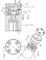
- FIG. 2 is a hollow shaft coupling 1 according to the invention in isolation and thus shown in the non-installed state to explain the hollow shaft coupling 1 better.
- the hollow shaft coupling 1 has a first clamping set 5 and a second clamping set 6.
- the first clamping set 5 has a clamping bush 12 with a cylindrical outer circumferential surface 9 and a central, approximately cylindrical cavity 14.
- this cavity 14 is not strictly cylindrical but tapers conically from axially outside to axially inside.
- an inner cone 15 is inserted, which has a conical outer circumferential surface 16 which is configured conically complementary to the inner circumferential surface 17 of the clamping bush 12.
- the inner cone 15 has a central cylindrical inner cavity 18 into which the shaft 3 protrudes.
- Axially inside the first clamping set 5 is equipped with an inwardly projecting annular shoulder 19, which defines a passage opening 20 through which a threaded Allen screw 21 extends.
- the threaded head 22 with the Allen is supported by the annular shoulder 19.
- the Allen screw 21 protrudes into a central threaded bore 23 in the axially inner end of the inner cone 15 and acts together. When turning the Allen screw 21, this inner cone 15 is drawn into the cavity 14. In this case, the conical outer circumferential surface 16 of the inner cone 15 slides on or along the likewise conical inner circumferential surface 17 of the clamping bush 12, wherein the shaft 3 is clamped.
- the first clamping set 5 is axially opposite the second clamping set 6, which has a clamping bush 24 with a cylindrical outer circumferential surface 25 and an inner space 26 with a cone-like cross section.
- a cone 28 is used, the outer circumferential surface 29 tapers conically toward the first clamping set 5 and tapers. In other words, the diameter of the inner space 26 decreases continuously from the axially inner end to the first clamping set 5.
- the cone 28 has a plurality of radially outwardly disposed through holes 31 through which an axially extending threaded Allen screw 30 extends. These threaded Allen screws 30 are supported with their threaded head on the cone 28 and extend into corresponding threaded holes 13 in the coupling 11th When tightening this Allen screw the cone 28 is pulled into the interior 26.
- the conical outer circumferential surface 29 of the cone 28 runs on the complementary conical inner circumferential surface 27 of the clamping bush 24, wherein a bracing or pressing takes place axially outward.
- the outer diameter of the clamping bush 24 in the region of the outer circumferential surface 25 is greater than the outer diameter of the first clamping set 5 and the clamping bush 12. This creates an annular gap 32 between the first clamping set 5 and the surrounding hollow shaft 2, compare also Fig. 1 ,
- the combination of the two clamping sets 5, 6 and the intermediate and connecting these clamping sets coupling is referred to as a hollow shaft coupling in the present invention.
- the coupling only the connecting device or connecting device between the two clamping sets is referred to as the coupling.
- a clutch consists of two clutch hubs for the drive or the output of a coupling element connecting these two clutch hubs.
- the coupling hubs of the coupling 11 according to the invention can be designed separately.
- the respective Clutch hub with the associated clamping set 5 or 6 are rotatably connected.
- these coupling hubs may also be an integral part of the two clamping sets and be formed in the mutually facing ends, as is the case in the coupling of the embodiments shown in the figures.
- clutch 11 is a spring disc clutch.
- the coupling element 10 has a cylindrical body 33 (see Fig. 4 ), which merges at its two axial ends on the one hand on the first clamping set 5 and on the other hand on the second clamping set 6 in these or is integrally formed therewith.
- slots 34 are arranged.
- the slots 34 of a cross-sectional plane are separated from one another by spring washers 35 which are connected to one another or to the first clamping set 5 and the second clamping set 6 via webs 35.
- spring washers 35 Such a spring washer arrangement is in the aforementioned European patent application 0 318 669 A1 described, the content of which is hereby made the subject of the present application.
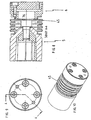
- the in the Fig. 5 to 7 embodiment shown is a plug-in coupling.
- the first clamping set 5 and the second clamping set 6 are the same or similar structure as the corresponding clamping sets in the Fig. 2 to 4 shown embodiment.
- the same or similar elements or parts therefore also have the same reference numerals.
- the first clamping set 5 in the plug-in coupling has at its end pointing to the second clamping set 6 a plurality of axially extending, evenly distributed on the circumference blind holes 37, in each of which a pin 38 is inserted, the over the end of the second clamping set 5 after protrudes axially outside and protrudes into a corresponding through hole 39 in the opposite end of the second clamping set 6.
- a pin 38 acts These are cylindrical pins, which are inserted in the through hole 39 in a lining 40 made of a sliding plastic. In the blind holes 37, the cylindrical pins 38 are inserted accurately.
- Such a structural design or plug-in coupling is in the DE 198 19 239 A1 described, which was also mentioned in the introduction and whose contents are hereby made the subject of the present application.
- the two clamping sets 5 and 6 are connected by means of a metal bellows coupling.
- the coupling element 11 thus has a metal bellows 45 which is fastened at its ends on the one hand to the first clamping set 5 and on the other hand to the second clamping set 6 or firmly connected thereto, for example by gluing.
- the coupling shown is an elastomeric coupling.
- the two clamping sets 5 and 6 also correspond in this embodiment already described in connection with the other embodiments. The difference thus exists primarily in the coupling 11 or in the coupling element 10.
- the first clamping set 5 as well as the second clamping set 6 have at their mutually facing ends axially parallel extending, arranged on the periphery projections 41 and 42, respectively.
- the number of extensions 41 and 42 corresponds to each other.
- the radial distance of the projections 41 is dimensioned such that between two circumferentially adjacent projections 41, an opposite projection 42 and a radially extending tooth 43 of an elastomeric ring gear 44 can come to rest and laterally close to each other, wherein the tooth of elastomeric material is compressed slightly between the two adjacent projections 41 and 42.
- the teeth 43 of this elastomeric ring gear 44 are integrally formed with a ring 45th
Landscapes
- Engineering & Computer Science (AREA)
- General Engineering & Computer Science (AREA)
- Mechanical Engineering (AREA)
- Mutual Connection Of Rods And Tubes (AREA)
- Mechanical Operated Clutches (AREA)
- Shafts, Cranks, Connecting Bars, And Related Bearings (AREA)
Claims (6)
- Accouplement d'arbre creux destiné à relier un arbre (3) à un arbre creux (2), sachant que
cet accouplement d'arbre creux (1) peut être disposé entièrement dans l'arbre creux (2) et peut engendrer un serrage aussi bien vers l'intérieur axialement que vers l'extérieur axialement,
un premier ensemble de serrage (5) serre l'accouplement d'arbre creux (1) contre l'arbre (3) vers l'intérieur axialement,
un deuxième élément de serrage (6) distinct du premier élément de serrage (5) serre l'accouplement d'arbre creux (1) contre la surface d'enveloppe intérieure (7) de l'arbre creux (2) vers l'extérieur axialement et
les deux ensembles de serrage (5, 6) sont axialement écartés l'un de l'autre et sont reliés entre eux sans jeu et de manière solidaire en rotation,
caractérisé en ce que
les deux ensembles de serrage (5, 6) sont reliés par un accouplement (11) disposé entre eux et en ce que l'accouplement (11) est un accouplement enfichable,
un accouplement à soufflet,
un accouplement en élastomère ou
un accouplement à disques élastiques. - Accouplement d'arbre creux selon la revendication 1,
caractérisé en ce que
le diamètre extérieur du deuxième ensemble de serrage (6) est supérieur au diamètre extérieur du premier ensemble de serrage (5). - Accouplement d'arbre creux selon l'une des revendications précédentes,
caractérisé en ce que
l'accouplement (11) présente deux moyeux formés par les éléments de serrage (5, 6) et un élément d'accouplement (10) reliant ces moyeux, un moyen d'actionnement (21) pour le premier ensemble de serrage (5) est accessible par un orifice (36) dans l'élément d'accouplement (10) de l'accouplement (11) depuis le côté de l'accouplement d'arbre creux (1) qui est axialement opposé à l'arbre (3). - Accouplement d'arbre creux selon la revendication 3,
caractérisé en ce que
l'élément d'actionnement (21) est une vis filetée centrée. - Accouplement d'arbre creux selon la revendication 3 ou 4,
caractérisé en ce que
la vis filetée (21) prend dans un alésage fileté (23) d'un cône de serrage de forme conique (15) qui interagit avec une douille de serrage de forme conique (12) pour constituer le premier élément de serrage (5). - Accouplement d'arbre creux selon la revendication 4 ou 5,
caractérisé en ce que
la vis filetée (21) est une vis à six pans creux.
Priority Applications (5)
| Application Number | Priority Date | Filing Date | Title |
|---|---|---|---|
| ES08019852T ES2387830T3 (es) | 2008-11-13 | 2008-11-13 | Acoplamiento de eje hueco |
| EP08019852A EP2187076B1 (fr) | 2008-11-13 | 2008-11-13 | Couplage d'arbre creux |
| US13/129,127 US8727657B2 (en) | 2008-11-13 | 2009-11-12 | Hollow shaft coupling |
| PCT/EP2009/065056 WO2010055095A1 (fr) | 2008-11-13 | 2009-11-12 | Accouplement pour arbre creux |
| US14/255,613 US9624982B2 (en) | 2008-11-13 | 2014-04-17 | Hollow shaft coupling |
Applications Claiming Priority (1)
| Application Number | Priority Date | Filing Date | Title |
|---|---|---|---|
| EP08019852A EP2187076B1 (fr) | 2008-11-13 | 2008-11-13 | Couplage d'arbre creux |
Publications (2)
| Publication Number | Publication Date |
|---|---|
| EP2187076A1 EP2187076A1 (fr) | 2010-05-19 |
| EP2187076B1 true EP2187076B1 (fr) | 2012-07-18 |
Family
ID=40589670
Family Applications (1)
| Application Number | Title | Priority Date | Filing Date |
|---|---|---|---|
| EP08019852A Revoked EP2187076B1 (fr) | 2008-11-13 | 2008-11-13 | Couplage d'arbre creux |
Country Status (4)
| Country | Link |
|---|---|
| US (2) | US8727657B2 (fr) |
| EP (1) | EP2187076B1 (fr) |
| ES (1) | ES2387830T3 (fr) |
| WO (1) | WO2010055095A1 (fr) |
Cited By (1)
| Publication number | Priority date | Publication date | Assignee | Title |
|---|---|---|---|---|
| DE102021101128A1 (de) | 2021-01-20 | 2022-07-21 | Ringfeder Power-Transmission Gmbh | Hohlwellenkupplung |
Families Citing this family (3)
| Publication number | Priority date | Publication date | Assignee | Title |
|---|---|---|---|---|
| EP2187076B1 (fr) * | 2008-11-13 | 2012-07-18 | Ringfeder Power-Transmission GmbH | Couplage d'arbre creux |
| US20130305517A1 (en) * | 2012-05-16 | 2013-11-21 | Laith Anthony Vincent | Captured threaded connector system and method for mechanically coupling components |
| DE102022129232A1 (de) | 2022-11-04 | 2024-05-08 | Wittenstein Se | Spannsatz zum Befestigen einer Hohlwelle eines Getriebes auf einer Motorwelle |
Family Cites Families (25)
| Publication number | Priority date | Publication date | Assignee | Title |
|---|---|---|---|---|
| US355062A (en) * | 1886-12-28 | Joseph s | ||
| US738809A (en) * | 1903-02-12 | 1903-09-15 | John Hutchison | Compression-coupling. |
| US923714A (en) * | 1903-05-28 | 1909-06-01 | George Samuel Searle | Shaft-coupling. |
| US748373A (en) * | 1903-09-08 | 1903-12-29 | Daniel H Hendershot | Shaft-coupling. |
| US2308542A (en) * | 1941-12-06 | 1943-01-19 | Raybould Coupling Company | Coupling |
| DE1853449U (de) * | 1961-04-14 | 1962-06-14 | I C P M Ind Chimiche Porto Mar | Befestigungsvorrichtung mit spreizringen, insbesondere fuer zum aufwickeln von plastikfilmen u. dgl. verwendete rohrfoermige spulkerne. |
| US3191285A (en) * | 1963-02-27 | 1965-06-29 | Metal Bellows Co | Method of making plated construction shaft coupling |
| US3455013A (en) * | 1964-10-28 | 1969-07-15 | Alden G Rayburn | Method of manufacture of flexible couplings |
| GB1402250A (en) * | 1971-05-19 | 1975-08-06 | Hill J A | Coupling members for spools reels or the like |
| DE2610720A1 (de) * | 1976-03-13 | 1977-09-15 | Ringfeder Gmbh | Kraftschluessige, starr wirksame wellenkupplung |
| US4781486A (en) * | 1986-12-03 | 1988-11-01 | Masanori Mochizuki | Shaft coupling |
| DE3887107D1 (de) | 1987-12-01 | 1994-02-24 | Vma Nc Mess Und Antriebstechni | Federscheibenkupplung. |
| DE9003205U1 (fr) * | 1990-03-19 | 1990-06-21 | Ktr Kupplungstechnik Gmbh, 4440 Rheine, De | |
| DE9321116U1 (de) | 1992-08-27 | 1996-03-14 | Kurt Fiedler | Elastische Wellenkupplung |
| DE4228488A1 (de) * | 1992-08-27 | 1994-03-03 | Wolf Woco & Co Franz J | Elastische Wellenkupplung |
| DE4340030C1 (de) | 1993-11-24 | 1995-04-06 | Ief Werner Gmbh | Ausgleichskupplung zum Kuppeln zweier Wellen |
| DE19812223A1 (de) * | 1998-03-19 | 1999-09-23 | Mayr Christian Gmbh & Co Kg | Drehsteife, spielfreie, elastische Metallbalgkupplung zur drehmomentübertragenden Verbindung zweier Wellen |
| DE19819239A1 (de) | 1998-04-29 | 1999-11-04 | Gerd Schuessler | Steckbare Kupplung |
| WO1999058862A1 (fr) * | 1998-05-08 | 1999-11-18 | Varnai Nandor | Dispositif de fabrication d'un joint de tube amovible |
| US7150680B2 (en) * | 1999-05-14 | 2006-12-19 | Precimed S.A. | Drive shaft coupling |
| US6514146B1 (en) * | 2002-02-26 | 2003-02-04 | Kinzou Shinozuka | Low vibration shielded bellows shaft coupling |
| US6969211B2 (en) * | 2002-12-19 | 2005-11-29 | Altman Lee E | Tubular frame structure connector system |
| WO2005036004A1 (fr) * | 2003-10-16 | 2005-04-21 | Technai Team S.R.L. | Transmission avec vis a billes pour axe lineaire |
| EP1923588A1 (fr) | 2006-11-16 | 2008-05-21 | Gerwah GmbH | Soufflet de couplage |
| EP2187076B1 (fr) * | 2008-11-13 | 2012-07-18 | Ringfeder Power-Transmission GmbH | Couplage d'arbre creux |
-
2008
- 2008-11-13 EP EP08019852A patent/EP2187076B1/fr not_active Revoked
- 2008-11-13 ES ES08019852T patent/ES2387830T3/es active Active
-
2009
- 2009-11-12 US US13/129,127 patent/US8727657B2/en not_active Expired - Fee Related
- 2009-11-12 WO PCT/EP2009/065056 patent/WO2010055095A1/fr active Application Filing
-
2014
- 2014-04-17 US US14/255,613 patent/US9624982B2/en not_active Expired - Fee Related
Cited By (3)
| Publication number | Priority date | Publication date | Assignee | Title |
|---|---|---|---|---|
| DE102021101128A1 (de) | 2021-01-20 | 2022-07-21 | Ringfeder Power-Transmission Gmbh | Hohlwellenkupplung |
| WO2022157194A1 (fr) | 2021-01-20 | 2022-07-28 | Ringfeder Power Transmission Gmbh | Accouplement d'arbre creux |
| DE102021101128B4 (de) | 2021-01-20 | 2022-08-18 | Ringfeder Power-Transmission Gmbh | Hohlwellenkupplung |
Also Published As
| Publication number | Publication date |
|---|---|
| EP2187076A1 (fr) | 2010-05-19 |
| US9624982B2 (en) | 2017-04-18 |
| ES2387830T3 (es) | 2012-10-02 |
| US20140227029A1 (en) | 2014-08-14 |
| US20110229259A1 (en) | 2011-09-22 |
| US8727657B2 (en) | 2014-05-20 |
| WO2010055095A1 (fr) | 2010-05-20 |
Similar Documents
| Publication | Publication Date | Title |
|---|---|---|
| EP2176563B1 (fr) | Système de serrage et bague d'éjection et bague conique pour ce système | |
| EP2715201B1 (fr) | Combinaison d'un tuyau flexible en plastique pour appareils de laboratoire et d'un élément à vis | |
| DD284073A5 (de) | Spannsatz | |
| EP0501149A1 (fr) | Serrure pour fixation d'un manchon d'accouplement | |
| EP1790437B1 (fr) | Méthode pour monter en force un moyeu de roue muni d'un palier de roue | |
| EP1995088A2 (fr) | Elément de palier d'insertion, élément de palier d'insertion élastique et dispositif de support de jambe de suspension à ressort | |
| EP2882974B1 (fr) | Élément d'actionnement compensateur d'usure pour embrayage | |
| EP2703661A2 (fr) | Tige de traction-compression | |
| EP2187076B1 (fr) | Couplage d'arbre creux | |
| EP0500746B1 (fr) | Systeme de serrage conique | |
| EP2997286B1 (fr) | Vis d'entraînement à billes | |
| DE3438918C2 (de) | Mitnehmerverbindung zwischen Keilwellen und Keilnaben von Sicherheitslenksäulen | |
| DE19906168C1 (de) | Konusschraubverbindung für Lamellenpaket-Wellenkupplungen | |
| EP1664564B1 (fr) | Systeme pour relier un arbre a une articulation | |
| DE10315534B4 (de) | Spannhülse mit Mutter | |
| EP1865215A1 (fr) | Dispositif de serrage | |
| DE102013201071B3 (de) | Spanneinrichtung | |
| EP2102509B1 (fr) | Tirant et ensemble de modules assemblés par serrage à l'aide dudit tirant | |
| EP1019642B1 (fr) | Articulation pour joints articules appropries a la transmission de couple | |
| DE10245235B4 (de) | Spannsatz | |
| DE102014218432A1 (de) | Spur- oder Lenkstange für ein Fahrzeug | |
| WO2014048989A1 (fr) | Vis de montage destinée à la fixation de ferrures sur des profilés creux, kit de vis de montage et agencement constitué d'un profilé à plusieurs chambres et d'une vis de montage | |
| DE60202282T2 (de) | Klemmspaltmutter | |
| DE4227476C1 (en) | Shaft coupling with two connecting flanges and interposed multi-plate assembly - has specially dimensioned screw bolt shaft cylinder sections associated with centring bushes for play-free support. | |
| EP1843365B1 (fr) | Installation de tige de commutation avec une tige de commutation |
Legal Events
| Date | Code | Title | Description |
|---|---|---|---|
| PUAI | Public reference made under article 153(3) epc to a published international application that has entered the european phase |
Free format text: ORIGINAL CODE: 0009012 |
|
| AK | Designated contracting states |
Kind code of ref document: A1 Designated state(s): AT BE BG CH CY CZ DE DK EE ES FI FR GB GR HR HU IE IS IT LI LT LU LV MC MT NL NO PL PT RO SE SI SK TR |
|
| AX | Request for extension of the european patent |
Extension state: AL BA MK RS |
|
| 17P | Request for examination filed |
Effective date: 20101029 |
|
| 17Q | First examination report despatched |
Effective date: 20101203 |
|
| AKX | Designation fees paid |
Designated state(s): AT BE BG CH CY CZ DE DK EE ES FI FR GB GR HR HU IE IS IT LI LT LU LV MC MT NL NO PL PT RO SE SI SK TR |
|
| RAP1 | Party data changed (applicant data changed or rights of an application transferred) |
Owner name: RINGFEDER POWER-TRANSMISSION GMBH |
|
| GRAP | Despatch of communication of intention to grant a patent |
Free format text: ORIGINAL CODE: EPIDOSNIGR1 |
|
| GRAS | Grant fee paid |
Free format text: ORIGINAL CODE: EPIDOSNIGR3 |
|
| RAP1 | Party data changed (applicant data changed or rights of an application transferred) |
Owner name: RINGFEDER POWER-TRANSMISSION GMBH |
|
| GRAA | (expected) grant |
Free format text: ORIGINAL CODE: 0009210 |
|
| AK | Designated contracting states |
Kind code of ref document: B1 Designated state(s): AT BE BG CH CY CZ DE DK EE ES FI FR GB GR HR HU IE IS IT LI LT LU LV MC MT NL NO PL PT RO SE SI SK TR |
|
| REG | Reference to a national code |
Ref country code: GB Ref legal event code: FG4D Free format text: NOT ENGLISH |
|
| REG | Reference to a national code |
Ref country code: CH Ref legal event code: EP |
|
| RAP2 | Party data changed (patent owner data changed or rights of a patent transferred) |
Owner name: RINGFEDER POWER-TRANSMISSION GMBH |
|
| REG | Reference to a national code |
Ref country code: AT Ref legal event code: REF Ref document number: 567108 Country of ref document: AT Kind code of ref document: T Effective date: 20120815 Ref country code: IE Ref legal event code: FG4D Free format text: LANGUAGE OF EP DOCUMENT: GERMAN |
|
| REG | Reference to a national code |
Ref country code: DE Ref legal event code: R096 Ref document number: 502008007722 Country of ref document: DE Effective date: 20120913 |
|
| REG | Reference to a national code |
Ref country code: ES Ref legal event code: FG2A Ref document number: 2387830 Country of ref document: ES Kind code of ref document: T3 Effective date: 20121002 |
|
| REG | Reference to a national code |
Ref country code: NL Ref legal event code: VDEP Effective date: 20120718 |
|
| REG | Reference to a national code |
Ref country code: LT Ref legal event code: MG4D Effective date: 20120718 |
|
| PG25 | Lapsed in a contracting state [announced via postgrant information from national office to epo] |
Ref country code: CY Free format text: LAPSE BECAUSE OF FAILURE TO SUBMIT A TRANSLATION OF THE DESCRIPTION OR TO PAY THE FEE WITHIN THE PRESCRIBED TIME-LIMIT Effective date: 20120718 Ref country code: IS Free format text: LAPSE BECAUSE OF FAILURE TO SUBMIT A TRANSLATION OF THE DESCRIPTION OR TO PAY THE FEE WITHIN THE PRESCRIBED TIME-LIMIT Effective date: 20121118 Ref country code: HR Free format text: LAPSE BECAUSE OF FAILURE TO SUBMIT A TRANSLATION OF THE DESCRIPTION OR TO PAY THE FEE WITHIN THE PRESCRIBED TIME-LIMIT Effective date: 20120718 Ref country code: FI Free format text: LAPSE BECAUSE OF FAILURE TO SUBMIT A TRANSLATION OF THE DESCRIPTION OR TO PAY THE FEE WITHIN THE PRESCRIBED TIME-LIMIT Effective date: 20120718 Ref country code: LT Free format text: LAPSE BECAUSE OF FAILURE TO SUBMIT A TRANSLATION OF THE DESCRIPTION OR TO PAY THE FEE WITHIN THE PRESCRIBED TIME-LIMIT Effective date: 20120718 Ref country code: NO Free format text: LAPSE BECAUSE OF FAILURE TO SUBMIT A TRANSLATION OF THE DESCRIPTION OR TO PAY THE FEE WITHIN THE PRESCRIBED TIME-LIMIT Effective date: 20121018 |
|
| REG | Reference to a national code |
Ref country code: CH Ref legal event code: NV Representative=s name: TROESCH SCHEIDEGGER WERNER AG, CH |
|
| REG | Reference to a national code |
Ref country code: CH Ref legal event code: NV Representative=s name: TROESCH SCHEIDEGGER WERNER AG, CH |
|
| PG25 | Lapsed in a contracting state [announced via postgrant information from national office to epo] |
Ref country code: GR Free format text: LAPSE BECAUSE OF FAILURE TO SUBMIT A TRANSLATION OF THE DESCRIPTION OR TO PAY THE FEE WITHIN THE PRESCRIBED TIME-LIMIT Effective date: 20121019 Ref country code: SI Free format text: LAPSE BECAUSE OF FAILURE TO SUBMIT A TRANSLATION OF THE DESCRIPTION OR TO PAY THE FEE WITHIN THE PRESCRIBED TIME-LIMIT Effective date: 20120718 Ref country code: LV Free format text: LAPSE BECAUSE OF FAILURE TO SUBMIT A TRANSLATION OF THE DESCRIPTION OR TO PAY THE FEE WITHIN THE PRESCRIBED TIME-LIMIT Effective date: 20120718 Ref country code: PL Free format text: LAPSE BECAUSE OF FAILURE TO SUBMIT A TRANSLATION OF THE DESCRIPTION OR TO PAY THE FEE WITHIN THE PRESCRIBED TIME-LIMIT Effective date: 20120718 Ref country code: PT Free format text: LAPSE BECAUSE OF FAILURE TO SUBMIT A TRANSLATION OF THE DESCRIPTION OR TO PAY THE FEE WITHIN THE PRESCRIBED TIME-LIMIT Effective date: 20121119 Ref country code: SE Free format text: LAPSE BECAUSE OF FAILURE TO SUBMIT A TRANSLATION OF THE DESCRIPTION OR TO PAY THE FEE WITHIN THE PRESCRIBED TIME-LIMIT Effective date: 20120718 |
|
| PG25 | Lapsed in a contracting state [announced via postgrant information from national office to epo] |
Ref country code: NL Free format text: LAPSE BECAUSE OF FAILURE TO SUBMIT A TRANSLATION OF THE DESCRIPTION OR TO PAY THE FEE WITHIN THE PRESCRIBED TIME-LIMIT Effective date: 20120718 |
|
| PLBI | Opposition filed |
Free format text: ORIGINAL CODE: 0009260 |
|
| PG25 | Lapsed in a contracting state [announced via postgrant information from national office to epo] |
Ref country code: RO Free format text: LAPSE BECAUSE OF FAILURE TO SUBMIT A TRANSLATION OF THE DESCRIPTION OR TO PAY THE FEE WITHIN THE PRESCRIBED TIME-LIMIT Effective date: 20120718 Ref country code: CZ Free format text: LAPSE BECAUSE OF FAILURE TO SUBMIT A TRANSLATION OF THE DESCRIPTION OR TO PAY THE FEE WITHIN THE PRESCRIBED TIME-LIMIT Effective date: 20120718 Ref country code: DK Free format text: LAPSE BECAUSE OF FAILURE TO SUBMIT A TRANSLATION OF THE DESCRIPTION OR TO PAY THE FEE WITHIN THE PRESCRIBED TIME-LIMIT Effective date: 20120718 Ref country code: EE Free format text: LAPSE BECAUSE OF FAILURE TO SUBMIT A TRANSLATION OF THE DESCRIPTION OR TO PAY THE FEE WITHIN THE PRESCRIBED TIME-LIMIT Effective date: 20120718 |
|
| 26 | Opposition filed |
Opponent name: R+W ANTRIEBSELEMENTE GMBH Effective date: 20130415 |
|
| PLAX | Notice of opposition and request to file observation + time limit sent |
Free format text: ORIGINAL CODE: EPIDOSNOBS2 |
|
| BERE | Be: lapsed |
Owner name: RINGFEDER POWER-TRANSMISSION G.M.B.H. Effective date: 20121130 |
|
| PG25 | Lapsed in a contracting state [announced via postgrant information from national office to epo] |
Ref country code: SK Free format text: LAPSE BECAUSE OF FAILURE TO SUBMIT A TRANSLATION OF THE DESCRIPTION OR TO PAY THE FEE WITHIN THE PRESCRIBED TIME-LIMIT Effective date: 20120718 |
|
| REG | Reference to a national code |
Ref country code: DE Ref legal event code: R026 Ref document number: 502008007722 Country of ref document: DE Effective date: 20130415 |
|
| PG25 | Lapsed in a contracting state [announced via postgrant information from national office to epo] |
Ref country code: BG Free format text: LAPSE BECAUSE OF FAILURE TO SUBMIT A TRANSLATION OF THE DESCRIPTION OR TO PAY THE FEE WITHIN THE PRESCRIBED TIME-LIMIT Effective date: 20121018 |
|
| REG | Reference to a national code |
Ref country code: IE Ref legal event code: MM4A |
|
| PG25 | Lapsed in a contracting state [announced via postgrant information from national office to epo] |
Ref country code: BE Free format text: LAPSE BECAUSE OF NON-PAYMENT OF DUE FEES Effective date: 20121130 |
|
| PLAF | Information modified related to communication of a notice of opposition and request to file observations + time limit |
Free format text: ORIGINAL CODE: EPIDOSCOBS2 |
|
| PG25 | Lapsed in a contracting state [announced via postgrant information from national office to epo] |
Ref country code: IE Free format text: LAPSE BECAUSE OF NON-PAYMENT OF DUE FEES Effective date: 20121113 |
|
| PG25 | Lapsed in a contracting state [announced via postgrant information from national office to epo] |
Ref country code: MT Free format text: LAPSE BECAUSE OF FAILURE TO SUBMIT A TRANSLATION OF THE DESCRIPTION OR TO PAY THE FEE WITHIN THE PRESCRIBED TIME-LIMIT Effective date: 20120718 |
|
| PLBB | Reply of patent proprietor to notice(s) of opposition received |
Free format text: ORIGINAL CODE: EPIDOSNOBS3 |
|
| PG25 | Lapsed in a contracting state [announced via postgrant information from national office to epo] |
Ref country code: TR Free format text: LAPSE BECAUSE OF FAILURE TO SUBMIT A TRANSLATION OF THE DESCRIPTION OR TO PAY THE FEE WITHIN THE PRESCRIBED TIME-LIMIT Effective date: 20120718 Ref country code: MC Free format text: LAPSE BECAUSE OF NON-PAYMENT OF DUE FEES Effective date: 20121130 |
|
| PG25 | Lapsed in a contracting state [announced via postgrant information from national office to epo] |
Ref country code: HU Free format text: LAPSE BECAUSE OF FAILURE TO SUBMIT A TRANSLATION OF THE DESCRIPTION OR TO PAY THE FEE WITHIN THE PRESCRIBED TIME-LIMIT Effective date: 20081113 |
|
| REG | Reference to a national code |
Ref country code: FR Ref legal event code: PLFP Year of fee payment: 8 |
|
| REG | Reference to a national code |
Ref country code: FR Ref legal event code: PLFP Year of fee payment: 9 |
|
| RDAF | Communication despatched that patent is revoked |
Free format text: ORIGINAL CODE: EPIDOSNREV1 |
|
| STAA | Information on the status of an ep patent application or granted ep patent |
Free format text: STATUS: THE PATENT HAS BEEN GRANTED |
|
| APAH | Appeal reference modified |
Free format text: ORIGINAL CODE: EPIDOSCREFNO |
|
| APBM | Appeal reference recorded |
Free format text: ORIGINAL CODE: EPIDOSNREFNO |
|
| APBP | Date of receipt of notice of appeal recorded |
Free format text: ORIGINAL CODE: EPIDOSNNOA2O |
|
| APBQ | Date of receipt of statement of grounds of appeal recorded |
Free format text: ORIGINAL CODE: EPIDOSNNOA3O |
|
| REG | Reference to a national code |
Ref country code: FR Ref legal event code: PLFP Year of fee payment: 10 |
|
| PGFP | Annual fee paid to national office [announced via postgrant information from national office to epo] |
Ref country code: LU Payment date: 20181129 Year of fee payment: 11 Ref country code: DE Payment date: 20181129 Year of fee payment: 11 Ref country code: AT Payment date: 20181127 Year of fee payment: 11 |
|
| PGFP | Annual fee paid to national office [announced via postgrant information from national office to epo] |
Ref country code: GB Payment date: 20181121 Year of fee payment: 11 Ref country code: ES Payment date: 20181218 Year of fee payment: 11 Ref country code: IT Payment date: 20181122 Year of fee payment: 11 Ref country code: CH Payment date: 20181129 Year of fee payment: 11 Ref country code: FR Payment date: 20181127 Year of fee payment: 11 |
|
| REG | Reference to a national code |
Ref country code: DE Ref legal event code: R119 Ref document number: 502008007722 Country of ref document: DE |
|
| REG | Reference to a national code |
Ref country code: CH Ref legal event code: PL |
|
| REG | Reference to a national code |
Ref country code: DE Ref legal event code: R064 Ref document number: 502008007722 Country of ref document: DE Ref country code: DE Ref legal event code: R103 Ref document number: 502008007722 Country of ref document: DE |
|
| APBU | Appeal procedure closed |
Free format text: ORIGINAL CODE: EPIDOSNNOA9O |
|
| RDAG | Patent revoked |
Free format text: ORIGINAL CODE: 0009271 |
|
| STAA | Information on the status of an ep patent application or granted ep patent |
Free format text: STATUS: PATENT REVOKED |
|
| PG25 | Lapsed in a contracting state [announced via postgrant information from national office to epo] |
Ref country code: LI Free format text: LAPSE BECAUSE OF NON-PAYMENT OF DUE FEES Effective date: 20191130 Ref country code: LU Free format text: LAPSE BECAUSE OF NON-PAYMENT OF DUE FEES Effective date: 20191113 Ref country code: CH Free format text: LAPSE BECAUSE OF NON-PAYMENT OF DUE FEES Effective date: 20191130 |
|
| REG | Reference to a national code |
Ref country code: AT Ref legal event code: MM01 Ref document number: 567108 Country of ref document: AT Kind code of ref document: T Effective date: 20191113 |
|
| REG | Reference to a national code |
Ref country code: FI Ref legal event code: MGE |
|
| 27W | Patent revoked |
Effective date: 20200706 |
|
| GBPR | Gb: patent revoked under art. 102 of the ep convention designating the uk as contracting state |
Effective date: 20200706 |
|
| REG | Reference to a national code |
Ref country code: FI Ref legal event code: MGE |
|
| PG25 | Lapsed in a contracting state [announced via postgrant information from national office to epo] |
Ref country code: DE Free format text: LAPSE BECAUSE OF NON-PAYMENT OF DUE FEES Effective date: 20200603 |
|
| REG | Reference to a national code |
Ref country code: AT Ref legal event code: MA03 Ref document number: 567108 Country of ref document: AT Kind code of ref document: T Effective date: 20200706 |
|
| PG25 | Lapsed in a contracting state [announced via postgrant information from national office to epo] |
Ref country code: FR Free format text: LAPSE BECAUSE OF NON-PAYMENT OF DUE FEES Effective date: 20191130 Ref country code: ES Free format text: LAPSE BECAUSE OF NON-PAYMENT OF DUE FEES Effective date: 20191114 |