EP2187030A1 - Data update processing method and vehicle operation control device - Google Patents
Data update processing method and vehicle operation control device Download PDFInfo
- Publication number
- EP2187030A1 EP2187030A1 EP08827095A EP08827095A EP2187030A1 EP 2187030 A1 EP2187030 A1 EP 2187030A1 EP 08827095 A EP08827095 A EP 08827095A EP 08827095 A EP08827095 A EP 08827095A EP 2187030 A1 EP2187030 A1 EP 2187030A1
- Authority
- EP
- European Patent Office
- Prior art keywords
- value
- processing
- use variable
- maximum value
- maximum
- Prior art date
- Legal status (The legal status is an assumption and is not a legal conclusion. Google has not performed a legal analysis and makes no representation as to the accuracy of the status listed.)
- Granted
Links
Images




Classifications
-
- F—MECHANICAL ENGINEERING; LIGHTING; HEATING; WEAPONS; BLASTING
- F02—COMBUSTION ENGINES; HOT-GAS OR COMBUSTION-PRODUCT ENGINE PLANTS
- F02D—CONTROLLING COMBUSTION ENGINES
- F02D41/00—Electrical control of supply of combustible mixture or its constituents
- F02D41/24—Electrical control of supply of combustible mixture or its constituents characterised by the use of digital means
- F02D41/2406—Electrical control of supply of combustible mixture or its constituents characterised by the use of digital means using essentially read only memories
- F02D41/2425—Particular ways of programming the data
-
- F—MECHANICAL ENGINEERING; LIGHTING; HEATING; WEAPONS; BLASTING
- F02—COMBUSTION ENGINES; HOT-GAS OR COMBUSTION-PRODUCT ENGINE PLANTS
- F02D—CONTROLLING COMBUSTION ENGINES
- F02D41/00—Electrical control of supply of combustible mixture or its constituents
- F02D41/24—Electrical control of supply of combustible mixture or its constituents characterised by the use of digital means
- F02D41/2406—Electrical control of supply of combustible mixture or its constituents characterised by the use of digital means using essentially read only memories
- F02D41/2425—Particular ways of programming the data
- F02D41/2429—Methods of calibrating or learning
- F02D41/2451—Methods of calibrating or learning characterised by what is learned or calibrated
-
- F—MECHANICAL ENGINEERING; LIGHTING; HEATING; WEAPONS; BLASTING
- F02—COMBUSTION ENGINES; HOT-GAS OR COMBUSTION-PRODUCT ENGINE PLANTS
- F02D—CONTROLLING COMBUSTION ENGINES
- F02D41/00—Electrical control of supply of combustible mixture or its constituents
- F02D41/24—Electrical control of supply of combustible mixture or its constituents characterised by the use of digital means
- F02D41/2406—Electrical control of supply of combustible mixture or its constituents characterised by the use of digital means using essentially read only memories
- F02D41/2425—Particular ways of programming the data
- F02D41/2429—Methods of calibrating or learning
- F02D41/2477—Methods of calibrating or learning characterised by the method used for learning
-
- F—MECHANICAL ENGINEERING; LIGHTING; HEATING; WEAPONS; BLASTING
- F02—COMBUSTION ENGINES; HOT-GAS OR COMBUSTION-PRODUCT ENGINE PLANTS
- F02D—CONTROLLING COMBUSTION ENGINES
- F02D41/00—Electrical control of supply of combustible mixture or its constituents
- F02D41/24—Electrical control of supply of combustible mixture or its constituents characterised by the use of digital means
- F02D41/26—Electrical control of supply of combustible mixture or its constituents characterised by the use of digital means using computer, e.g. microprocessor
- F02D41/28—Interface circuits
-
- G—PHYSICS
- G07—CHECKING-DEVICES
- G07C—TIME OR ATTENDANCE REGISTERS; REGISTERING OR INDICATING THE WORKING OF MACHINES; GENERATING RANDOM NUMBERS; VOTING OR LOTTERY APPARATUS; ARRANGEMENTS, SYSTEMS OR APPARATUS FOR CHECKING NOT PROVIDED FOR ELSEWHERE
- G07C5/00—Registering or indicating the working of vehicles
- G07C5/08—Registering or indicating performance data other than driving, working, idle, or waiting time, with or without registering driving, working, idle or waiting time
- G07C5/0841—Registering performance data
- G07C5/085—Registering performance data using electronic data carriers
Definitions
- the present invention pertains to a method of updating maximum or minimum values of measurement data of various types of physical quantities resulting from sensors or the like and particularly relates to shortening processing time and curtailing data quantities required for updating.
- DPF diesel particulate filter
- electronic control devices are configured such that, in regard to the engine coolant temperature, the fuel temperature and the DPF temperature discussed above, judgment processing of whether or not abnormal overheating had occurred in the past at respective temperature measurement places is executed by the electronic control device as one operation analysis. For that reason, electronic control devices are configured such that, in regard to these temperatures, for example, at each predetermined period, a maximum temperature within that period is acquired, the electronic control device compares that maximum temperature with a maximum temperature that has been acquired most recently, and when that maximum temperature exceeds the maximum temperature that has been acquired most recently, that maximum temperature is stored in a nonvolatile storage element or the like as a new maximum temperature, so that when the electronic control device executes operation analysis, those stored data are used in judgment processing.
- the present invention has been made in view of the above-described circumstances and provides a data update processing method that can reliably perform updating of maximum values or minimum values of measurement data with a simple procedure without incurring an increase in the computational load of an arithmetic processing element or an arithmetic processing device such as a microcomputer.
- a data update processing method for updating maximum values of data each time predetermined pieces of data is acquired the maximum value update processing repeats comparing, each time data are acquired, a value of that acquired data and a most recent minimum value and setting the smaller value as a new minimum value, and, each time updating of this minimum value is repeated the predetermined number, comparing the minimum value and the maximum value at that point in time and setting the larger value as a new maximum value, to perform maximum value updating.
- a data update processing method for updating minimum values of data each time predetermined pieces of data is acquired the minimum value update processing repeats comparing, each time data are acquired, a value of that acquired data and a most recent maximum value and setting the larger value as a new maximum value, and, each time updating of this maximum value is repeated the predetermined number, comparing the minimum value at that point in time and the maximum value and setting the smaller value as a new minimum value, to perform minimum value updating.
- a vehicle operation control device equipped with an electronic control unit configured such that it can sequentially update a maximum value of acquired temperature data, store that update value in a nonvolatile storage element, and supply that stored maximum value for operation control of a vehicle as needed, wherein the electronic control unit is configured to compare, each time temperature data are acquired, a value of the acquired temperature data and a minimum value of most recent temperature data and set the smaller value as a new minimum value, and, each time updating of this minimum value is repeated a predetermined number, compare the minimum value at that point in time and the maximum value, set the larger value as a new maximum value and write the new maximum value in the nonvolatile storage element.
- the processing procedure is simple, so the invention achieves the effects that update processing whose reliability is high is reliably performed without increasing the computational load in an arithmetic element and without taking in as update values abnormal data caused by noise or the like, and therefore the invention can contribute to improving the reliability of device operation.
- the device shown in FIG. 1 is one configural example of a vehicle operation control device and in particular generally shows parts relating to engine coolant temperature, fuel temperature and the temperature of a diesel particulate filter (hereinafter called "DPF") to which data update processing of the embodiment of the present invention is applied and whose maximum values are updated.
- DPF diesel particulate filter
- the vehicle operation control device in FIG. 1 is configured to include an electronic control unit (written as "ECU” in FIG. 1 ) 1 and an analog/digital converter (written as "A/D” in FIG. 1 ) 2 that converts output signals of various types of analog sensors and the like into digital signals, and operation control of a vehicle, such as the fuel injection timing of a fuel injection pump 3, is executed by the electronic control unit 1.
- ECU electronice control unit
- A/D analog/digital converter
- the electronic control unit 1 is equipped with a microcomputer (not shown) having, for example, a publicly-known/well-known configuration, volatile storage elements (not shown) such as a RAM and a ROM, and a nonvolatile storage element (written as "EEPROM" in FIG. 1 ) 4 represented by an EEPROM, and the electronic control unit 1 is configured using an input interface circuit (not shown) and an output interface circuit (not shown) as main components.
- a microcomputer not shown having, for example, a publicly-known/well-known configuration
- volatile storage elements such as a RAM and a ROM
- EEPROM nonvolatile storage element
- the output signals of the various types of analog sensors are inputted to the electronic control unit 1 via the analog/digital converter 2 for operation control and failure analysis of the fuel injection pump 3.
- engine coolant temperature, fuel temperature and DPF temperature can be cited as temperatures suited for using a later-discussed data update processing method to perform maximum value updating.
- a coolant temperature sensor 5 that detects the engine coolant temperature, a fuel temperature sensor 6 that detects the fuel temperature and a DPF temperature sensor 7 that detects the temperature of a DPF are shown as representatives of the variously disposed sensors, and output signals of these are inputted via the analog/digital converter 2.
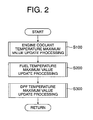
- FIG. 2 there is shown a flowchart showing an overall procedure of data update processing that is executed in the electronic control unit 1, and the procedure of this data update processing will be described below with reference to the same drawing.
- step S100 in FIG. 2 When processing is started, first, update processing of a maximum value of the engine coolant temperature is performed (see step S100 in FIG. 2 ). Then, next, update processing of a maximum value of the fuel temperature is performed (see step S200 in FIG. 2 ), and, next, update processing of a maximum value of the DPF temperature is performed (see step S300 in FIG. 2 ).
- Update processing of all of these maximum values is configured such that later-discussed data update processing is respectively executed and respective maximum values are rewritten at predetermined periods in storage areas respectively ensured within the nonvolatile storage element 4.
- step S300 the flow returns to an unillustrated main routine, and when, for example, failure analysis processing is executed, maximum values are updated by the update processing discussed above such that the maximum values stored in the nonvolatile storage element 4 are adequately used.
- FIG. 3 there is shown a sub-routine flowchart showing a procedure of data update processing of the embodiment of the present invention, and that processing procedure will be described below with reference to the same drawing.
- the data update processing procedure shown in FIG. 3 is particularly for updating maximum values.
- step S402 when processing is started, first, it is determined whether or not initialization has been completed (see step S402 in FIG. 3 ). That is, when the series of processing is started, it is determined whether or not a variable or the like has been set to a predetermined initial value, and when it is determined that initialization has not been completed (in the case of NO), the flow proceeds to the processing of next-discussed step S404, and when it is determined that initialization has been completed (in the case of YES), the flow proceeds to the processing of later-discussed step S406.
- step S404 a maximum value of most recent temperature data stored in the nonvolatile storage element 4 is written to a maximum value-use variable Xmax, a positive maximum value is written to a minimum value-use variable Xmin, and a number-of-times-of-processing-use variable n is initialized to zero.
- the nonvolatile storage element 4 is conveniently written as "EEPROM".
- the maximum value stored in the nonvolatile storage element 4 specifically is the maximum value of the engine coolant temperature that has been stored most recently when the series of processing shown in FIG. 3 is used in the engine coolant temperature maximum value update processing described before (see step S100 in FIG. 2 )
- the maximum value stored in the nonvolatile storage element 4 is the maximum value of the fuel temperature that has been stored most recently when the series of processing shown in FIG. 3 is used in the fuel temperature maximum value update processing (see step S200 in FIG. 2 )
- the maximum value stored in the nonvolatile storage element 4 is the maximum value of the DPF temperature that has been stored most recently when the series of processing shown in FIG. 3 is used in the DPF temperature maximum value update processing (see step S300 in FIG. 2 ).
- step S406 it is determined whether or not a value of the number-of-times-of-processing-use variable n is below a predetermined number of times of processing Ns, and when it is determined that the value of the number-of-times-of-processing-use variable n is below the predetermined number of times of processing Ns (in the case of YES), it is still necessary to continue to execute processing, so a measurement value Xk of the temperature being acquired at this point in time and the value of the minimum value-use variable Xmin are compared, and the smaller value is written to the minimum value-use variable Xmin and is set as a new variable value. Further, at the same time, the sum of "1" and the number-of-times-of-processing-use variable n at this point in time is set as a new value of the number-of-times-of-processing-use variable n.
- the predetermined number of times of processing Ns corresponds to the number of measurement values that are taken in until updating of the maximum value is performed, but it is not necessary for the predetermined number of times of processing Ns to be limited to a particular value; basically, the predetermined number of times of processing Ns can be arbitrarily set, but it is preferable to consider the speed at which the physical quantity that becomes the target of updating changes.
- Ns when temperature data are the target, it is not necessary for the value of the predetermined number of times of processing Ns to be set to that large of a numerical value when the temperature change is relatively gradual, but when temperature data that change from moment to moment within a comparatively short amount of time are the target, it is preferable to set the value of Ns to a relatively large numerical value. It will be noted that whatever value specifically is suitable will variously differ depending on the speed at which the target physical quantity changes, the precision of the update value that is needed, and frequency of updating, so it is preferable to determine the value by experiments and simulations based on those specific numerical values.
- the main routine is any of the engine coolant temperature maximum value update processing (step S 100 in FIG. 2 ), the fuel temperature maximum value update processing (see step S200 in FIG. 2 ) and the DPF temperature maximum value update processing (see step S300 in FIG. 2 ) to which this series of processing is applied.
- step S410 in correspondence to it having been determined that the value of the number-of-times-of-processing-use variable n is not below the predetermined number of times of processing Ns, in order to end the series of update processing, the value of the maximum value-use variable Xmax at this point in time and the value of the minimum value-use variable Xmin are compared and the value whose numerical value is larger is written to the maximum value-use variable Xmax, whereby maximum value updating is performed.
- the new value of the maximum value-use variable Xmax is written in a predetermined area in the nonvolatile storage element 4, the value of the minimum value-use variable Xmin is again set to the minimum value, the number-of-times-of-processing-use variable n is initialized to zero, the series of processing is ended, and the flow returns to the corresponding main routine as mentioned before.
- FIG. 5 there is schematically shown updating of maximum values of temperature data when the predetermined number of times of processing Ns is 5, and maximum value updating in the example shown in the same drawing will be described below.
- the black dots and the double-circle dots respectively represent temperature data that have been acquired, and the numerical values next to those dots represent the order in which the temperature data have been acquired. Further, in the same drawing, the two-dotted chain line represents changes in the update value of the maximum value.
- FIG. 6 in specific numerical value examples, there are shown, in a chart, specific numerical value examples obtained by executing the data update processing shown in FIG. 3 , and these specific examples will be described below with reference to the same drawing and FIG. 3 .
- EEPROM means the nonvolatile storage element 4 and "A/D” means the analog/digital converter 2. Further, “N” means the number of times of processing in total. It will be noted that, in FIG. 6 , "Xmax", Xmin” and “n” are as has been discussed before in the description of FIG. 3 .
- the predetermined number of times of processing Ns described in FIG. 3 is 5.
- the data update processing method discussed above is particularly suited for updating maximum values, but it can also be applied to updating minimum values by basically the same procedure by reversing the relationship between the maximum values and the minimum values in FIG. 3 .
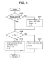
- FIG. 4 there is shown a data update processing procedure suited for updating minimum values, and the minimum value update procedure will be described below with reference to the same drawing. It will be noted that content that is the same as that of the processing procedure shown in FIG. 3 will be appropriately kept to general description and that redundant detailed description will be omitted.
- step S502 in FIG. 4 it is determined whether or not initialization has been completed (see step S502 in FIG. 4 ), and when it is determined that initialization has not been completed (in the case of NO), the flow proceeds to the processing of next-discussed step S504, and when it is determined that initialization has been completed (in the case of YES), the flow proceeds to the processing of later-discussed step S506.
- step S504 a minimum value of the most recent temperature data stored in the nonvolatile storage element 4 is written to the minimum value-use variable Xmin, a negative maximum value is written to the maximum value-use variable Xmax, and the number-of-times-of-processing-use variable n is initialized to zero.
- the nonvolatile storage element 4 is conveniently written as "EEPROM". Further, as for the maximum value stored in the nonvolatile storage element 4, basically the same as what has been described before in S404 in FIG. 3 , there is written a value where a negative sign has been added to the maximum numerical value that can be written in the register (not shown) within the electronic control unit 1 that is used in order to temporarily store the data of the maximum value-use variable Xmax.
- step S506 it is determined whether or not the value of the number-of-times-of-processing-use variable n is below the predetermined number of times of processing Ns, and when it is determined that the value of the number-of-times-of-processing-use variable n is below the predetermined number of times of processing Ns (in the case of YES), it is still necessary to continue to execute updating of the maximum values, so a measurement value Xk of the temperature being acquired at this point in time and the value of the maximum value-use variable Xmax are compared, and the larger value is written to the maximum value-use variable Xmax. Further, at the same time, the sum of "1" and the number-of-times-of-processing-use variable n at this point in time is set as a new value of the number-of-times-of-processing-use variable n.
- the main routine is any of the engine coolant temperature maximum value update processing (step S 100 in FIG. 2 ), the fuel temperature maximum value update processing (see step S200 in FIG. 2 ) and the DPF temperature maximum value update processing (see step S300 in FIG. 2 ) to which this series of processing is applied.
- step S510 in correspondence to it having been determined that the number-of-times-of-processing-use variable n is not below the predetermined number of times of processing Ns, in order to end the series of update processing, the value of the minimum value-use variable Xmin at this point in time and the value of the maximum value-use variable Xmax are compared and the value whose numerical value is smaller is written to the minimum value-use variable Xmin, whereby minimum value updating is performed.
- the new value of the minimum value-use variable Xmin is written in a predetermined area in the nonvolatile storage element 4, a negative maximum value is written to the maximum value-use variable Xmax, the number-of-times-of-processing-use variable n is initialized to zero, the series of processing is ended, and the flow returns to the corresponding main routine as mentioned before.
- the electronic control unit 1 has been described as being configured to be capable of implementing just one of either updating maximum values by the data update processing shown in FIG. 3 or updating minimum values by the data update processing shown in FIG. 4 , but the electronic control unit 1 may also be configured such that it can use a so-called flag to selectively execute either one as desired.
- a processing selection-use flag for selecting updating maximum values or updating minimum values may be disposed, so that the electronic control unit 1 executes maximum value update processing by the data update processing shown in FIG. 3 when the value of that flag is set to "1" and executes minimum value update processing by the data update processing shown in FIG. 4 when the value of that flag is set to "0".
- the invention can execute data update processing while maintaining high reliability without increasing the load in an arithmetic element, so the invention can be applied to vehicle operation control devices and the like where update processing of various types of data is required.
Landscapes
- Engineering & Computer Science (AREA)
- Chemical & Material Sciences (AREA)
- Combustion & Propulsion (AREA)
- Mechanical Engineering (AREA)
- General Engineering & Computer Science (AREA)
- Physics & Mathematics (AREA)
- General Physics & Mathematics (AREA)
- Computer Hardware Design (AREA)
- Microelectronics & Electronic Packaging (AREA)
- Combined Controls Of Internal Combustion Engines (AREA)
Abstract
Description
- The present invention pertains to a method of updating maximum or minimum values of measurement data of various types of physical quantities resulting from sensors or the like and particularly relates to shortening processing time and curtailing data quantities required for updating.
- Conventionally, in operation control of automobiles such as, for example, fuel injection control, measurement values of various types of physical quantities, such as engine coolant temperature, fuel temperature and the temperature of a diesel particulate filter (hereinafter called "DPF"), are directly and indirectly used.
- Incidentally, in automobiles of recent years, electronic control devices for electronically controlling the operation thereof are installed, and there are many electronic control devices configured such that not only operation control for vehicle travel is performed, but also, when some kind of problem arises in the vehicle operation, operation analysis thereof is performed.
- For example, sometimes electronic control devices are configured such that, in regard to the engine coolant temperature, the fuel temperature and the DPF temperature discussed above, judgment processing of whether or not abnormal overheating had occurred in the past at respective temperature measurement places is executed by the electronic control device as one operation analysis. For that reason, electronic control devices are configured such that, in regard to these temperatures, for example, at each predetermined period, a maximum temperature within that period is acquired, the electronic control device compares that maximum temperature with a maximum temperature that has been acquired most recently, and when that maximum temperature exceeds the maximum temperature that has been acquired most recently, that maximum temperature is stored in a nonvolatile storage element or the like as a new maximum temperature, so that when the electronic control device executes operation analysis, those stored data are used in judgment processing.
- When an electronic control device periodically updates and stores this maximum temperature, a situation where abnormal data caused by a temporary problem in the sensor, such as, for example, a temporary disconnection, a short, or noise, are erroneously used as update values must be avoided as much as possible.
- As measures to avoid the acquisition of abnormal data, for example, a technique that uses a so-called mean value of data and a technique that uses a median value of data have conventionally been known (e.g., see
patent document 1, etc.). - Moreover, a technique configured to calculate estimate values of desired physical quantities by arithmetic processing in addition to measurement data and to be able to use those in operation control and the like has been proposed (e.g., see
patent document 2, etc.). - However, in the methods that use a mean value or a median value of measurement values, there are the problems that a large quantity of past data are required, so a large storage area for saving data, or in other words a large-capacity storage element, is required, which not only incurs an increase in the cost of the device but also requires more time for data processing, incurs an increase in the computational load of a microcomputer that performs arithmetic processing, and can affect the processing capability of operation control overall.
- Patent document 1: Japanese Patent No.
2,852,059 - Patent document 2: Japanese Patent No.
3,849,357 - The present invention has been made in view of the above-described circumstances and provides a data update processing method that can reliably perform updating of maximum values or minimum values of measurement data with a simple procedure without incurring an increase in the computational load of an arithmetic processing element or an arithmetic processing device such as a microcomputer.
- It is another object of the present invention to provide a vehicle operation control device that can reliably perform updating of maximum values or minimum values of temperature data with a simple configuration without incurring an increase in the computational load of an arithmetic processing element such as a microcomputer.
- According to a first aspect of the present invention, there is provided a data update processing method for updating maximum values of data each time predetermined pieces of data is acquired, the maximum value update processing repeats comparing, each time data are acquired, a value of that acquired data and a most recent minimum value and setting the smaller value as a new minimum value, and, each time updating of this minimum value is repeated the predetermined number, comparing the minimum value and the maximum value at that point in time and setting the larger value as a new maximum value, to perform maximum value updating.
- According to a second aspect of the present invention, there is provided a data update processing method for updating minimum values of data each time predetermined pieces of data is acquired, the minimum value update processing repeats comparing, each time data are acquired, a value of that acquired data and a most recent maximum value and setting the larger value as a new maximum value, and, each time updating of this maximum value is repeated the predetermined number, comparing the minimum value at that point in time and the maximum value and setting the smaller value as a new minimum value, to perform minimum value updating.
- According to a third aspect of the present invention, there is provided a vehicle operation control device equipped with an electronic control unit configured such that it can sequentially update a maximum value of acquired temperature data, store that update value in a nonvolatile storage element, and supply that stored maximum value for operation control of a vehicle as needed, wherein
the electronic control unit is configured to compare, each time temperature data are acquired, a value of the acquired temperature data and a minimum value of most recent temperature data and set the smaller value as a new minimum value, and, each time updating of this minimum value is repeated a predetermined number, compare the minimum value at that point in time and the maximum value, set the larger value as a new maximum value and write the new maximum value in the nonvolatile storage element. - According to the present invention, the processing procedure is simple, so the invention achieves the effects that update processing whose reliability is high is reliably performed without increasing the computational load in an arithmetic element and without taking in as update values abnormal data caused by noise or the like, and therefore the invention can contribute to improving the reliability of device operation.
-
-
FIG. 1 is a configural diagram showing one configural example of a vehicle operation control device to which a data update processing method of an embodiment of the present invention is applied. -
FIG. 2 is a sub-routine flowchart showing an overall procedure of temperature update processing that is executed in an electronic control unit of the vehicle operation control device shown inFIG. 1 . -
FIG. 3 is a sub-routine flowchart showing a maximum value update procedure resulting from the data update processing of the embodiment of the present invention. -
FIG. 4 is a sub-routine flowchart showing a minimum value update procedure resulting from the data update processing of the embodiment of the present invention. -
FIG. 5 is a schematic diagram schematically showing updating of maximum values resulting from the data update processing of the embodiment of the present invention. -
FIG. 6 is a chart showing specific numerical value examples of updating of maximum values resulting from the data update processing of the embodiment of the present invention. -
- 1
- Electronic Control Unit
- 2
- Analog/Digital Converter
- 3
- Fuel Injection Pump
- 4
- Nonvolatile Storage Element
- 5
- Coolant Temperature Sensor
- 6
- Fuel Temperature Sensor
- 7
- DPF Temperature Sensor
- An embodiment of the present invention will be described below with reference to
FIG. 1 to FIG. 6 . - It will be noted that the members and arrangements described below are not intended to limit the present invention and can be variously modified within the scope of the gist of the present invention.
- First, one configural example of a device to which a maximum value/minimum value update processing method of the embodiment of the present invention is applied will be described with reference to
FIG. 1 . - The device shown in
FIG. 1 is one configural example of a vehicle operation control device and in particular generally shows parts relating to engine coolant temperature, fuel temperature and the temperature of a diesel particulate filter (hereinafter called "DPF") to which data update processing of the embodiment of the present invention is applied and whose maximum values are updated. - That is, the vehicle operation control device in
FIG. 1 is configured to include an electronic control unit (written as "ECU" inFIG. 1 ) 1 and an analog/digital converter (written as "A/D" inFIG. 1 ) 2 that converts output signals of various types of analog sensors and the like into digital signals, and operation control of a vehicle, such as the fuel injection timing of afuel injection pump 3, is executed by theelectronic control unit 1. - The
electronic control unit 1 is equipped with a microcomputer (not shown) having, for example, a publicly-known/well-known configuration, volatile storage elements (not shown) such as a RAM and a ROM, and a nonvolatile storage element (written as "EEPROM" inFIG. 1 ) 4 represented by an EEPROM, and theelectronic control unit 1 is configured using an input interface circuit (not shown) and an output interface circuit (not shown) as main components. - The output signals of the various types of analog sensors are inputted to the
electronic control unit 1 via the analog/digital converter 2 for operation control and failure analysis of thefuel injection pump 3. - In the vehicle operation control device in the configural example of
FIG. 1 , of the variously disposed sensors, engine coolant temperature, fuel temperature and DPF temperature can be cited as temperatures suited for using a later-discussed data update processing method to perform maximum value updating. Additionally, in the configural example ofFIG. 1 , acoolant temperature sensor 5 that detects the engine coolant temperature, afuel temperature sensor 6 that detects the fuel temperature and aDPF temperature sensor 7 that detects the temperature of a DPF (not shown) are shown as representatives of the variously disposed sensors, and output signals of these are inputted via the analog/digital converter 2. - In
FIG. 2 , there is shown a flowchart showing an overall procedure of data update processing that is executed in theelectronic control unit 1, and the procedure of this data update processing will be described below with reference to the same drawing. - When processing is started, first, update processing of a maximum value of the engine coolant temperature is performed (see step S100 in
FIG. 2 ). Then, next, update processing of a maximum value of the fuel temperature is performed (see step S200 inFIG. 2 ), and, next, update processing of a maximum value of the DPF temperature is performed (see step S300 inFIG. 2 ). - It will be noted that the order in which each of the aforementioned temperatures is updated is only one example and is naturally not limited to the order discussed above.
- Update processing of all of these maximum values is configured such that later-discussed data update processing is respectively executed and respective maximum values are rewritten at predetermined periods in storage areas respectively ensured within the
nonvolatile storage element 4. - It will be noted that, after the processing of step S300, the flow returns to an unillustrated main routine, and when, for example, failure analysis processing is executed, maximum values are updated by the update processing discussed above such that the maximum values stored in the
nonvolatile storage element 4 are adequately used. - In
FIG. 3 , there is shown a sub-routine flowchart showing a procedure of data update processing of the embodiment of the present invention, and that processing procedure will be described below with reference to the same drawing. - The data update processing procedure shown in
FIG. 3 is particularly for updating maximum values. - To describe this specifically below, when processing is started, first, it is determined whether or not initialization has been completed (see step S402 in
FIG. 3 ). That is, when the series of processing is started, it is determined whether or not a variable or the like has been set to a predetermined initial value, and when it is determined that initialization has not been completed (in the case of NO), the flow proceeds to the processing of next-discussed step S404, and when it is determined that initialization has been completed (in the case of YES), the flow proceeds to the processing of later-discussed step S406. - In step S404, a maximum value of most recent temperature data stored in the
nonvolatile storage element 4 is written to a maximum value-use variable Xmax, a positive maximum value is written to a minimum value-use variable Xmin, and a number-of-times-of-processing-use variable n is initialized to zero. - Here, in
FIG. 3 , thenonvolatile storage element 4 is conveniently written as "EEPROM". Further, the maximum value stored in thenonvolatile storage element 4 specifically is the maximum value of the engine coolant temperature that has been stored most recently when the series of processing shown inFIG. 3 is used in the engine coolant temperature maximum value update processing described before (see step S100 inFIG. 2 ), the maximum value stored in thenonvolatile storage element 4 is the maximum value of the fuel temperature that has been stored most recently when the series of processing shown inFIG. 3 is used in the fuel temperature maximum value update processing (see step S200 inFIG. 2 ), and the maximum value stored in thenonvolatile storage element 4 is the maximum value of the DPF temperature that has been stored most recently when the series of processing shown inFIG. 3 is used in the DPF temperature maximum value update processing (see step S300 inFIG. 2 ). - Further, in step S404, a positive infinity is written as the positive maximum value to the minimum value-use variable Xmin, but in actuality, a maximum numerical value that is written in a register (not shown) within the
electronic control unit 1 that is used in order to temporarily store data of the minimum value-use variable Xmin is written. That is, assuming that the register has a total 8-bit capacity, the writable maximum numerical value becomes 28-1=255. - Next, in step S406, it is determined whether or not a value of the number-of-times-of-processing-use variable n is below a predetermined number of times of processing Ns, and when it is determined that the value of the number-of-times-of-processing-use variable n is below the predetermined number of times of processing Ns (in the case of YES), it is still necessary to continue to execute processing, so a measurement value Xk of the temperature being acquired at this point in time and the value of the minimum value-use variable Xmin are compared, and the smaller value is written to the minimum value-use variable Xmin and is set as a new variable value. Further, at the same time, the sum of "1" and the number-of-times-of-processing-use variable n at this point in time is set as a new value of the number-of-times-of-processing-use variable n.
- Here, the predetermined number of times of processing Ns corresponds to the number of measurement values that are taken in until updating of the maximum value is performed, but it is not necessary for the predetermined number of times of processing Ns to be limited to a particular value; basically, the predetermined number of times of processing Ns can be arbitrarily set, but it is preferable to consider the speed at which the physical quantity that becomes the target of updating changes.
- That is, for example, when temperature data are the target, it is not necessary for the value of the predetermined number of times of processing Ns to be set to that large of a numerical value when the temperature change is relatively gradual, but when temperature data that change from moment to moment within a comparatively short amount of time are the target, it is preferable to set the value of Ns to a relatively large numerical value. It will be noted that whatever value specifically is suitable will variously differ depending on the speed at which the target physical quantity changes, the precision of the update value that is needed, and frequency of updating, so it is preferable to determine the value by experiments and simulations based on those specific numerical values.
- After the processing of step S408, the flow returns to the main routine and, after other necessary processing, the series of processing discussed above is again repeated. It will be noted that, in the embodiment of the present invention, the main routine is any of the engine coolant temperature maximum value update processing (step S 100 in
FIG. 2 ), the fuel temperature maximum value update processing (see step S200 inFIG. 2 ) and the DPF temperature maximum value update processing (see step S300 inFIG. 2 ) to which this series of processing is applied. - In step S410, in correspondence to it having been determined that the value of the number-of-times-of-processing-use variable n is not below the predetermined number of times of processing Ns, in order to end the series of update processing, the value of the maximum value-use variable Xmax at this point in time and the value of the minimum value-use variable Xmin are compared and the value whose numerical value is larger is written to the maximum value-use variable Xmax, whereby maximum value updating is performed. Further, at the same time, the new value of the maximum value-use variable Xmax is written in a predetermined area in the
nonvolatile storage element 4, the value of the minimum value-use variable Xmin is again set to the minimum value, the number-of-times-of-processing-use variable n is initialized to zero, the series of processing is ended, and the flow returns to the corresponding main routine as mentioned before. - In
FIG. 5 , there is schematically shown updating of maximum values of temperature data when the predetermined number of times of processing Ns is 5, and maximum value updating in the example shown in the same drawing will be described below. - First, in
FIG. 5 , the black dots and the double-circle dots respectively represent temperature data that have been acquired, and the numerical values next to those dots represent the order in which the temperature data have been acquired. Further, in the same drawing, the two-dotted chain line represents changes in the update value of the maximum value. - Under this presupposition, first, in section sec=0 in the same drawing, the temperature data represented by the double-circle dot to which "4" has been added is a minimum value in that section and is set as a maximum value of the temperature data at the point in time when this section sec=0 ends (see the two-dotted chain line in
FIG. 5 ). It will be noted that, in this case, when executing step S410 inFIG. 3 , it is presupposed that the value of the maximum value-use variable Xmax or in other words the value that is written to Xmax from thenonvolatile storage element 4 in step S404, is small in comparison to the value of the temperature at the dot to which "4" has been added in section sec=0. - Next, in section sec=1, the temperature data represented by the double-circle dot to which "3" has been added is a minimum value in that section and is set as a maximum value of the temperature data at the point in time when this section sec=1 ends (see the two-dotted chain line in
FIG. 5 ). - Thereafter, in the same manner, the minimum value of the temperature data in each section of sec=2 to sec=4 is set as the maximum value of the temperature data, whereby maximum value updating is performed.
- In this manner, by performing maximum value data updating on the basis of the data update processing method of the embodiment of the present invention, a situation where abnormal values that stand out such as indicated by the white arrows in
FIG. 5 and whose cause may be considered to be noise or the like are updated as maximum values becomes reliably prevented. - In
FIG. 6 , in specific numerical value examples, there are shown, in a chart, specific numerical value examples obtained by executing the data update processing shown inFIG. 3 , and these specific examples will be described below with reference to the same drawing andFIG. 3 . - First, in
FIG. 6 , "EEPROM" means thenonvolatile storage element 4 and "A/D" means the analog/digital converter 2. Further, "N" means the number of times of processing in total. It will be noted that, inFIG. 6 , "Xmax", Xmin" and "n" are as has been discussed before in the description ofFIG. 3 . - Further, in the case of this example, the predetermined number of times of processing Ns described in
FIG. 3 is 5. - Additionally, it will be assumed that a
maximum value 30 is stored and saved in thenonvolatile storage element 4 at the point in time when processing starts. - Under this presupposition, when processing is started, the "30" that is stored and saved in the
nonvolatile storage element 4 is written to the maximum value-use variable Xmax, a positive maximum value is written to the minimum value-use variable Xmin, and 0 is written to the number-of-times-of-processing-use variable n (see step S404 inFIG. 3 and column N=1 inFIG. 6 ). - Next, at the point in time when N=2, for example, "10" is inputted as a measurement value Xk to the
electronic control unit 1 via the analog/digital converter 2 as the engine cooling water value temperature detected by thecoolant temperature sensor 5. At this point in time, n is less than Ns (see step S406 inFIG. 3 ), so the smaller value of Xmin=∞ and Xk=10, that is, "10", is written to the minimum value-use variable Xmin, and n is increased by 1 such that n=1 (see column N=2 inFIG. 6 ). - Next, at the point in time when N=3, assuming that Xk=20 has been inputted, n is still less than Ns (see step S406 in
FIG. 3 ), so the smaller value of Xmin=10 and Xk=20 is selected as Xmin, and, as a result, in this case Xmin=10 is maintained as is. - Next, at the point in time when N=4, assuming that Xk=100 has been inputted, n is still less than Ns (see step S406 in
FIG. 3 ), so the smaller value of Xmin=10 and Xk=100 is selected as Xmin, and, as a result, Xmin=10 is maintained as is in the same manner as previously. - Moreover, at the point in time when N=5, assuming that Xk=40 has been inputted, n is still less than Ns (see step S406 in
FIG. 3 ), so Xmin=10 is, as the smaller value of Xmin=10 and Xk=40, maintained as is in the same manner as previously. - Then, at the point in time when N=6, n<Ns is not established, so Xmax=30 and Xmin=10 are compared, the larger value of these, that is, "30", is written anew as Xmax in the
nonvolatile storage element 4, Xmin=∞ is set and n=0 is set (see step S410 inFIG. 3 ). - Then, the same processing is again repeated (see column N=7 to 11 in
FIG. 6 ). In this example, in section N=7 to 11, the maximum value of the measurement values Xk is 50 and Xmax=30, so when these sections end, "50" is selected as the value of Xmax and is written in thenonvolatile storage element 4 as a new value of Xmax by the processing of step S410 shown inFIG. 3 . - Next, in section N=12 to 16, the processing shown in
FIG. 3 is repeatedly performed. In this section, a negative value "-100" is inputted just once as Xk (see column N=14 inFIG. 6 ). - Then, when this section ends, the processing of step S410 shown in
FIG. 3 is executed, whereby the larger value of Xmax=50 and Xmin=-100, that is, "50", is selected and is written anew as the value of Xmax in the nonvolatile storage element 4 (see column N=16 inFIG. 6 ). - In this manner, in the data update processing method of the embodiment of the present invention, regardless of whether the data are positive or negative, even when abnormal values of the measurement values Xk such as at N=4 and N=14 in
FIG. 6 , for example, caused by noise or the like, for example, occur, a situation where these abnormal values are updated as maximum values can be reliably prevented. - The data update processing method discussed above is particularly suited for updating maximum values, but it can also be applied to updating minimum values by basically the same procedure by reversing the relationship between the maximum values and the minimum values in
FIG. 3 . - In
FIG. 4 , there is shown a data update processing procedure suited for updating minimum values, and the minimum value update procedure will be described below with reference to the same drawing. It will be noted that content that is the same as that of the processing procedure shown inFIG. 3 will be appropriately kept to general description and that redundant detailed description will be omitted. - First, it is determined whether or not initialization has been completed (see step S502 in
FIG. 4 ), and when it is determined that initialization has not been completed (in the case of NO), the flow proceeds to the processing of next-discussed step S504, and when it is determined that initialization has been completed (in the case of YES), the flow proceeds to the processing of later-discussed step S506. - It will be noted that this initialization is as has been described in step S402 in
FIG. 3 , so redundant detailed description here will be omitted. - In step S504, a minimum value of the most recent temperature data stored in the
nonvolatile storage element 4 is written to the minimum value-use variable Xmin, a negative maximum value is written to the maximum value-use variable Xmax, and the number-of-times-of-processing-use variable n is initialized to zero. - Here, in
FIG. 4 , thenonvolatile storage element 4 is conveniently written as "EEPROM". Further, as for the maximum value stored in thenonvolatile storage element 4, basically the same as what has been described before in S404 inFIG. 3 , there is written a value where a negative sign has been added to the maximum numerical value that can be written in the register (not shown) within theelectronic control unit 1 that is used in order to temporarily store the data of the maximum value-use variable Xmax. - Next, in step S506, it is determined whether or not the value of the number-of-times-of-processing-use variable n is below the predetermined number of times of processing Ns, and when it is determined that the value of the number-of-times-of-processing-use variable n is below the predetermined number of times of processing Ns (in the case of YES), it is still necessary to continue to execute updating of the maximum values, so a measurement value Xk of the temperature being acquired at this point in time and the value of the maximum value-use variable Xmax are compared, and the larger value is written to the maximum value-use variable Xmax. Further, at the same time, the sum of "1" and the number-of-times-of-processing-use variable n at this point in time is set as a new value of the number-of-times-of-processing-use variable n.
- After the processing of step S508, the flow returns to the main routine and, after other necessary processing, the aforementioned series of processing is again repeated. It will be noted that, in the embodiment of the present invention, the main routine is any of the engine coolant temperature maximum value update processing (step S 100 in
FIG. 2 ), the fuel temperature maximum value update processing (see step S200 inFIG. 2 ) and the DPF temperature maximum value update processing (see step S300 inFIG. 2 ) to which this series of processing is applied. - In step S510, in correspondence to it having been determined that the number-of-times-of-processing-use variable n is not below the predetermined number of times of processing Ns, in order to end the series of update processing, the value of the minimum value-use variable Xmin at this point in time and the value of the maximum value-use variable Xmax are compared and the value whose numerical value is smaller is written to the minimum value-use variable Xmin, whereby minimum value updating is performed. Further, at the same time, the new value of the minimum value-use variable Xmin is written in a predetermined area in the
nonvolatile storage element 4, a negative maximum value is written to the maximum value-use variable Xmax, the number-of-times-of-processing-use variable n is initialized to zero, the series of processing is ended, and the flow returns to the corresponding main routine as mentioned before. - It will be noted that, in the embodiment discussed above, the
electronic control unit 1 has been described as being configured to be capable of implementing just one of either updating maximum values by the data update processing shown inFIG. 3 or updating minimum values by the data update processing shown inFIG. 4 , but theelectronic control unit 1 may also be configured such that it can use a so-called flag to selectively execute either one as desired. - That is, for example, a processing selection-use flag for selecting updating maximum values or updating minimum values may be disposed, so that the
electronic control unit 1 executes maximum value update processing by the data update processing shown inFIG. 3 when the value of that flag is set to "1" and executes minimum value update processing by the data update processing shown inFIG. 4 when the value of that flag is set to "0". - The invention can execute data update processing while maintaining high reliability without increasing the load in an arithmetic element, so the invention can be applied to vehicle operation control devices and the like where update processing of various types of data is required.
Claims (6)
- A data update processing method for updating maximum values of data each time predetermined pieces of data is acquired, the maximum value update processing repeats comparing, each time data are acquired, a value of that acquired data and a most recent minimum value and setting the smaller value as a new minimum value, and, each time updating of this minimum value is repeated the predetermined number, comparing the minimum value and the maximum value at that point in time and setting the larger value as a new maximum value, to perform maximum value updating.
- A data update processing method for updating minimum values of data each time predetermined pieces of data is acquired, the minimum value update processing repeats comparing, each time data are acquired, a value of that acquired data and a most recent maximum value and setting the larger value as a new maximum value, and, each time updating of this maximum value is repeated the predetermined number, comparing the minimum value and the maximum value at that point in time and setting the smaller value as a new minimum value, to perform minimum value updating.
- A data update processing method that performs updating of minimum values or maximum values of data, wherein
the method enables selection of either updating of maximum values or updating of minimum values depending on a numerical value that has been set in a processing selection-use flag,
the method performs maximum value update processing when updating of maximum values has been selected by the processing selection-use flag and performs minimum value update processing when updating of minimum values has been selected by the processing selection-use flag,
the maximum value update processing repeats comparing, each time data are acquired, a value of that acquired data and a most recent minimum value and setting the smaller value as a new minimum value, and, each time updating of this minimum value is repeated the predetermined number, comparing the minimum value and the maximum value at that point in time and setting the larger value as a new maximum value, to thereby perform maximum value updating, and
the minimum value update processing repeats comparing, each time data are acquired, a value of that acquired data and a most recent maximum value and setting the larger value as a new maximum value, and, each time updating of this maximum value is repeated the predetermined number, comparing the minimum value and the maximum value at that point in time and setting the smaller value as a new minimum value, to thereby perform minimum value updating. - A data update processing program that is executed in an electronic control unit configured such that it can sequentially update a maximum value of acquired data, store that update value in a nonvolatile storage element and supply that stored maximum value for operation control as needed, the program comprising the steps of:determining whether or not initialization has been completed;when, in the step of determining whether or not initialization has been completed, it has been determined that initialization has not been completed, writing the maximum value stored in the nonvolatile storage element to a maximum value-use variable, writing a predetermined positive maximum value to a minimum value-use variable and initializing a number-of-times-of-processing-use variable to zero;when, in the step of determining whether or not initialization has been completed, it has been determined that initialization has been completed, determining whether or not a value of the number-of-times-of-processing-use variable is below a predetermined number of times of processing;when, in the step of determining the value of the number-of-times-of-processing-use variable, it has been determined that the value of the number-of-times-of-processing-use variable is below the predetermined number of times of processing, comparing the value of the acquired data at that point in time and the value of the minimum value-use variable, setting the smaller value as a new value of the minimum value-use variable, and incrementing the value of the number-of-times-of-processing-use variable by 1; andwhen, in the step of determining the value of the number-of-times-of-processing use variable, it has been determined that the value of the number-of-times-of-processing-use variable is not below the predetermined number of times of processing, comparing the value of the maximum value-use variable at that point in time and the value of the minimum value-use variable, setting the larger value as a new value of the maximum value-use variable, writing the value of that maximum value-use variable in the nonvolatile storage element, writing a predetermined positive maximum value to the minimum value-use variable, and initializing the number-of-times-of-processing-use variable to zero,wherein the program repeatedly executes each step until, in the step of determining whether or not the value of the number-of-times-of-processing-use variable is below the predetermined number of times of processing, it has been determined at least once that the value of the number-of-times-of-processing-use variable is not below the predetermined number of times of processing, whereby the program enables updating of maximum values.
- A data update processing program that is executed in an electronic control unit configured such that it can sequentially update a minimum value of acquired data, store that update value in a nonvolatile storage element and supply that stored minimum value for operation control as needed, the program comprising the steps of:determining whether or not initialization has been completed;when, in the step of determining whether or not initialization has been completed, it has been determined that initialization has not been completed, writing the minimum value stored in the nonvolatile storage element to a minimum value-use variable, writing a predetermined negative maximum value to a maximum value-use variable and initializing a number-of-times-of-processing-use variable to zero;when, in the step of determining whether or not initialization has been completed, it has been determined that initialization has been completed, determining whether or not a value of the number-of-times-of-processing-use variable is below a predetermined number of times of processing;when, in the step of determining the value of the number-of-times-of-processing-use variable, it has been determined that the value of the number-of-times-of-processing-use variable is below the predetermined number of times of processing, comparing the value of the acquired data at that point in time and the value of the maximum value-use variable, setting the larger value as a new value of the maximum value-use variable, and incrementing the value of the number-of-times-of-processing-use variable by 1; andwhen, in the step of determining the value of the number-of-times-of-processing use variable, it has been determined that the value of the number-of-times-of-processing-use variable is not below the predetermined number of times of processing, comparing the value of the maximum value-use variable at that point in time and the value of the minimum value-use variable, setting the smaller value as a new value of the minimum value-use variable, writing the value of that minimum value-use variable in the nonvolatile storage element, writing a predetermined negative maximum value to the maximum value-use variable, and initializing the number-of-times-of-processing-use variable to zero,wherein the program repeatedly executes each step until, in the step of determining whether or not the value of the number-of-times-of-processing-use variable is below the predetermined number of times of processing, it has been determined at least once that the value of the number-of-times-of-processing-use variable is not below the predetermined number of times of processing, whereby the program enables updating of minimum values.
- A vehicle operation control device equipped with an electronic control unit configured such that it can sequentially update a maximum value of acquired temperature data, store that update value in a nonvolatile storage element, and supply that stored maximum value for operation control of a vehicle as needed, wherein
the electronic control unit is configured to compare, each time temperature data are acquired, a value of the acquired temperature data and a minimum value of most recent temperature data and set the smaller value as a new minimum value, and, each time updating of this minimum value is repeated a predetermined number, compare the minimum value at that point in time and the maximum value, set the larger value as a new maximum value and write the new maximum value in the nonvolatile storage element.
Applications Claiming Priority (2)
| Application Number | Priority Date | Filing Date | Title |
|---|---|---|---|
| JP2007207542A JP5007176B2 (en) | 2007-08-09 | 2007-08-09 | Data update processing method and vehicle motion control device |
| PCT/JP2008/064115 WO2009020149A1 (en) | 2007-08-09 | 2008-08-06 | Data update processing method and vehicle operation control device |
Publications (4)
| Publication Number | Publication Date |
|---|---|
| EP2187030A1 true EP2187030A1 (en) | 2010-05-19 |
| EP2187030A4 EP2187030A4 (en) | 2012-04-04 |
| EP2187030B1 EP2187030B1 (en) | 2013-05-29 |
| EP2187030B9 EP2187030B9 (en) | 2013-09-04 |
Family
ID=40341381
Family Applications (1)
| Application Number | Title | Priority Date | Filing Date |
|---|---|---|---|
| EP08827095.4A Active EP2187030B9 (en) | 2007-08-09 | 2008-08-06 | Data update processing method and vehicle operation control device |
Country Status (5)
| Country | Link |
|---|---|
| US (1) | US8260484B2 (en) |
| EP (1) | EP2187030B9 (en) |
| JP (1) | JP5007176B2 (en) |
| CN (1) | CN101779030B (en) |
| WO (1) | WO2009020149A1 (en) |
Families Citing this family (3)
| Publication number | Priority date | Publication date | Assignee | Title |
|---|---|---|---|---|
| CN103714591B (en) * | 2012-10-08 | 2016-06-29 | 中国北车股份有限公司 | Rail vehicle operation data storage method and data recording equipment |
| US9847359B2 (en) * | 2015-11-17 | 2017-12-19 | Semiconductor Components Industries, Llc | Image sensors with improved surface planarity |
| JP6798227B2 (en) * | 2016-10-03 | 2020-12-09 | オムロン株式会社 | Control device, control method of control device, control program, and recording medium |
Family Cites Families (21)
| Publication number | Priority date | Publication date | Assignee | Title |
|---|---|---|---|---|
| JPS5864549A (en) * | 1981-10-13 | 1983-04-16 | Fujitsu Ltd | Selecting circuit |
| DE3643450A1 (en) * | 1986-12-19 | 1988-06-30 | Diehl Gmbh & Co | Circuit arrangement for determining an extreme value |
| JP2852059B2 (en) | 1989-01-20 | 1999-01-27 | 富士重工業株式会社 | Analog / digital converter for vehicle control |
| US5214580A (en) * | 1990-06-27 | 1993-05-25 | Hewlett-Packard Company | Process for identifying discrete data representative of an input sample stream |
| DE4307366C2 (en) * | 1993-03-09 | 1996-10-24 | Hagenuk Kmt Kabelmestechnik Gm | Adaptation device |
| JPH09266499A (en) * | 1996-01-26 | 1997-10-07 | Oki Electric Ind Co Ltd | Digital demodulating circuit, maximum detecting circuit, and reception device |
| JP3849357B2 (en) | 1999-07-02 | 2006-11-22 | 三菱自動車工業株式会社 | Catalyst temperature estimation device |
| DE10004080C1 (en) * | 2000-01-31 | 2001-09-06 | Infineon Technologies Ag | Sensor device and method for generating an output signal of a sensor device |
| DE10043695A1 (en) * | 2000-09-04 | 2002-03-14 | Bosch Gmbh Robert | Method for determining a hot start situation in an internal combustion engine |
| JP2002323409A (en) * | 2001-04-26 | 2002-11-08 | Fuji Heavy Ind Ltd | Vehicle management system |
| JP3783845B2 (en) * | 2001-05-09 | 2006-06-07 | 三菱電機株式会社 | In-vehicle electronic control unit |
| JP4139613B2 (en) * | 2002-03-18 | 2008-08-27 | 株式会社日立製作所 | Data processing method |
| US7117209B2 (en) * | 2003-03-28 | 2006-10-03 | International Business Machines Corporation | Record trimming method, apparatus, and system to improve processing in a sort utility |
| JP2005038022A (en) * | 2003-07-15 | 2005-02-10 | Natl Inst For Land & Infrastructure Management Mlit | 2-wire measurement and processing system |
| JP4281610B2 (en) * | 2004-04-27 | 2009-06-17 | 株式会社豊田自動織機 | Operation method of premixed compression self-ignition engine and premixed compression self-ignition engine |
| JP4395736B2 (en) * | 2004-06-03 | 2010-01-13 | 株式会社豊田自動織機 | Exhaust gas purification device management device and exhaust gas purification device management system |
| JP2007047095A (en) * | 2005-08-12 | 2007-02-22 | Hioki Ee Corp | Data processing circuit, data processing method, and waveform display device |
| JP4600369B2 (en) * | 2006-09-05 | 2010-12-15 | 株式会社デンソー | Pressure reducing valve delay compensation device and program |
| CN101285426B (en) * | 2007-04-09 | 2010-10-06 | 山东申普汽车控制技术有限公司 | Method for combined pulse spectrum controlling engine idle speed |
| JP4525729B2 (en) * | 2007-10-26 | 2010-08-18 | 株式会社デンソー | EGR distribution variation detection device |
| JP4462327B2 (en) * | 2007-10-26 | 2010-05-12 | 株式会社デンソー | Cylinder characteristic variation detector |
-
2007
- 2007-08-09 JP JP2007207542A patent/JP5007176B2/en active Active
-
2008
- 2008-08-06 WO PCT/JP2008/064115 patent/WO2009020149A1/en not_active Ceased
- 2008-08-06 EP EP08827095.4A patent/EP2187030B9/en active Active
- 2008-08-06 CN CN2008801027112A patent/CN101779030B/en active Active
- 2008-08-06 US US12/672,184 patent/US8260484B2/en active Active
Also Published As
| Publication number | Publication date |
|---|---|
| JP5007176B2 (en) | 2012-08-22 |
| WO2009020149A1 (en) | 2009-02-12 |
| EP2187030B1 (en) | 2013-05-29 |
| JP2009041455A (en) | 2009-02-26 |
| US8260484B2 (en) | 2012-09-04 |
| US20110224867A1 (en) | 2011-09-15 |
| EP2187030A4 (en) | 2012-04-04 |
| CN101779030B (en) | 2013-11-13 |
| EP2187030B9 (en) | 2013-09-04 |
| CN101779030A (en) | 2010-07-14 |
Similar Documents
| Publication | Publication Date | Title |
|---|---|---|
| US8090494B2 (en) | Electronic apparatus and program storage medium | |
| US7194392B2 (en) | System for estimating model parameters | |
| CN112161663B (en) | Vehicle residual oil amount determining method, device, equipment and vehicle | |
| JP6125111B2 (en) | In-vehicle electronic control unit | |
| US20040034504A1 (en) | Method and control unit for determining the probability of failure of a motor-vehicle component | |
| KR101356284B1 (en) | Method for the determination of rail pressure nominal value | |
| EP2187030A1 (en) | Data update processing method and vehicle operation control device | |
| CN113454554B (en) | Method and device for predictive maintenance of road vehicle components | |
| EP2993465B1 (en) | Lambda sensor preheating control method and lambda sensor driving control device | |
| EP2083160A1 (en) | Pilot jet control method and device therefor | |
| US8276566B2 (en) | Method for operating a fuel injection system of a motor vehicle in particular | |
| CN110552800B (en) | Throttle valve control method and device | |
| US11067024B2 (en) | Method for requirement-based servicing of an injector | |
| JPH11141391A (en) | Automotive control device | |
| WO2011087429A1 (en) | Method and system for updating of software | |
| JP4158566B2 (en) | Electronic control device having floating point arithmetic function | |
| CN111994082B (en) | Regeneration temperature correction method and device, controller and vehicle | |
| US7628535B2 (en) | Method for ascertaining information about a device exposed to a temperature | |
| EP2045779A1 (en) | Vehicular control apparatus and program storage medium | |
| CN116241352B (en) | Method and device for determining engine oil pressure, vehicle and storage medium | |
| JP5103418B2 (en) | Electronic control device | |
| CN116591816B (en) | Thermostat sticking diagnostic methods, devices, electronic equipment and vehicles | |
| CN117213547A (en) | Automatic correction method and device for sensor null shift | |
| EP3428431B1 (en) | Fuel microinjection volume correction method and common-rail fuel injection control device | |
| DE102022213258A1 (en) | Method and device for determining an oil temperature for a vehicle and transmission arrangement |
Legal Events
| Date | Code | Title | Description |
|---|---|---|---|
| PUAI | Public reference made under article 153(3) epc to a published international application that has entered the european phase |
Free format text: ORIGINAL CODE: 0009012 |
|
| 17P | Request for examination filed |
Effective date: 20100309 |
|
| AK | Designated contracting states |
Kind code of ref document: A1 Designated state(s): AT BE BG CH CY CZ DE DK EE ES FI FR GB GR HR HU IE IS IT LI LT LU LV MC MT NL NO PL PT RO SE SI SK TR |
|
| AX | Request for extension of the european patent |
Extension state: AL BA MK RS |
|
| DAX | Request for extension of the european patent (deleted) | ||
| A4 | Supplementary search report drawn up and despatched |
Effective date: 20120305 |
|
| RIC1 | Information provided on ipc code assigned before grant |
Ipc: F02D 45/00 20060101AFI20120228BHEP Ipc: F02D 41/24 20060101ALI20120228BHEP Ipc: G07C 5/08 20060101ALI20120228BHEP |
|
| REG | Reference to a national code |
Ref country code: DE Ref legal event code: R079 Ref document number: 602008025056 Country of ref document: DE Free format text: PREVIOUS MAIN CLASS: F02D0045000000 Ipc: F02D0043020000 |
|
| RIC1 | Information provided on ipc code assigned before grant |
Ipc: G07C 5/08 20060101ALI20121105BHEP Ipc: F02D 41/28 20060101ALI20121105BHEP Ipc: F02D 43/02 20060101AFI20121105BHEP Ipc: F02D 41/24 20060101ALI20121105BHEP |
|
| GRAP | Despatch of communication of intention to grant a patent |
Free format text: ORIGINAL CODE: EPIDOSNIGR1 |
|
| GRAS | Grant fee paid |
Free format text: ORIGINAL CODE: EPIDOSNIGR3 |
|
| GRAA | (expected) grant |
Free format text: ORIGINAL CODE: 0009210 |
|
| AK | Designated contracting states |
Kind code of ref document: B1 Designated state(s): AT BE BG CH CY CZ DE DK EE ES FI FR GB GR HR HU IE IS IT LI LT LU LV MC MT NL NO PL PT RO SE SI SK TR |
|
| REG | Reference to a national code |
Ref country code: GB Ref legal event code: FG4D |
|
| REG | Reference to a national code |
Ref country code: CH Ref legal event code: EP |
|
| REG | Reference to a national code |
Ref country code: AT Ref legal event code: REF Ref document number: 614562 Country of ref document: AT Kind code of ref document: T Effective date: 20130615 |
|
| REG | Reference to a national code |
Ref country code: IE Ref legal event code: FG4D |
|
| REG | Reference to a national code |
Ref country code: DE Ref legal event code: R096 Ref document number: 602008025056 Country of ref document: DE Effective date: 20130725 |
|
| REG | Reference to a national code |
Ref country code: AT Ref legal event code: MK05 Ref document number: 614562 Country of ref document: AT Kind code of ref document: T Effective date: 20130529 |
|
| REG | Reference to a national code |
Ref country code: LT Ref legal event code: MG4D |
|
| PG25 | Lapsed in a contracting state [announced via postgrant information from national office to epo] |
Ref country code: SE Free format text: LAPSE BECAUSE OF FAILURE TO SUBMIT A TRANSLATION OF THE DESCRIPTION OR TO PAY THE FEE WITHIN THE PRESCRIBED TIME-LIMIT Effective date: 20130529 Ref country code: GR Free format text: LAPSE BECAUSE OF FAILURE TO SUBMIT A TRANSLATION OF THE DESCRIPTION OR TO PAY THE FEE WITHIN THE PRESCRIBED TIME-LIMIT Effective date: 20130830 Ref country code: SI Free format text: LAPSE BECAUSE OF FAILURE TO SUBMIT A TRANSLATION OF THE DESCRIPTION OR TO PAY THE FEE WITHIN THE PRESCRIBED TIME-LIMIT Effective date: 20130529 Ref country code: IS Free format text: LAPSE BECAUSE OF FAILURE TO SUBMIT A TRANSLATION OF THE DESCRIPTION OR TO PAY THE FEE WITHIN THE PRESCRIBED TIME-LIMIT Effective date: 20130929 Ref country code: LT Free format text: LAPSE BECAUSE OF FAILURE TO SUBMIT A TRANSLATION OF THE DESCRIPTION OR TO PAY THE FEE WITHIN THE PRESCRIBED TIME-LIMIT Effective date: 20130529 Ref country code: ES Free format text: LAPSE BECAUSE OF FAILURE TO SUBMIT A TRANSLATION OF THE DESCRIPTION OR TO PAY THE FEE WITHIN THE PRESCRIBED TIME-LIMIT Effective date: 20130909 Ref country code: FI Free format text: LAPSE BECAUSE OF FAILURE TO SUBMIT A TRANSLATION OF THE DESCRIPTION OR TO PAY THE FEE WITHIN THE PRESCRIBED TIME-LIMIT Effective date: 20130529 Ref country code: NO Free format text: LAPSE BECAUSE OF FAILURE TO SUBMIT A TRANSLATION OF THE DESCRIPTION OR TO PAY THE FEE WITHIN THE PRESCRIBED TIME-LIMIT Effective date: 20130829 Ref country code: PT Free format text: LAPSE BECAUSE OF FAILURE TO SUBMIT A TRANSLATION OF THE DESCRIPTION OR TO PAY THE FEE WITHIN THE PRESCRIBED TIME-LIMIT Effective date: 20130930 Ref country code: AT Free format text: LAPSE BECAUSE OF FAILURE TO SUBMIT A TRANSLATION OF THE DESCRIPTION OR TO PAY THE FEE WITHIN THE PRESCRIBED TIME-LIMIT Effective date: 20130529 |
|
| REG | Reference to a national code |
Ref country code: NL Ref legal event code: VDEP Effective date: 20130529 |
|
| PG25 | Lapsed in a contracting state [announced via postgrant information from national office to epo] |
Ref country code: BG Free format text: LAPSE BECAUSE OF FAILURE TO SUBMIT A TRANSLATION OF THE DESCRIPTION OR TO PAY THE FEE WITHIN THE PRESCRIBED TIME-LIMIT Effective date: 20130829 Ref country code: PL Free format text: LAPSE BECAUSE OF FAILURE TO SUBMIT A TRANSLATION OF THE DESCRIPTION OR TO PAY THE FEE WITHIN THE PRESCRIBED TIME-LIMIT Effective date: 20130529 Ref country code: HR Free format text: LAPSE BECAUSE OF FAILURE TO SUBMIT A TRANSLATION OF THE DESCRIPTION OR TO PAY THE FEE WITHIN THE PRESCRIBED TIME-LIMIT Effective date: 20130529 |
|
| PG25 | Lapsed in a contracting state [announced via postgrant information from national office to epo] |
Ref country code: LV Free format text: LAPSE BECAUSE OF FAILURE TO SUBMIT A TRANSLATION OF THE DESCRIPTION OR TO PAY THE FEE WITHIN THE PRESCRIBED TIME-LIMIT Effective date: 20130529 |
|
| PG25 | Lapsed in a contracting state [announced via postgrant information from national office to epo] |
Ref country code: DK Free format text: LAPSE BECAUSE OF FAILURE TO SUBMIT A TRANSLATION OF THE DESCRIPTION OR TO PAY THE FEE WITHIN THE PRESCRIBED TIME-LIMIT Effective date: 20130529 Ref country code: SK Free format text: LAPSE BECAUSE OF FAILURE TO SUBMIT A TRANSLATION OF THE DESCRIPTION OR TO PAY THE FEE WITHIN THE PRESCRIBED TIME-LIMIT Effective date: 20130529 Ref country code: CZ Free format text: LAPSE BECAUSE OF FAILURE TO SUBMIT A TRANSLATION OF THE DESCRIPTION OR TO PAY THE FEE WITHIN THE PRESCRIBED TIME-LIMIT Effective date: 20130529 Ref country code: BE Free format text: LAPSE BECAUSE OF FAILURE TO SUBMIT A TRANSLATION OF THE DESCRIPTION OR TO PAY THE FEE WITHIN THE PRESCRIBED TIME-LIMIT Effective date: 20130529 Ref country code: EE Free format text: LAPSE BECAUSE OF FAILURE TO SUBMIT A TRANSLATION OF THE DESCRIPTION OR TO PAY THE FEE WITHIN THE PRESCRIBED TIME-LIMIT Effective date: 20130529 |
|
| PG25 | Lapsed in a contracting state [announced via postgrant information from national office to epo] |
Ref country code: RO Free format text: LAPSE BECAUSE OF FAILURE TO SUBMIT A TRANSLATION OF THE DESCRIPTION OR TO PAY THE FEE WITHIN THE PRESCRIBED TIME-LIMIT Effective date: 20130529 Ref country code: IT Free format text: LAPSE BECAUSE OF FAILURE TO SUBMIT A TRANSLATION OF THE DESCRIPTION OR TO PAY THE FEE WITHIN THE PRESCRIBED TIME-LIMIT Effective date: 20130529 Ref country code: NL Free format text: LAPSE BECAUSE OF FAILURE TO SUBMIT A TRANSLATION OF THE DESCRIPTION OR TO PAY THE FEE WITHIN THE PRESCRIBED TIME-LIMIT Effective date: 20130529 |
|
| REG | Reference to a national code |
Ref country code: CH Ref legal event code: PL |
|
| PLBE | No opposition filed within time limit |
Free format text: ORIGINAL CODE: 0009261 |
|
| STAA | Information on the status of an ep patent application or granted ep patent |
Free format text: STATUS: NO OPPOSITION FILED WITHIN TIME LIMIT |
|
| PG25 | Lapsed in a contracting state [announced via postgrant information from national office to epo] |
Ref country code: CH Free format text: LAPSE BECAUSE OF NON-PAYMENT OF DUE FEES Effective date: 20130831 Ref country code: LI Free format text: LAPSE BECAUSE OF NON-PAYMENT OF DUE FEES Effective date: 20130831 Ref country code: MC Free format text: LAPSE BECAUSE OF FAILURE TO SUBMIT A TRANSLATION OF THE DESCRIPTION OR TO PAY THE FEE WITHIN THE PRESCRIBED TIME-LIMIT Effective date: 20130529 |
|
| 26N | No opposition filed |
Effective date: 20140303 |
|
| REG | Reference to a national code |
Ref country code: IE Ref legal event code: MM4A |
|
| REG | Reference to a national code |
Ref country code: DE Ref legal event code: R097 Ref document number: 602008025056 Country of ref document: DE Effective date: 20140303 |
|
| PG25 | Lapsed in a contracting state [announced via postgrant information from national office to epo] |
Ref country code: IE Free format text: LAPSE BECAUSE OF NON-PAYMENT OF DUE FEES Effective date: 20130806 |
|
| PG25 | Lapsed in a contracting state [announced via postgrant information from national office to epo] |
Ref country code: CY Free format text: LAPSE BECAUSE OF FAILURE TO SUBMIT A TRANSLATION OF THE DESCRIPTION OR TO PAY THE FEE WITHIN THE PRESCRIBED TIME-LIMIT Effective date: 20130529 Ref country code: TR Free format text: LAPSE BECAUSE OF FAILURE TO SUBMIT A TRANSLATION OF THE DESCRIPTION OR TO PAY THE FEE WITHIN THE PRESCRIBED TIME-LIMIT Effective date: 20130529 Ref country code: MT Free format text: LAPSE BECAUSE OF FAILURE TO SUBMIT A TRANSLATION OF THE DESCRIPTION OR TO PAY THE FEE WITHIN THE PRESCRIBED TIME-LIMIT Effective date: 20130529 |
|
| PG25 | Lapsed in a contracting state [announced via postgrant information from national office to epo] |
Ref country code: LU Free format text: LAPSE BECAUSE OF NON-PAYMENT OF DUE FEES Effective date: 20130806 Ref country code: HU Free format text: LAPSE BECAUSE OF FAILURE TO SUBMIT A TRANSLATION OF THE DESCRIPTION OR TO PAY THE FEE WITHIN THE PRESCRIBED TIME-LIMIT; INVALID AB INITIO Effective date: 20080806 |
|
| REG | Reference to a national code |
Ref country code: FR Ref legal event code: PLFP Year of fee payment: 8 |
|
| REG | Reference to a national code |
Ref country code: FR Ref legal event code: PLFP Year of fee payment: 9 |
|
| REG | Reference to a national code |
Ref country code: FR Ref legal event code: PLFP Year of fee payment: 10 |
|
| REG | Reference to a national code |
Ref country code: FR Ref legal event code: PLFP Year of fee payment: 11 |
|
| PGFP | Annual fee paid to national office [announced via postgrant information from national office to epo] |
Ref country code: GB Payment date: 20250822 Year of fee payment: 18 |
|
| PGFP | Annual fee paid to national office [announced via postgrant information from national office to epo] |
Ref country code: FR Payment date: 20250827 Year of fee payment: 18 |
|
| PGFP | Annual fee paid to national office [announced via postgrant information from national office to epo] |
Ref country code: DE Payment date: 20251021 Year of fee payment: 18 |