EP2186960A2 - Fachwerkstäbe für eine vorgehängte Fassade - Google Patents
Fachwerkstäbe für eine vorgehängte Fassade Download PDFInfo
- Publication number
- EP2186960A2 EP2186960A2 EP20090175293 EP09175293A EP2186960A2 EP 2186960 A2 EP2186960 A2 EP 2186960A2 EP 20090175293 EP20090175293 EP 20090175293 EP 09175293 A EP09175293 A EP 09175293A EP 2186960 A2 EP2186960 A2 EP 2186960A2
- Authority
- EP
- European Patent Office
- Prior art keywords
- wall
- fibers
- side walls
- exterior
- frame members
- Prior art date
- Legal status (The legal status is an assumption and is not a legal conclusion. Google has not performed a legal analysis and makes no representation as to the accuracy of the status listed.)
- Withdrawn
Links
- 239000011347 resin Substances 0.000 claims abstract description 43
- 229920005989 resin Polymers 0.000 claims abstract description 43
- 239000012783 reinforcing fiber Substances 0.000 claims abstract description 19
- 239000004634 thermosetting polymer Substances 0.000 claims abstract description 6
- 239000000835 fiber Substances 0.000 claims description 70
- 238000010276 construction Methods 0.000 claims description 27
- 239000000463 material Substances 0.000 claims description 17
- 238000000576 coating method Methods 0.000 claims description 12
- 239000011248 coating agent Substances 0.000 claims description 9
- 239000011521 glass Substances 0.000 abstract description 15
- 238000000034 method Methods 0.000 description 12
- 229910052782 aluminium Inorganic materials 0.000 description 10
- XAGFODPZIPBFFR-UHFFFAOYSA-N aluminium Chemical compound [Al] XAGFODPZIPBFFR-UHFFFAOYSA-N 0.000 description 10
- 125000006850 spacer group Chemical group 0.000 description 8
- 230000000694 effects Effects 0.000 description 6
- 229920000728 polyester Polymers 0.000 description 5
- 230000008901 benefit Effects 0.000 description 4
- 238000013461 design Methods 0.000 description 4
- 229910052751 metal Inorganic materials 0.000 description 4
- 239000002184 metal Substances 0.000 description 4
- 230000008569 process Effects 0.000 description 4
- 230000004888 barrier function Effects 0.000 description 3
- 230000014759 maintenance of location Effects 0.000 description 3
- 239000003973 paint Substances 0.000 description 3
- 239000000049 pigment Substances 0.000 description 3
- 230000002787 reinforcement Effects 0.000 description 3
- 238000006748 scratching Methods 0.000 description 3
- 230000002393 scratching effect Effects 0.000 description 3
- 241000208202 Linaceae Species 0.000 description 2
- 235000004431 Linum usitatissimum Nutrition 0.000 description 2
- 229910000831 Steel Inorganic materials 0.000 description 2
- 238000005299 abrasion Methods 0.000 description 2
- 230000015556 catabolic process Effects 0.000 description 2
- 238000005253 cladding Methods 0.000 description 2
- 230000008602 contraction Effects 0.000 description 2
- 238000006731 degradation reaction Methods 0.000 description 2
- 238000011161 development Methods 0.000 description 2
- 230000018109 developmental process Effects 0.000 description 2
- 239000003365 glass fiber Substances 0.000 description 2
- 230000008595 infiltration Effects 0.000 description 2
- 238000001764 infiltration Methods 0.000 description 2
- 239000007788 liquid Substances 0.000 description 2
- 239000002245 particle Substances 0.000 description 2
- 230000035515 penetration Effects 0.000 description 2
- 238000012545 processing Methods 0.000 description 2
- 230000003014 reinforcing effect Effects 0.000 description 2
- 239000010959 steel Substances 0.000 description 2
- 239000000126 substance Substances 0.000 description 2
- 238000012360 testing method Methods 0.000 description 2
- 239000012780 transparent material Substances 0.000 description 2
- XLYOFNOQVPJJNP-UHFFFAOYSA-N water Substances O XLYOFNOQVPJJNP-UHFFFAOYSA-N 0.000 description 2
- 244000025254 Cannabis sativa Species 0.000 description 1
- 235000012766 Cannabis sativa ssp. sativa var. sativa Nutrition 0.000 description 1
- 235000012765 Cannabis sativa ssp. sativa var. spontanea Nutrition 0.000 description 1
- 229920000049 Carbon (fiber) Polymers 0.000 description 1
- 240000000491 Corchorus aestuans Species 0.000 description 1
- 235000011777 Corchorus aestuans Nutrition 0.000 description 1
- 235000010862 Corchorus capsularis Nutrition 0.000 description 1
- 229920000742 Cotton Polymers 0.000 description 1
- JOYRKODLDBILNP-UHFFFAOYSA-N Ethyl urethane Chemical compound CCOC(N)=O JOYRKODLDBILNP-UHFFFAOYSA-N 0.000 description 1
- 241000219146 Gossypium Species 0.000 description 1
- 241000479842 Pella Species 0.000 description 1
- 239000012963 UV stabilizer Substances 0.000 description 1
- 239000000853 adhesive Substances 0.000 description 1
- 230000001070 adhesive effect Effects 0.000 description 1
- 239000004411 aluminium Substances 0.000 description 1
- 238000013459 approach Methods 0.000 description 1
- 229920003235 aromatic polyamide Polymers 0.000 description 1
- 239000010425 asbestos Substances 0.000 description 1
- 239000011324 bead Substances 0.000 description 1
- 230000015572 biosynthetic process Effects 0.000 description 1
- 235000009120 camo Nutrition 0.000 description 1
- 239000004917 carbon fiber Substances 0.000 description 1
- 230000008859 change Effects 0.000 description 1
- 235000005607 chanvre indien Nutrition 0.000 description 1
- 238000004040 coloring Methods 0.000 description 1
- 150000001875 compounds Chemical class 0.000 description 1
- 230000006835 compression Effects 0.000 description 1
- 238000007906 compression Methods 0.000 description 1
- 238000001816 cooling Methods 0.000 description 1
- 238000005260 corrosion Methods 0.000 description 1
- 230000007797 corrosion Effects 0.000 description 1
- 230000008878 coupling Effects 0.000 description 1
- 238000010168 coupling process Methods 0.000 description 1
- 238000005859 coupling reaction Methods 0.000 description 1
- 238000004132 cross linking Methods 0.000 description 1
- 238000005520 cutting process Methods 0.000 description 1
- 238000007786 electrostatic charging Methods 0.000 description 1
- 238000004924 electrostatic deposition Methods 0.000 description 1
- 238000001125 extrusion Methods 0.000 description 1
- 230000005294 ferromagnetic effect Effects 0.000 description 1
- 230000005307 ferromagnetism Effects 0.000 description 1
- 239000011152 fibreglass Substances 0.000 description 1
- 239000000945 filler Substances 0.000 description 1
- 239000005357 flat glass Substances 0.000 description 1
- 238000007667 floating Methods 0.000 description 1
- 238000010438 heat treatment Methods 0.000 description 1
- 239000011487 hemp Substances 0.000 description 1
- 238000003475 lamination Methods 0.000 description 1
- 230000005291 magnetic effect Effects 0.000 description 1
- 238000012423 maintenance Methods 0.000 description 1
- 238000004519 manufacturing process Methods 0.000 description 1
- 238000012986 modification Methods 0.000 description 1
- 230000004048 modification Effects 0.000 description 1
- 229920005594 polymer fiber Polymers 0.000 description 1
- 239000004814 polyurethane Substances 0.000 description 1
- 229910052895 riebeckite Inorganic materials 0.000 description 1
- 238000007789 sealing Methods 0.000 description 1
- 239000004590 silicone sealant Substances 0.000 description 1
- 238000012546 transfer Methods 0.000 description 1
- 230000000007 visual effect Effects 0.000 description 1
- 239000002023 wood Substances 0.000 description 1
Images


Classifications
-
- E—FIXED CONSTRUCTIONS
- E04—BUILDING
- E04B—GENERAL BUILDING CONSTRUCTIONS; WALLS, e.g. PARTITIONS; ROOFS; FLOORS; CEILINGS; INSULATION OR OTHER PROTECTION OF BUILDINGS
- E04B2/00—Walls, e.g. partitions, for buildings; Wall construction with regard to insulation; Connections specially adapted to walls
- E04B2/88—Curtain walls
- E04B2/96—Curtain walls comprising panels attached to the structure through mullions or transoms
- E04B2/967—Details of the cross-section of the mullions or transoms
Definitions
- This invention relates to a pultruded part arranged for use as a frame member for an exterior wall construction for a building where the construction includes a plurality of side by side parallel vertical frame members defining spaces therebetween and a plurality of panels each bridging the space between two of the frame members and each having side edges thereof connected to and mounted on a mounting structure of two adjacent ones of the frame members such that the panels cooperate to form an exterior sheet of the wall structure with the frame members mounted inwardly of the exterior sheet to support the exterior sheet.
- Such exterior wall construction can be of the type known as a curtain wall where the frame members bridge more than one storey of a multi-storey building or of the type known as a storefront where the frame members span only a single storey and define a frame arrangement inserted into an opening in a wall of the building.
- Pultrusion is a technique in which longitudinally continuous fibrous structures are used to pull a resin through a die so that the resin sets and produces a rigid part downstream of the die to which the pulling force is applied.
- transverse fibers to provide strength in the transverse direction.
- Such transverse fibers are conventionally applied using a mat of a woven or non woven material. In many cases the fibers in the mat are generally random so that the number of fibers extending in the transverse direction is relatively small.
- One major problem with the mat is that it is relatively expensive and can be very expensive so that it is more than double per pound of the cost of the simple conventional rovings.
- polyester which is a simple thermo-set resin material so that it can be applied to the fibers from a bath and is thermo-set within the heated die.
- other resins can be used.
- Mats for reinforcing pultruded parts are provided to add structural strength and in order to provide the required or expected amount of strength have a weight of fibers greater than 0.5 ounces per square foot and generally 0.75 to 1.0 ounces per square foot.
- Veils which are used to provide surface characteristics and not to provide any structural strength are lighter, generally less than 0.5 ounces per square foot and typically of the order of 0.1 ounces per square foot.
- Conventional veils are used outside rovings or outside mats at the surface to increase the amount of resin located outside the mat and locate generally finer fibers at the surface to provide an improved surface appearance or to retain the stiffer glass fibers within the resin to prevent fiber "bloom" or projecting fibers which can act as slivers. This latter requirement to prevent slivers is particularly important in tool handles or similar products.
- the retention of fibers to prevent weathering or bloom is particularly important in fenestration or similar products.
- Veils are well known and well used, when required for the part concerned, by persons skilled in this art and are not intended to form part of and are not considered as part of the fiber reinforcement.
- a resin which can include non-linear resins such as urethane or polyester material and reinforcing fiber layers including at least one first layer of fibers having fibers extending only in the longitudinal pultrusion direction and one or more second layers, where the second layer consist of a pre-formed mat or veil having a total quantity of fibers in the layer which is of the order of or less than 0. 5 ounces per square foot.
- the mat layer can be located in the pultruded wall so that it is on the inside surface of a hollow or in a central position between two layers of unidirectional rovings.
- Curtain wall is a term used to describe a building façade which does not carry any dead load from the building other than its own dead load. These loads are transferred to the main building structure through connections at floors or columns of the building.
- a curtain wall is designed to resist air and water infiltration, wind forces acting on the building, seismic forces (usually only those imposed by the inertia of the curtain wall), and its own dead load forces.
- Curtain walls differ from storefront systems in that they are designed to span multiple floors, and take into consideration design requirements such as: thermal expansion and contraction; building sway and movement; water diversion; and thermal efficiency for cost-effective heating, cooling, and lighting in the building.
- the first curtain walls were made with steel mullions, and the plate glass was attached to the mullions with asbestos or fiberglass modified glazing compound. Later silicone sealants or glazing tape were substituted. Some designs included an outer cap to hold the glass in place and to protect the integrity of the seals.
- the 1970's began the widespread use of aluminum extrusions for mullions. Aluminum offers the unique advantage of being able to be easily extruded into nearly any shape required for design and aesthetic purposes.
- frame members for the curtains walls are manufactured of extruded aluminum. This can be coated with a paint or can be simply anodized to provide a suitable finish.
- the frame members are typically rectangular in cross section with an inner wall and side walls inside the outer sheathing of the building and the outer sheathing attached to an outer mounting portion of the frame member
- an exterior wall construction for a building comprising:
- the panels are arranged perpendicular to the frame members so as to span the frame members and form a front surface for the building.
- the panels are typically formed of a UV reflecting or absorbing glass.
- other material scan be used and particularly panels of aluminum or other non-transparent material are used to cover part of the face of the building particularly at the space between the ceiling and floor.
- the resin contains a pigment to provide a coloring thereto.
- the inner wall and the side walls have thicknesses selected such that a difference in thickness therebetween is less than 15% and preferably of the order of or less than 10%.
- the inner wall and the side walls are substantially of the same thickness with the variation being only that which is typical in normal tolerances obtainable in pultrusion where the thickness cannot be maintained highly accurately due to the floating movement of the mandrel used in forming the interior shape of a hollow.
- 10% variation is the best that can be achieved and variations as much as 20% can be accepted in some constructions.
- the exterior wall construction forms a curtain wall of a multi-storey building in which the frame members span more than one storey.
- the same frame members can be used in an arrangement where the frame members span only a single storey and define a frame arrangement inserted into an opening in a wall of the building, such as in the construction known as "storefront".
- the frame members described herein can be used in either arrangement.
- the thickness of the inner wall and the side walls lies in the range 0.090 inch to 0.50 inch. More preferably the thickness is in the range 0.17 to 0.25 inch and particularly a specific thickness of 0.20 inch has been found to be effective in certain embodiments
- the second layer of fibers at or adjacent the exposed surface of the inner wall and the side walls consists of a single preformed mat.
- the mat typically has a weight in the range 0.125 to 3.0 oz/sq ft. More preferably the weight is in the range 0.75 to 1.5 oz/sq ft.
- the second layer of fibers at or adjacent the exposed surface of the inner wall and the side walls consists of a preformed mat and a preformed veil located externally of the mat.
- the mat typically has a weight in the range above and the veil has a weight in the range 0.06 to 0.75 oz/sq ft.
- each of the members is substantially rectangular in cross section so the sides are parallel and the inner wall is at right angles thereto.
- the resin is polyester.
- the reinforcing fibers will include a third layer of mat fibers, that is those having fibers with at least portions thereof extending transverse to the longitudinal direction, which is located in the member so as to be positioned at or adjacent an inner surface of the inner wall and the side walls.
- the advantage of the present invention is that it provides a low cost corrosion resistant part using the known process of pultrusion where the exterior surface is defined by the pigmented resin itself without any additional coating or paint layer. Such coatings can be scratched or marred leading to a poor appearance.
- the resin itself has been found to provide an effective exterior layer provided the wall thicknesses are of the minimum defined and are of substantially equal thickness as defined since uniform wall thickness gives a uniform mat print through or visibility of the fibers at the surface.
- the mat or reinforcing fibers at the surface takes up an appearance at the outer resin surface which is attractive and consistent thus avoiding the necessity of the application of a coating, which requires additional cost and can be scratched.
- the product according to the present invention has a cost approximately equal to that of aluminum.
- an exterior wall construction for a building comprising:
- the reinforcing fibers include at least one first layer of fibers located at an exposed surface of the side walls and the inner wall having fibers extending only in a direction longitudinal of the members.
- the reinforcing fibers also include at least one second mat layer of fibers having fibers with at least portions thereof extending transverse to the longitudinal direction and located in the member so as to be positioned at a position spaced from the exposed surface of the inner wall and the side walls.
- the second layer of mat fibers can be located at a position spaced from the exterior surface and from an inner surface of the inner wall and the side walls or the second mat layer can be located at a position at an inner surface of the inner wall and the side walls.
- a pultruded lineal for use in an exterior wall construction for a building comprising:
- the transverse layer thus may be a scrim or mesh having openings for penetration of the resin between the fibers so as to allow effective cross-linking of the resin. It has also been found that surprisingly a veil of staple polyester fibers having a weight of as low as 0.1 oz/square foot can provide the required additional strength and/or toughness to the product.
- the mat layer may be formed of any suitable fibers including but not limited to glass fibers, carbon fibers polymer fibers such as polyester or aramids, metal strands such as aluminum or steel or natural fibers such as cotton, jute, hemp or flax.
- suitable fibers including but not limited to glass fibers, carbon fibers polymer fibers such as polyester or aramids, metal strands such as aluminum or steel or natural fibers such as cotton, jute, hemp or flax.
- Natural fibers such as flax have the advantage that they are inexpensive and are to some extent porous thus allowing the resin to enter the interstices in the fibers and providing an increased bond between the fibers and the resin which can lead to reduced de-lamination and thus increased strength.
- Metal strands have the advantage that they provide the required additional strength and/or toughness in the intermediate layer, but also they can provide other functions such as the required ferromagnetic effect for magnetic coupling as shown for example in US Patent 5,129,184 (Fish) issued July 14, 1992 and/or an electrostatic charging effect for electrostatic deposition of a coating or paint material.
- the transverse fibers are formed of metal strands which provide both transverse strength and the characteristic of electrical conductivity and/or ferromagnetism for the part.
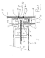
- Figure 1 is shown in cross section one part of a curtain wall system including one frame member 10 of a series of such frame members which are arranged in parallel spaced relationship along an open front face of a building. Attached across the space between each frame member 10 and the next adjacent frame member is a plurality of panels 11. The panels 11 meet at the frame member 10 so that two such panels 11 and 11 A have edges which are closely adjacent and overlie the frame member 10. The panels are arranged perpendicular to the frame members so as to span the frame members and form a front surface for the building.
- the panels are typically a UV reflecting or absorbing glass with panels of aluminum or other non-transparent material used to cover part of the face particularly at the space between the ceiling and floor.
- the present invention is primarily concerned with the construction of the frame member 10 as described in more detail hereinafter.
- the panel 11A includes an outer sheet 12 of glass and an inner sheet 13 of glass which are held in spaced position by a central spacer 14 to form a sealed window unit.
- the glass sheets are held against the spacer 14 by a suitable adhesive materials so that the glass sheets are held at the required spacing and are held together as a structural member by the spacer 14.
- a rubber spacer 15 is positioned between the inner sheet 13 of glass and an outside surface of the frame member 10.
- the rubber spacer includes keying elements 16 which hold the spacer in engagement with the outer face of the frame member.
- a setting block 17 is located on a cylindrical protuberance 18 of the outer face of the frame member and defines a sleeve for receiving a fastener 19 including a screw thread section 20.
- a mounting flange 21 engages against a portion of the panel 12 and holds that portion pressed against the setting block 17. The mounting flange 21 is clamped in place by the threaded fastener 19 which extends through the protuberance 18 and into the structure of the frame member 10 as described in more detail hereinafter.
- edges of the panels are clamped against the outer face of the frame member so that these edges are held in fixed position against the frame member against movement inwardly and outwardly of the building and against movement away from the frame members.
- the exterior of the building is beyond the outer glass sheet 11A as indicated at E and the interior of the building is inwardly of the exterior panels as indicated at I.
- the panels form the exterior sheet and the frame members 10 are located inwardly of that exterior sheet within the building structure at the opening within the building.
- the mounting flange 21 applies pressure against only the inside sheet 13 of the glass and the outside sheet 12 is held in position by its attachment to the inside sheet.
- similar arrangements can be provided which include a tape on the outside so that the pressure is applied against the outer sheet 12.
- a bead 22 of a filler material is located in the space between the edges 23 and 24 of the outer sheets 12.
- the frame member 10 is generally rectangular so as to provide an inner wall 30 and two side walls 31 and 32.
- the frame member further includes the outwardly facing mounting structure 33 which carries the external sheathing panels. As previously described, this includes keying elements 16 which cooperate with the spacer 15 together with the protuberance 18 along the center of the mounting portion 13.
- the mounting portion 13 includes a wall 34 parallel to the wall 30 and at right angles to the side walls 31 and 32.
- the shape of the frame members is not necessarily rectangular so that the side walls 31 and 32 may converge or diverge so that the width of the inner wall 30 may be different from the width of the outer wall 33.
- An additional cross wall 34 parallel to the walls 30 and 33 is provided at a position therebetween so as to define two hollow chambers 35 and 36 within the frame member.
- the frame member 10 is formed by cutting a required length from a pultruded lineal.
- pultrusion is a known technique for manufacturing in effect continuously extending parts which are parts of a constant cross section which are then cut to length after the part is set.
- the frame members When the system is used in a curtain wall construction, typically the frame members are cut to a length so that they span a distance greater than one story of the building on which the curtain wall is applied. Typically the frame members span two such stories and are connected end to end so that the frame member as connected extends from the bottom of the building through to the top of the building or at least through a height of the building on which the curtain wall is intended to be applied. Suitable fastening arrangements for connecting the end of one lineal piece to the next are well known and available to persons skilled in the art.
- the frame members are fastened to the floor of each story again using bracket arrangements well known to a person skilled in the art
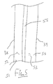
- FIG. 3 a portion of one wall of the frame member 10 is shown as indicated at 31.
- This wall is formed from a resin material 37 which extends through the whole body of the frame member and thus extends from an exterior surface 38 through the interior of each wall through an interior surface 39 of the frame member.
- the outside surfaces 38 and 39 are formed from resin material.
- the layers 42 and 43 are formed from a pre-formed mat of fibers which include fibers which deviate from the longitudinal direction. Mats of various types can be used including non-woven and woven mats but in most cases non woven mats are used where the fibers are in effect randomly oriented through the structure. This provides strength in two directions as is well known in the pultrusion technique.
- the mat 42 which is located on the inside surface of the hollow wraps around the whole inside surface with an overlap at the point 42A to form a continuous inner mat.
- the mat 43 on the outer surface of the part is formed in separate pieces 43A, 43B and 43C. This allows the corner 60 where the mat portions 43A and 43B meet and the corner 61 where the mat portions 43B and 43C meet to be sharper than is typical in pultrusion without forming folds of bends in the mat portions as they enter the pultrusion die.
- Sharp corners that are corners of very small radius are preferred in this construction to reduce the gap where the edge of the horizontal frame members meets the corner of the vertical frame members.
- This radius and the gap formed thereby can also be accommodated by moving the horizontal frame members slightly outwardly by a distance approximately equal to the radius of curvature and taking up the extra distance caused by this movement at the outside edge in the compression of the rubber spacer 15.
- FIG 1 a metal tube 70 which is inserted into the hollow 36 to act as a screw retention member for holding the screws 20 against pulling out of the pultruded frame member.
- the tube is inserted in the hollow 36 only at the screws. However it is still an additional component which must be inserted as an extra step and includes additional cost.
- the tube is replaced by an extra layer of mat 81 in the cross member 34 and an extra layer 81 in the outer cross member 33ln both cases the extra layer is inserted approximately mid way between the outer an inner surfaces and thus is spaced from the outer and inner mats.
- the shape of the frame member with the inner wall 30 and the side walls 31 and 32 may be rectangular as shown or may be curved so that the side walls smoothly converge into the inner wall and form a part cylindrical shape in the inside facing the interior of the building.
- the horizontal frame members may be manufactured of a different pultruded profile having depth from the outer cross-wall to the inner wall which is only sufficient to reach the area where the side walls of the vertical frame members are parallel and before the curvature commences.
- the horizontal frame members may be of reduced dimension in the direction at right angles to the exterior cladding panels since the strength requirement for the horizontal members is significantly less.
- the formation of the part by pultrusion causes the fibers to be contained within the resin body so that the fibers are slightly spaced from the surfaces 38 and 39 thus presenting at the exterior surfaces a structure formed by the resin.
- Figure 4 is shown an arrangement in which the reinforcing fibers include a mat 45, 46 and an exterior veil layer 47, 48.
- the positioning of a veil outside the mat at the respective surface 38,39 tends to increase the amount of resin at the surface and to space the coarse fibers of the mat layer from the surface.
- the frame member is formed so that the walls 30, 31 and 32 are of substantially the same thickness.
- these walls have identical thickness.
- the mandrel which forms the hollow can move during the pultrusion process thus changing the thicknesses of the walls.
- the walls may vary in thickness so that one of the walls is thicker than the other by up to 20%. It is preferred that the process is sufficiently controlled so that the variations and thickness are less than 15% and preferably less than 10%.
- the thickness of the walls is at least 0.090 inch and more preferably in the range of 0.090 inch to 0.5 inch.
- This thickness of the pultruded wall is relatively thick. It has been found by the present inventors that the selection of the relatively thick wall together with the constant thickness through the walls 30, 31 and 32 provides a situation where the external surface defined by the resin is of a constant appearance. Thus all of the exposed outer surfaces of the walls of the frame member from the edges 50 and 51 at the outer mounting portion through the whole of the side wall 31, the inner wall 30 and the side wall 32 have a constant processing characteristic leading to a constant appearance of the outside surface of the resin.
- the resin itself thus provides a hard resistant coating without the possibility of the coating being scratched away.
- the resin itself is resistant to chipping, scratching and abrasion so that it retains the attractive outside appearance.
- Suitable mats which can be used in the present invention are available as follows:
- the difference between the mat and the veil is that the veil is formed of finer fibers so as to reduce the amount of the appearance of the fiber at the surface and the location of the veil outside the mat means that it provides less strength reinforcement and more resin retention.
- the thickness of the mounting portion wall 33 and the cross wall 34 can vary relative to the walls 30, 31 and 32 since these have no outward visibility and thus the surface characteristics can change.
- the pultruded member described above provides better scratch resistance and also better chemical resistance than conventional coatings or anodized aluminium.
- the frame members are located inwardly of the exterior sheeting.
- the exterior sheeting may be transparent, typically such transparent sheeting includes UV resistant layers or reflective layers so that the frame member is protected against UV degradation caused by the penetration of UV light.
- typical UV stabilizers and pigments available for pultrusion and compatible with the resin being used can also be used.
- FIG. 5 is shown alternative arrangement in which the wall is formed again from resin between the surfaces 38 and 39.
- the wall is reinforced by fiber layers but in this case the fiber layers include a layer 51 which is formed from longitudinally extending fibers 52.
- a second layer of longitudinally extending fibers 53 is provided at layer 54.
- An additional reinforcing mat layer 55 is provided to provide structural strength.
- the roving layers 51 and 54 are located at the surfaces 38 and 39 thus providing a different appearance effect at the surfaces 38 and 39.
- Such rovings can be provide a wood grain effect in appearance due to the longitudinal nature of the fibers at the surface where they can be seen just below the surface within the resin.
- the thickness of the part is such that the fibers beneath the surface of the resin do not provide significant three dimensional pultrusion through the resin or vary the smoothness of the resin surface and the appearance of the fibers is primarily visual rather than having any relief effect.
Landscapes
- Engineering & Computer Science (AREA)
- Architecture (AREA)
- Physics & Mathematics (AREA)
- Electromagnetism (AREA)
- Civil Engineering (AREA)
- Structural Engineering (AREA)
- Load-Bearing And Curtain Walls (AREA)
- Moulding By Coating Moulds (AREA)
Applications Claiming Priority (1)
| Application Number | Priority Date | Filing Date | Title |
|---|---|---|---|
| CA 2644212 CA2644212A1 (en) | 2008-11-14 | 2008-11-14 | A pultruded part for use as a frame member for an exterior wall construction for a building |
Publications (1)
| Publication Number | Publication Date |
|---|---|
| EP2186960A2 true EP2186960A2 (de) | 2010-05-19 |
Family
ID=41338671
Family Applications (1)
| Application Number | Title | Priority Date | Filing Date |
|---|---|---|---|
| EP20090175293 Withdrawn EP2186960A2 (de) | 2008-11-14 | 2009-11-06 | Fachwerkstäbe für eine vorgehängte Fassade |
Country Status (2)
| Country | Link |
|---|---|
| EP (1) | EP2186960A2 (de) |
| CA (1) | CA2644212A1 (de) |
Cited By (4)
| Publication number | Priority date | Publication date | Assignee | Title |
|---|---|---|---|---|
| ITUB20159339A1 (it) * | 2015-12-23 | 2017-06-23 | Univ Politecnica Delle Marche | Sistema per la realizzazione di facciate di edifici. |
| CN111749379A (zh) * | 2020-07-29 | 2020-10-09 | 中亿丰(苏州)绿色建筑发展有限公司 | 一种竖挂式陶板幕墙横向胶条防水系统及其安装工艺 |
| CN117266425A (zh) * | 2023-09-11 | 2023-12-22 | 中国建筑第六工程局有限公司 | 一种玻璃幕墙后置埋件 |
| CN117489011A (zh) * | 2023-11-24 | 2024-02-02 | 成都江河幕墙系统工程有限公司 | 一种单元式玻璃幕墙 |
Citations (4)
| Publication number | Priority date | Publication date | Assignee | Title |
|---|---|---|---|---|
| US5129184A (en) | 1991-03-29 | 1992-07-14 | Polygon Company | Magnetic sealing gasket |
| US5324377A (en) | 1990-08-16 | 1994-06-28 | Omniglass Ltd. | Pultrusion method including transverse fibers |
| WO2000078529A1 (en) | 1999-06-21 | 2000-12-28 | Pella Corporation | Pultruded part and method of preparing a reinforcement mat for the part |
| US6746747B2 (en) | 2001-06-14 | 2004-06-08 | Omniglass Ltd. | Pultruded part reinforced by longitudinal and transverse fibers |
-
2008
- 2008-11-14 CA CA 2644212 patent/CA2644212A1/en not_active Abandoned
-
2009
- 2009-11-06 EP EP20090175293 patent/EP2186960A2/de not_active Withdrawn
Patent Citations (4)
| Publication number | Priority date | Publication date | Assignee | Title |
|---|---|---|---|---|
| US5324377A (en) | 1990-08-16 | 1994-06-28 | Omniglass Ltd. | Pultrusion method including transverse fibers |
| US5129184A (en) | 1991-03-29 | 1992-07-14 | Polygon Company | Magnetic sealing gasket |
| WO2000078529A1 (en) | 1999-06-21 | 2000-12-28 | Pella Corporation | Pultruded part and method of preparing a reinforcement mat for the part |
| US6746747B2 (en) | 2001-06-14 | 2004-06-08 | Omniglass Ltd. | Pultruded part reinforced by longitudinal and transverse fibers |
Cited By (5)
| Publication number | Priority date | Publication date | Assignee | Title |
|---|---|---|---|---|
| ITUB20159339A1 (it) * | 2015-12-23 | 2017-06-23 | Univ Politecnica Delle Marche | Sistema per la realizzazione di facciate di edifici. |
| WO2017108402A1 (en) * | 2015-12-23 | 2017-06-29 | Universita' Politecnica Delle Marche | System for making building façades. |
| CN111749379A (zh) * | 2020-07-29 | 2020-10-09 | 中亿丰(苏州)绿色建筑发展有限公司 | 一种竖挂式陶板幕墙横向胶条防水系统及其安装工艺 |
| CN117266425A (zh) * | 2023-09-11 | 2023-12-22 | 中国建筑第六工程局有限公司 | 一种玻璃幕墙后置埋件 |
| CN117489011A (zh) * | 2023-11-24 | 2024-02-02 | 成都江河幕墙系统工程有限公司 | 一种单元式玻璃幕墙 |
Also Published As
| Publication number | Publication date |
|---|---|
| CA2644212A1 (en) | 2010-05-14 |
Similar Documents
| Publication | Publication Date | Title |
|---|---|---|
| US8863454B2 (en) | Pultruded part for use as a frame member for an exterior wall construction for a building | |
| US3332192A (en) | Interlocking panel assembly | |
| CZ219894A3 (en) | Safety glass element with heat-insulating properties and process for producing thereof | |
| GB2465430A (en) | Fireproof door structure | |
| CZ292894A3 (en) | Hollow linear structural element made of thermoplastic material | |
| US20200378134A1 (en) | Metal or alloy framed insulated building cladding system | |
| EP2186960A2 (de) | Fachwerkstäbe für eine vorgehängte Fassade | |
| EP1600596B1 (de) | An einzelnen Punkten abgestützten Vorhangglasfassaden | |
| US8146312B2 (en) | Garage door and a method of making a garage door | |
| CN2806605Y (zh) | 装配式隔墙吊顶板及其安装结构 | |
| RU98024U1 (ru) | Облицовочная панель | |
| RU2361984C1 (ru) | Стеклопанель для заполнения проемов фасадных систем | |
| CN205476104U (zh) | 一种高耐久性复合彩钢瓦 | |
| JP2761410B2 (ja) | 壁耐火目地構造 | |
| EP1477632B1 (de) | Kunststoffstockrahmen | |
| KR200336335Y1 (ko) | 마감재가 부착된 외피판 받침지지대와 공기층이 형성된이중 복합패널 | |
| KR102812323B1 (ko) | 모듈러 건축을 위한 외벽패널 설치구조 | |
| CN212453424U (zh) | 一种增强型保温一体板 | |
| CN220247319U (zh) | 一种聚氨酯玻璃幕墙 | |
| CN221609269U (zh) | 一种珐琅钢板屋顶安装结构 | |
| CN215858730U (zh) | 一种防火隔热型铝单板 | |
| EP4379161A1 (de) | Dachfenster mit polymerprofil mit einer hautschicht | |
| CN214574924U (zh) | 一种防水保温石材复合隔墙 | |
| KR200197024Y1 (ko) | 열반사 방지 차광코팅에 의한 팽창방지 단열동판넬 | |
| KR20060000733A (ko) | 건축용 외장재 |
Legal Events
| Date | Code | Title | Description |
|---|---|---|---|
| PUAI | Public reference made under article 153(3) epc to a published international application that has entered the european phase |
Free format text: ORIGINAL CODE: 0009012 |
|
| AK | Designated contracting states |
Kind code of ref document: A2 Designated state(s): AT BE BG CH CY CZ DE DK EE ES FI FR GB GR HR HU IE IS IT LI LT LU LV MC MK MT NL NO PL PT RO SE SI SK SM TR |
|
| AX | Request for extension of the european patent |
Extension state: AL BA RS |
|
| STAA | Information on the status of an ep patent application or granted ep patent |
Free format text: STATUS: THE APPLICATION IS DEEMED TO BE WITHDRAWN |
|
| 18D | Application deemed to be withdrawn |
Effective date: 20130601 |