EP2186590A1 - Vibration-suppressing mechanism for gear-shaping machine - Google Patents
Vibration-suppressing mechanism for gear-shaping machine Download PDFInfo
- Publication number
- EP2186590A1 EP2186590A1 EP08853372A EP08853372A EP2186590A1 EP 2186590 A1 EP2186590 A1 EP 2186590A1 EP 08853372 A EP08853372 A EP 08853372A EP 08853372 A EP08853372 A EP 08853372A EP 2186590 A1 EP2186590 A1 EP 2186590A1
- Authority
- EP
- European Patent Office
- Prior art keywords
- balancer
- shaft
- main
- crank
- vibration
- Prior art date
- Legal status (The legal status is an assumption and is not a legal conclusion. Google has not performed a legal analysis and makes no representation as to the accuracy of the status listed.)
- Granted
Links
- 230000007246 mechanism Effects 0.000 title claims abstract description 41
- 238000010862 gear shaping Methods 0.000 title 1
- 230000014509 gene expression Effects 0.000 description 5
- 238000010586 diagram Methods 0.000 description 2
- 230000000694 effects Effects 0.000 description 1
- 238000003754 machining Methods 0.000 description 1
- 238000007493 shaping process Methods 0.000 description 1
Images


Classifications
-
- B—PERFORMING OPERATIONS; TRANSPORTING
- B23—MACHINE TOOLS; METAL-WORKING NOT OTHERWISE PROVIDED FOR
- B23F—MAKING GEARS OR TOOTHED RACKS
- B23F23/00—Accessories or equipment combined with or arranged in, or specially designed to form part of, gear-cutting machines
- B23F23/10—Arrangements for compensating irregularities in drives or indexing mechanisms
-
- B—PERFORMING OPERATIONS; TRANSPORTING
- B23—MACHINE TOOLS; METAL-WORKING NOT OTHERWISE PROVIDED FOR
- B23F—MAKING GEARS OR TOOTHED RACKS
- B23F5/00—Making straight gear teeth involving moving a tool relatively to a workpiece with a rolling-off or an enveloping motion with respect to the gear teeth to be made
- B23F5/12—Making straight gear teeth involving moving a tool relatively to a workpiece with a rolling-off or an enveloping motion with respect to the gear teeth to be made by planing or slotting
- B23F5/16—Making straight gear teeth involving moving a tool relatively to a workpiece with a rolling-off or an enveloping motion with respect to the gear teeth to be made by planing or slotting the tool having a shape similar to that of a spur wheel or part thereof
-
- B—PERFORMING OPERATIONS; TRANSPORTING
- B23—MACHINE TOOLS; METAL-WORKING NOT OTHERWISE PROVIDED FOR
- B23Q—DETAILS, COMPONENTS, OR ACCESSORIES FOR MACHINE TOOLS, e.g. ARRANGEMENTS FOR COPYING OR CONTROLLING; MACHINE TOOLS IN GENERAL CHARACTERISED BY THE CONSTRUCTION OF PARTICULAR DETAILS OR COMPONENTS; COMBINATIONS OR ASSOCIATIONS OF METAL-WORKING MACHINES, NOT DIRECTED TO A PARTICULAR RESULT
- B23Q11/00—Accessories fitted to machine tools for keeping tools or parts of the machine in good working condition or for cooling work; Safety devices specially combined with or arranged in, or specially adapted for use in connection with, machine tools
- B23Q11/0032—Arrangements for preventing or isolating vibrations in parts of the machine
- B23Q11/0035—Arrangements for preventing or isolating vibrations in parts of the machine by adding or adjusting a mass, e.g. counterweights
-
- Y—GENERAL TAGGING OF NEW TECHNOLOGICAL DEVELOPMENTS; GENERAL TAGGING OF CROSS-SECTIONAL TECHNOLOGIES SPANNING OVER SEVERAL SECTIONS OF THE IPC; TECHNICAL SUBJECTS COVERED BY FORMER USPC CROSS-REFERENCE ART COLLECTIONS [XRACs] AND DIGESTS
- Y10—TECHNICAL SUBJECTS COVERED BY FORMER USPC
- Y10T—TECHNICAL SUBJECTS COVERED BY FORMER US CLASSIFICATION
- Y10T408/00—Cutting by use of rotating axially moving tool
- Y10T408/36—Machine including plural tools
- Y10T408/375—Coaxial tools
- Y10T408/378—Coaxial, opposed tools
- Y10T408/3796—Coaxial, opposed tools with interconnected means to simultaneously feed tools
-
- Y—GENERAL TAGGING OF NEW TECHNOLOGICAL DEVELOPMENTS; GENERAL TAGGING OF CROSS-SECTIONAL TECHNOLOGIES SPANNING OVER SEVERAL SECTIONS OF THE IPC; TECHNICAL SUBJECTS COVERED BY FORMER USPC CROSS-REFERENCE ART COLLECTIONS [XRACs] AND DIGESTS
- Y10—TECHNICAL SUBJECTS COVERED BY FORMER USPC
- Y10T—TECHNICAL SUBJECTS COVERED BY FORMER US CLASSIFICATION
- Y10T409/00—Gear cutting, milling, or planing
- Y10T409/10—Gear cutting
- Y10T409/100636—Gear cutting with compensation for backlash in drive means
-
- Y—GENERAL TAGGING OF NEW TECHNOLOGICAL DEVELOPMENTS; GENERAL TAGGING OF CROSS-SECTIONAL TECHNOLOGIES SPANNING OVER SEVERAL SECTIONS OF THE IPC; TECHNICAL SUBJECTS COVERED BY FORMER USPC CROSS-REFERENCE ART COLLECTIONS [XRACs] AND DIGESTS
- Y10—TECHNICAL SUBJECTS COVERED BY FORMER USPC
- Y10T—TECHNICAL SUBJECTS COVERED BY FORMER US CLASSIFICATION
- Y10T74/00—Machine element or mechanism
- Y10T74/21—Elements
- Y10T74/2173—Cranks and wrist pins
- Y10T74/2183—Counterbalanced
- Y10T74/2184—Vibration dampers
Definitions
- the present invention relates to a vibration-reduction mechanism for a gear cutting machine that performs gear cutting on a gear blank with a rotary tool attached to a main shaft made to move reciprocally by a crank mechanism.
- Gear cutting machines such as gear shapers, are provided as conventional machines to perform gear cutting on a gear blank with a rotary tool.
- a gear cutting machine of this type When a gear cutting machine of this type is used, a workpiece (gear blank) is formed into a desired gear shape by making a rotary cutter (rotary tool) and the rotating workpiece mesh with each other and then making the cutter move reciprocally in the axial direction of the workpiece.
- the reciprocating motion of the cutter is achieved by making a main shaft to which the cutter is attached move in its axial direction by moving a crank of a crank mechanism.
- Such reciprocating motion of the main shaft produces vibrations in the machine due to the inertial force of the main shaft and the like. The vibrations may possibly affect negatively the machining accuracy. Accordingly, as a countermeasure for such vibrations in conventional gear cutting machines, a balancer weight is provided on the outer perimeter of a crank shaft of the crank mechanism (see, Patent Document 1).
- the conventional gear cutting machines are capable of changing the stroke width of the reciprocating motion of the cutter so as to deal with workpieces of various face widths.
- the changing of the stroke width is naturally accompanied by the changing of the magnitude of the vibrations caused by the reciprocating motion of the main shaft.
- various gear cutting machines are provided with vibration-reduction mechanisms to adjust easily the weight of the balancer weight in accordance with the stroke width (see Patent Documents 2 to 4).
- the main shaft When a workpiece is to be formed into a helical gear, the main shaft has to be twisted so that the lead can correspond to the helical angle. Accordingly, the main shaft performs a twisting (spiral) motion with a predetermined lead angle corresponding to the specifications of the helical gear into which the workpiece is to be formed.
- the twisting motion that the main shaft always performs during its reciprocating motion produces an inertial force attributable to the twisting motion of the main shaft.
- the twisting motion of the main shaft in the balance of forces achieved by the balancer weight is not taken into account in the design of conventional vibration-reduction mechanisms. Accordingly, when the workpiece is formed into a helical gear, the vibration reduction may not be achieved with certainty.
- An object of the present invention is, therefore, to provide a vibration-reduction mechanism for a gear cutting machine capable of reducing mechanical vibrations in the gear cutting of a helical gear by selecting an optimal balancer weight.
- a vibration-reduction mechanism for a gear cutting machine to solve the above-described problem is a vibration-reduction mechanism for a gear cutting machine that performs gear cutting on a gear blank with a rotary tool attached to a main shaft made to move reciprocally by a crank mechanism, the vibration-reduction mechanism characterized by comprising:
- a vibration-reduction mechanism for a gear cutting machine according to a second invention to solve the above-described problem is the vibration-reduction mechanism for a gear cutting machine according to the first invention characterized in that the main balancer weights include:
- a vibration-reduction mechanism for a gear cutting machine according to a third invention to solve the above-described problem is the vibration-reduction mechanism for a gear cutting machine according to any one of the first and the second inventions characterized in that the sub balancer weights are disposed, in the axial direction of the crank shaft, at same positions as the position of the mass center of the main shaft in the axial direction of the crank shaft.
- the mechanical vibrations can be reduced with certainty by taking the twisting motion of the main shaft in accordance with the helical angle to be formed in the gear blank into consideration when each balancer weight is selected.
- Fig. 1 is a front elevation illustrating a vibration-reduction mechanism for a gear cutting machine according to an embodiment of the present invention.
- Fig. 2 is a sectional view taken along and seen as indicated by the arrow line A-A of Fig. 1 .
- Fig. 3 is a general configuration diagram of the vibration-reduction mechanism.
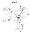
- Fig. 4 is a front elevation illustrating the basic principle of the vibration-reduction mechanism.
- Fig. 5 is a top plan view illustrating the basic principle of the vibration-reduction mechanism.
- the gear cutting machine equipped with a vibration-reduction mechanism that Figs. 1 to 3 show is a gear shaper to perform the shaping of a workpiece W into, for example, a helical gear.
- the X-axis, Y-axis, and Z-axis in the drawings are three axes that orthogonally intersect one another.
- the X-axis direction is the direction along the horizontal width of the machine
- the Y-axis direction is the direction along the horizontal length of the machine
- the Z-axis direction is the vertical direction.
- the gear cutting machine includes a column 11.
- a main-shaft motor 12 is attached to the top surface of the column 11 with a bracket 13.
- a gear box 14 is provided so as to be opposed to the main-shaft motor 12.
- crank shaft 15, and balancer shafts 16 and 17 are rotatably supported so as to be in parallel to one another.
- Gears 18, 19, and 20 are provided respectively on the crank shaft 15 and the balancer shafts 16 and 17.
- the gear 18 on the crank shaft 15 meshes with the gear 19 on the balancer shaft 16 while the gear 19 on the balancer shaft 16 meshes with the gear 20 on the balancer shaft 17.
- the gear 18 and the gear 20 are offset from each other in the Y-axis direction. Accordingly, the gear 18 and the gear 20 do not interfere with each other even while these gears 18 and 20 are rotating.
- the rear ratio between every two of the gears 18, 19, and 20 is set at 1 to 1, so that all the crank shaft 15 and the balancer shafts 16 and 17 rotate at the same speed. Specifically, when the crank shaft 15 rotates, the rotation is transmitted to the balancer shaft 16, the rotation of which is then transmitted to the balancer shaft 17. In this event, the crank shaft 15 and the balancer shaft 16 rotate in the opposite directions to each other while the crank shaft 15 and the balancer shaft 17 rotate in the same direction. In addition, when the crank shaft 15 rotates by an angle ⁇ , each of the balancer shafts 16 and 17 rotates by the angle ⁇ , as well.
- a motorized pulley 21 is provided on the output shaft of the main-shaft motor 12.
- a pulley 22 is provided on the rear end of the crank shaft 15.
- a timing belt 23 is looped around the motorized pulley 21 and the pulley 22.
- a connecting rod 25 is supported on the front end of the crank shaft 15 with a crank pin 24.
- the position of the crank pin 24 is offset from the center of the crank shaft 15 by a distance S, that is, the connecting rod 25 is eccentrically supported with respect to the crank shaft 15.
- the bottom end of the connecting rod 25 is supported on an unillustrated spherical bearing disposed at the base end of a main shaft 26. To the leading end of the main shaft 26, a cutter T is detachably attached.
- the main shaft 26 penetrates a cylindrical guide member 27, and is supported by the inner circumferential surface of the guide member 27.
- the main shaft 26 thus supported is capable of sliding.
- a groove (not illustrated) is formed in the inner circumferential surface of the guide member 27 so as to correspond to the helical angle of the helical gear into which the workpiece W is to be formed.
- An engagement portion (not illustrated) formed in the outer circumferential surface of the main shaft 26 engages with the groove. Accordingly, as the main shaft 26 slides inside the guide member 27, the main shaft 26 performs twisting (spiral) motion corresponding to the helical angle of the helical gear into which the workpiece W is to be formed.
- a rotary table 28 is rotatably supported at a position opposed to the column 11. Onto the top surface of the rotary table 28, the workpiece W is detachably attached with an unillustrated attachment jig.
- a main balancer weight 41 of a mass of m B2 is detachably attached to the front-end side of the crank shaft 15 while a main balancer weight 41 of a mass of m B1 is detachably attached to the rear-end side of the crank shaft 15.
- the main balancer weight 41 is formed into a substantially semicircular shape.
- the main balancer weight 41 is disposed at the inner side of the connecting rod 25 in the Y-axis direction, and the phase of the main balancer weight 41 is offset from the phase of the crank pin 24 by 180°.
- the main balancer weight 42 is formed also into a substantially semicircular shape.
- the main balancer weight 42 is disposed at the outer side of the pulley 22 in the Y-axis direction, and the phase of the main balancer weight 42 is the same as the phase of the crank pin 24, that is, the phase of the main balancer weight 42 is offset from the phase of the main balancer weight 41 by 180°.
- a sub balancer weight 43 of a mass of m s2 is detachably attached to the front end of the balancer shaft 16 while a sub balancer weight 44 of a mass of m S1 is detachably attached to the rear end of the balancer shaft 16.
- a sub balancer weight 45 of a mass of m S2 is detachably attached to the front end of the balancer shaft 17 while a sub balancer weight 46 of a mass of m S1 is detachably attached to the rear end of the balancer shaft 17.
- These sub balancer weights 43 to 46 are formed into substantially semicircular shapes.
- the phases of the sub balancer weights 43 and 45 are offset from the phases of the sub balancer weights 44 and 46 by 180°, respectively.
- the main-shaft motor 12 is rotated, and the rotation of the main-shaft motor 12 is transmitted via the timing belt 23 so as to rotate the crank shaft 15.
- the rotation of the crank shaft 15 makes the connecting rod 25 rotate.
- the rotation of the connecting rod 25 makes the main shaft 26 move reciprocally in the Z-axis directions by a stroke width of 2S.
- the main shaft 26 slides inside the guide member 27.
- the rotating cutter T that meshes with the rotating workpiece W moves reciprocally by a stroke width that is longer than the face width of the workpiece W, and the cutter T performs twisting motion corresponding to the helical angle that the workpiece W is to have. In this way, the workpiece W is cut with the cutter T.
- the balancer shafts 16 and 17 also rotate.
- m rev denotes a movable mass for the stroke adjustment of the main shaft 26
- M denotes a mass equivalent to a reciprocating portion
- the translational unbalance between the movable mass for the stroke adjustment m rev and the mass equivalent to the reciprocating portion M in the Z-axis direction is designed to be resolved by attaching the main balancer weight 41 of a mass of m B2 and the main balancer weight 42 of a mass of m B1 .
- the translational unbalance between the main balancer weight 41 of a mass of m B2 and the main balancer weight 42 of a mass of m B1 in the X-axis direction is greater than the movable mass for the stroke adjustment m rev
- the translational unbalance is designed to be resolved by attaching the sub balancer weights 43 and 45 each of which has a mass of m S2 and the sub balancer weights 44 and 46 each of which has a mass of m S1 .
- the position of the mass center of the main shaft 26 and the position of the mass center of the main balancer weight 41 are offset from each other in the axis direction of the crank shaft 15 (Y-axis direction) by their attachment structure. Nevertheless, the balance in the axial direction of the crank shaft 15 can be achieved by attaching the main balancer weight 42 at the opposite side to the side where the main balancer weight 41 is attached.
- the balance needs to be achieved under the condition that, as the mass equivalent to the reciprocating portion M, not only the simple addition of the mass of the connecting rod 25 and the mass of the main shaft 26 but also an equivalent mass of the twisting motion of the main shaft 26 has to be taken into consideration.
- m B1 , M B2 masses of the main balancer weights
- m S1 , m S2 masses of the sub balancer weights
- M mass equivalent to the reciprocating portion
- m rev movable mass for the stroke adjustment of the main shaft
- ⁇ rotational angle [rad]
- S main-shaft stroke width / 2
- L offset amount of the center of the mass of the main shaft in the Y-axis direction
- h 1 distance in the Y-axis direction from the X-axis to the main balancer weight h s1
- h s2 distances in the Y-axis direction from the X-axis to the sub balancer weights
- R B1 , R B2 radii of rotation of the main balancer weights (distances to the centers of mass)
- R S1 , R S2 radii of rotation of the main balancer weights (distances to the
- the mass equivalent to the reciprocating portion M can be given by the following mathematical expression (1).
- m g mass of the reciprocating portion of the main shaft (including the cutter T and the like)
- m gr mass equivalent to the main-shaft twisting motion at the time of forming a helical gear
- m gc part of the mass of the connecting rod contributing to the translational portion
- I rotational moment of inertia of the main shaft rotating about the Z-axis
- L g lead of the main shaft corresponding to the helical angle of the helical gear
- m c mass of the connecting rod.
- the masses m B1 , m B2 , m S1 , and m S2 can be set so as to satisfy the mathematical expressions (2)' to (5)" given above.
- the positions of the sub balancer weights 43 and 45 in the Y-axis direction may be located at the same position as the position of the mass center of the main shaft 26 in the Y-axis direction.
- h S2 L.
- the mass m S1 of each of the sub balancer weights 44 and 46 can be made to be zero permanently, so that it is no longer necessary to provide the sub balancer weights 44 and 46.
- a simpler configuration of the vibration-reduction mechanism can be achieved, and an easier selection of the balancer weights can be achieved.
- the vibration-reduction mechanism for a gear cutting machine of the present invention when the balancer weights 41 to 46 are selected for the cutting a workpiece W into a helical gear, the forces in the X-axis direction and in the Y-axis direction as well as the rotational moments about the X-axis and about the Z-axis are balanced, with the twisting motion of the main shaft 26 corresponding to the helical angle to be formed in the work W being taken into consideration. Specifically, when the work W is formed into a helical gear, the main shaft 26 moves reciprocally with the lead (angle) L g corresponding to the helical angle to be formed in the work W.
- the masses m B1 , m B2 , m S1 , and m S2 are set (calculated) and thus the balancer weights 41 to 46 are selected. As a consequence, the vibrations generated in the machine can be reduced with certainty.
- the present invention can be applied to a vibration-reduction mechanism for a gear cutting machine capable of finely adjusting the position where a balancer weight is to be attached when the stroke width of the main shaft is changed.
Landscapes
- Engineering & Computer Science (AREA)
- Mechanical Engineering (AREA)
- Gear Processing (AREA)
- Auxiliary Devices For Machine Tools (AREA)
Abstract
Description
- The present invention relates to a vibration-reduction mechanism for a gear cutting machine that performs gear cutting on a gear blank with a rotary tool attached to a main shaft made to move reciprocally by a crank mechanism.
- Gear cutting machines, such as gear shapers, are provided as conventional machines to perform gear cutting on a gear blank with a rotary tool. When a gear cutting machine of this type is used, a workpiece (gear blank) is formed into a desired gear shape by making a rotary cutter (rotary tool) and the rotating workpiece mesh with each other and then making the cutter move reciprocally in the axial direction of the workpiece.
- The reciprocating motion of the cutter is achieved by making a main shaft to which the cutter is attached move in its axial direction by moving a crank of a crank mechanism. Such reciprocating motion of the main shaft, however, produces vibrations in the machine due to the inertial force of the main shaft and the like. The vibrations may possibly affect negatively the machining accuracy. Accordingly, as a countermeasure for such vibrations in conventional gear cutting machines, a balancer weight is provided on the outer perimeter of a crank shaft of the crank mechanism (see, Patent Document 1).
- The conventional gear cutting machines are capable of changing the stroke width of the reciprocating motion of the cutter so as to deal with workpieces of various face widths. The changing of the stroke width is naturally accompanied by the changing of the magnitude of the vibrations caused by the reciprocating motion of the main shaft. Accordingly, various gear cutting machines are provided with vibration-reduction mechanisms to adjust easily the weight of the balancer weight in accordance with the stroke width (see Patent Documents 2 to 4).
-
- [Patent Document 1] Japanese Utility Model Application Laid-open Publication No.
Sho 60-45640 - [Patent Document 2] Japanese Examined Utility ModelPublication No.
Sho 58-35386 - [Patent Document 3] Japanese Utility Model Application Laid-open Publication No.
Sho 61-97643 - [Patent Document 4] Japanese Utility Model Application Laid-open Publication No.
Sho 61-97644 - When a workpiece is to be formed into a helical gear, the main shaft has to be twisted so that the lead can correspond to the helical angle. Accordingly, the main shaft performs a twisting (spiral) motion with a predetermined lead angle corresponding to the specifications of the helical gear into which the workpiece is to be formed. The twisting motion that the main shaft always performs during its reciprocating motion produces an inertial force attributable to the twisting motion of the main shaft.
- However, the twisting motion of the main shaft in the balance of forces achieved by the balancer weight is not taken into account in the design of conventional vibration-reduction mechanisms. Accordingly, when the workpiece is formed into a helical gear, the vibration reduction may not be achieved with certainty.
- The present invention aims to solve the above-mentioned problem. An object of the present invention is, therefore, to provide a vibration-reduction mechanism for a gear cutting machine capable of reducing mechanical vibrations in the gear cutting of a helical gear by selecting an optimal balancer weight.
- A vibration-reduction mechanism for a gear cutting machine according to a first invention to solve the above-described problem is a vibration-reduction mechanism for a gear cutting machine that performs gear cutting on a gear blank with a rotary tool attached to a main shaft made to move reciprocally by a crank mechanism, the vibration-reduction mechanism characterized by comprising:
- a first balancer shaft and a second balancer shaft which are arranged in parallel to a crank shaft of the crank mechanism, and which rotate synchronously with the crank shaft at a same speed as a speed of the crank shaft, the first balancer shaft rotating in an opposite direction to a rotational direction of the crank shaft and the second balancer shaft rotating in a same direction as the rotational direction of the crank shaft;
- main balancer weights detachably attached onto the crank shaft so as to reduce vibrations in an axial direction of the main shaft; and
- sub balancer weights detachably attached onto the first and the second balancer shafts so as to reduce vibrations in directions that are orthogonal to the axial direction of the main shaft, characterized in that
- the main balancer weights and the sub balancer weights are selected on the basis of a stroke width of the main shaft and on the basis of a helical angle to be formed in the gear blank.
- A vibration-reduction mechanism for a gear cutting machine according to a second invention to solve the above-described problem is the vibration-reduction mechanism for a gear cutting machine according to the first invention characterized in that
the main balancer weights include: - a front-side balancer weight having a phase being offset by 180° from a phase of the main shaft eccentrically supported with respect to a center of the crank shaft; and
- a rear-side balancer weight having a phase being offset by 180° from the phase of the front-side balancer weight so as to solve an imbalance caused by the offset, in an axial direction of the crank shaft, between the position of a mass center of the main shaft and the position of a mass center of the front-side balancer weight.
- A vibration-reduction mechanism for a gear cutting machine according to a third invention to solve the above-described problem is the vibration-reduction mechanism for a gear cutting machine according to any one of the first and the second inventions characterized in that
the sub balancer weights are disposed, in the axial direction of the crank shaft, at same positions as the position of the mass center of the main shaft in the axial direction of the crank shaft. - According to the vibration-reduction mechanism for a gear cutting machine of the present invention, the mechanical vibrations can be reduced with certainty by taking the twisting motion of the main shaft in accordance with the helical angle to be formed in the gear blank into consideration when each balancer weight is selected.
-
- [
FIG. 1] Fig. 1 is a front elevation illustrating a vibration-reduction mechanism for a gear cutting machine according to an embodiment of the present invention. - [
FIG. 2] Fig. 2 is a sectional view taken along and seen as indicated by the arrow line A-A ofFig. 1 . - [
FIG. 3] Fig. 3 is a general configuration diagram of the vibration-reduction mechanism. - [
FIG. 4] Fig. 4 is a front elevation illustrating the basic principle of the vibration-reduction mechanism. - [
FIG. 5] Fig. 5 is a top plan view illustrating the basic principle of the vibration-reduction mechanism. - A vibration-reduction mechanism for a gear cutting machine according to the present invention will be described in detail below with reference to the drawings.
Fig. 1 is a front elevation illustrating a vibration-reduction mechanism for a gear cutting machine according to an embodiment of the present invention.Fig. 2 is a sectional view taken along and seen as indicated by the arrow line A-A ofFig. 1 .Fig. 3 is a general configuration diagram of the vibration-reduction mechanism.Fig. 4 is a front elevation illustrating the basic principle of the vibration-reduction mechanism.Fig. 5 is a top plan view illustrating the basic principle of the vibration-reduction mechanism. - The gear cutting machine equipped with a vibration-reduction mechanism that
Figs. 1 to 3 show is a gear shaper to perform the shaping of a workpiece W into, for example, a helical gear. Note that the X-axis, Y-axis, and Z-axis in the drawings are three axes that orthogonally intersect one another. The X-axis direction is the direction along the horizontal width of the machine, the Y-axis direction is the direction along the horizontal length of the machine, and the Z-axis direction is the vertical direction. - As
Figs. 1 to 3 show, the gear cutting machine includes acolumn 11. A main-shaft motor 12 is attached to the top surface of thecolumn 11 with abracket 13. Agear box 14 is provided so as to be opposed to the main-shaft motor 12. - Inside the
gear box 14, acrank shaft 15, andbalancer shafts Gears crank shaft 15 and thebalancer shafts gear 18 on thecrank shaft 15 meshes with thegear 19 on thebalancer shaft 16 while thegear 19 on thebalancer shaft 16 meshes with thegear 20 on thebalancer shaft 17. - The
gear 18 and thegear 20 are offset from each other in the Y-axis direction. Accordingly, thegear 18 and thegear 20 do not interfere with each other even while thesegears gears crank shaft 15 and thebalancer shafts crank shaft 15 rotates, the rotation is transmitted to thebalancer shaft 16, the rotation of which is then transmitted to thebalancer shaft 17. In this event, thecrank shaft 15 and thebalancer shaft 16 rotate in the opposite directions to each other while thecrank shaft 15 and thebalancer shaft 17 rotate in the same direction. In addition, when thecrank shaft 15 rotates by an angle θ, each of thebalancer shafts - A
motorized pulley 21 is provided on the output shaft of the main-shaft motor 12. Apulley 22 is provided on the rear end of thecrank shaft 15. Atiming belt 23 is looped around themotorized pulley 21 and thepulley 22. - A connecting
rod 25 is supported on the front end of thecrank shaft 15 with acrank pin 24. The position of thecrank pin 24 is offset from the center of thecrank shaft 15 by a distance S, that is, the connectingrod 25 is eccentrically supported with respect to thecrank shaft 15. The bottom end of the connectingrod 25 is supported on an unillustrated spherical bearing disposed at the base end of amain shaft 26. To the leading end of themain shaft 26, a cutter T is detachably attached. - The
main shaft 26 penetrates acylindrical guide member 27, and is supported by the inner circumferential surface of theguide member 27. Themain shaft 26 thus supported is capable of sliding. A groove (not illustrated) is formed in the inner circumferential surface of theguide member 27 so as to correspond to the helical angle of the helical gear into which the workpiece W is to be formed. An engagement portion (not illustrated) formed in the outer circumferential surface of themain shaft 26 engages with the groove. Accordingly, as themain shaft 26 slides inside theguide member 27, themain shaft 26 performs twisting (spiral) motion corresponding to the helical angle of the helical gear into which the workpiece W is to be formed. - A rotary table 28 is rotatably supported at a position opposed to the
column 11. Onto the top surface of the rotary table 28, the workpiece W is detachably attached with an unillustrated attachment jig. - A
main balancer weight 41 of a mass of mB2 is detachably attached to the front-end side of thecrank shaft 15 while amain balancer weight 41 of a mass of mB1 is detachably attached to the rear-end side of thecrank shaft 15. Themain balancer weight 41 is formed into a substantially semicircular shape. Themain balancer weight 41 is disposed at the inner side of the connectingrod 25 in the Y-axis direction, and the phase of themain balancer weight 41 is offset from the phase of thecrank pin 24 by 180°. In addition, themain balancer weight 42 is formed also into a substantially semicircular shape. Themain balancer weight 42 is disposed at the outer side of thepulley 22 in the Y-axis direction, and the phase of themain balancer weight 42 is the same as the phase of thecrank pin 24, that is, the phase of themain balancer weight 42 is offset from the phase of themain balancer weight 41 by 180°. - A
sub balancer weight 43 of a mass of ms2 is detachably attached to the front end of thebalancer shaft 16 while asub balancer weight 44 of a mass of mS1 is detachably attached to the rear end of thebalancer shaft 16. In addition, asub balancer weight 45 of a mass of mS2 is detachably attached to the front end of thebalancer shaft 17 while asub balancer weight 46 of a mass of mS1 is detachably attached to the rear end of thebalancer shaft 17. Thesesub balancer weights 43 to 46 are formed into substantially semicircular shapes. The phases of thesub balancer weights sub balancer weights - Accordingly, to cut the workpiece W with the cutter T, the main-
shaft motor 12 is rotated, and the rotation of the main-shaft motor 12 is transmitted via thetiming belt 23 so as to rotate thecrank shaft 15. The rotation of thecrank shaft 15 makes the connectingrod 25 rotate. The rotation of the connectingrod 25 makes themain shaft 26 move reciprocally in the Z-axis directions by a stroke width of 2S. In this event, themain shaft 26 slides inside theguide member 27. Accordingly, the rotating cutter T that meshes with the rotating workpiece W moves reciprocally by a stroke width that is longer than the face width of the workpiece W, and the cutter T performs twisting motion corresponding to the helical angle that the workpiece W is to have. In this way, the workpiece W is cut with the cutter T. - Incidentally, when the
crank shaft 15 rotates, thebalancer shafts main shaft 26, and M denotes a mass equivalent to a reciprocating portion, the translational unbalance between the movable mass for the stroke adjustment mrev and the mass equivalent to the reciprocating portion M in the Z-axis direction is designed to be resolved by attaching themain balancer weight 41 of a mass of mB2 and themain balancer weight 42 of a mass of mB1. In addition, although the translational unbalance between themain balancer weight 41 of a mass of mB2 and themain balancer weight 42 of a mass of mB1 in the X-axis direction is greater than the movable mass for the stroke adjustment mrev, the translational unbalance is designed to be resolved by attaching thesub balancer weights sub balancer weights main shaft 26 and the position of the mass center of themain balancer weight 41 are offset from each other in the axis direction of the crank shaft 15 (Y-axis direction) by their attachment structure. Nevertheless, the balance in the axial direction of thecrank shaft 15 can be achieved by attaching themain balancer weight 42 at the opposite side to the side where themain balancer weight 41 is attached. - Subsequently, when the
balancer weights 41 to 46 are selected, or when the masses mB1, mB2, mS1, and mS2 are set, the forces in the X-axis direction and in the Y-axis direction as well as the rotational moments about the X-axis and the Z-axis need to be balanced, with the twisting motion of themain shaft 26 corresponding to the helical angle to be formed in the workpiece W being taken into consideration. To put it differently, the balance needs to be achieved under the condition that, as the mass equivalent to the reciprocating portion M, not only the simple addition of the mass of the connectingrod 25 and the mass of themain shaft 26 but also an equivalent mass of the twisting motion of themain shaft 26 has to be taken into consideration. - Now, assume as
Figs. 3 to 5 show, that
mB1, MB2: masses of the main balancer weights,
mS1, mS2: masses of the sub balancer weights,
M: mass equivalent to the reciprocating portion,
mrev: movable mass for the stroke adjustment of the main shaft,
θ: rotational angle [rad],
ω: rotational angle speed [rad/s] = (d/dt) θ,
S: main-shaft stroke width / 2,
L: offset amount of the center of the mass of the main shaft in the Y-axis direction,
h1: distance in the Y-axis direction from the X-axis to the main balancer weight
hs1, hs2: distances in the Y-axis direction from the X-axis to the sub balancer weights,
RB1, RB2: radii of rotation of the main balancer weights (distances to the centers of mass),
RS1, RS2: radii of rotation of the sub balancer weights (distances to the centers of mass),
h: length of the connecting rod,
G: mass center of the connecting rod,
a, b: lengths to the mass center from ends of the connecting rods. - In addition, the mass equivalent to the reciprocating portion M can be given by the following mathematical expression (1).

where
mg: mass of the reciprocating portion of the main shaft (including the cutter T and the like),
mgr: mass equivalent to the main-shaft twisting motion at the time of forming a helical gear,
mgc: part of the mass of the connecting rod contributing to the translational portion,
I: rotational moment of inertia of the main shaft rotating about the Z-axis,
Lg: lead of the main shaft corresponding to the helical angle of the helical gear,
mc: mass of the connecting rod. - Then, the balance of forces in the Z-axis direction, the balance of forces in the X-axis direction, the balance of rotational moments about the Z-axis, and the balance of rotational moments about the X-axis can be expressed by the following mathematical expressions (2) to (5).
-

- In addition, the mathematical expressions (2) to (5) given above can be expressed respectively by the following mathematical expressions (2)' to (5)'.
-

- As has been shown above, the masses mB1, mB2, mS1, and mS2 can be set so as to satisfy the mathematical expressions (2)' to (5)" given above.
- Note that the positions of the
sub balancer weights main shaft 26 in the Y-axis direction. To put it differently, it is allowed that hS2 = L. Accordingly, the mass mS1 of each of thesub balancer weights sub balancer weights - As has been described thus far, according to the vibration-reduction mechanism for a gear cutting machine of the present invention, when the
balancer weights 41 to 46 are selected for the cutting a workpiece W into a helical gear, the forces in the X-axis direction and in the Y-axis direction as well as the rotational moments about the X-axis and about the Z-axis are balanced, with the twisting motion of themain shaft 26 corresponding to the helical angle to be formed in the work W being taken into consideration. Specifically, when the work W is formed into a helical gear, themain shaft 26 moves reciprocally with the lead (angle) Lg corresponding to the helical angle to be formed in the work W. With the mass equivalent (mgr) to the twisting motion of themain shaft 26 being taken into consideration, the masses mB1, mB2, mS1, and mS2 are set (calculated) and thus thebalancer weights 41 to 46 are selected. As a consequence, the vibrations generated in the machine can be reduced with certainty. - The present invention can be applied to a vibration-reduction mechanism for a gear cutting machine capable of finely adjusting the position where a balancer weight is to be attached when the stroke width of the main shaft is changed.
Claims (3)
- A vibration-reduction mechanism for a gear cutting machine that performs gear cutting on a gear blank with a rotary tool attached to a main shaft made to move reciprocally by a crank mechanism, the vibration-reduction mechanism characterized by comprising:a first balancer shaft and a second balancer shaft which are arranged in parallel to a crank shaft of the crank mechanism, and which rotate synchronously with the crank shaft at a same speed as a speed of the crank shaft, the first balancer shaft rotating in an opposite direction to a rotational direction of the crank shaft and the second balancer shaft rotating in a same direction as the rotational direction of the crank shaft;main balancer weights detachably attached onto the crank shaft so as to reduce vibrations in an axial direction of the main shaft; andsub balancer weights detachably attached onto the first and the second balancer shafts so as to reduce vibrations in directions that are orthogonal to the axial direction of the main shaft, characterized in thatthe main balancer weights and the sub balancer weights are selected on the basis of a stroke width of the main shaft and on the basis of a helical angle to be formed in the gear blank.
- The vibration-reduction mechanism for a gear cutting machine according to claim 1 characterized in that
the main balancer weights include:a front-side balancer weight having a phase being offset by 180° from a phase of the main shaft eccentrically supported with respect to a center of the crank shaft; anda rear-side balancer weight having a phase being offset by 180° from the phase of the front-side balancer weight so as to solve an imbalance caused by the offset, in an axial direction of the crank shaft, between the position of a mass center of the main shaft and the position of a mass center of the front-side balancer weight. - The vibration-reduction mechanism for a gear cutting machine according to any one of claims 1 and 2 characterized in that
the sub balancer weights are disposed, in the axial direction of the crank shaft, at same positions as the position of the mass center of the main shaft in the axial direction of the crank shaft.
Applications Claiming Priority (2)
| Application Number | Priority Date | Filing Date | Title |
|---|---|---|---|
| JP2007305319A JP4885116B2 (en) | 2007-11-27 | 2007-11-27 | Vibration suppression mechanism of gear processing machine |
| PCT/JP2008/070887 WO2009069497A1 (en) | 2007-11-27 | 2008-11-18 | Vibration-suppressing mechanism for gear-shaping machine |
Publications (3)
| Publication Number | Publication Date |
|---|---|
| EP2186590A1 true EP2186590A1 (en) | 2010-05-19 |
| EP2186590A4 EP2186590A4 (en) | 2014-03-12 |
| EP2186590B1 EP2186590B1 (en) | 2018-08-22 |
Family
ID=40678400
Family Applications (1)
| Application Number | Title | Priority Date | Filing Date |
|---|---|---|---|
| EP08853372.4A Active EP2186590B1 (en) | 2007-11-27 | 2008-11-18 | Vibration-suppressing mechanism for gear-shaping machine |
Country Status (6)
| Country | Link |
|---|---|
| US (1) | US8651775B2 (en) |
| EP (1) | EP2186590B1 (en) |
| JP (1) | JP4885116B2 (en) |
| CN (1) | CN101678487B (en) |
| TW (1) | TW200940226A (en) |
| WO (1) | WO2009069497A1 (en) |
Cited By (2)
| Publication number | Priority date | Publication date | Assignee | Title |
|---|---|---|---|---|
| EP3363573A1 (en) * | 2017-02-21 | 2018-08-22 | Liebherr-Verzahntechnik GmbH | Device and method for the processing of a work piece on a gear cutting machine |
| CN115179100A (en) * | 2022-08-17 | 2022-10-14 | 万青青 | Machine tool machining scrap separation method |
Families Citing this family (4)
| Publication number | Priority date | Publication date | Assignee | Title |
|---|---|---|---|---|
| US9726081B2 (en) | 2013-07-19 | 2017-08-08 | Borgwarner Inc. | Exhaust-gas turbocharger |
| DE102013015252A1 (en) * | 2013-09-13 | 2015-03-19 | Gleason-Pfauter Maschinenfabrik Gmbh | Coolant supply and thus equipped Wälzschälmaschine and thus executed Wälzschälverfahren |
| KR102657712B1 (en) * | 2019-03-27 | 2024-04-16 | 주식회사 디엔솔루션즈 | Apparatus for reducing vibration of a machine tool spindle and a machine tool including the same |
| CN112326123A (en) * | 2020-05-11 | 2021-02-05 | 苏州喜全软件科技有限公司 | Gear shaping machine active motion dynamic balancing device |
Citations (3)
| Publication number | Priority date | Publication date | Assignee | Title |
|---|---|---|---|---|
| US3808912A (en) * | 1972-11-21 | 1974-05-07 | Minster Machine Co | Arrangement for dynamic balancing of a mechanical press, especially a high speed mechanical press |
| JPS6045640U (en) * | 1983-09-08 | 1985-03-30 | 三菱重工業株式会社 | Machine tool vibration prevention mechanism |
| US20010020421A1 (en) * | 2000-02-22 | 2001-09-13 | Shozou Imanishi | Slide driving device for a press machine |
Family Cites Families (9)
| Publication number | Priority date | Publication date | Assignee | Title |
|---|---|---|---|---|
| JPS5835386Y2 (en) | 1977-09-14 | 1983-08-09 | 本田技研工業株式会社 | gear shaping machine |
| JPS5835386A (en) | 1981-08-25 | 1983-03-02 | Miura Co Ltd | Heat exchanger for recovering heat of blow water |
| JPS6197643U (en) | 1984-12-04 | 1986-06-23 | ||
| JPS6197644U (en) | 1984-12-04 | 1986-06-23 | ||
| JPS61117938U (en) | 1985-01-10 | 1986-07-25 | ||
| JPS61154348U (en) | 1985-03-18 | 1986-09-25 | ||
| JPH069760B2 (en) * | 1986-02-17 | 1994-02-09 | 三菱重工業株式会社 | Reciprocating machine balancer |
| US4966042A (en) * | 1989-02-06 | 1990-10-30 | Brown Arthur E | Balanced reciprocating machines |
| CN2059697U (en) * | 1989-11-08 | 1990-07-25 | 江西工业大学 | Damping device of compressor |
-
2007
- 2007-11-27 JP JP2007305319A patent/JP4885116B2/en active Active
-
2008
- 2008-11-18 WO PCT/JP2008/070887 patent/WO2009069497A1/en active Application Filing
- 2008-11-18 CN CN2008800180933A patent/CN101678487B/en active Active
- 2008-11-18 US US12/602,029 patent/US8651775B2/en active Active
- 2008-11-18 EP EP08853372.4A patent/EP2186590B1/en active Active
- 2008-11-19 TW TW097144739A patent/TW200940226A/en unknown
Patent Citations (3)
| Publication number | Priority date | Publication date | Assignee | Title |
|---|---|---|---|---|
| US3808912A (en) * | 1972-11-21 | 1974-05-07 | Minster Machine Co | Arrangement for dynamic balancing of a mechanical press, especially a high speed mechanical press |
| JPS6045640U (en) * | 1983-09-08 | 1985-03-30 | 三菱重工業株式会社 | Machine tool vibration prevention mechanism |
| US20010020421A1 (en) * | 2000-02-22 | 2001-09-13 | Shozou Imanishi | Slide driving device for a press machine |
Non-Patent Citations (1)
| Title |
|---|
| See also references of WO2009069497A1 * |
Cited By (3)
| Publication number | Priority date | Publication date | Assignee | Title |
|---|---|---|---|---|
| EP3363573A1 (en) * | 2017-02-21 | 2018-08-22 | Liebherr-Verzahntechnik GmbH | Device and method for the processing of a work piece on a gear cutting machine |
| CN115179100A (en) * | 2022-08-17 | 2022-10-14 | 万青青 | Machine tool machining scrap separation method |
| CN115179100B (en) * | 2022-08-17 | 2024-02-09 | 遵义绿环废弃电器电子产品回收处理有限公司 | Machine tool processing waste chip separation method |
Also Published As
| Publication number | Publication date |
|---|---|
| JP2009125897A (en) | 2009-06-11 |
| US8651775B2 (en) | 2014-02-18 |
| US20100172707A1 (en) | 2010-07-08 |
| CN101678487A (en) | 2010-03-24 |
| WO2009069497A1 (en) | 2009-06-04 |
| CN101678487B (en) | 2011-05-11 |
| JP4885116B2 (en) | 2012-02-29 |
| TWI359712B (en) | 2012-03-11 |
| EP2186590B1 (en) | 2018-08-22 |
| EP2186590A4 (en) | 2014-03-12 |
| TW200940226A (en) | 2009-10-01 |
Similar Documents
| Publication | Publication Date | Title |
|---|---|---|
| EP2186590B1 (en) | Vibration-suppressing mechanism for gear-shaping machine | |
| CN100355522C (en) | Reciprocating power tool | |
| JP6578195B2 (en) | Method for deriving natural frequency of cutting tool, method for creating stability limit curve, and device for deriving natural frequency of cutting tool | |
| EP1582769B1 (en) | Vibration damping device for reciprocal driving, and cutting head | |
| JP5831869B2 (en) | Vibration reduction device for reciprocating machine and reciprocating machine | |
| JP6074604B2 (en) | Sharpener | |
| US4539922A (en) | Needle bar drive for counterbalanced sewing machines | |
| CN114433962A (en) | Vibration damping mechanism of gear processing machine tool | |
| JPH0796433A (en) | Method and device for manufacture | |
| JP5482157B2 (en) | Reciprocating tool | |
| JPH04228295A (en) | Press machine | |
| JPS62192298A (en) | Balancer for reciprocating machine | |
| JPS5835386Y2 (en) | gear shaping machine | |
| EP0516911A1 (en) | Improved mechanism to drive a blade or knife of a cutting apparatus in cutting machines | |
| JPS5852679B2 (en) | sewing machine | |
| KR102162421B1 (en) | Work table apparatus | |
| JPH07136367A (en) | Sewing machine | |
| JP2017176774A (en) | sewing machine | |
| Vukov | Study of the Variable Inertia Forces of the Tool Slide of the Carved Veneer Machines | |
| WO1994002276A1 (en) | Improved drive mechanism for reciprocating flexible members | |
| JP2589971B2 (en) | Crankshaft turning machine | |
| JPH07124361A (en) | Sewing machine | |
| JPH07308476A (en) | Sewing machine | |
| JPH0750079Y2 (en) | Press machine with C-shaped frame structure | |
| JPS63274508A (en) | Cutting machine |
Legal Events
| Date | Code | Title | Description |
|---|---|---|---|
| PUAI | Public reference made under article 153(3) epc to a published international application that has entered the european phase |
Free format text: ORIGINAL CODE: 0009012 |
|
| 17P | Request for examination filed |
Effective date: 20091118 |
|
| AK | Designated contracting states |
Kind code of ref document: A1 Designated state(s): AT BE BG CH CY CZ DE DK EE ES FI FR GB GR HR HU IE IS IT LI LT LU LV MC MT NL NO PL PT RO SE SI SK TR |
|
| AX | Request for extension of the european patent |
Extension state: AL BA MK RS |
|
| DAX | Request for extension of the european patent (deleted) | ||
| A4 | Supplementary search report drawn up and despatched |
Effective date: 20140206 |
|
| RIC1 | Information provided on ipc code assigned before grant |
Ipc: B23Q 11/00 20060101ALI20140131BHEP Ipc: B23F 5/16 20060101AFI20140131BHEP Ipc: B23F 23/10 20060101ALI20140131BHEP |
|
| RAP1 | Party data changed (applicant data changed or rights of an application transferred) |
Owner name: MITSUBISHI HEAVY INDUSTRIES MACHINE TOOL CO., LTD. |
|
| 17Q | First examination report despatched |
Effective date: 20170209 |
|
| GRAP | Despatch of communication of intention to grant a patent |
Free format text: ORIGINAL CODE: EPIDOSNIGR1 |
|
| INTG | Intention to grant announced |
Effective date: 20180404 |
|
| GRAS | Grant fee paid |
Free format text: ORIGINAL CODE: EPIDOSNIGR3 |
|
| GRAA | (expected) grant |
Free format text: ORIGINAL CODE: 0009210 |
|
| AK | Designated contracting states |
Kind code of ref document: B1 Designated state(s): AT BE BG CH CY CZ DE DK EE ES FI FR GB GR HR HU IE IS IT LI LT LU LV MC MT NL NO PL PT RO SE SI SK TR |
|
| REG | Reference to a national code |
Ref country code: GB Ref legal event code: FG4D |
|
| REG | Reference to a national code |
Ref country code: CH Ref legal event code: EP |
|
| REG | Reference to a national code |
Ref country code: AT Ref legal event code: REF Ref document number: 1031891 Country of ref document: AT Kind code of ref document: T Effective date: 20180915 |
|
| REG | Reference to a national code |
Ref country code: IE Ref legal event code: FG4D |
|
| REG | Reference to a national code |
Ref country code: DE Ref legal event code: R096 Ref document number: 602008056632 Country of ref document: DE |
|
| REG | Reference to a national code |
Ref country code: NL Ref legal event code: MP Effective date: 20180822 |
|
| REG | Reference to a national code |
Ref country code: LT Ref legal event code: MG4D |
|
| PG25 | Lapsed in a contracting state [announced via postgrant information from national office to epo] |
Ref country code: LT Free format text: LAPSE BECAUSE OF FAILURE TO SUBMIT A TRANSLATION OF THE DESCRIPTION OR TO PAY THE FEE WITHIN THE PRESCRIBED TIME-LIMIT Effective date: 20180822 Ref country code: NO Free format text: LAPSE BECAUSE OF FAILURE TO SUBMIT A TRANSLATION OF THE DESCRIPTION OR TO PAY THE FEE WITHIN THE PRESCRIBED TIME-LIMIT Effective date: 20181122 Ref country code: IS Free format text: LAPSE BECAUSE OF FAILURE TO SUBMIT A TRANSLATION OF THE DESCRIPTION OR TO PAY THE FEE WITHIN THE PRESCRIBED TIME-LIMIT Effective date: 20181222 Ref country code: FI Free format text: LAPSE BECAUSE OF FAILURE TO SUBMIT A TRANSLATION OF THE DESCRIPTION OR TO PAY THE FEE WITHIN THE PRESCRIBED TIME-LIMIT Effective date: 20180822 Ref country code: GR Free format text: LAPSE BECAUSE OF FAILURE TO SUBMIT A TRANSLATION OF THE DESCRIPTION OR TO PAY THE FEE WITHIN THE PRESCRIBED TIME-LIMIT Effective date: 20181123 Ref country code: SE Free format text: LAPSE BECAUSE OF FAILURE TO SUBMIT A TRANSLATION OF THE DESCRIPTION OR TO PAY THE FEE WITHIN THE PRESCRIBED TIME-LIMIT Effective date: 20180822 Ref country code: BG Free format text: LAPSE BECAUSE OF FAILURE TO SUBMIT A TRANSLATION OF THE DESCRIPTION OR TO PAY THE FEE WITHIN THE PRESCRIBED TIME-LIMIT Effective date: 20181122 Ref country code: NL Free format text: LAPSE BECAUSE OF FAILURE TO SUBMIT A TRANSLATION OF THE DESCRIPTION OR TO PAY THE FEE WITHIN THE PRESCRIBED TIME-LIMIT Effective date: 20180822 |
|
| REG | Reference to a national code |
Ref country code: AT Ref legal event code: MK05 Ref document number: 1031891 Country of ref document: AT Kind code of ref document: T Effective date: 20180822 |
|
| PG25 | Lapsed in a contracting state [announced via postgrant information from national office to epo] |
Ref country code: LV Free format text: LAPSE BECAUSE OF FAILURE TO SUBMIT A TRANSLATION OF THE DESCRIPTION OR TO PAY THE FEE WITHIN THE PRESCRIBED TIME-LIMIT Effective date: 20180822 Ref country code: ES Free format text: LAPSE BECAUSE OF FAILURE TO SUBMIT A TRANSLATION OF THE DESCRIPTION OR TO PAY THE FEE WITHIN THE PRESCRIBED TIME-LIMIT Effective date: 20180822 Ref country code: HR Free format text: LAPSE BECAUSE OF FAILURE TO SUBMIT A TRANSLATION OF THE DESCRIPTION OR TO PAY THE FEE WITHIN THE PRESCRIBED TIME-LIMIT Effective date: 20180822 |
|
| PG25 | Lapsed in a contracting state [announced via postgrant information from national office to epo] |
Ref country code: RO Free format text: LAPSE BECAUSE OF FAILURE TO SUBMIT A TRANSLATION OF THE DESCRIPTION OR TO PAY THE FEE WITHIN THE PRESCRIBED TIME-LIMIT Effective date: 20180822 Ref country code: IT Free format text: LAPSE BECAUSE OF FAILURE TO SUBMIT A TRANSLATION OF THE DESCRIPTION OR TO PAY THE FEE WITHIN THE PRESCRIBED TIME-LIMIT Effective date: 20180822 Ref country code: PL Free format text: LAPSE BECAUSE OF FAILURE TO SUBMIT A TRANSLATION OF THE DESCRIPTION OR TO PAY THE FEE WITHIN THE PRESCRIBED TIME-LIMIT Effective date: 20180822 Ref country code: CZ Free format text: LAPSE BECAUSE OF FAILURE TO SUBMIT A TRANSLATION OF THE DESCRIPTION OR TO PAY THE FEE WITHIN THE PRESCRIBED TIME-LIMIT Effective date: 20180822 Ref country code: AT Free format text: LAPSE BECAUSE OF FAILURE TO SUBMIT A TRANSLATION OF THE DESCRIPTION OR TO PAY THE FEE WITHIN THE PRESCRIBED TIME-LIMIT Effective date: 20180822 Ref country code: EE Free format text: LAPSE BECAUSE OF FAILURE TO SUBMIT A TRANSLATION OF THE DESCRIPTION OR TO PAY THE FEE WITHIN THE PRESCRIBED TIME-LIMIT Effective date: 20180822 |
|
| REG | Reference to a national code |
Ref country code: DE Ref legal event code: R097 Ref document number: 602008056632 Country of ref document: DE |
|
| PG25 | Lapsed in a contracting state [announced via postgrant information from national office to epo] |
Ref country code: DK Free format text: LAPSE BECAUSE OF FAILURE TO SUBMIT A TRANSLATION OF THE DESCRIPTION OR TO PAY THE FEE WITHIN THE PRESCRIBED TIME-LIMIT Effective date: 20180822 Ref country code: SK Free format text: LAPSE BECAUSE OF FAILURE TO SUBMIT A TRANSLATION OF THE DESCRIPTION OR TO PAY THE FEE WITHIN THE PRESCRIBED TIME-LIMIT Effective date: 20180822 |
|
| PLBE | No opposition filed within time limit |
Free format text: ORIGINAL CODE: 0009261 |
|
| REG | Reference to a national code |
Ref country code: CH Ref legal event code: PL |
|
| STAA | Information on the status of an ep patent application or granted ep patent |
Free format text: STATUS: NO OPPOSITION FILED WITHIN TIME LIMIT |
|
| GBPC | Gb: european patent ceased through non-payment of renewal fee |
Effective date: 20181122 |
|
| 26N | No opposition filed |
Effective date: 20190523 |
|
| PG25 | Lapsed in a contracting state [announced via postgrant information from national office to epo] |
Ref country code: MC Free format text: LAPSE BECAUSE OF FAILURE TO SUBMIT A TRANSLATION OF THE DESCRIPTION OR TO PAY THE FEE WITHIN THE PRESCRIBED TIME-LIMIT Effective date: 20180822 Ref country code: LU Free format text: LAPSE BECAUSE OF NON-PAYMENT OF DUE FEES Effective date: 20181118 |
|
| REG | Reference to a national code |
Ref country code: BE Ref legal event code: MM Effective date: 20181130 |
|
| REG | Reference to a national code |
Ref country code: IE Ref legal event code: MM4A |
|
| PG25 | Lapsed in a contracting state [announced via postgrant information from national office to epo] |
Ref country code: CH Free format text: LAPSE BECAUSE OF NON-PAYMENT OF DUE FEES Effective date: 20181130 Ref country code: LI Free format text: LAPSE BECAUSE OF NON-PAYMENT OF DUE FEES Effective date: 20181130 Ref country code: SI Free format text: LAPSE BECAUSE OF FAILURE TO SUBMIT A TRANSLATION OF THE DESCRIPTION OR TO PAY THE FEE WITHIN THE PRESCRIBED TIME-LIMIT Effective date: 20180822 |
|
| PG25 | Lapsed in a contracting state [announced via postgrant information from national office to epo] |
Ref country code: IE Free format text: LAPSE BECAUSE OF NON-PAYMENT OF DUE FEES Effective date: 20181118 Ref country code: FR Free format text: LAPSE BECAUSE OF NON-PAYMENT OF DUE FEES Effective date: 20181130 |
|
| PG25 | Lapsed in a contracting state [announced via postgrant information from national office to epo] |
Ref country code: BE Free format text: LAPSE BECAUSE OF NON-PAYMENT OF DUE FEES Effective date: 20181130 |
|
| PG25 | Lapsed in a contracting state [announced via postgrant information from national office to epo] |
Ref country code: GB Free format text: LAPSE BECAUSE OF NON-PAYMENT OF DUE FEES Effective date: 20181122 |
|
| PG25 | Lapsed in a contracting state [announced via postgrant information from national office to epo] |
Ref country code: MT Free format text: LAPSE BECAUSE OF NON-PAYMENT OF DUE FEES Effective date: 20181118 |
|
| PG25 | Lapsed in a contracting state [announced via postgrant information from national office to epo] |
Ref country code: TR Free format text: LAPSE BECAUSE OF FAILURE TO SUBMIT A TRANSLATION OF THE DESCRIPTION OR TO PAY THE FEE WITHIN THE PRESCRIBED TIME-LIMIT Effective date: 20180822 |
|
| PG25 | Lapsed in a contracting state [announced via postgrant information from national office to epo] |
Ref country code: PT Free format text: LAPSE BECAUSE OF FAILURE TO SUBMIT A TRANSLATION OF THE DESCRIPTION OR TO PAY THE FEE WITHIN THE PRESCRIBED TIME-LIMIT Effective date: 20180822 |
|
| PG25 | Lapsed in a contracting state [announced via postgrant information from national office to epo] |
Ref country code: HU Free format text: LAPSE BECAUSE OF FAILURE TO SUBMIT A TRANSLATION OF THE DESCRIPTION OR TO PAY THE FEE WITHIN THE PRESCRIBED TIME-LIMIT; INVALID AB INITIO Effective date: 20081118 Ref country code: CY Free format text: LAPSE BECAUSE OF FAILURE TO SUBMIT A TRANSLATION OF THE DESCRIPTION OR TO PAY THE FEE WITHIN THE PRESCRIBED TIME-LIMIT Effective date: 20180822 |
|
| P01 | Opt-out of the competence of the unified patent court (upc) registered |
Effective date: 20230519 |
|
| PGFP | Annual fee paid to national office [announced via postgrant information from national office to epo] |
Ref country code: DE Payment date: 20231120 Year of fee payment: 16 |