EP2186459A1 - Solardusche - Google Patents
Solardusche Download PDFInfo
- Publication number
- EP2186459A1 EP2186459A1 EP08305808A EP08305808A EP2186459A1 EP 2186459 A1 EP2186459 A1 EP 2186459A1 EP 08305808 A EP08305808 A EP 08305808A EP 08305808 A EP08305808 A EP 08305808A EP 2186459 A1 EP2186459 A1 EP 2186459A1
- Authority
- EP
- European Patent Office
- Prior art keywords
- module
- modules
- water
- duct
- reservoir
- Prior art date
- Legal status (The legal status is an assumption and is not a legal conclusion. Google has not performed a legal analysis and makes no representation as to the accuracy of the status listed.)
- Withdrawn
Links
Images


Classifications
-
- F—MECHANICAL ENGINEERING; LIGHTING; HEATING; WEAPONS; BLASTING
- F24—HEATING; RANGES; VENTILATING
- F24S—SOLAR HEAT COLLECTORS; SOLAR HEAT SYSTEMS
- F24S60/00—Arrangements for storing heat collected by solar heat collectors
- F24S60/30—Arrangements for storing heat collected by solar heat collectors storing heat in liquids
-
- F—MECHANICAL ENGINEERING; LIGHTING; HEATING; WEAPONS; BLASTING
- F24—HEATING; RANGES; VENTILATING
- F24S—SOLAR HEAT COLLECTORS; SOLAR HEAT SYSTEMS
- F24S20/00—Solar heat collectors specially adapted for particular uses or environments
- F24S20/04—Solar heat collectors specially adapted for particular uses or environments for showers
-
- Y—GENERAL TAGGING OF NEW TECHNOLOGICAL DEVELOPMENTS; GENERAL TAGGING OF CROSS-SECTIONAL TECHNOLOGIES SPANNING OVER SEVERAL SECTIONS OF THE IPC; TECHNICAL SUBJECTS COVERED BY FORMER USPC CROSS-REFERENCE ART COLLECTIONS [XRACs] AND DIGESTS
- Y02—TECHNOLOGIES OR APPLICATIONS FOR MITIGATION OR ADAPTATION AGAINST CLIMATE CHANGE
- Y02E—REDUCTION OF GREENHOUSE GAS [GHG] EMISSIONS, RELATED TO ENERGY GENERATION, TRANSMISSION OR DISTRIBUTION
- Y02E10/00—Energy generation through renewable energy sources
- Y02E10/40—Solar thermal energy, e.g. solar towers
Definitions
- the present invention relates to a solar shower.
- a solar shower has a water storage tank whose exposure to solar rays warms the stored water, allowing a user to enjoy hot water at the time of shower.
- the object of the invention is to overcome these disadvantages by providing a solar shower of simple design, economical to achieve.
- the invention relates to a solar shower comprising a water reservoir, said water reservoir comprising at least one water storage module, each module being provided with at least two ducts and a channel connection of the module to a valve or knob, and each conduit and each channel of said modules extending along a main direction, characterized in that each module is extruded and provided at each end thereof means shutter, and in that each duct of each module has a substantially circular cross section.
- the present invention relates to a solar shower 10 comprising a water storage tank 12 and a valve 14, of the mixer or mixer type, making it possible to run water through a knob 16.
- the reservoir comprises two modules 18 and 20.
- Each of these modules is provided with an inlet duct 22, 24 of water in the module 18, 20 and an outlet duct 26, 28 of water outside the module 18, 20, each duct 22, 24 , 26, 28 extending vertically along a direction Y.
- the inlet duct 22 of the first module 18 and the outlet duct 28 of the second module 20 form the vertical edges of the tank 12, and will hereinafter be referred to as external ducts of the tank 12, while the other two ducts, namely the outlet duct 26 of the first module 18 and the inlet duct 24 of the second module 20 will be called internal ducts of the tank 12.
- the inner conduits 26, 24 and outer 22, 28 of the modules 18 and 20 are made from a thermal conductive material for heating the water contained in the reservoir 12.
- the detailed embodiments relate to a shower comprising two modules with two ducts, but it is obvious that the invention also covers showers comprising at least one module and the modules comprising at least two ducts and also the modules comprising more than two ducts.
- the ducts 22 to 28 communicate with each other as explained later in the description, so that the water circulates in the tank 12 and is renewed to allow continuous use of the shower 10.
- the reservoir comprises a connection channel 30 of the first module 18 to the cold water tap of the valve 14, or cold water channel 30, and a connection channel 32 of the second module 20 to the hot water tap of the Valve 14, or hot water channel 32.
- the cold water channel 30 is disposed on a portion of the outer side wall 34 of the outer conduit 22 of the first module 18 and the hot water channel 32 on a portion of the outer side wall 36 of the outer conduit 28 of the second module 20. Note that the valve 14 is fixed horizontally.
- the channels 30 and 32 extend in the direction Y along the entire length of the modules in the manner of the ducts 22 to 28.
- each module 18, 20 is obtained by extrusion and the reservoir 12 is sealed by means 38 which seal the two ends of each module 18, 20.
- the closure means 38 are in the form of two plates, a first plate provided at the lower end of the modules 18, 20 and a second plate at the high end of said modules 18, 20.
- the closure means 38 are plugs that individually close each conduit and channel.
- the sections constituting the conduits 22 to 28 have an at least partially circular section, that is to say that at least 70% of its perimeter is circular, the shape of this section to reduce the deformation due to the pressure of the water.
- the water circulating in the tank 12 must be of a pressure necessary to allow an individual to take a shower and therefore exerts a force on the ducts of the modules in which it is contained.
- the substantially circular section of the ducts increasing the resistance of the ducts, the tank 12 according to the invention deforms little when using the shower.
- the solar shower 10 comprises at least one storage tank 40 of a heat-transfer element, such as a fluid such as oil or such as powder.
- This reservoir 40 made from thermal conductive material, is preferably disposed in direct contact with a part of the side wall of one of the ducts 22 to 28 and parallel thereto.
- the heat transfer element being permanently contained in these tanks 40, it is heated by the sun's rays and transfers to the circulating water in the vicinity in the ducts 22 to 28 the heat thus stored.
- Each duct 22 to 28 is provided on a part of its side wall intended to be exposed to the sun with fins 42 made from a thermal conductive material for increasing the surface of the tank 12 exposed to the sun's rays and, therefore, actually, increase the efficiency of water heating.
- These fins 42 are arranged parallel to each other and extend projecting from the duct from outside the duct to the inside of the duct.
- the cross section of each fin 42 is substantially linear and the outer ends 44 of the fins 42 are substantially aligned along an alignment direction A thus ensuring uniform exposure of the vanes 42 to the sun's rays.
- each module is integral with a portion of their respective lateral wall, preferably over the entire length of the module, so that each module is monolithic.
- the modules 18 and 20 are identical and cut into the same section having at least two ducts and at least one channel for connection to the valve.
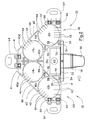
- the two modules 18 and 20 of the reservoir 12 are mounted vertically at an angle to each other, so as not to be arranged in the same plane and so that the reservoir 12 has a V-shaped section.
- external 22 and 28 face each other and the inner ducts 24 and 26 face each other.
- Each module 18, 20 comprises an inner side 46 and an outer side 48, the inner sides 46 facing each other and delimiting an internal space 50 between the modules 18 and 20 while the outer sides 48 are exposed to the sun's rays.
- the internal space 50 is closed by a plate 52 extending over the entire length of the tank 12, so that the shower 10 has a triangular cross section.
- the outer conduits 22 and 28 and inner 24 and 26 are of completely circular cross section.
- the cold water and hot water channels 32 each have a substantially triangular cross section and have an outer side 54 and an inner side 56 forming a substantially straight angle and an arcuate edge 58 whose curvature coincides with the curvature of the duct. external 22, 28 with which they are associated.
- the outer sides 54 of the two channels 30 and 32 are in the extension of each other along the direction A while the inner sides 56 are parallel and facing one another.
- the outer conduits 22 and 28 of the reservoir 12 comprise two sets of fins 42 of thermal conduction, each set being disposed on one side exposed to the sun's rays, while the inner conduits 24 and 26 each comprise a set of fins 42, disposed on the only side of this conduit 24, 26 which is exposed to sunlight.
- Each of the modules 18 and 20 also comprises four reservoirs 40 intended to store the heat transfer element, as explained above.
- Two of these tanks, referenced 40a and 40b, of flared triangular cross section, are arranged between the two ducts of the module 18, 20, respectively inner side 46 and outer side 48, the outer side tank 40b 48 comprising an aligned base 60 with the Alignment direction A fins 42.
- the two other tanks 40c and 40d are disposed on a portion of the side wall of the inner conduit 26, 24, respectively in the inner space 50 delimited by the two modules 18 and 20 and outer side 48.
- the two modules 18, 20 are extruded in the same profile and one 18 of the modules 18, 20 is mounted against the other module 20 by pivoting the profile by an angle of 180 ° in a vertical plane.
- one 18 of the modules 18, 20 is mounted head to tail relative to the other module 20.
- the reservoir 12 comprises an inner conduit 62 disposed in the internal space 50 between the two modules 18 and 20 and whose role is to supply water to the knob 16 of the shower 10.
- the valve 14 is partially embedded in the internal space 50.
- each module 18, 20 is screwed to ground fastening tabs 64 and comprises, close to the outer conduit 22, 28 two recesses 66 for each receiving a screw, and close to the internal conduit 24 , 26, a recess 66 for receiving a screw.
- the modules 18 and 20 are arranged in the same plane and aligned horizontally in a direction X , each duct 22 to 28 and channel 30, 32, being directed vertically, and delimit a front face 68 of the shower 10 on which are fixed the pommel 16 and the valve 14, and a rear face 70.
- the inner conduits 24 and 26 and outer 22 and 28 have a partially circular section, as described above.
- the inner conduits 26, 24 and outer 28, 22 of each module 18, 20 are secured to each other by a portion of their respective lateral wall, substantially flat and forming internal junction 72.
- Each duct 22 to 28 is provided with two sets of fins 42 facing each other and respectively disposed on the front face 68 and on the rear face 70 of the tank 12, the directions A of alignment of the outer ends. each set being parallel to the X direction.
- connection channels 30 and 32 of the reservoir 12 are disposed on the front face 68 of the reservoir 12 and in the extension of one another.
- the reservoir 12 also comprises a channel 74 for circulating water from the valve 14 to the shower head 16 of the shower 10, this channel 74 being disposed between the internal conduits 24 and 26 of the reservoir 12 , aligned with the channels of cold water 30 and hot water 32 of the tank 12 and parallel to these channels 30 and 32.
- the shower 10 comprises three storage tanks 40a, 40b and 40c of the heat transfer element, each of these tanks being on the rear face 70 of the aligned modules, and substantially facing the cold water channel 30, the circulation channel 74 towards the pommel 16 and the hot water channel 32.
- the reservoir 12 comprises three pairs of channels 30, 40a, 74, 40b, and 32, 40c, the channels of a pair being arranged facing each other and on the one hand and on the other hand. other of a plane P comprising the vertical direction Y and the alignment direction X of the modules 18 and 20, the connection channels 30, 32 and 74 of the modules 18, 20 to the shower 10 being those of the channels arranged on the front side 68 of the shower 10.
- the two modules 18 and 20 are extruded in the same profile and one 18 of the modules 18, 20 is mounted against the other module 20 by pivoting the profile by an angle of 180 ° in a horizontal plane.
- each module 18, 20 is provided with three channels, respectively 30, 40a and 40b and 74, 40c and 32, a pair of channels, respectively 30, 40a and 32, 40c being disposed from and other external conduit 22, 28 and a channel 40b, 74 on the inner conduit 26, 24.
- this configuration ensures that, during the pivoting of the profile and the alignment of the modules, the three channels arranged on the front face are the connection channels to the valve and the knob, as explained above, while the other three channels are the storage tanks of the heat transfer element, as explained above.
- a single 24, 26 of the two inner conduits 24, 26 is provided with a channel, bringing to two only the number of tanks of the heat transfer element.
- the reservoir 12 is kept in equilibrium by a bracket 76 fixed on its rear face 70.
- Two sets of screws introduced into recesses 78, 80 respectively aligned on the front face 68 and the rear face 70 of the reservoir 12 allow to secure the plates 38 at the ends of the modules.
- the outer duct 22 of the first module 18 is pierced in its lower part with an orifice 82 intended to receive a nozzle of a pipe for supplying the reservoir 12 with cold water and the module 18 is pierced in its the upper part of an orifice 84 for the passage of water between the external duct 22 and the inner duct 26.
- the duct 26 is also pierced with several transfer orifices 88 so that water can circulate from one module to the other. other.
- the internal duct 24 of the second module 20 is pierced with orifices 90 situated opposite the orifices 88 for transferring the internal duct 26 of the first module 18, which effectively allows the water to be transferred from the first module 18 to the second module 20.
- the number of these transfer orifices and / or their diameters are set so that there is a continuity of physical quantities governing the flow of water between the two modules 18 and 20.
- the module 20 is pierced in its lower part with a hole 92 for the passage of water between the internal duct 24 and the external duct 28.
- This external duct 28 of the second module 20 comprises in its upper part an outlet orifice 96 of hot water.
- the outer conduit 28 of the second module 20 is pierced in its upper part facing the inner conduit of an orifice 98 which allows a recirculation of water in the second module 20, ensuring a warmer water, longer.
- This orifice 98 is of a diameter smaller than the diameter of the orifice 92.
- the module 18 comprises in the lower part a bore between the pipe 22 and the cold water channel 30 which directly feeds the cold water tap of the Valve 14.
- the module 20 comprises in the upper part a bore between the duct 28 and the hot water channel 32, disposed opposite the discharge orifice 96, so that the channel 32 supplies the hot water faucet .
- the supply channel of the shower head is traversed by the water at temperature. intermediate, chosen by the user through the mixer tap 14 or mixer, and up to the shower head 16 of the shower 10 through which the water flows out of the tank 12.
- connection channels allows the taps to remain horizontal while being fed with both cold water and hot water.
- the module comprises channels adjacent to the ducts on which foggers may be attached.
- each duct is provided with fins, but it is sufficient that at least one duct 22, 26, 24, 28 of at least one module 18, 20 of the reservoir 12 comprises on a part of its sidewall of such fins 42.
Landscapes
- Engineering & Computer Science (AREA)
- Physics & Mathematics (AREA)
- Life Sciences & Earth Sciences (AREA)
- Sustainable Development (AREA)
- Sustainable Energy (AREA)
- Thermal Sciences (AREA)
- Chemical & Material Sciences (AREA)
- Combustion & Propulsion (AREA)
- Mechanical Engineering (AREA)
- General Engineering & Computer Science (AREA)
- Bathtubs, Showers, And Their Attachments (AREA)
Priority Applications (1)
| Application Number | Priority Date | Filing Date | Title |
|---|---|---|---|
| EP08305808A EP2186459A1 (de) | 2008-11-18 | 2008-11-18 | Solardusche |
Applications Claiming Priority (1)
| Application Number | Priority Date | Filing Date | Title |
|---|---|---|---|
| EP08305808A EP2186459A1 (de) | 2008-11-18 | 2008-11-18 | Solardusche |
Publications (1)
| Publication Number | Publication Date |
|---|---|
| EP2186459A1 true EP2186459A1 (de) | 2010-05-19 |
Family
ID=40512537
Family Applications (1)
| Application Number | Title | Priority Date | Filing Date |
|---|---|---|---|
| EP08305808A Withdrawn EP2186459A1 (de) | 2008-11-18 | 2008-11-18 | Solardusche |
Country Status (1)
| Country | Link |
|---|---|
| EP (1) | EP2186459A1 (de) |
Cited By (2)
| Publication number | Priority date | Publication date | Assignee | Title |
|---|---|---|---|---|
| CN108580069A (zh) * | 2017-12-29 | 2018-09-28 | 重庆新康洁具有限责任公司 | 淋浴喷头结构 |
| FR3077625A1 (fr) * | 2018-02-02 | 2019-08-09 | Fabrice Curt | Reservoir solaire universel pour colonne de douche |
Citations (3)
| Publication number | Priority date | Publication date | Assignee | Title |
|---|---|---|---|---|
| US4624242A (en) * | 1985-08-13 | 1986-11-25 | Examplar | Solar heat transfer and storage system |
| EP1142523A2 (de) * | 2000-04-06 | 2001-10-10 | Peter Diener | Solarthermische Duschvorrichtung zum Aufstellen im Freien |
| FR2908503A1 (fr) * | 2006-11-10 | 2008-05-16 | Laurent Prudet | Dispositif de stockage et de chauffage par energie solaire integrant un dispositif de circulation de l'eau melangeant et rechauffant l'eau froide |
-
2008
- 2008-11-18 EP EP08305808A patent/EP2186459A1/de not_active Withdrawn
Patent Citations (3)
| Publication number | Priority date | Publication date | Assignee | Title |
|---|---|---|---|---|
| US4624242A (en) * | 1985-08-13 | 1986-11-25 | Examplar | Solar heat transfer and storage system |
| EP1142523A2 (de) * | 2000-04-06 | 2001-10-10 | Peter Diener | Solarthermische Duschvorrichtung zum Aufstellen im Freien |
| FR2908503A1 (fr) * | 2006-11-10 | 2008-05-16 | Laurent Prudet | Dispositif de stockage et de chauffage par energie solaire integrant un dispositif de circulation de l'eau melangeant et rechauffant l'eau froide |
Cited By (2)
| Publication number | Priority date | Publication date | Assignee | Title |
|---|---|---|---|---|
| CN108580069A (zh) * | 2017-12-29 | 2018-09-28 | 重庆新康洁具有限责任公司 | 淋浴喷头结构 |
| FR3077625A1 (fr) * | 2018-02-02 | 2019-08-09 | Fabrice Curt | Reservoir solaire universel pour colonne de douche |
Similar Documents
| Publication | Publication Date | Title |
|---|---|---|
| EP2185046B1 (de) | Heisswasserbereiter für eine getränkezubereitungsmaschine | |
| EP2931093B1 (de) | Heisswasserbereiter für getränkezubereitungsautomat | |
| FR2912428A1 (fr) | Appareil de repassage comportant un cordon de vapeur muni d'un connecteur rotatif | |
| FR2912429A1 (fr) | Appareil de repassage a vapeur comportant un reservoir d'eau en communication directe avec une chambre d'ebullition | |
| EP2186459A1 (de) | Solardusche | |
| EP1155271B1 (de) | Plattenwärmetauscher mit integriertem ventil | |
| EP0148695B1 (de) | Solarwassererhitzer mit direktem Wasserdurchgang und Verfahren zu seiner Herstellung | |
| WO2008099265A1 (fr) | Appareil de repassage comportant une chambre d'ebullition dans laquelle la vapeur produite peut s'echapper librement vers un organe de repassage | |
| EP2251612A1 (de) | Elektrisches Heizgerät mit Wärmeübertragungsflüssigkeit, das aus gegossenen Modulelementen besteht | |
| FR2774459A1 (fr) | Corps de chauffe pour une chaudiere au fioul ou au gaz et modules pour la realisation d'un tel corps de chauffe | |
| WO2005083332A1 (fr) | Radiateur electrique a fluide caloporteur | |
| WO2010092247A1 (fr) | Chauffage solaire | |
| FR2782379A1 (fr) | Echangeur de chaleur | |
| EP4046273B1 (de) | Anlage mit einem verbinder zur fluidverbindung eines wärmetauschers von mindestens einem hybriden solarpaneel | |
| EP2034264B1 (de) | Baumartiger Heizkörper zum Trocknen von Handtüchern mit optimierter Flüssigkeitszirkulation | |
| EP1881942B1 (de) | Spendevorrichtung zur bereitstellung von gekühltem wasser | |
| FR3075350B1 (fr) | Radiateur a fluide caloporteur avec distribution uniforme de chaleur en facade | |
| EP4311983A1 (de) | Elektrischer heizkörper mit seitlichem elektrischem anschluss | |
| EP0201541A1 (de) | Vorrichtung für einen wasch- oder gartenschlauch zur erzeugung von warmwasser mittels sonnenenergie sowie zum aufwickeln, transportieren und leichten verstauen dieses schlauches | |
| FR2855250A1 (fr) | Unite de vanne de chauffage | |
| FR2520851A1 (fr) | Appareil de chauffage de fluide a partir de l'energie solaire | |
| FR2976348A1 (fr) | Canne d'injection de liquide et systeme de stockage utilisant une telle canne | |
| FR2958827A1 (fr) | Corps de chauffe electrique | |
| FR2902503A1 (fr) | Radiateur a fluide caloporteur | |
| FR3083303A1 (fr) | Radiateur a elements radiants integrant un separateur d'ecoulement |
Legal Events
| Date | Code | Title | Description |
|---|---|---|---|
| PUAI | Public reference made under article 153(3) epc to a published international application that has entered the european phase |
Free format text: ORIGINAL CODE: 0009012 |
|
| AK | Designated contracting states |
Kind code of ref document: A1 Designated state(s): AT BE BG CH CY CZ DE DK EE ES FI FR GB GR HR HU IE IS IT LI LT LU LV MC MT NL NO PL PT RO SE SI SK TR |
|
| AX | Request for extension of the european patent |
Extension state: AL BA MK RS |
|
| AKY | No designation fees paid | ||
| REG | Reference to a national code |
Ref country code: DE Ref legal event code: 8566 |
|
| STAA | Information on the status of an ep patent application or granted ep patent |
Free format text: STATUS: THE APPLICATION IS DEEMED TO BE WITHDRAWN |
|
| 18D | Application deemed to be withdrawn |
Effective date: 20101120 |