EP2185950B1 - Einfügung von positionsinformationen für oberflächen in einer geologischen formation nach deren umwandlung in eine gespaltene darstellung - Google Patents
Einfügung von positionsinformationen für oberflächen in einer geologischen formation nach deren umwandlung in eine gespaltene darstellung Download PDFInfo
- Publication number
- EP2185950B1 EP2185950B1 EP08829744.5A EP08829744A EP2185950B1 EP 2185950 B1 EP2185950 B1 EP 2185950B1 EP 08829744 A EP08829744 A EP 08829744A EP 2185950 B1 EP2185950 B1 EP 2185950B1
- Authority
- EP
- European Patent Office
- Prior art keywords
- gap
- well
- wells
- geological formation
- unconformity
- Prior art date
- Legal status (The legal status is an assumption and is not a legal conclusion. Google has not performed a legal analysis and makes no representation as to the accuracy of the status listed.)
- Not-in-force
Links
- 230000015572 biosynthetic process Effects 0.000 title claims description 38
- 230000001131 transforming effect Effects 0.000 title 1
- 238000000034 method Methods 0.000 claims description 50
- 230000000007 visual effect Effects 0.000 claims description 8
- 238000005553 drilling Methods 0.000 claims description 6
- 230000004044 response Effects 0.000 claims description 6
- 239000000126 substance Substances 0.000 claims description 6
- 238000012545 processing Methods 0.000 claims description 5
- 239000000463 material Substances 0.000 claims description 4
- 230000008021 deposition Effects 0.000 claims description 3
- 230000003628 erosive effect Effects 0.000 claims description 3
- 239000011435 rock Substances 0.000 claims 6
- 230000009466 transformation Effects 0.000 claims 1
- 230000004048 modification Effects 0.000 description 8
- 238000012986 modification Methods 0.000 description 8
- 238000010586 diagram Methods 0.000 description 5
- 230000008569 process Effects 0.000 description 5
- 108020005351 Isochores Proteins 0.000 description 4
- 239000003550 marker Substances 0.000 description 4
- 241001048293 Isopaches Species 0.000 description 3
- 230000009471 action Effects 0.000 description 3
- 230000008901 benefit Effects 0.000 description 3
- 238000004891 communication Methods 0.000 description 3
- 239000004065 semiconductor Substances 0.000 description 3
- 238000002347 injection Methods 0.000 description 2
- 239000007924 injection Substances 0.000 description 2
- 238000013459 approach Methods 0.000 description 1
- 230000003190 augmentative effect Effects 0.000 description 1
- 239000003245 coal Substances 0.000 description 1
- 238000000205 computational method Methods 0.000 description 1
- 230000003247 decreasing effect Effects 0.000 description 1
- 230000002708 enhancing effect Effects 0.000 description 1
- 239000007789 gas Substances 0.000 description 1
- 229910052500 inorganic mineral Inorganic materials 0.000 description 1
- 239000011707 mineral Substances 0.000 description 1
- 239000003921 oil Substances 0.000 description 1
- 230000003287 optical effect Effects 0.000 description 1
- 238000005192 partition Methods 0.000 description 1
- 239000011275 tar sand Substances 0.000 description 1
- 230000007704 transition Effects 0.000 description 1
Images




Classifications
-
- G—PHYSICS
- G01—MEASURING; TESTING
- G01V—GEOPHYSICS; GRAVITATIONAL MEASUREMENTS; DETECTING MASSES OR OBJECTS; TAGS
- G01V99/00—Subject matter not provided for in other groups of this subclass
Definitions
- the present invention generally relates to the field of interpretive earth modeling, and more particularly, to a system, method and memory medium for the injection of additional points onto surfaces of a geological formation.
- a geological formation includes a number of layers.
- the boundaries between the layers are referred to herein as surfaces.
- Wells may be drilled into the geological formation in order to gather information about the layers and the surfaces between them. In particular, samples of position on the surfaces may be determined. Because the drilling of wells is expensive, the number of surface sample points that can be gathered in a geological formation is limited. Thus, some of the surfaces may be not be sampled sufficiently densely to allow an accurate estimation of the surfaces.
- Surfaces may be estimated with surface models. Some surfaces may be under-constrained, i.e., not constrained with a sufficient number of surface sample points to allow an accurate estimation of the surface.
- the surface sample points on a given surface may be interpreted as constraints on a modeling algorithm that attempts to estimate the surface with a model.
- the existing methods for handling the under-constrained surface problem (using isochore or isopach maps) are cumbersome.
- An isochore map may be added to a given surface in order to extrapolate an under-constrained (e.g., partially missing or spatially limited) surface into a fault or unconformity.
- the extrapolated surface may then be the basis for the addition of another isochore map to extrapolate yet another surface into the fault or unconformity, and so on.
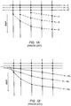
- the modeling algorithm operates on the surface sample points for a given surface and creates a model for the surface.
- the quality of the surface model depends in part on the number of surface sample points for that surface as suggested in Figure 1B .
- Models M A , M B and M C approximate surfaces A, B and C respectively.
- model M C poorly represents surface C.
- a consideration of the laws of geoscience would not suggest that surface C should be as flat as model M C suggests.
- Geoscience laws suggest that formation tops tend to parallel other surface tops. Therefore M c should be parallel to M A .
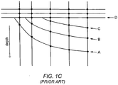
- Figure 1C represents the geologist's conception of how the surfaces should behave.
- the geologist looks at surface A as a guide and concludes that all the surfaces (i.e., surfaces A, B and C) are sub-parallel and are likely folded and truncated below the lowest subhorizontal surface (i.e., surface D).
- the predominant method for effectively modeling surfaces B and C involves first building isopach (or isochore) maps between the most well-constrained surface (surface A) and the less well-constrained surfaces (surfaces B and C), and then successively adding these isopach maps starting from the most well-constrained surface. This method requires lots of manual bookkeeping, and, most significantly, requires that there be a well-constrained surface to use to constrain the less well-constrained surfaces. If such a surface does not exist there is no simple way to model the less well-constrained surfaces.
- US patent 4,991,095 A concerns a process for three-dimensional mathematical modelling of underground geologic volumes.
- the process uses a stored program processor for modelling a geologic volume which has inclined, stacked layers of sedimentary deposits.
- a computer-implemented method for enhancing the quality of modeling of surfaces in a geological formation involves the following operations.
- a computer receives user input selecting a subset S of wells from a collection of wells.
- the computer displays a cross section of the geological formation through the wells of the subset S.
- the displayed cross section includes well picks for the wells of the subset S.
- the computer modifies a geological data set to open a gap in an unconformity of the displayed cross section.
- the gap is opened at one or more wells of the subset S that intersect the unconformity.
- the gap represents non-deposition and/or material that is missing from the geological formation due to erosion.
- the computer receives user input specifying positions of tops within the gap.
- the computer modifies the geological data set to close the gap in response to a user command.
- the action of closing the gap includes calculating positions of restored tops based on the positions of the tops specified within the gap.
- the positions of the restored tops are usable to model one or more surfaces in the geological formation.
- the displayed cross section is continually updated on the display as the computer operates to modify the geological data set to open and/or close the gap.
- the computer display provides a continuously updated visual representation of the cross section of the geological formation as the computer opens / closes the gap, in order to visually display these operations to a user.
- the computer may store the positions of the restored tops in a memory medium.
- this computer-implemented method may be repeated for any or all of the unconformities. Furthermore, this computer-implemented method may be repeated for any number of well subsets.
- the computer may be programmed to operate on well picks corresponding to the collection of wells and on the restored top positions in order to determine one or more models for one or more surfaces in the geological formation.
- the computer may be able to do a better job at generating models that accurately estimate the formation surfaces since it has access to the extra information provided by the restored top positions.
- the surface models may be used to estimate a location of a substance (i.e., an economically valuable substance) in the geological formation.
- the estimated location may be used to control a drilling of a well, control the acquisition of seismic data, determine a policy for exploitation of the substance, etc.
- the computer may display a visual representation of the geological formation including a representation of the one or more surface models.
- the computer may also visually update the visual representation as various of the computer operations are performed on the geological data set (including opening and/or closing of gaps) as described herein.
- a computer-accessible memory medium is configured to store program instructions, where the program instructions are executable to implement any of the method embodiments described herein (or, any combination of the method embodiments described herein, or, any subset of any method embodiment described herein).
- a memory medium is a medium configured for the storage of information. Examples of memory media include various kinds of magnetic media (e.g., magnetic tape, magnetic disk, magnetic strips, and magnetic film); various kinds of optical media (e.g., CD-ROM); various kinds of semiconductor RAM and ROM; various media based on the storage of electrical charge and/or other physical quantities; etc.
- a system according to claim 15 is configured to include a processor (or a set of processors) and memory medium.
- the memory medium is configured to store program instructions.
- the processor is configured to read and execute the program instructions.
- the program instructions are executable to implement any of the various method embodiments described herein (or, any combination of the method embodiments described herein, or, any subset of the method embodiments described herein).
- the computer system may be realized in any of various forms.
- the computer system may be a personal computer (in any of its various forms), a workstation, a computer on a card, a server computer, a client computer, etc.
- a set of computers distributed through a network may be configured to partition the effort of executing a method (e.g., any of the method embodiments disclosed herein).
- a computer-implemented method for operating on a geological data set may involve the following operations, as illustrated in Figure 2 .
- the computer-implemented method comprises displaying information corresponding to the geological data set, e.g., displaying a cross section of the geological formation.
- the computer-implemented method further comprises continually or interactively updating the display based on actions performed by the computer to modify the data set, including opening and/or closing gaps in the cross section of the geological formation.
- a computer receives user input selecting a subset S of the wells from the collection C.
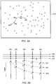
- the computer displays a window 210 containing a two-dimensional plot of well positions in a field, as illustrated in Figure 3A .
- the window illustrates well positions as seen looking down on the field.
- the user selects wells by clicking on (or otherwise identifying) the positions of the wells in the window on the display.
- the user input specifies an ordered sequence of wells. While the example of Figure 3A shows a sequence of five wells (W1 through W5) that have been selected by a user, any number of wells may be selected.
- the computer displays a window showing a cross section of the geological formation through the wells of the subset S, as suggested in Figure 3B .
- the displayed cross section includes a visual representation of the well picks for the wells of subset S. (In Figure 3B , the well picks are represented by round dots.)
- a "well pick" is an estimate of a point along a well trajectory where one layer transitions into another layer.
- Figure 3B illustrates boundaries 301-306 which are boundaries between layers.
- Well picks A, D and G correspond to boundary 303.
- Well picks B, E, H and J correspond to boundary 302.
- Well picks C, F, I, K and L correspond to boundary 301.
- One or more unconformities may be present in the displayed cross section.
- Figure 5 shows one unconformity starting approximately at point P and extending to the left along boundary 304.
- An unconformity is an interface between layers that represents a discontinuity in geological time.
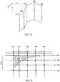
- FIG. 3B may be interpreted as a flattened-out representation of a folded plane. Imagine the folded plane as cutting vertically into the earth and being folded at the well locations of the subset.
- Figure 4 illustrates the folded plane for the subset of five wells given in Figure 3A .
- the computer modifies the geological data set to open a gap in an unconformity of the displayed cross section.
- the gap is opened at one or more wells of the subset S that intersect the unconformity.
- the gap represents non-deposition and/or material that is missing from the geological formation due to erosion.
- the computer updates the display of the cross section in response to the modification of the geological data set to open the gap, e.g., continuously and/or interactively update the cross section as the modification to open the gap is performed.
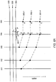
- the gap may be opened in stages, e.g., one well at a time as suggested in Figures 6A-6D .
- Figure 6A shows a first stage in which the gap is initially opened along well W4. (Any of the wells that intersect the unconformity could have been used to open the gap.
- Well W4 is chosen here merely for the sake of discussion.)
- the gap is opened up in the downward direction by an amount ⁇ z 4 specified by the user.
- the gap is illustrated in cross-hatch.
- each of the well picks along well W4 and below the unconformity is translated vertically downward by the same amount ⁇ z 4 (which may be illustrated on the computer display).
- the well picks originally at positions D, E and F are translated respectively to positions D', E' and F'.
- the user specifies the amount ⁇ z 4 by dragging on a marker m (denoted with a small square icon) that indicates the bottom edge of the gap.
- Figure 6A illustrates the situation where the user has selected amount ⁇ z 4 so that the translated positions D', E' and F' line up at the same depths as the corresponding well picks on well W5, i.e., with well picks A, B and C.
- this condition of alignment of well picks of one well with those of another may not be achievable since a given layer may not have a uniform thickness (in the depth dimension) at each of the wells.
- Figure 6B illustrates a second stage in which the gap is extended to including an opening along well W3.
- the user specifies an amount ⁇ z 3 by which the gap is be opened.
- each of the well picks along well W3 and below the unconformity is translated downward by the same amount ⁇ z 3 (which may be illustrated on the computer display).
- the well picks originally at positions G, H and I are translated respectively to positions G', H' and I'.
- the user may specify the amount ⁇ z 3 by dragging on a marker (not shown) that indicates the bottom edge of the gap (i.e., that portion of the gap being opened up along well W3).
- Figure 6C illustrates a third stage in which the gap is extended to including an opening along well W2.
- the user specifies an amount ⁇ z 2 by which the gap is be opened.
- each of the well picks along well W2 and below the unconformity is translated downward by the same amount ⁇ z 2 .
- the well picks originally at positions J and K are translated respectively to positions J' and K'.
- the user may specify the amount ⁇ z 2 by dragging on a marker m (denoted with a small square icon) that indicates the bottom edge of the gap (i.e., that portion of the gap being opened up along well W2).
- Figure 6D illustrates a fourth stage in which the gap is extended to including an opening along well W1.
- the user specifies an amount ⁇ z 1 by which the gap is be opened.
- each of the well picks along well W1 and below the unconformity is translated downward by the same amount ⁇ z 1 (which may be illustrated on the computer display).
- the well pick originally at position L is translated to position L'.
- the user may specify the amount ⁇ z 1 by dragging on a marker m (denoted with a small square icon) that indicates the bottom edge of the gap (i.e., that portion of the gap being opened up along well W1).
- Figure 6D shows each of the modified boundaries 301-4, 302-4 and 303-4 as being a locus of constant depth.
- a diagram is said to be pseudo-Wheeler diagram when this condition is achieved for all the boundaries between layers in a diagram. (Such a diagram is said to have been transformed to "pseudo Wheeler space”.) As discussed above, this condition is not achievable in general because layers generally vary in thickness from one well to the next. However, it is noted that the embodiments disclosed herein do not require that this condition be achieved.
- step 125 may be performed.
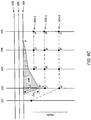
- the computer may receive user input specifying the positions of tops within the gap, e.g., as suggested by the tops T1-T3 (denoted by small "x" symbols) in Figure 7 .
- the computer may update (e.g., continuously update) the display of the cross section in response to the user input specifying the top positions.
- each of the tops is specified on one of the wells. Tops T1 and T2 have been specified along well W1, and top T3 has been specified on well W2. Furthermore, each of the tops is specified at a position that is consistent with one of the boundaries in the displayed diagram. For example, tops T1 and T3 are specified at positions that are consistent with boundary 503, and top T2 is specified at a position that is consistent with boundary 502. The fact that the boundaries 502 and 503 have been flattened into loci of constant depth (in the illustrated example) by the gap-opening process of step 120 makes it easy for a user to estimate appropriate locations for the tops T1-T3.
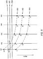
- the computer may modify the geological data set to close the gap, e.g., as suggested in Figure 8 .
- the computer may update the display of the cross section in response to the modification of the geological data set to close the gap, e.g., continuously and/or interactively update the cross section as the modification to close the gap is performed.
- the action of closing the gap includes calculating positions of restored tops based on the positions of the corresponding tops within the gap.
- Figure 8 illustrates restored tops R1, R2 and R3 which correspond to tops T1, T2 and T3 respectively.
- the positions of the restored tops may be used to improve the modeling of surfaces in the geological formation.
- the positions of restored tops R1 and R3 may be added to a data set including well picks A, D and G to improve the modeling of boundary 303 (or, the modeling of a surface of which boundary 303 is portion) in the geological formation.
- restored top position R2 may be added to a data set including well picks B, E, H and J to improve the modeling of boundary 302.
- the displayed cross section may include more than one unconformity.
- steps 120 and 125 may be repeated for one or more additional unconformities in the displayed cross section.
- Figure 3B illustrates the situation where a number of layers (e.g., the layers between boundaries 301-303) meet an unconformity from below.
- the unconformity bounds those layers from above.
- the gap is opened up by translating well picks underneath the unconformity in a downward direction (i.e., the direction of increasing depth).
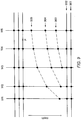
- an unconformity may bound a set of layers from below as suggested in Figure 9 .
- the gap would be opened up by translating well picks above the unconformity in the upward direction (i.e., the direction of decreasing depth).
- Figure 2 is described in terms a single set of wells. However, the steps of Figure 2 may be repeated for any number of well subsets.
- the restored tops generated by the above-described method may be used to augment the well pick positions of wells in collection C.
- the augmented data set may be supplied to a surface modeling routine.
- the surface modeling routine can do a better job at generating models that accurately estimate the surfaces in the formation. Any of various known surface modeling routines are contemplated for use in generating the surface models.
- the surface models may be used to estimate a location of a substance in the geological formation using the one or more surface models, e.g., a substance such as oil, gas, tar sand, coal, any of various minerals, etc.
- the estimated location may be used to control the drilling of a well, e.g., to determine a surface location to initiate drilling of the well or to determine the well plan of the well.
- the estimated location may be used to control the acquisition of seismic data, to determine placement of geophones and sensors, etc.
- the computer may be configured (with appropriate software) to display a visual representation of the geological formation including a visual depiction of one or more of the surface models.
- the visual representation of the geological formation may be updated interactively (e.g., in real time) as user input is received and/or modifications are made to the data set (e.g., to open or close gaps).
- the method embodiment of Figure 2 is implemented as an extension to SmartSECTION®, a software product available from Halliburton Energy Services.
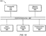
- FIG. 10 illustrates one embodiment of a computer system 800.
- Computer system 800 may include a processing unit 810, a collection of memory devices 815, a communication bus 820, a set of input devices 825, and one or more display devices 830.
- the collection of memory devices 815 may include any of various forms of memory media and memory access devices.
- memory devices 815 may include semiconductor RAM and ROM devices as well as mass storage devices such as CD-ROM drives, magnetic disk drives, magnetic tape drives, storage area networks (SANs), etc.
- Processing unit 810 is configured to read and execute program instructions, e.g., program instructions stored on a memory medium such as a set of one or more CD-ROMs, and loaded into semiconductor memory at execution time. Processing unit 810 may couple to memory devices 815 through communication bus 820 (or through a collection of busses). The program instructions configure the computer system 800 to implement a method, e.g., any of the method embodiments described herein (or any combination of the methods described herein or any subset of any method described herein).
- Processing unit 810 may include one or more programmable processors (e.g., microprocessors).
- One or more users may supply input to the system 800 through the set of input devices 825.
- Input devices 825 may include devices such as keyboards, mouse devices, digitizing pads, track balls, light pens, data gloves, eye orientation sensors, head orientation sensors, etc.
- the set of display devices 830 may include devices such as monitors, projectors, head-mounted displays, printers, plotters, etc.
- system 800 may include one or more communication devices 835, e.g., a network interface card for interfacing with a computer network. For example, a collection of surface sample points obtained at a remote computer may be transmitted to the system 800 through a computer network. The system 800 may receive the collection of surface sample points from the computer network using the network interface card. In other embodiments, the system 800 may include a plurality of computers and/or other components coupled over the computer network.
- communication devices 835 e.g., a network interface card for interfacing with a computer network.
- a collection of surface sample points obtained at a remote computer may be transmitted to the system 800 through a computer network.
- the system 800 may receive the collection of surface sample points from the computer network using the network interface card.
- the system 800 may include a plurality of computers and/or other components coupled over the computer network.
Landscapes
- Physics & Mathematics (AREA)
- Life Sciences & Earth Sciences (AREA)
- General Life Sciences & Earth Sciences (AREA)
- General Physics & Mathematics (AREA)
- Geophysics (AREA)
- Investigation Of Foundation Soil And Reinforcement Of Foundation Soil By Compacting Or Drainage (AREA)
- Geophysics And Detection Of Objects (AREA)
- Management, Administration, Business Operations System, And Electronic Commerce (AREA)
- Consolidation Of Soil By Introduction Of Solidifying Substances Into Soil (AREA)
Claims (15)
- Computerimplementiertes Verfahren zum Arbeiten an einem Satz geologischer Daten, der Bohrlochmarker für eine Anzahl von Bohrlöchern in einer geologischen Formation beinhaltet, wobei das Verfahren Folgendes umfasst:(a) Speichern des Satzes geologischer Daten auf einem Speichermedium;(b) Empfangen (110) einer Benutzereingabe zur Auswahl einer Untergruppe der Bohrlöcher;(c) Anzeigen (115) eines Querschnitts der geologischen Formation durch die Bohrlöcher der Untergruppe auf einer Anzeige, wobei der angezeigte Querschnitt Bohrlochmarker für die Bohrlöcher der Untergruppe beinhaltet;gekennzeichnet durch folgende weitere Schritte:(d) Modifizieren (120) des Satzes geologischer Daten, um einen Spalt in einer Ungleichförmigkeit des angezeigten Querschnitts zu öffnen, wobei der Spalt an einem oder mehreren Bohrlöchern der Untergruppe geöffnet wird, die die Ungleichförmigkeit schneiden, wobei der Spalt Nichtablagerung und/oder Material darstellt, das aufgrund von Erosion in der geologischen Formation fehlt;(e) Empfangen (125) einer Benutzereingabe zur Angabe von Positionen der Oberseiten (T1, T2, T3) in dem Spalt; und(f) Modifizieren (130) des Satzes geologischer Daten, um den Spalt zu schließen, wobei das Schließen des Spalts das Berechnen von Positionen wiederhergestellter Oberseiten (R1, R2, R3) auf Grundlage der Positionen der Oberseiten in dem Spalt umfasst;wobei die Positionen der wiederhergestellten Oberseiten verwendbar sind, um eine oder mehrere Oberflächen in der geologischen Formation zu modellieren, und dadurch beim Steuern des Bohrens eines Bohrlochs in der geologischen Formation verwendbar sind.
- Verfahren nach Anspruch 1, wobei das Anzeigen des Querschnitts auf der Anzeige in Reaktion auf das Modifizieren des Satzes geologischer Daten, um den Spalt zu öffnen, und in Reaktion auf das Modifizieren des Satzes geologischer Daten, um den Spalt zu schließen, aktualisiert wird.
- Verfahren nach einem der vorhergehenden Ansprüche, wobei die geologische Formation eine Anzahl von Felsschichten beinhaltet, wobei die Bohrlochmarker der Anzahl von Bohrlöchern Positionsproben auf Oberflächen zwischen den Felsschichten darstellen, wobei das Öffnen des Spalts eine Transformation des angezeigten Querschnitts in einen Pseudo-Wheeler-Raum bewirkt.
- Verfahren nach einem der vorhergehenden Ansprüche, wobei die geologische Formation eine Anzahl von Felsschichten beinhaltet, wobei die Bohrlochmarker der Anzahl von Bohrlöchern Positionsproben auf Oberflächen zwischen den Felsschichten darstellen, wobei die Bohrlochmarker, die den einzelnen Oberflächen entsprechen, nach dem Öffnen des Spalts horizontal ausgerichtet werden.
- Verfahren nach einem der vorhergehenden Ansprüche, ferner umfassend:Wiederholen von (b) bis (f) für eine andere Untergruppe der Bohrlöcher.
- Verfahren nach einem der vorhergehenden Ansprüche, ferner umfassend:Wiederholen von (d) für eine weitere Ungleichförmigkeit in dem angezeigten Querschnitt.
- Verfahren nach den vorhergehenden Ansprüchen,
wobei die geologische Formation eine Anzahl von Felsschichten beinhaltet, wobei die Bohrlochmarker der Anzahl von Bohrlöchern Positionsproben auf Oberflächen zwischen den Felsschichten darstellen,
wobei das Verfahren ferner umfasst:Arbeiten an den Bohrlochmarkern der Anzahl von Bohrlöchern und an den Positionen der wiederhergestellten Oberseiten, um jeweils ein oder mehrere Oberflächenmodelle für eine oder mehrere Oberflächen zu bestimmen. - Verfahren nach einem der vorhergehenden Ansprüche, wobei (d) Folgendes beinhaltet:(d1) Empfangen einer vierten Benutzereingabe zur Auswahl eines ersten Bohrlochs, das die Ungleichförmigkeit schneidet;(d2) Verschieben von einem oder mehreren Bohrlochmarkern, die dem ausgewählten Bohrloch entsprechen und sich unter der Ungleichförmigkeit befinden, wobei das Verschieben den einen oder die mehreren Bohrlochmarker in dem angezeigten Querschnitt um eine Größe vertikal nach unten bewegt, die durch eine fünfte Benutzereingabe bestimmt wird.
- Verfahren nach Anspruch 8, ferner umfassend:Durchführen von (d1) und (d2) für ein oder mehrere weitere Bohrlöcher, die die Ungleichförmigkeit schneiden.
- Verfahren nach einem der vorhergehenden Ansprüche, ferner umfassend:Schätzen eines Ortes einer Substanz in der geologischen Formation mithilfe von dem einen oder den mehreren Oberflächenmodellen.
- Verfahren nach Anspruch 10, ferner umfassend:Verwenden des geschätzten Ortes zum Steuern des Bohrens des Bohrlochs.
- Verfahren nach Anspruch 10, ferner umfassend:Anzeigen einer visuellen Darstellung der geologischen Formation mit einer Darstellung des einen oder der mehreren Oberflächenmodelle auf der Anzeige.
- Verfahren nach einem der vorhergehenden Ansprüche, ferner umfassend:Speichern der Positionen der wiederhergestellten Oberseiten auf einem Speichermedium.
- Computerlesbares Speichermedium, das Programmanweisungen speichert, die dazu angepasst sind, die einzelnen Schritte der Verfahren nach einem der Ansprüche 1-13 auszuführen.
- System (800), umfassend eine Verarbeitungseinheit (810), einen Satz Eingabevorrichtungen (825) und eine oder mehrere Anzeigevorrichtungen (830), wobei das System (800) dazu angepasst ist, die einzelnen Schritte der Verfahren nach einem der Ansprüche 1-13 umzusetzen.
Applications Claiming Priority (3)
| Application Number | Priority Date | Filing Date | Title |
|---|---|---|---|
| US96986007P | 2007-09-04 | 2007-09-04 | |
| US12/186,225 US8265914B2 (en) | 2007-09-04 | 2008-08-05 | Adding positional information for surfaces in a geological formation after transforming to a gapped representation |
| PCT/US2008/075144 WO2009032857A2 (en) | 2007-09-04 | 2008-09-03 | Adding positional information for surfaces in a geological formation after transforming to a gapped representation |
Publications (2)
| Publication Number | Publication Date |
|---|---|
| EP2185950A2 EP2185950A2 (de) | 2010-05-19 |
| EP2185950B1 true EP2185950B1 (de) | 2017-03-01 |
Family
ID=40408817
Family Applications (1)
| Application Number | Title | Priority Date | Filing Date |
|---|---|---|---|
| EP08829744.5A Not-in-force EP2185950B1 (de) | 2007-09-04 | 2008-09-03 | Einfügung von positionsinformationen für oberflächen in einer geologischen formation nach deren umwandlung in eine gespaltene darstellung |
Country Status (10)
| Country | Link |
|---|---|
| US (1) | US8265914B2 (de) |
| EP (1) | EP2185950B1 (de) |
| CN (1) | CN102132172B (de) |
| AU (1) | AU2008296280B2 (de) |
| BR (1) | BRPI0816407A2 (de) |
| CA (1) | CA2698372C (de) |
| EA (1) | EA017209B1 (de) |
| EG (1) | EG26308A (de) |
| MX (1) | MX2010002522A (de) |
| WO (1) | WO2009032857A2 (de) |
Families Citing this family (3)
| Publication number | Priority date | Publication date | Assignee | Title |
|---|---|---|---|---|
| AU2008349520B2 (en) * | 2008-01-28 | 2010-11-25 | Landmark Graphics Corporation | Hybrid stratigraphic layering using pseudo-wheeler space |
| GB2486877B (en) * | 2010-12-21 | 2018-02-07 | Statoil Petroleum As | Quality control of sub-surface and wellbore position data |
| CN118886617B (zh) * | 2024-09-29 | 2024-12-13 | 四川嘉阳集团有限责任公司 | 一种薄煤层工作面开采地质条件综合评估方法 |
Family Cites Families (11)
| Publication number | Priority date | Publication date | Assignee | Title |
|---|---|---|---|---|
| US4357660A (en) * | 1973-05-01 | 1982-11-02 | Schlumberger Technology Corporation | Formation dip and azimuth processing technique |
| US4414656A (en) * | 1980-04-15 | 1983-11-08 | Schlumberger Technology Corporation | Well logging system for mapping structural and sedimentary dips of underground earth formations |
| US4638254A (en) * | 1983-05-02 | 1987-01-20 | Mobil Oil Corporation | Method of determining and displaying the orientation of subsurface formations |
| US4821164A (en) * | 1986-07-25 | 1989-04-11 | Stratamodel, Inc. | Process for three-dimensional mathematical modeling of underground geologic volumes |
| US4781062A (en) * | 1987-10-23 | 1988-11-01 | Amoco Corporation | Conjugate fracture systems and formation stresses in subterranean formations |
| FR2641889B1 (fr) * | 1989-01-18 | 1991-03-29 | Schlumberger Prospection | Procede de representation graphique polychrome du pendage des couches geologiques |
| US5363299A (en) * | 1993-06-14 | 1994-11-08 | Marathon Oil Company | Method for identifying faults and unconformities in a geologic formation |
| US6012017A (en) * | 1996-09-25 | 2000-01-04 | Geoquest, A Division Of Schlumberger Technology Corporation | Interpreting formation tops |
| RU2223521C2 (ru) * | 1997-12-01 | 2004-02-10 | Шлюмбергер Текнолоджи Б.В. | Способ и устройство для создания, проверки и модификации геологических моделей подповерхностных зон |
| US6853922B2 (en) * | 2001-07-20 | 2005-02-08 | Tracy Joseph Stark | System for information extraction from geologic time volumes |
| EP1766439A2 (de) * | 2004-07-01 | 2007-03-28 | ExxonMobil Upstream Research Company | Auf hydrodynamik basierendes geologisches gridding-modellieren (hydro-gridding) |
-
2008
- 2008-08-05 US US12/186,225 patent/US8265914B2/en not_active Expired - Fee Related
- 2008-09-03 EA EA201000291A patent/EA017209B1/ru not_active IP Right Cessation
- 2008-09-03 AU AU2008296280A patent/AU2008296280B2/en not_active Ceased
- 2008-09-03 WO PCT/US2008/075144 patent/WO2009032857A2/en not_active Ceased
- 2008-09-03 EP EP08829744.5A patent/EP2185950B1/de not_active Not-in-force
- 2008-09-03 BR BRPI0816407A patent/BRPI0816407A2/pt not_active IP Right Cessation
- 2008-09-03 MX MX2010002522A patent/MX2010002522A/es active IP Right Grant
- 2008-09-03 CN CN200880105535.8A patent/CN102132172B/zh not_active Expired - Fee Related
- 2008-09-03 CA CA2698372A patent/CA2698372C/en not_active Expired - Fee Related
-
2010
- 2010-03-04 EG EG2010030359A patent/EG26308A/en active
Non-Patent Citations (1)
| Title |
|---|
| None * |
Also Published As
| Publication number | Publication date |
|---|---|
| CN102132172A (zh) | 2011-07-20 |
| EA017209B1 (ru) | 2012-10-30 |
| CN102132172B (zh) | 2014-11-05 |
| US8265914B2 (en) | 2012-09-11 |
| AU2008296280A1 (en) | 2009-03-12 |
| CA2698372A1 (en) | 2009-03-12 |
| EP2185950A2 (de) | 2010-05-19 |
| WO2009032857A2 (en) | 2009-03-12 |
| BRPI0816407A2 (pt) | 2019-09-24 |
| EG26308A (en) | 2013-07-15 |
| US20090063117A1 (en) | 2009-03-05 |
| AU2008296280B2 (en) | 2013-09-05 |
| CA2698372C (en) | 2014-01-21 |
| WO2009032857A3 (en) | 2010-11-04 |
| EA201000291A1 (ru) | 2011-02-28 |
| MX2010002522A (es) | 2010-05-24 |
Similar Documents
| Publication | Publication Date | Title |
|---|---|---|
| EP2359304B1 (de) | Bildung eines modells einer unterirdischen region | |
| EP3298437B1 (de) | Inversion für tektonische beanspruchung | |
| EP2491516B1 (de) | Optimierungsverfahren mit gradienteninformationen | |
| EP2539740B1 (de) | Systeme und verfahren zur modellierung dreidimensionaler geographischer strukturen | |
| CN101617101B (zh) | 井和泄流位置的自动化油田开发方案 | |
| US11953637B2 (en) | Methods and systems of generating simulation grids for different structural interpretations | |
| CN103975341B (zh) | 基于4d饱和度模型和仿真模型的储层建模 | |
| US9733391B2 (en) | Method and system for geophysical modeling of subsurface volumes | |
| CA2793811A1 (en) | System and method for performing oilfield drilling operations using visualization techniques | |
| RU2601232C2 (ru) | Способы и системы для включения мест выделенных точек псевдоповерхности в модели скорости сейсмических волн | |
| EP2185950B1 (de) | Einfügung von positionsinformationen für oberflächen in einer geologischen formation nach deren umwandlung in eine gespaltene darstellung | |
| EP2756447B1 (de) | Systeme und verfahren für unterstützte eigenschaftsmodellierung | |
| Silalahi et al. | Advancing Steamflood Performance Through a New Integrated Optimization Process: Transform the Concept into Practical | |
| Castiñeira et al. | Automated identification of optimal deviated and horizontal well targets | |
| Gulbrandsen et al. | Automatic mapping of the base of aquifer—A case study from Morrill, Nebraska | |
| Selveindran et al. | Smart custom well design based on automated offset well analysis | |
| Tan et al. | Unveiling FDP Breakthroughs and Innovations: Transforming Brownfield Rejuvenation Strategies for Infill Drilling Delivery Through Agile Reservoir Modeling and Integrated Technical Assessment | |
| Kansao et al. | Intelligent and automated workflow for identification of behind pipe recompletions and new infill locations opportunities for an onshore middle east field | |
| US9354340B2 (en) | Strike and dip tooltip for seismic sections | |
| Uland et al. | 3-D reservoir characterization for improved reservoir management | |
| Al-Jaberi et al. | Real-Time 3D modeling and geosteering in a heterogeneous carbonate reservoir | |
| Ndokwu et al. | Reservoir Navigation in Njaba Field–Challenges, Procedure and Results | |
| EP3999882B1 (de) | Verformung von bohrlochbahnen | |
| Maas et al. | The Impact of Smart Completions on Optimal Well Trajectories | |
| Raja et al. | Workflows and Methods to Optimize Well Construction through a Collaborative Environment |
Legal Events
| Date | Code | Title | Description |
|---|---|---|---|
| PUAI | Public reference made under article 153(3) epc to a published international application that has entered the european phase |
Free format text: ORIGINAL CODE: 0009012 |
|
| 17P | Request for examination filed |
Effective date: 20100304 |
|
| AK | Designated contracting states |
Kind code of ref document: A2 Designated state(s): AT BE BG CH CY CZ DE DK EE ES FI FR GB GR HR HU IE IS IT LI LT LU LV MC MT NL NO PL PT RO SE SI SK TR |
|
| R17D | Deferred search report published (corrected) |
Effective date: 20101104 |
|
| DAX | Request for extension of the european patent (deleted) | ||
| REG | Reference to a national code |
Ref country code: DE Ref legal event code: R079 Ref document number: 602008048986 Country of ref document: DE Free format text: PREVIOUS MAIN CLASS: G01V0011000000 Ipc: G01V0099000000 |
|
| RIC1 | Information provided on ipc code assigned before grant |
Ipc: G01V 99/00 20090101AFI20160530BHEP |
|
| GRAP | Despatch of communication of intention to grant a patent |
Free format text: ORIGINAL CODE: EPIDOSNIGR1 |
|
| INTG | Intention to grant announced |
Effective date: 20160927 |
|
| GRAS | Grant fee paid |
Free format text: ORIGINAL CODE: EPIDOSNIGR3 |
|
| GRAA | (expected) grant |
Free format text: ORIGINAL CODE: 0009210 |
|
| AK | Designated contracting states |
Kind code of ref document: B1 Designated state(s): AT BE BG CH CY CZ DE DK EE ES FI FR GB GR HR HU IE IS IT LI LT LU LV MC MT NL NO PL PT RO SE SI SK TR |
|
| REG | Reference to a national code |
Ref country code: GB Ref legal event code: FG4D |
|
| REG | Reference to a national code |
Ref country code: CH Ref legal event code: EP Ref country code: AT Ref legal event code: REF Ref document number: 872003 Country of ref document: AT Kind code of ref document: T Effective date: 20170315 |
|
| REG | Reference to a national code |
Ref country code: IE Ref legal event code: FG4D |
|
| REG | Reference to a national code |
Ref country code: DE Ref legal event code: R096 Ref document number: 602008048986 Country of ref document: DE |
|
| REG | Reference to a national code |
Ref country code: NO Ref legal event code: T2 Effective date: 20170301 |
|
| REG | Reference to a national code |
Ref country code: NL Ref legal event code: MP Effective date: 20170301 |
|
| REG | Reference to a national code |
Ref country code: LT Ref legal event code: MG4D |
|
| REG | Reference to a national code |
Ref country code: AT Ref legal event code: MK05 Ref document number: 872003 Country of ref document: AT Kind code of ref document: T Effective date: 20170301 |
|
| REG | Reference to a national code |
Ref country code: FR Ref legal event code: PLFP Year of fee payment: 10 |
|
| PG25 | Lapsed in a contracting state [announced via postgrant information from national office to epo] |
Ref country code: GR Free format text: LAPSE BECAUSE OF FAILURE TO SUBMIT A TRANSLATION OF THE DESCRIPTION OR TO PAY THE FEE WITHIN THE PRESCRIBED TIME-LIMIT Effective date: 20170602 Ref country code: LT Free format text: LAPSE BECAUSE OF FAILURE TO SUBMIT A TRANSLATION OF THE DESCRIPTION OR TO PAY THE FEE WITHIN THE PRESCRIBED TIME-LIMIT Effective date: 20170301 Ref country code: HR Free format text: LAPSE BECAUSE OF FAILURE TO SUBMIT A TRANSLATION OF THE DESCRIPTION OR TO PAY THE FEE WITHIN THE PRESCRIBED TIME-LIMIT Effective date: 20170301 Ref country code: FI Free format text: LAPSE BECAUSE OF FAILURE TO SUBMIT A TRANSLATION OF THE DESCRIPTION OR TO PAY THE FEE WITHIN THE PRESCRIBED TIME-LIMIT Effective date: 20170301 |
|
| PG25 | Lapsed in a contracting state [announced via postgrant information from national office to epo] |
Ref country code: ES Free format text: LAPSE BECAUSE OF FAILURE TO SUBMIT A TRANSLATION OF THE DESCRIPTION OR TO PAY THE FEE WITHIN THE PRESCRIBED TIME-LIMIT Effective date: 20170301 Ref country code: SE Free format text: LAPSE BECAUSE OF FAILURE TO SUBMIT A TRANSLATION OF THE DESCRIPTION OR TO PAY THE FEE WITHIN THE PRESCRIBED TIME-LIMIT Effective date: 20170301 Ref country code: BG Free format text: LAPSE BECAUSE OF FAILURE TO SUBMIT A TRANSLATION OF THE DESCRIPTION OR TO PAY THE FEE WITHIN THE PRESCRIBED TIME-LIMIT Effective date: 20170601 Ref country code: LV Free format text: LAPSE BECAUSE OF FAILURE TO SUBMIT A TRANSLATION OF THE DESCRIPTION OR TO PAY THE FEE WITHIN THE PRESCRIBED TIME-LIMIT Effective date: 20170301 Ref country code: AT Free format text: LAPSE BECAUSE OF FAILURE TO SUBMIT A TRANSLATION OF THE DESCRIPTION OR TO PAY THE FEE WITHIN THE PRESCRIBED TIME-LIMIT Effective date: 20170301 |
|
| PG25 | Lapsed in a contracting state [announced via postgrant information from national office to epo] |
Ref country code: NL Free format text: LAPSE BECAUSE OF FAILURE TO SUBMIT A TRANSLATION OF THE DESCRIPTION OR TO PAY THE FEE WITHIN THE PRESCRIBED TIME-LIMIT Effective date: 20170301 |
|
| PG25 | Lapsed in a contracting state [announced via postgrant information from national office to epo] |
Ref country code: RO Free format text: LAPSE BECAUSE OF FAILURE TO SUBMIT A TRANSLATION OF THE DESCRIPTION OR TO PAY THE FEE WITHIN THE PRESCRIBED TIME-LIMIT Effective date: 20170301 Ref country code: IT Free format text: LAPSE BECAUSE OF FAILURE TO SUBMIT A TRANSLATION OF THE DESCRIPTION OR TO PAY THE FEE WITHIN THE PRESCRIBED TIME-LIMIT Effective date: 20170301 Ref country code: SK Free format text: LAPSE BECAUSE OF FAILURE TO SUBMIT A TRANSLATION OF THE DESCRIPTION OR TO PAY THE FEE WITHIN THE PRESCRIBED TIME-LIMIT Effective date: 20170301 Ref country code: EE Free format text: LAPSE BECAUSE OF FAILURE TO SUBMIT A TRANSLATION OF THE DESCRIPTION OR TO PAY THE FEE WITHIN THE PRESCRIBED TIME-LIMIT Effective date: 20170301 Ref country code: CZ Free format text: LAPSE BECAUSE OF FAILURE TO SUBMIT A TRANSLATION OF THE DESCRIPTION OR TO PAY THE FEE WITHIN THE PRESCRIBED TIME-LIMIT Effective date: 20170301 |
|
| PG25 | Lapsed in a contracting state [announced via postgrant information from national office to epo] |
Ref country code: PL Free format text: LAPSE BECAUSE OF FAILURE TO SUBMIT A TRANSLATION OF THE DESCRIPTION OR TO PAY THE FEE WITHIN THE PRESCRIBED TIME-LIMIT Effective date: 20170301 Ref country code: IS Free format text: LAPSE BECAUSE OF FAILURE TO SUBMIT A TRANSLATION OF THE DESCRIPTION OR TO PAY THE FEE WITHIN THE PRESCRIBED TIME-LIMIT Effective date: 20170701 Ref country code: PT Free format text: LAPSE BECAUSE OF FAILURE TO SUBMIT A TRANSLATION OF THE DESCRIPTION OR TO PAY THE FEE WITHIN THE PRESCRIBED TIME-LIMIT Effective date: 20170703 |
|
| REG | Reference to a national code |
Ref country code: DE Ref legal event code: R097 Ref document number: 602008048986 Country of ref document: DE |
|
| PLBE | No opposition filed within time limit |
Free format text: ORIGINAL CODE: 0009261 |
|
| STAA | Information on the status of an ep patent application or granted ep patent |
Free format text: STATUS: NO OPPOSITION FILED WITHIN TIME LIMIT |
|
| PG25 | Lapsed in a contracting state [announced via postgrant information from national office to epo] |
Ref country code: DK Free format text: LAPSE BECAUSE OF FAILURE TO SUBMIT A TRANSLATION OF THE DESCRIPTION OR TO PAY THE FEE WITHIN THE PRESCRIBED TIME-LIMIT Effective date: 20170301 |
|
| 26N | No opposition filed |
Effective date: 20171204 |
|
| PG25 | Lapsed in a contracting state [announced via postgrant information from national office to epo] |
Ref country code: SI Free format text: LAPSE BECAUSE OF FAILURE TO SUBMIT A TRANSLATION OF THE DESCRIPTION OR TO PAY THE FEE WITHIN THE PRESCRIBED TIME-LIMIT Effective date: 20170301 |
|
| REG | Reference to a national code |
Ref country code: DE Ref legal event code: R119 Ref document number: 602008048986 Country of ref document: DE |
|
| REG | Reference to a national code |
Ref country code: CH Ref legal event code: PL |
|
| PG25 | Lapsed in a contracting state [announced via postgrant information from national office to epo] |
Ref country code: MC Free format text: LAPSE BECAUSE OF FAILURE TO SUBMIT A TRANSLATION OF THE DESCRIPTION OR TO PAY THE FEE WITHIN THE PRESCRIBED TIME-LIMIT Effective date: 20170301 |
|
| REG | Reference to a national code |
Ref country code: IE Ref legal event code: MM4A |
|
| REG | Reference to a national code |
Ref country code: BE Ref legal event code: MM Effective date: 20170930 |
|
| PG25 | Lapsed in a contracting state [announced via postgrant information from national office to epo] |
Ref country code: LU Free format text: LAPSE BECAUSE OF NON-PAYMENT OF DUE FEES Effective date: 20170903 |
|
| REG | Reference to a national code |
Ref country code: FR Ref legal event code: PLFP Year of fee payment: 11 |
|
| PG25 | Lapsed in a contracting state [announced via postgrant information from national office to epo] |
Ref country code: LI Free format text: LAPSE BECAUSE OF NON-PAYMENT OF DUE FEES Effective date: 20170930 Ref country code: DE Free format text: LAPSE BECAUSE OF NON-PAYMENT OF DUE FEES Effective date: 20180404 Ref country code: IE Free format text: LAPSE BECAUSE OF NON-PAYMENT OF DUE FEES Effective date: 20170903 Ref country code: CH Free format text: LAPSE BECAUSE OF NON-PAYMENT OF DUE FEES Effective date: 20170930 |
|
| PG25 | Lapsed in a contracting state [announced via postgrant information from national office to epo] |
Ref country code: BE Free format text: LAPSE BECAUSE OF NON-PAYMENT OF DUE FEES Effective date: 20170930 |
|
| PG25 | Lapsed in a contracting state [announced via postgrant information from national office to epo] |
Ref country code: MT Free format text: LAPSE BECAUSE OF NON-PAYMENT OF DUE FEES Effective date: 20170903 |
|
| PG25 | Lapsed in a contracting state [announced via postgrant information from national office to epo] |
Ref country code: HU Free format text: LAPSE BECAUSE OF FAILURE TO SUBMIT A TRANSLATION OF THE DESCRIPTION OR TO PAY THE FEE WITHIN THE PRESCRIBED TIME-LIMIT; INVALID AB INITIO Effective date: 20080903 |
|
| PG25 | Lapsed in a contracting state [announced via postgrant information from national office to epo] |
Ref country code: CY Free format text: LAPSE BECAUSE OF NON-PAYMENT OF DUE FEES Effective date: 20170301 |
|
| PGFP | Annual fee paid to national office [announced via postgrant information from national office to epo] |
Ref country code: FR Payment date: 20190927 Year of fee payment: 12 Ref country code: NO Payment date: 20190826 Year of fee payment: 12 |
|
| PGFP | Annual fee paid to national office [announced via postgrant information from national office to epo] |
Ref country code: GB Payment date: 20190703 Year of fee payment: 12 |
|
| PG25 | Lapsed in a contracting state [announced via postgrant information from national office to epo] |
Ref country code: TR Free format text: LAPSE BECAUSE OF FAILURE TO SUBMIT A TRANSLATION OF THE DESCRIPTION OR TO PAY THE FEE WITHIN THE PRESCRIBED TIME-LIMIT Effective date: 20170301 |
|
| REG | Reference to a national code |
Ref country code: NO Ref legal event code: MMEP |
|
| GBPC | Gb: european patent ceased through non-payment of renewal fee |
Effective date: 20200903 |
|
| PG25 | Lapsed in a contracting state [announced via postgrant information from national office to epo] |
Ref country code: FR Free format text: LAPSE BECAUSE OF NON-PAYMENT OF DUE FEES Effective date: 20200930 Ref country code: NO Free format text: LAPSE BECAUSE OF NON-PAYMENT OF DUE FEES Effective date: 20200930 |
|
| PG25 | Lapsed in a contracting state [announced via postgrant information from national office to epo] |
Ref country code: GB Free format text: LAPSE BECAUSE OF NON-PAYMENT OF DUE FEES Effective date: 20200903 |