EP2185397B1 - Transportation unit for a cable transportation system, and cable transportation system comprising such a unit - Google Patents
Transportation unit for a cable transportation system, and cable transportation system comprising such a unit Download PDFInfo
- Publication number
- EP2185397B1 EP2185397B1 EP08786655A EP08786655A EP2185397B1 EP 2185397 B1 EP2185397 B1 EP 2185397B1 EP 08786655 A EP08786655 A EP 08786655A EP 08786655 A EP08786655 A EP 08786655A EP 2185397 B1 EP2185397 B1 EP 2185397B1
- Authority
- EP
- European Patent Office
- Prior art keywords
- transportation unit
- transportation
- cable
- chair
- trolley
- Prior art date
- Legal status (The legal status is an assumption and is not a legal conclusion. Google has not performed a legal analysis and makes no representation as to the accuracy of the status listed.)
- Active
Links
Images

Classifications
-
- B—PERFORMING OPERATIONS; TRANSPORTING
- B61—RAILWAYS
- B61B—RAILWAY SYSTEMS; EQUIPMENT THEREFOR NOT OTHERWISE PROVIDED FOR
- B61B12/00—Component parts, details or accessories not provided for in groups B61B7/00 - B61B11/00
- B61B12/04—Devices for damping vibrations
-
- B—PERFORMING OPERATIONS; TRANSPORTING
- B61—RAILWAYS
- B61B—RAILWAY SYSTEMS; EQUIPMENT THEREFOR NOT OTHERWISE PROVIDED FOR
- B61B12/00—Component parts, details or accessories not provided for in groups B61B7/00 - B61B11/00
- B61B12/002—Cabins; Ski-lift seats
Definitions
- the present invention relates to a transportation unit for a cable transportation system.
- the present invention relates to a transportation unit which is moved in a travelling direction and comprises a suspension arm; a trolley connected to the suspension arm and which engages a rail at a turnaround station of the cable transportation system; and a chair connected to the suspension arm.
- Transportation units of the above type are used for passenger transport, and the chair extends in width predominantly crosswise to the travelling direction.
- transportation units now have a much larger capacity than in the past. More specifically, chair-lift chairs have gradually become wider and wider, to the point of now comprising eight seats in a row crosswise to the travelling direction.
- This operating condition of the cable transportation system is acceptable up to a certain degree of tilt of the transportation unit, but becomes a problem when the transportation unit is detached from the cable, and the trolley engages a rail and is driven by an auxiliary drive device at the turnaround station.
- the trolley engages the rail at relatively high speed, and, despite the lead-in of the rail, engagement produces a sharp change in the tilt angle of the transportation unit, including the chair, which is a major source of discomfort to passengers.
- document FR 2,197,363 , EP 1,342 , 635 , EP 1,151 , 903 , and EP 1,640,235 suggests arranging an articulated joint assembly between the chair and the trolley.
- the present invention also relates to a cable transportation system
- Number 1 in Figure 1 indicates as a whole a cable transportation system comprising a cable 2 extending along an endless path; a number of transportation units 3 (only one shown in Figure 1 ); and two turnaround stations 4 (only one shown in Figure 1 ).
- Turnaround station 4 comprises a rail 5 with three linear cams 6, 7, 8 extending along a given path; and a drive device (not shown) for driving transportation units 3 inside turnaround station 4.
- Each transportation unit 3 is moved in a travelling direction D1 by cable 2 along the path portions between the two turnaround stations 4, and by the drive device (not shown) along the path portions at turnaround stations 4.
- Each transportation unit 3 extends in width crosswise to travelling direction D1.
- transportation unit 3 is shown being detached from cable 2, and engages rail 5 at turnaround station 4.
- Each transportation unit 3 comprises a suspension arm 9; a trolley 10 connected to suspension arm 9 and supporting a clamp 11 for selectively engaging cable 2 (as shown more clearly in Figures 2 and 3 ); a chair 12; and an articulated joint assembly 13 between chair 12 and trolley 10.
- suspension arm 9 is connected rigidly to trolley 10, but is hinged to chair 12 about an axis A1 parallel to travelling direction D1 of transportation unit 3 and crosswise to the width of transportation unit 3.
- Chair 12 comprises an inverted-U-shaped frame 14; a seat 15; a backrest 16; a safety bar 17 which rotates about an axis A2; and four footrest assemblies 18 fixed to safety bar 17.
- chair 12 has eight seats in a row, and is substantially symmetrical with respect to a plane of symmetry P.
- articulated joint assembly 13 is located between chair 12 and suspension arm 9, but may be located anywhere between chair 12 and trolley 10, e.g. between two portions of suspension arm 9.
- Articulated joint assembly 13 comprises a pin 19 extending along axis A1; a flange 20 fixed to suspension arm 9; a flange 21 fixed to frame 14 of chair 12; a coil spring 22 between suspension arm 9 and frame 14 of chair 12; and a shock absorber 23 between suspension arm 9 and frame 14 of chair 12.
- shock absorber 23 is located inside coil spring 22.
- articulated joint assembly 13 can be locked selectively in a given position by means of a lock device 30. More specifically, shock absorber 23 between chair 12 and trolley 10 can be locked in a given position to lock articulated joint assembly 13 as a whole.
- shock absorber 23 is a fluid shock absorber comprising a cylinder 24; and a piston 25 which slides inside cylinder 24 and divides cylinder 24 into two chambers 26, 27 communicating via a connecting circuit 28 with a constriction 29.
- lock device 30 selectively locks shock absorber 23 and communication between chambers 26 and 27, and comprises a two-way valve 31 maintained in a normally-open position by a spring 32; and a Bowden cable 33 for overcoming the force of spring 32 (as shown schematically in Figure 4 ).
- lock device 30 comprises a lever 34, which is connected to Bowden cable 33, is hinged to suspension arm 9, and is operated by a linear cam 35.
- chair 12 moves into a horizontal position, and articulated joint assembly 13 is locked by lock device 30 to lock chair 12 with respect to suspension arm 9 in a substantially horizontal position, and keep chair 12 in this position, even after the passengers have boarded, along the rest of the path at turnaround station 4.
- articulated joint assembly 13 is locked along the path portion at turnaround station 4 extending between the passenger-alighting portion and the exit of turnaround station 4.
- the articulated joint assembly is locked before the passengers alight.
- transportation unit 3 is equipped with a lock device 36, and moves along a cable system 1 in which linear cam 35 is replaced by an electrically conductive strip 37.
- lock device 36 comprises a sliding electric contact 38, an electric cable 39, and a two-position, two-way, normally-open solenoid valve 40 respectively.
- solenoid valve 40 is controlled by an electric signal transmitted via strip 37, sliding electric contact 38, and electric cable 39.
- transportation unit 3 comprises, instead of shock absorber 23, a rubber silentblock-type shock absorber 41; and, instead of lock device 30, a lock device 42 comprising linear cam 35, lever 34, Bowden cable 33, a brake clamp 43 connected to the suspension arm, and a rod 44 connected to chair 12 - in the example shown, to frame 14 of chair 12 - and engaged by brake clamp 43.
- Bowden cable 33 provides for closing the normally-open brake clamp 43, and for gripping rod 44 to lock chair 12 in a given position with respect to suspension arm 9.
Landscapes
- Engineering & Computer Science (AREA)
- Transportation (AREA)
- Mechanical Engineering (AREA)
- Electric Cable Arrangement Between Relatively Moving Parts (AREA)
- Seats For Vehicles (AREA)
Description
- The present invention relates to a transportation unit for a cable transportation system.
- More specifically, the present invention relates to a transportation unit which is moved in a travelling direction and comprises a suspension arm; a trolley connected to the suspension arm and which engages a rail at a turnaround station of the cable transportation system; and a chair connected to the suspension arm.
- Transportation units of the above type are used for passenger transport, and the chair extends in width predominantly crosswise to the travelling direction. As a result of the tendency in the passenger cable transportation industry to increase passenger-carrying capacity per unit of time, transportation units now have a much larger capacity than in the past. More specifically, chair-lift chairs have gradually become wider and wider, to the point of now comprising eight seats in a row crosswise to the travelling direction.
- While indeed increasing chair-lift carrying capacity, chairs with a large number of seats have the drawback that, when the chair is occupied only partly by a small number of passengers, and asymmetrically with respect to the cable, the entire transportation unit rotates about the cable into a tilted position.
- This operating condition of the cable transportation system is acceptable up to a certain degree of tilt of the transportation unit, but becomes a problem when the transportation unit is detached from the cable, and the trolley engages a rail and is driven by an auxiliary drive device at the turnaround station.
- The trolley engages the rail at relatively high speed, and, despite the lead-in of the rail, engagement produces a sharp change in the tilt angle of the transportation unit, including the chair, which is a major source of discomfort to passengers.
- In order to eliminate the drawbacks of the known art, document
FR 2,197,363 EP 1,342 635 EP 1,151 903 EP 1,640,235 suggests arranging an articulated joint assembly between the chair and the trolley. - The shift in the position of the trolley from the ideal position with respect to the rail is thus reduced, thus reducing the intensity of any shock or sharp movements transmitted to the chair.
- However the swinging movement of the chair may cause problem in the turnaround station in particular when all passenger do not seat simultaneously on the chair.
- It is an object of the present invention to provide a transportation unit of the above-identified type that is free from the above mentioned problem.
- According to the present invention there is provided a transportation unit according to claim 1.
- The present invention also relates to a cable transportation system
- According to the present invention, there is provided a cable transportation system according to
claim 12. - A non-limiting embodiment of the present invention will be described by way of example with reference to the accompanying drawings, in which:
-
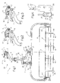
Figure 1 shows a partly sectioned front view, with parts removed for clarity, of a cable transportation system; -
Figures 2 and 3 show larger-scale, partly sectioned front views, with parts removed for clarity, of a detail of the cable transportation system at two different operating stages; -
Figure 4 shows a larger-scale, partly sectioned schematic of a lock device of theFigure 1 transportation unit; -
Figure 5 shows a schematic of a variation of the lock device; -
Figure 6 shows a schematic of a further variation of the lock device. - Number 1 in
Figure 1 indicates as a whole a cable transportation system comprising acable 2 extending along an endless path; a number of transportation units 3 (only one shown inFigure 1 ); and two turnaround stations 4 (only one shown inFigure 1 ). - Turnaround
station 4 comprises arail 5 with threelinear cams transportation units 3 insideturnaround station 4. - Each
transportation unit 3 is moved in a travelling direction D1 bycable 2 along the path portions between the twoturnaround stations 4, and by the drive device (not shown) along the path portions atturnaround stations 4. - Each
transportation unit 3 extends in width crosswise to travelling direction D1. InFigure 1 ,transportation unit 3 is shown being detached fromcable 2, and engagesrail 5 atturnaround station 4. Eachtransportation unit 3 comprises asuspension arm 9; atrolley 10 connected tosuspension arm 9 and supporting aclamp 11 for selectively engaging cable 2 (as shown more clearly inFigures 2 and 3 ); achair 12; and an articulatedjoint assembly 13 betweenchair 12 andtrolley 10. In other words,suspension arm 9 is connected rigidly totrolley 10, but is hinged tochair 12 about an axis A1 parallel to travelling direction D1 oftransportation unit 3 and crosswise to the width oftransportation unit 3. -
Chair 12 comprises an inverted-U-shaped frame 14; aseat 15; abackrest 16; asafety bar 17 which rotates about an axis A2; and fourfootrest assemblies 18 fixed tosafety bar 17. In theFigure 1 example,chair 12 has eight seats in a row, and is substantially symmetrical with respect to a plane of symmetry P. - In the
Figure 1 example, articulatedjoint assembly 13 is located betweenchair 12 andsuspension arm 9, but may be located anywhere betweenchair 12 andtrolley 10, e.g. between two portions ofsuspension arm 9. -
Articulated joint assembly 13 comprises apin 19 extending along axis A1; aflange 20 fixed tosuspension arm 9; aflange 21 fixed toframe 14 ofchair 12; acoil spring 22 betweensuspension arm 9 andframe 14 ofchair 12; and a shock absorber 23 betweensuspension arm 9 andframe 14 ofchair 12. - In the
Figure 1 example,shock absorber 23 is located insidecoil spring 22. - In one embodiment of the present invention, articulated
joint assembly 13 can be locked selectively in a given position by means of alock device 30. More specifically, shock absorber 23 betweenchair 12 andtrolley 10 can be locked in a given position to lock articulatedjoint assembly 13 as a whole. - As shown more clearly in
Figure 4 ,shock absorber 23 is a fluid shock absorber comprising a cylinder 24; and apiston 25 which slides inside cylinder 24 and divides cylinder 24 into twochambers circuit 28 with aconstriction 29. - With reference to
Figure 1 ,lock device 30 selectively locks shock absorber 23 and communication betweenchambers way valve 31 maintained in a normally-open position by aspring 32; and a Bowdencable 33 for overcoming the force of spring 32 (as shown schematically inFigure 4 ). - As shown in
Figure 1 ,lock device 30 comprises alever 34, which is connected to Bowdencable 33, is hinged tosuspension arm 9, and is operated by alinear cam 35. - In actual use, when occupied off-balance with respect to plane of symmetry P along the path portions between the two
turnaround stations 4,chair 12 rotates about axis A1 into a tilted position with respect to plane of symmetry P, so thatsuspension arm 9 andtrolley 10 are shifted slightly with respect to the ideal position (Figure 1 ). As the off-balance transportation unit 3 enters turnaroundstation 4,trolley 10 engagesrail 5 and produces shock, the degree of which depends on the deviation oftrolley 10 from its ideal position, but which is anyway absorbed bysuspension arm 9 and transmitted damped by articulatedjoint assembly 13 to prevent shock being transmitted tochair 12. - After the passengers alight and before other passengers board
transportation unit 3 at turnaroundstation 4,chair 12 moves into a horizontal position, and articulatedjoint assembly 13 is locked bylock device 30 to lockchair 12 with respect tosuspension arm 9 in a substantially horizontal position, and keepchair 12 in this position, even after the passengers have boarded, along the rest of the path atturnaround station 4. - In other words, articulated
joint assembly 13 is locked along the path portion atturnaround station 4 extending between the passenger-alighting portion and the exit ofturnaround station 4. - Alternatively, the articulated joint assembly is locked before the passengers alight.
- In the
Figure 5 variation,transportation unit 3 is equipped with alock device 36, and moves along a cable system 1 in whichlinear cam 35 is replaced by an electricallyconductive strip 37. Instead oflever 34, Bowdencable 33, andvalve 31,lock device 36 comprises a slidingelectric contact 38, anelectric cable 39, and a two-position, two-way, normally-open solenoid valve 40 respectively. - In this variation,
solenoid valve 40 is controlled by an electric signal transmitted viastrip 37, slidingelectric contact 38, andelectric cable 39. - In the
Figure 6 variation,transportation unit 3 comprises, instead of shock absorber 23, a rubber silentblock-type shock absorber 41; and, instead oflock device 30, alock device 42 comprisinglinear cam 35,lever 34, Bowdencable 33, abrake clamp 43 connected to the suspension arm, and a rod 44 connected to chair 12 - in the example shown, to frame 14 of chair 12 - and engaged bybrake clamp 43. - In this variation, Bowden
cable 33 provides for closing the normally-open brake clamp 43, and for gripping rod 44 to lockchair 12 in a given position with respect tosuspension arm 9.
Claims (12)
- A transportation unit for a cable transportation system (1) is moved in a travelling direction (D1) and comprises a suspension arm (9); a trolley (10) connected to the suspension arm (9) and which engages a rail (5) at a turnaround station (4) of the cable transportation system (1); a chair (12) connected to the suspension arm (9); and an articulated joint assembly (13) between the chair (12) and the trolley (10); the transportation unit being characterized by comprising a lock device (30; 36; 42) for locking the articulated joint assembly (13) and the chair (12) in a given position with respect to the trolley (10).
- A transportation unit as claimed in Claim 1, characterized in that the articulated joint assembly (13) comprises a hinge pin (19) substantially parallel to the travelling direction (D1).
- A transportation unit as claimed in Claim 2, characterized in that the articulated joint assembly (13) comprises a first and a second flange (20, 21) connected to each other by the hinge pin (19).
- A transportation unit as claimed in any one of Claims 1 to 3, characterized in that the articulated joint assembly (13) comprises an elastic member (22) between the chair (12) and the trolley (10).
- A transportation unit as claimed in any one of the foregoing Claims, characterized by comprising a shock absorber (23) between the chair (12) and the trolley (10).
- A transportation unit as claimed in Claim 5, characterized in that the shock absorber (23) is a fluid shock absorber comprising a cylinder (24); and a piston (25) dividing the cylinder into two communicating chambers (26, 27).
- A transportation unit as claimed in Claim 6, characterized in that the shock absorber (23) comprises a circuit (28) connecting the communicating chambers (26, 27) of the cylinder (24); the transportation unit (3) comprising a lock device (30; 36) in turn comprising a valve (31; 40) located along the circuit (28) to selectively open and close the circuit (28).
- A transportation unit as claimed in Claim 7, characterized in that the lock device (30; 36) comprises a spring (32) for keeping the valve (31; 40) open.
- A transportation unit as claimed in Claim 8, characterized in that the lock device (30) comprises a lever (34), which is activated by a linear cam (8) at the turnaround station (4) and is connected to the valve (31) by a mechanical transmission (34) to selectively close the valve (31) and to lock the articulated joint assembly (13) in a given position.
- A transportation unit as claimed in Claim 8, characterized in that said valve is a solenoid valve (40) ; the lock device (36) comprising an electric cable (39) connectable to a conductive strip (37) at the turnaround station (4) to transmit an opening signal to the solenoid valve (40).
- A transportation unit as claimed in any one of the claims from 1 to 4, characterized in that the lock device (42) comprises a brake clamp (43) which grips a rod (44) to lock said articulated joint assembly (13).
- A cable transportation system (1) comprising a cable extending along an endless path between two turnaround stations (4) to move, in a travelling direction (D1), a number of transportation units (3), each of which comprises a suspension arm (9); a trolley (10) connected to the suspension arm (9) and which engages a rail (5) at a turnaround station (4) of the cable transportation system (1); and a chair (12) connected to the suspension arm (9) ; the cable transportation system (1) being characterized in that each transportation unit (3) is configured as claimed in at least one of the foregoing claims.
Applications Claiming Priority (2)
| Application Number | Priority Date | Filing Date | Title |
|---|---|---|---|
| ITMI20071556 ITMI20071556A1 (en) | 2007-07-30 | 2007-07-30 | TRANSPORT UNIT FOR ROPE TRANSPORTATION SYSTEM AND ROPE TRANSPORTATION SYSTEM INCLUDING SUCH TRANSPORTATION UNIT |
| PCT/EP2008/060029 WO2009016211A1 (en) | 2007-07-30 | 2008-07-30 | Transportation unit for a cable transportation system, and cable transportation system comprising such a unit |
Publications (2)
| Publication Number | Publication Date |
|---|---|
| EP2185397A1 EP2185397A1 (en) | 2010-05-19 |
| EP2185397B1 true EP2185397B1 (en) | 2012-09-12 |
Family
ID=39952444
Family Applications (1)
| Application Number | Title | Priority Date | Filing Date |
|---|---|---|---|
| EP08786655A Active EP2185397B1 (en) | 2007-07-30 | 2008-07-30 | Transportation unit for a cable transportation system, and cable transportation system comprising such a unit |
Country Status (3)
| Country | Link |
|---|---|
| EP (1) | EP2185397B1 (en) |
| IT (1) | ITMI20071556A1 (en) |
| WO (1) | WO2009016211A1 (en) |
Families Citing this family (2)
| Publication number | Priority date | Publication date | Assignee | Title |
|---|---|---|---|---|
| CN102501856A (en) * | 2011-12-30 | 2012-06-20 | 北京起重运输机械设计研究院 | Suspension carriage swing prevention device for aerial cableway |
| IT201700036544A1 (en) * | 2017-04-03 | 2018-10-03 | Leitner Spa | STATION FOR A ROPE TRANSPORTATION SYSTEM, ROPE TRANSPORTATION SYSTEM INCLUDING SUCH STATION AND METHOD OF FUNCTIONING OF THIS ROPE TRANSPORTATION SYSTEM |
Family Cites Families (6)
| Publication number | Priority date | Publication date | Assignee | Title |
|---|---|---|---|---|
| US3170412A (en) * | 1963-05-06 | 1965-02-23 | Ribiet Tramway Company | Chair swing damper |
| FR2197363A5 (en) * | 1972-08-25 | 1974-03-22 | Montaz Mautino | |
| AT408873B (en) * | 2000-04-25 | 2002-03-25 | Innova Patent Gmbh | ARMCHAIR FOR A ROPEWAY SYSTEM |
| DE50203267D1 (en) * | 2002-03-07 | 2005-07-07 | Innova Patent Gmbh Wolfurt | Driving equipment, such as armchair or cabin, for a cable car, with swivel damper |
| ES2279501T3 (en) * | 2004-09-23 | 2007-08-16 | Innova Patent Gmbh | DEVICE FOR THE HOLDING OF A MEANS OF TRANSPORTATION OF A FUNCTIONAL INSTALLATION IN A SUSPENSION BAR. |
| ITBZ20050001A1 (en) * | 2005-01-11 | 2006-07-12 | High Technology Invest Bv | ROPE AIR TRANSPORT VEHICLE, IN PARTICULAR CHAIRS OF A CHAIRWAY. |
-
2007
- 2007-07-30 IT ITMI20071556 patent/ITMI20071556A1/en unknown
-
2008
- 2008-07-30 EP EP08786655A patent/EP2185397B1/en active Active
- 2008-07-30 WO PCT/EP2008/060029 patent/WO2009016211A1/en not_active Ceased
Also Published As
| Publication number | Publication date |
|---|---|
| EP2185397A1 (en) | 2010-05-19 |
| ITMI20071556A1 (en) | 2009-01-31 |
| WO2009016211A1 (en) | 2009-02-05 |
Similar Documents
| Publication | Publication Date | Title |
|---|---|---|
| EP2139741B1 (en) | Chair-lift | |
| CN101198506B (en) | Delivery facility for traveling body for transportation | |
| KR20160078432A (en) | System for transporting people | |
| US4957047A (en) | Cable transport installation | |
| US20100275809A1 (en) | Roller coaster | |
| EP2185397B1 (en) | Transportation unit for a cable transportation system, and cable transportation system comprising such a unit | |
| EP2655155B1 (en) | Cable transportation system with at least one haul cable and a trolley, and relative operating method | |
| CN101417622B (en) | Forward tiltable motor vehicle seat with hinge mountings | |
| KR20230000668A (en) | Ramp system of vehicle | |
| CN111629936B (en) | Two-stage safety device for bow-shaped rack | |
| EP1227964B1 (en) | In-vehicle switch mechanism | |
| ES2803900T3 (en) | Cableway installation | |
| CA2579666C (en) | Suspension conveyance apparatus | |
| JP6762699B2 (en) | A cabin attachment device designed to be towed by a cable, a transport means equipped with such a device, and a transport device comprising the transport means. | |
| EP3410894A1 (en) | Vehicle seat headrest with lever release | |
| US8668241B2 (en) | Locking device for a sliding-roof arrangement of a motor vehicle | |
| CN100427344C (en) | Suspension transport device | |
| US20230008632A1 (en) | Fastening arrangement and seat | |
| KR100472655B1 (en) | Apparatus for riding a passenger of an automobile | |
| JPS62128876A (en) | Connector for circulating conveyor of aerial cable facility |
Legal Events
| Date | Code | Title | Description |
|---|---|---|---|
| PUAI | Public reference made under article 153(3) epc to a published international application that has entered the european phase |
Free format text: ORIGINAL CODE: 0009012 |
|
| 17P | Request for examination filed |
Effective date: 20100227 |
|
| AK | Designated contracting states |
Kind code of ref document: A1 Designated state(s): AT BE BG CH CY CZ DE DK EE ES FI FR GB GR HR HU IE IS IT LI LT LU LV MC MT NL NO PL PT RO SE SI SK TR |
|
| AX | Request for extension of the european patent |
Extension state: AL BA MK RS |
|
| DAX | Request for extension of the european patent (deleted) | ||
| 17Q | First examination report despatched |
Effective date: 20101124 |
|
| GRAP | Despatch of communication of intention to grant a patent |
Free format text: ORIGINAL CODE: EPIDOSNIGR1 |
|
| GRAS | Grant fee paid |
Free format text: ORIGINAL CODE: EPIDOSNIGR3 |
|
| GRAA | (expected) grant |
Free format text: ORIGINAL CODE: 0009210 |
|
| RAP1 | Party data changed (applicant data changed or rights of an application transferred) |
Owner name: ROLIC INVEST S.AR.L. |
|
| AK | Designated contracting states |
Kind code of ref document: B1 Designated state(s): AT BE BG CH CY CZ DE DK EE ES FI FR GB GR HR HU IE IS IT LI LT LU LV MC MT NL NO PL PT RO SE SI SK TR |
|
| REG | Reference to a national code |
Ref country code: GB Ref legal event code: FG4D |
|
| REG | Reference to a national code |
Ref country code: CH Ref legal event code: EP |
|
| REG | Reference to a national code |
Ref country code: AT Ref legal event code: REF Ref document number: 574908 Country of ref document: AT Kind code of ref document: T Effective date: 20120915 |
|
| REG | Reference to a national code |
Ref country code: IE Ref legal event code: FG4D |
|
| REG | Reference to a national code |
Ref country code: DE Ref legal event code: R096 Ref document number: 602008018761 Country of ref document: DE Effective date: 20121108 |
|
| PG25 | Lapsed in a contracting state [announced via postgrant information from national office to epo] |
Ref country code: CY Free format text: LAPSE BECAUSE OF FAILURE TO SUBMIT A TRANSLATION OF THE DESCRIPTION OR TO PAY THE FEE WITHIN THE PRESCRIBED TIME-LIMIT Effective date: 20120912 Ref country code: NO Free format text: LAPSE BECAUSE OF FAILURE TO SUBMIT A TRANSLATION OF THE DESCRIPTION OR TO PAY THE FEE WITHIN THE PRESCRIBED TIME-LIMIT Effective date: 20121212 Ref country code: FI Free format text: LAPSE BECAUSE OF FAILURE TO SUBMIT A TRANSLATION OF THE DESCRIPTION OR TO PAY THE FEE WITHIN THE PRESCRIBED TIME-LIMIT Effective date: 20120912 Ref country code: LT Free format text: LAPSE BECAUSE OF FAILURE TO SUBMIT A TRANSLATION OF THE DESCRIPTION OR TO PAY THE FEE WITHIN THE PRESCRIBED TIME-LIMIT Effective date: 20120912 Ref country code: HR Free format text: LAPSE BECAUSE OF FAILURE TO SUBMIT A TRANSLATION OF THE DESCRIPTION OR TO PAY THE FEE WITHIN THE PRESCRIBED TIME-LIMIT Effective date: 20120912 |
|
| REG | Reference to a national code |
Ref country code: CH Ref legal event code: NV Representative=s name: HEPP WENGER RYFFEL AG, CH |
|
| REG | Reference to a national code |
Ref country code: NL Ref legal event code: VDEP Effective date: 20120912 |
|
| REG | Reference to a national code |
Ref country code: CH Ref legal event code: NV Representative=s name: HEPP WENGER RYFFEL AG, CH |
|
| REG | Reference to a national code |
Ref country code: LT Ref legal event code: MG4D Effective date: 20120912 |
|
| PG25 | Lapsed in a contracting state [announced via postgrant information from national office to epo] |
Ref country code: LV Free format text: LAPSE BECAUSE OF FAILURE TO SUBMIT A TRANSLATION OF THE DESCRIPTION OR TO PAY THE FEE WITHIN THE PRESCRIBED TIME-LIMIT Effective date: 20120912 Ref country code: GR Free format text: LAPSE BECAUSE OF FAILURE TO SUBMIT A TRANSLATION OF THE DESCRIPTION OR TO PAY THE FEE WITHIN THE PRESCRIBED TIME-LIMIT Effective date: 20121213 Ref country code: SE Free format text: LAPSE BECAUSE OF FAILURE TO SUBMIT A TRANSLATION OF THE DESCRIPTION OR TO PAY THE FEE WITHIN THE PRESCRIBED TIME-LIMIT Effective date: 20120912 Ref country code: SI Free format text: LAPSE BECAUSE OF FAILURE TO SUBMIT A TRANSLATION OF THE DESCRIPTION OR TO PAY THE FEE WITHIN THE PRESCRIBED TIME-LIMIT Effective date: 20120912 |
|
| PG25 | Lapsed in a contracting state [announced via postgrant information from national office to epo] |
Ref country code: BE Free format text: LAPSE BECAUSE OF FAILURE TO SUBMIT A TRANSLATION OF THE DESCRIPTION OR TO PAY THE FEE WITHIN THE PRESCRIBED TIME-LIMIT Effective date: 20120912 Ref country code: NL Free format text: LAPSE BECAUSE OF FAILURE TO SUBMIT A TRANSLATION OF THE DESCRIPTION OR TO PAY THE FEE WITHIN THE PRESCRIBED TIME-LIMIT Effective date: 20120912 Ref country code: RO Free format text: LAPSE BECAUSE OF FAILURE TO SUBMIT A TRANSLATION OF THE DESCRIPTION OR TO PAY THE FEE WITHIN THE PRESCRIBED TIME-LIMIT Effective date: 20120912 Ref country code: ES Free format text: LAPSE BECAUSE OF FAILURE TO SUBMIT A TRANSLATION OF THE DESCRIPTION OR TO PAY THE FEE WITHIN THE PRESCRIBED TIME-LIMIT Effective date: 20121223 Ref country code: EE Free format text: LAPSE BECAUSE OF FAILURE TO SUBMIT A TRANSLATION OF THE DESCRIPTION OR TO PAY THE FEE WITHIN THE PRESCRIBED TIME-LIMIT Effective date: 20120912 Ref country code: IS Free format text: LAPSE BECAUSE OF FAILURE TO SUBMIT A TRANSLATION OF THE DESCRIPTION OR TO PAY THE FEE WITHIN THE PRESCRIBED TIME-LIMIT Effective date: 20130112 Ref country code: CZ Free format text: LAPSE BECAUSE OF FAILURE TO SUBMIT A TRANSLATION OF THE DESCRIPTION OR TO PAY THE FEE WITHIN THE PRESCRIBED TIME-LIMIT Effective date: 20120912 |
|
| REG | Reference to a national code |
Ref country code: DE Ref legal event code: R082 Ref document number: 602008018761 Country of ref document: DE Representative=s name: MUELLER-BORE & PARTNER PATENTANWAELTE, EUROPEA, DE |
|
| PG25 | Lapsed in a contracting state [announced via postgrant information from national office to epo] |
Ref country code: PL Free format text: LAPSE BECAUSE OF FAILURE TO SUBMIT A TRANSLATION OF THE DESCRIPTION OR TO PAY THE FEE WITHIN THE PRESCRIBED TIME-LIMIT Effective date: 20120912 Ref country code: PT Free format text: LAPSE BECAUSE OF FAILURE TO SUBMIT A TRANSLATION OF THE DESCRIPTION OR TO PAY THE FEE WITHIN THE PRESCRIBED TIME-LIMIT Effective date: 20130114 Ref country code: SK Free format text: LAPSE BECAUSE OF FAILURE TO SUBMIT A TRANSLATION OF THE DESCRIPTION OR TO PAY THE FEE WITHIN THE PRESCRIBED TIME-LIMIT Effective date: 20120912 |
|
| REG | Reference to a national code |
Ref country code: CH Ref legal event code: PUE Owner name: ROLIC INTERNATIONAL S.A R.L., LU Free format text: FORMER OWNER: ROLIC INVEST S.AR.L., LU |
|
| REG | Reference to a national code |
Ref country code: DE Ref legal event code: R082 Ref document number: 602008018761 Country of ref document: DE Representative=s name: MUELLER-BORE & PARTNER PATENTANWAELTE, EUROPEA, DE Effective date: 20130522 Ref country code: DE Ref legal event code: R081 Ref document number: 602008018761 Country of ref document: DE Owner name: ROLIC INTERNATIONAL S.A R.L., LU Free format text: FORMER OWNER: ROLIC INVEST SARL, LUXEMBURG, LU Effective date: 20130522 Ref country code: DE Ref legal event code: R082 Ref document number: 602008018761 Country of ref document: DE Representative=s name: MUELLER-BORE & PARTNER PATENTANWAELTE PARTG MB, DE Effective date: 20130522 Ref country code: DE Ref legal event code: R081 Ref document number: 602008018761 Country of ref document: DE Owner name: ROPFIN B.V., NL Free format text: FORMER OWNER: ROLIC INVEST SARL, LUXEMBURG, LU Effective date: 20130522 Ref country code: DE Ref legal event code: R081 Ref document number: 602008018761 Country of ref document: DE Owner name: LEITNER S.P.A., VIPITENO, IT Free format text: FORMER OWNER: ROLIC INVEST SARL, LUXEMBURG, LU Effective date: 20130522 |
|
| PLBE | No opposition filed within time limit |
Free format text: ORIGINAL CODE: 0009261 |
|
| STAA | Information on the status of an ep patent application or granted ep patent |
Free format text: STATUS: NO OPPOSITION FILED WITHIN TIME LIMIT |
|
| PG25 | Lapsed in a contracting state [announced via postgrant information from national office to epo] |
Ref country code: DK Free format text: LAPSE BECAUSE OF FAILURE TO SUBMIT A TRANSLATION OF THE DESCRIPTION OR TO PAY THE FEE WITHIN THE PRESCRIBED TIME-LIMIT Effective date: 20120912 Ref country code: BG Free format text: LAPSE BECAUSE OF FAILURE TO SUBMIT A TRANSLATION OF THE DESCRIPTION OR TO PAY THE FEE WITHIN THE PRESCRIBED TIME-LIMIT Effective date: 20121212 |
|
| REG | Reference to a national code |
Ref country code: FR Ref legal event code: TP Owner name: ROLIC INTERNATIONAL S.A.R.L., LU Effective date: 20130711 |
|
| 26N | No opposition filed |
Effective date: 20130613 |
|
| REG | Reference to a national code |
Ref country code: DE Ref legal event code: R097 Ref document number: 602008018761 Country of ref document: DE Effective date: 20130613 |
|
| PG25 | Lapsed in a contracting state [announced via postgrant information from national office to epo] |
Ref country code: MC Free format text: LAPSE BECAUSE OF FAILURE TO SUBMIT A TRANSLATION OF THE DESCRIPTION OR TO PAY THE FEE WITHIN THE PRESCRIBED TIME-LIMIT Effective date: 20120912 |
|
| GBPC | Gb: european patent ceased through non-payment of renewal fee |
Effective date: 20130730 |
|
| REG | Reference to a national code |
Ref country code: IE Ref legal event code: MM4A |
|
| PG25 | Lapsed in a contracting state [announced via postgrant information from national office to epo] |
Ref country code: GB Free format text: LAPSE BECAUSE OF NON-PAYMENT OF DUE FEES Effective date: 20130730 |
|
| REG | Reference to a national code |
Ref country code: AT Ref legal event code: PC Ref document number: 574908 Country of ref document: AT Kind code of ref document: T Owner name: ROLIC INTERNATIONAL S.A.R.L., LU Effective date: 20140414 |
|
| PG25 | Lapsed in a contracting state [announced via postgrant information from national office to epo] |
Ref country code: IE Free format text: LAPSE BECAUSE OF NON-PAYMENT OF DUE FEES Effective date: 20130730 |
|
| REG | Reference to a national code |
Ref country code: DE Ref legal event code: R082 Ref document number: 602008018761 Country of ref document: DE Representative=s name: MUELLER-BORE & PARTNER PATENTANWAELTE PARTG MB, DE |
|
| REG | Reference to a national code |
Ref country code: CH Ref legal event code: PUE Owner name: ROPFIN B.V., NL Free format text: FORMER OWNER: ROLIC INTERNATIONAL S.A R.L., LU |
|
| REG | Reference to a national code |
Ref country code: DE Ref legal event code: R081 Ref document number: 602008018761 Country of ref document: DE Owner name: ROPFIN B.V., NL Free format text: FORMER OWNER: ROLIC INTERNATIONAL S.A R.L., LUXEMBOURG, LU Effective date: 20150306 Ref country code: DE Ref legal event code: R082 Ref document number: 602008018761 Country of ref document: DE Representative=s name: MUELLER-BORE & PARTNER PATENTANWAELTE PARTG MB, DE Effective date: 20150306 Ref country code: DE Ref legal event code: R081 Ref document number: 602008018761 Country of ref document: DE Owner name: LEITNER S.P.A., VIPITENO, IT Free format text: FORMER OWNER: ROLIC INTERNATIONAL S.A R.L., LUXEMBOURG, LU Effective date: 20150306 |
|
| REG | Reference to a national code |
Ref country code: FR Ref legal event code: TP Owner name: ROPFIN B.V., NL Effective date: 20150527 |
|
| PG25 | Lapsed in a contracting state [announced via postgrant information from national office to epo] |
Ref country code: MT Free format text: LAPSE BECAUSE OF FAILURE TO SUBMIT A TRANSLATION OF THE DESCRIPTION OR TO PAY THE FEE WITHIN THE PRESCRIBED TIME-LIMIT Effective date: 20120912 Ref country code: TR Free format text: LAPSE BECAUSE OF FAILURE TO SUBMIT A TRANSLATION OF THE DESCRIPTION OR TO PAY THE FEE WITHIN THE PRESCRIBED TIME-LIMIT Effective date: 20120912 |
|
| PG25 | Lapsed in a contracting state [announced via postgrant information from national office to epo] |
Ref country code: HU Free format text: LAPSE BECAUSE OF FAILURE TO SUBMIT A TRANSLATION OF THE DESCRIPTION OR TO PAY THE FEE WITHIN THE PRESCRIBED TIME-LIMIT; INVALID AB INITIO Effective date: 20080730 Ref country code: LU Free format text: LAPSE BECAUSE OF NON-PAYMENT OF DUE FEES Effective date: 20130730 |
|
| REG | Reference to a national code |
Ref country code: AT Ref legal event code: PC Ref document number: 574908 Country of ref document: AT Kind code of ref document: T Owner name: ROPFIN B.V., NL Effective date: 20151218 |
|
| REG | Reference to a national code |
Ref country code: FR Ref legal event code: PLFP Year of fee payment: 9 |
|
| REG | Reference to a national code |
Ref country code: FR Ref legal event code: PLFP Year of fee payment: 10 |
|
| REG | Reference to a national code |
Ref country code: DE Ref legal event code: R082 Ref document number: 602008018761 Country of ref document: DE Representative=s name: MUELLER-BORE & PARTNER PATENTANWAELTE PARTG MB, DE Ref country code: DE Ref legal event code: R081 Ref document number: 602008018761 Country of ref document: DE Owner name: LEITNER S.P.A., VIPITENO, IT Free format text: FORMER OWNER: ROPFIN B.V., LEIMUIDEN, NL |
|
| REG | Reference to a national code |
Ref country code: CH Ref legal event code: PUE Owner name: LEITNER S.P.A., IT Free format text: FORMER OWNER: ROPFIN B.V., NL |
|
| REG | Reference to a national code |
Ref country code: AT Ref legal event code: PC Ref document number: 574908 Country of ref document: AT Kind code of ref document: T Owner name: LEITNER S.P.A., IT Effective date: 20180509 |
|
| REG | Reference to a national code |
Ref country code: FR Ref legal event code: TP Owner name: LEITNER S.P.A., IT Effective date: 20180605 |
|
| REG | Reference to a national code |
Ref country code: FR Ref legal event code: PLFP Year of fee payment: 11 |
|
| P01 | Opt-out of the competence of the unified patent court (upc) registered |
Effective date: 20230524 |
|
| PGFP | Annual fee paid to national office [announced via postgrant information from national office to epo] |
Ref country code: DE Payment date: 20250728 Year of fee payment: 18 |
|
| PGFP | Annual fee paid to national office [announced via postgrant information from national office to epo] |
Ref country code: IT Payment date: 20250626 Year of fee payment: 18 |
|
| PGFP | Annual fee paid to national office [announced via postgrant information from national office to epo] |
Ref country code: AT Payment date: 20250718 Year of fee payment: 18 Ref country code: FR Payment date: 20250725 Year of fee payment: 18 |
|
| PGFP | Annual fee paid to national office [announced via postgrant information from national office to epo] |
Ref country code: CH Payment date: 20250801 Year of fee payment: 18 |