EP2185367B1 - Secure document and method for making a document secure - Google Patents
Secure document and method for making a document secure Download PDFInfo
- Publication number
- EP2185367B1 EP2185367B1 EP08851219.9A EP08851219A EP2185367B1 EP 2185367 B1 EP2185367 B1 EP 2185367B1 EP 08851219 A EP08851219 A EP 08851219A EP 2185367 B1 EP2185367 B1 EP 2185367B1
- Authority
- EP
- European Patent Office
- Prior art keywords
- face
- layer
- perforations
- carrier
- optical effects
- Prior art date
- Legal status (The legal status is an assumption and is not a legal conclusion. Google has not performed a legal analysis and makes no representation as to the accuracy of the status listed.)
- Not-in-force
Links
Images

Classifications
-
- B—PERFORMING OPERATIONS; TRANSPORTING
- B42—BOOKBINDING; ALBUMS; FILES; SPECIAL PRINTED MATTER
- B42D—BOOKS; BOOK COVERS; LOOSE LEAVES; PRINTED MATTER CHARACTERISED BY IDENTIFICATION OR SECURITY FEATURES; PRINTED MATTER OF SPECIAL FORMAT OR STYLE NOT OTHERWISE PROVIDED FOR; DEVICES FOR USE THEREWITH AND NOT OTHERWISE PROVIDED FOR; MOVABLE-STRIP WRITING OR READING APPARATUS
- B42D25/00—Information-bearing cards or sheet-like structures characterised by identification or security features; Manufacture thereof
- B42D25/20—Information-bearing cards or sheet-like structures characterised by identification or security features; Manufacture thereof characterised by a particular use or purpose
-
- G—PHYSICS
- G03—PHOTOGRAPHY; CINEMATOGRAPHY; ANALOGOUS TECHNIQUES USING WAVES OTHER THAN OPTICAL WAVES; ELECTROGRAPHY; HOLOGRAPHY
- G03H—HOLOGRAPHIC PROCESSES OR APPARATUS
- G03H1/00—Holographic processes or apparatus using light, infrared or ultraviolet waves for obtaining holograms or for obtaining an image from them; Details peculiar thereto
- G03H1/02—Details of features involved during the holographic process; Replication of holograms without interference recording
- G03H1/0252—Laminate comprising a hologram layer
- G03H1/0256—Laminate comprising a hologram layer having specific functional layer
-
- B—PERFORMING OPERATIONS; TRANSPORTING
- B42—BOOKBINDING; ALBUMS; FILES; SPECIAL PRINTED MATTER
- B42D—BOOKS; BOOK COVERS; LOOSE LEAVES; PRINTED MATTER CHARACTERISED BY IDENTIFICATION OR SECURITY FEATURES; PRINTED MATTER OF SPECIAL FORMAT OR STYLE NOT OTHERWISE PROVIDED FOR; DEVICES FOR USE THEREWITH AND NOT OTHERWISE PROVIDED FOR; MOVABLE-STRIP WRITING OR READING APPARATUS
- B42D25/00—Information-bearing cards or sheet-like structures characterised by identification or security features; Manufacture thereof
-
- G—PHYSICS
- G06—COMPUTING OR CALCULATING; COUNTING
- G06K—GRAPHICAL DATA READING; PRESENTATION OF DATA; RECORD CARRIERS; HANDLING RECORD CARRIERS
- G06K19/00—Record carriers for use with machines and with at least a part designed to carry digital markings
- G06K19/06—Record carriers for use with machines and with at least a part designed to carry digital markings characterised by the kind of the digital marking, e.g. shape, nature, code
- G06K19/06009—Record carriers for use with machines and with at least a part designed to carry digital markings characterised by the kind of the digital marking, e.g. shape, nature, code with optically detectable marking
- G06K19/06046—Constructional details
-
- B42D2033/18—
-
- B42D2033/22—
-
- G—PHYSICS
- G03—PHOTOGRAPHY; CINEMATOGRAPHY; ANALOGOUS TECHNIQUES USING WAVES OTHER THAN OPTICAL WAVES; ELECTROGRAPHY; HOLOGRAPHY
- G03H—HOLOGRAPHIC PROCESSES OR APPARATUS
- G03H1/00—Holographic processes or apparatus using light, infrared or ultraviolet waves for obtaining holograms or for obtaining an image from them; Details peculiar thereto
- G03H1/0005—Adaptation of holography to specific applications
- G03H1/0011—Adaptation of holography to specific applications for security or authentication
-
- G—PHYSICS
- G03—PHOTOGRAPHY; CINEMATOGRAPHY; ANALOGOUS TECHNIQUES USING WAVES OTHER THAN OPTICAL WAVES; ELECTROGRAPHY; HOLOGRAPHY
- G03H—HOLOGRAPHIC PROCESSES OR APPARATUS
- G03H1/00—Holographic processes or apparatus using light, infrared or ultraviolet waves for obtaining holograms or for obtaining an image from them; Details peculiar thereto
- G03H1/26—Processes or apparatus specially adapted to produce multiple sub- holograms or to obtain images from them, e.g. multicolour technique
- G03H2001/2605—Arrangement of the sub-holograms, e.g. partial overlapping
- G03H2001/261—Arrangement of the sub-holograms, e.g. partial overlapping in optical contact
- G03H2001/2615—Arrangement of the sub-holograms, e.g. partial overlapping in optical contact in physical contact, i.e. layered holograms
-
- G—PHYSICS
- G03—PHOTOGRAPHY; CINEMATOGRAPHY; ANALOGOUS TECHNIQUES USING WAVES OTHER THAN OPTICAL WAVES; ELECTROGRAPHY; HOLOGRAPHY
- G03H—HOLOGRAPHIC PROCESSES OR APPARATUS
- G03H2223/00—Optical components
- G03H2223/12—Amplitude mask, e.g. diaphragm, Louver filter
Definitions
- the invention relates to a secure document comprising a data medium comprising perforations visible to an observer.
- the secure document is a passport.
- a page of this passport includes a photograph and a perforated area.
- the perforations of the page substantially represent the image of the photograph so that it is possible to identify the page of the passport.
- a problem solved by the invention is therefore to improve the security conferred by the perforations of the support.
- the support may comprise a first face and a second face opposite to the first face, data being inscribed on the first face, the reflecting means being fixed on the second face so that the observer can see the reflective perforations on the reflecting means as he observes the data.
- This embodiment has the advantage of allowing simultaneous viewing of the inscribed data and the perforations by reflection. The fact that the reading mode of the entered data and perforations is in reflection makes it easier to verify the document.
- the document further comprises means capable of generating optical effects, the means capable of generating optical effects being arranged with respect to the reflecting means so that the observer can observe the optical effects through the perforations by reflection on reflective means.
- the perforations can be seen by an observer with the optical effects.
- the perforations make it possible to personalize optical effects such as holograms.
- the known means for customizing the optical effects are complex and usually consist of a laser marking or a volume hologram. This embodiment makes it possible, on the contrary, to simply personalize the optical effects thanks to the perforations.
- the means capable of generating optical effects comprise a diffraction grating producing visible diffraction effects at order 0 or order 1.
- the secure document comprises an adhesive film fixed on the support, the adhesive film comprising the reflecting means.
- the adhesive film may comprise a transparent adhesive layer adhering to the support, a reflective transparent layer forming the reflecting means and a layer (capable of producing optical effects, the layer capable of producing optical effects being arranged with respect to the reflective transparent layer so that the observer can observe the optical effects through the reflective perforations on the transparent reflective layer.
- Such an arrangement by adhesive film allows in particular an application of the reflective means by hot transfer or pressing.
- the reflective transparent layer is superimposed on the adhesive layer, and the layer capable of producing optical effects is superimposed on the transparent reflective layer.
- the layer capable of producing optical effects may comprise a diffraction grating producing visible diffraction effects at the order 0 or at the order 1, the diffraction grating being arranged with respect to the transparent reflective layer of so as to structure a surface of the reflective transparent layer so that the observer can observe the diffraction effects through the reflective perforations on the transparent reflective layer.
- the reflective transparent layer may be formed of a transparent dielectric material.
- the secure document comprises a film fixed on the first face of the support, the film being arranged to generate first optical effects, the document further comprising means capable of generating second optical effects, the means capable of generating second optical effects being fixed to the second face of the support and arranged with respect to the reflecting means so that the observer can observe the second optical effects through the perforations by reflection on the reflecting means, so that the observer can see the first optical effects and the second optical effects when he observes the first face of the support.
- the document comprises an adhesive film adhering to the second face of the support, the adhesive film comprising a transparent adhesive layer adhering to the support, a reflective transparent layer forming the reflecting means and a layer capable of producing the second optical effects, the layer adapted to produce the second optical effects being arranged with respect to the reflective transparent layer so that the observer can observe the second optical effects through the reflective perforations on the transparent reflective layer.
- the adhesive film comprising a transparent adhesive layer adhering to the support, a reflective transparent layer forming the reflecting means and a layer capable of producing the second optical effects, the layer adapted to produce the second optical effects being arranged with respect to the reflective transparent layer so that the observer can observe the second optical effects through the reflective perforations on the transparent reflective layer.
- the support may be paper, plastic, or polycarbonate.
- the invention also relates to a method for securing a document according to claim 11.
- the adding step is performed after the perforation step.
- the support comprises a first face and a second face opposite to the first face, data being inscribed on the first face, and wherein in the adding step, the reflecting means are fixed to the second face of the support. .
- the method further comprises a step in which a transparent film is fixed on the first face of the support after the perforation step.
- fixing the transparent film after perforation ensures that the transparent film of the first face will not be perforated.
- the addition of the transparent film and the addition of reflective means can be performed during the same transfer.
- a secure document 1 according to the invention comprises a support 2 perforated by perforations 3.
- the perforations 3 are made throughout the thickness of the support 2, for example by laser etching.
- the frequency, the diameter, the shape and the orientation of the perforations 3 in the support can be easily adapted according to the nature of the support 2 of the secured document 1.
- Such perforations, sometimes called micro-perforations are known in the field of Securing documents
- a typical size for perforations is about 200 microns.
- the secure document 1 is a personal document associated with a carrier of the passport, identity card or driver's license type
- the support 2 corresponds to a page or a sheet of this secured document 1
- the support 2 may be of different materials depending on the nature of the document constituting the secure document 1, and in particular paper, plastic, or polycarbonate.
- the perforations 3 represent, in a manner known per se, at least one personal data of the wearer, and in particular the date of birth of the wearer, the name of the bearer, or the photograph of the bearer.
- the secure document 1 also comprises a reflective layer 4 bonded to the lower face 17 of the support 2.
- this reflective layer 4 when an observer 6 observes the data written on the upper face 16 of the support 2, he can also observe the shape represented by the perforations 3.
- a light source 5 for example the light of the day or any other type of light, emits a light signal 7, which passes through the perforations 3 and is reflected on the reflective layer 4.
- the reflected signal 8 then passes through the perforations 3 and can be observed by the observer 6.
- the light source 5 can be a source in the visible, so that the perforations 3 are visible in reflection with the naked eye, or a source in the infrared or the 'ultraviolet.
- the reflective layer 4 is for example glued to the lower face 17 of the support 12 by virtue of an adhesive that is transparent to the light signals emitted by the light source 5 so as not to hinder the reflection of the light signals emitted by the light source 5 towards the observer 6.
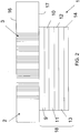
- the secure document 1 of the Fig. 2 is identical to that described in Fig. 1 with regard to the support 2 and the perforations 3.
- the secure document 1 comprises, on the lower face 17 of the support 2 opposite to the upper face 16 comprising data listed, a set of layers referenced in general 18.
- the assembly 18 comprises an adhesive layer 9 adapted to adhere to the support 2 permanently.
- This adhesive layer 9 is transparent to the light signals coming from the light source 5 mentioned above with reference to the Fig. 1 .
- the adhesive constituting the adhesive layer 9 is an adhesive that reacts to pressure or, preferably, to heat.
- the assembly 18 also comprises a reflecting layer 10.
- This reflecting layer 10 makes it possible to reflect the light signal 7 coming from the light source 5 towards the observer 6 as mentioned with reference to FIG. Fig. 1 .
- the assembly 18 also comprises a layer 11 capable of producing diffraction effects.
- the layer 11 is for example a thermoformable layer or a stamping layer. It comprises diffracting gratings producing visible diffraction effects at the order 0 or the order 1, or any other optical microstructure producing such effects. It is thermoformed in a manner known per se.
- the microstructures of the layer 11 extend at the interface between the layer 11 and the reflective layer 10, so that the reflective layer 10 is itself microstructured on the surface. Therefore, the reflective layer 10 is preferably transparent over its thickness. In this way, it is possible to observe the effects caused by the microstructures at the interface between the layers 10 and 11 through the perforations 3 when an observer 6 observes the support 2 by its upper face 16. It is therefore possible to see the perforations 3 in combination with the optical effects generated by the microstructures of the layer 11.
- the reflective layer 10 is for example a layer of a dielectric material of ZnS type deposited by vacuum evaporation or any other known method. The nature and the thickness of this reflective layer 10 are adapted to the optical effect generated by the thermoformable layer 11.
- the assembly 18 may also comprise a protective layer 12 intended to protect the layer 11 generating the optical effects.
- the protective layer 12 is for example a layer of varnish having a resistance to scratches and chemicals.
- the assembly 18 may also comprise a detachment layer 13, for example made of wax.
- the detachment layer 13 is such that it can detach from the protective layer 12 once the assembly 18 fixed to the support 2. By pulling on the polyester layer 14, the detachment layer 13 can detach from the layer 12 .
- the layers 12 and 13 are eliminated.
- the layers are fixed on the support 2 without detachment of the upper layers, and the polyester layer 14 then has a protective function of the layer 11 generating the optical effects, as the layer 12 described above.
- the assembly 18 comprises only an adhesive layer 9, a reflective layer 10, comprising for example in this case simply a mirror, and a protective layer 12 for protecting the mirror.
- the mirror forming the reflecting layer 10 can optionally be made transparent by applying a dielectric material, for example a ZnS zinc sulphide layer.
- the reflective layer 10 can also be replaced by a reflective metal layer.
- This metal layer may be continuous or partial so as to draw a pattern.
- the realization of such a type of reflector uses known demetallization techniques.
- the assembly 18 is made from processes known in the field of the production of transparent films. It can be delivered in reel or board. They can also be numbered to ensure easy counting for reasons of security, traceability or simply inventory management.
- the entire assembly 18 comprising at least one reflective layer 10, for example by hot rolling or pressing, is transferred.
- the assembly 18 comprises a detachment layer 13
- the layers of the above this detachment layer 13 On the FIG.2 the layers 13 and 14 are then peeled after the transfer.
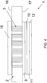
- the Fig. 4 illustrates another embodiment of the invention.
- the secure document 1 comprises a support 2 perforated perforations 3 with, on its lower face 17 opposite the upper face 16 on which data are written, an assembly 18 comprising at least one reflective layer 10.
- the assembly 18 illustrated on the Fig. 4 corresponds to the one shown in Fig. 3 or the one shown on the Fig. 2 when the layers 13 and 14 have been peeled.
- the secure document 1 also comprises a laminate 15 fixed on the upper face 16 of the support 2.
- the laminate 15 is a transparent film bonded to the support 2 so as to protect it from natural wear by physico / chemical resistance and also to prevent a deliberate degradation of the elements printed on the support 2 and protected by the film.
- the laminate 15 comprises optical elements such as holograms or diffraction gratings.
- the optical elements of the laminate 15 are advantageously combined with the optical elements of the thermoformed layer 11 of the assembly 18.
- the observer 6 when the observer 6 observes the upper face 16 of the support 2, he can see the light signal 7 emitted by the light source 5 which passes through the perforations 3, is reflected on the reflective layer 11 while generating the optical effects of layer 11 as mentioned above.
- the reflected signal 8 then crosses the perforations 3 again, and passes through the laminate 8 so as to generate new optical effects thanks to the optical elements of the laminate 8.
- the perforations 3 of the support 2 are advantageously used to combine optical effects generated by optical elements positioned on the upper faces 16 and lower 17 of the support 2, thanks to a reflection.
- the laminate 15 of the upper face 16 of the support 2 is transferred at the same time as the assembly 18 of the lower face 17 of the support 2 by hot transfer or pressing, after the perforation of the support 2, so as not to not introduce additional manufacturing steps.
- This embodiment also has the advantage of allowing the adhesive elements of the laminate 15 and the assembly 18 to merge through the perforations 3, which improves the strength of the support 2.
- the support 2 may be a page or a sheet of a personal document such as an identity card, a passport or a driving license, but also a fiduciary document such as a bank note or check.
Landscapes
- Physics & Mathematics (AREA)
- General Physics & Mathematics (AREA)
- Engineering & Computer Science (AREA)
- Theoretical Computer Science (AREA)
- Credit Cards Or The Like (AREA)
- Mirrors, Picture Frames, Photograph Stands, And Related Fastening Devices (AREA)
Description
L'invention se rapporte à un document sécurisé comprenant un support de données comprenant des perforations visibles par un observateur.The invention relates to a secure document comprising a data medium comprising perforations visible to an observer.
L'invention se rapporte également à un procédé pour sécuriser un document comprenant un support de données, le procédé comprenant au moins une étape dans laquelle :
- on perfore le support de données avec des perforations visibles par un observateur.
- the data carrier is perforated with perforations visible by an observer.
Un tel document sécurisé et un tel procédé sont connus de la publication
Dans ce document, le document sécurisé est un passeport. Une page de ce passeport comprend une photographie et une zone perforée. Les perforations de la page représentent sensiblement l'image de la photographie de sorte qu'il est possible d'identifier la page du passeport.In this document, the secure document is a passport. A page of this passport includes a photograph and a perforated area. The perforations of the page substantially represent the image of the photograph so that it is possible to identify the page of the passport.
Le document sécurisé décrit dans la publication susmentionnée possède toutefois des inconvénients. En effet, pour que les perforations soient visibles par l'utilisateur, il est nécessaire de faire passer de la lumière au travers des perforations. Pour ce faire, la publication précitée enseigne de soulever la page perforée vers la lumière pour voir les perforations par transmission et donc identifier le support. Dès lors, il est très simple, pour un contrefacteur, de réaliser de nouvelles perforations pour falsifier le support perforé. Ces nouvelles perforations seraient également détectées par transmission sans que l'on puisse distinguer si les nouvelles perforations ont été ajoutées de façon frauduleuse.The secure document described in the aforementioned publication, however, has disadvantages. Indeed, for the perforations to be visible to the user, it is necessary to pass light through the perforations. To do this, the above publication teaches to raise the perforated page to the light to see the perforations by transmission and thus identify the support. Therefore, it is very simple, for a counterfeiter, to make new perforations to falsify the perforated support. These new perforations would also be detected by transmission without it being possible to distinguish whether the new perforations were added fraudulently.
Au vu document précité, un problème résolu par l'invention est donc d'améliorer la sécurité conférée par les perforations du support.In view of the aforementioned document, a problem solved by the invention is therefore to improve the security conferred by the perforations of the support.
Ce problème est résolu par un document sécurisé suivant la revendication 1. Grâce à l'invention, si une éventuelle perforation de falsification est ajoutée aux perforations existantes dans le support par un fraudeur, ces perforations de falsifications vont traverser les moyens réfléchissants, de sorte que ces moyens ne réfléchiront plus la lumière au niveau de ces perforation de falsification. Il y aura donc une différence entre le signal réfléchi par les moyens réfléchissants qui correspond à l'image d'origine, et le signal transmis correspondant à l'image falsifiée. Il sera donc possible de détecter plus facilement une éventuelle falsification par ajout de perforations. Selon un mode de réalisation de l'invention, le support peut comprendre une première face et une deuxième face opposée à la première face, des données étant inscrite sur la première face, les moyens réfléchissants étant fixés sur la deuxième face de sorte que l'observateur puisse voir les perforations par réflexion sur les moyens réfléchissants lorsqu'il observe les données. Ce mode de réalisation a l'avantage de permettre de voir simultanément les données inscrites et les perforations par réflexion. Le fait que le mode de lecture des données inscrites et des perforations soit en réflexion facilite la vérification du document.This problem is solved by a secure document according to
De préférence, le document comprend en outre des moyens aptes à générer des effets optiques, les moyens aptes à générer des effets optiques étant agencés par rapport aux moyens réfléchissants de sorte que l'observateur puisse observer les effets optiques au travers des perforations par réflexion sur les moyens réfléchissants.Preferably, the document further comprises means capable of generating optical effects, the means capable of generating optical effects being arranged with respect to the reflecting means so that the observer can observe the optical effects through the perforations by reflection on reflective means.
Grâce à ce mode de réalisation, les perforations peuvent être vues par un observateur avec les effets optiques. Dans ce cas, les perforations permettent de personnaliser les effets optiques comme les hologrammes. Or, les moyens connus pour personnaliser les effets optiques sont complexes et consistent le plus souvent en un marquage laser ou en un hologramme en volume. Ce mode de réalisation permet au contraire de personnaliser simplement les effets optiques grâce aux perforations.With this embodiment, the perforations can be seen by an observer with the optical effects. In this case, the perforations make it possible to personalize optical effects such as holograms. However, the known means for customizing the optical effects are complex and usually consist of a laser marking or a volume hologram. This embodiment makes it possible, on the contrary, to simply personalize the optical effects thanks to the perforations.
De préférence, les moyens aptes à générer des effets optiques comprennent un réseau de diffraction produisant des effets de diffraction visibles à l'ordre 0 ou à l'ordre 1.Preferably, the means capable of generating optical effects comprise a diffraction grating producing visible diffraction effects at order 0 or
Selon un mode de réalisation de l'invention, le document sécurisé comprend un film adhésif fixé sur le support, le film adhésif comprenant les moyens réfléchissants.According to one embodiment of the invention, the secure document comprises an adhesive film fixed on the support, the adhesive film comprising the reflecting means.
Dans ce cas, le film adhésif peut comprendre une couche adhésive transparente adhérant au support, une couche transparente réfléchissante formant les moyens réfléchissants et une couche (apte à produire des effets optiques, la couche apte à produire des effets optiques étant agencée par rapport à la couche transparente réfléchissante de sorte que l'observateur puisse observer les effets optiques au travers des perforations par réflexion sur la couche transparente réfléchissante.In this case, the adhesive film may comprise a transparent adhesive layer adhering to the support, a reflective transparent layer forming the reflecting means and a layer (capable of producing optical effects, the layer capable of producing optical effects being arranged with respect to the reflective transparent layer so that the observer can observe the optical effects through the reflective perforations on the transparent reflective layer.
Un tel agencement par film adhésif permet notamment une application des moyens réfléchissant par transfert à chaud ou par pressage.Such an arrangement by adhesive film allows in particular an application of the reflective means by hot transfer or pressing.
De préférence, la couche transparente réfléchissante est superposée à la couche adhésive, et la couche apte à produire des effets optiques est superposée à la couche réfléchissante transparente.Preferably, the reflective transparent layer is superimposed on the adhesive layer, and the layer capable of producing optical effects is superimposed on the transparent reflective layer.
Dans ce cas, la couche apte à produire des effets optiques peut comprendre un réseau de diffraction produisant des effets de diffraction visibles à l'ordre 0 ou à l'ordre 1, le réseau de diffraction étant agencé par rapport à la couche transparente réfléchissante de sorte à structurer une surface de la couche transparente réfléchissante, pour que l'observateur puisse observer les effets de diffraction au travers des perforations par réflexion sur la couche transparente réfléchissante.In this case, the layer capable of producing optical effects may comprise a diffraction grating producing visible diffraction effects at the order 0 or at the
La couche transparente réfléchissante peut être formée en un matériau diélectrique transparent.The reflective transparent layer may be formed of a transparent dielectric material.
Selon un mode de réalisation de l'invention, le document sécurisé comprend un film fixé sur la première face du support, le film étant agencé pour générer des premiers effets optiques, le document comprenant en outre des moyens aptes à générer des deuxième effets optiques, les moyens aptes à générer des deuxième effets optiques étant fixés à la deuxième face du support et agencés par rapport aux moyens réfléchissants pour que l'observateur puisse observer les deuxième effets optiques au travers des perforations par réflexion sur les moyens réfléchissants, de sorte que l'observateur puisse voir les premiers effets optiques et les deuxièmes effets optiques lorsqu'il observe la première face du support.According to one embodiment of the invention, the secure document comprises a film fixed on the first face of the support, the film being arranged to generate first optical effects, the document further comprising means capable of generating second optical effects, the means capable of generating second optical effects being fixed to the second face of the support and arranged with respect to the reflecting means so that the observer can observe the second optical effects through the perforations by reflection on the reflecting means, so that the observer can see the first optical effects and the second optical effects when he observes the first face of the support.
De préférence, le document comprend un film adhésif adhérant à la deuxième face du support, le film adhésif comprenant une couche adhésive transparente adhérant au support, une couche transparente réfléchissante formant les moyens réfléchissants et une couche apte à produire les deuxième effets optiques, la couche apte à produire les deuxième effets optiques étant agencée par rapport à la couche transparente réfléchissante de sorte que l'observateur puisse observer les deuxième effets optiques au travers des perforations par réflexion sur la couche transparente réfléchissante.Preferably, the document comprises an adhesive film adhering to the second face of the support, the adhesive film comprising a transparent adhesive layer adhering to the support, a reflective transparent layer forming the reflecting means and a layer capable of producing the second optical effects, the layer adapted to produce the second optical effects being arranged with respect to the reflective transparent layer so that the observer can observe the second optical effects through the reflective perforations on the transparent reflective layer.
Dans tous les modes de réalisation mentionnés ci-dessus, le support peut être en papier, en plastique, ou en polycarbonate.In all the embodiments mentioned above, the support may be paper, plastic, or polycarbonate.
L'invention se rapporte également à un procédé pour sécuriser un document suivant la revendication 11. De préférence, l'étape d'ajout est réalisée après l'étape de perforation. De la sorte, on garantit que les moyens réfléchissants ne sont pas perforés et peuvent donc correctement réfléchir la lumière. De préférence, le support comprend une première face et une deuxième face opposée à la première face, des données étant inscrite sur la première face, et dans lequel dans l'étape d'ajout, on fixe les moyens réfléchissants à la deuxième face du support.The invention also relates to a method for securing a document according to
Selon un mode de réalisation, le procédé comprend en outre une étape dans laquelle on fixe un film transparent sur la première face du support après l'étape de perforation. Comme précédemment, le fait de fixer le film transparent après la perforation permet garantir que le film transparent de la première face ne sera pas perforé.According to one embodiment, the method further comprises a step in which a transparent film is fixed on the first face of the support after the perforation step. As before, fixing the transparent film after perforation ensures that the transparent film of the first face will not be perforated.
En outre, l'ajout du film transparent et l'ajout des moyens réfléchissants peuvent être réalisés lors d'un même transfert.In addition, the addition of the transparent film and the addition of reflective means can be performed during the same transfer.
On décrit maintenant un mode de réalisation de l'invention en référence aux figures annexées dans lesquelles :
-
FIG. 1 représente un support d'un document sécurisé selon l'invention ; -
FIG. 2 représente un document sécurisé selon un mode de réalisation de l'invention ; -
FIG. 3 représente un document sécurisé selon un autre mode de réalisation de l'invention ; -
FIG. 4 représente un document sécurisé selon encore un autre mode de réalisation de l'invention.
-
Fig. 1 represents a support of a secure document according to the invention; -
Fig. 2 represents a secure document according to one embodiment of the invention; -
Fig. 3 represents a secure document according to another embodiment of the invention; -
Fig. 4 represents a secure document according to yet another embodiment of the invention.
Sur les figures mentionnées ci-dessus, des références identiques se rapportent, sauf indication contraire, à des caractéristiques techniques similaires.In the figures mentioned above, identical references refer, unless otherwise indicated, to similar technical characteristics.
Comme illustré
La fréquence, le diamètre, la forme et l'orientation des perforations 3 dans le support peuvent être facilement adaptés en fonction de la nature du support 2 du document sécurisé 1. De telles perforations, parfois appelées micro-perforations sont connues dans le domaine de la sécurisation des documents. Une taille typique pour les perforations est d'environ 200 micromètres.The frequency, the diameter, the shape and the orientation of the
Dans un exemple particulier de l'invention, le document sécurisé 1 est un document personnel associé à un porteur du type passeport, carte d'identité ou permis de conduire, et le support 2 correspond à une page ou une feuille de ce document sécurisé 1. Le support 2 peut être en différents matériaux selon la nature du document constituant le document sécurisé 1, et notamment en papier, en plastique, ou en polycarbonate.In a particular example of the invention, the
Lorsque le document sécurisé 1 est un document personnel du type passeport, carte d'identité ou permis de conduire, les perforations 3 représentent, de façon connue en soi, au moins une donnée personnelle du porteur, et notamment la date de naissance du porteur, le nom du porteur, ou la photographie du porteur.When the
Des données relatives au porteur sont également inscrites sur la face supérieure 16 du support 2. Ainsi, un observateur 6 observe le support 2 par la face supérieure 16.Data relating to the carrier is also written on the
Le document sécurisé 1 comprend également une couche réfléchissante 4 collée à la face inférieure 17 du support 2.The
Grâce à cette couche réfléchissante 4, lorsqu'un observateur 6 observe les données inscrites sur la face supérieure 16 du support 2, il peut également observer la forme représentée par les perforations 3. En effet, une source lumineuse 5, par exemple la lumière du jour ou tout autre type de lumière, émet un signal lumineux 7, qui traverse les perforations 3 et se réfléchi sur la couche réfléchissante 4. Le signal réfléchi 8 traverse alors les perforations 3 et peut être observé par l'observateur 6.Thanks to this
Selon les caractéristiques du document sécurisé 1 et des perforations 3, la source lumineuse 5 peut être une source dans le visible, de sorte que les perforations 3 soient visibles en réflexion à l'oeil nu, ou bien une source dans l'infrarouge ou l'ultraviolet.According to the characteristics of the
La couche réfléchissante 4 est par exemple collée sur la face inférieure 17 du support 12 grâce à une colle transparente aux signaux lumineux émis par la source lumineuse 5 afin de ne pas gêner la réflexion des signaux lumineux émis par la source lumineuse 5 vers l'observateur 6.The
On décrit maintenant un mode de réalisation particulier de l'invention en référence à la
Le document sécurisé 1 de la
A la place de la simple couche réfléchissante 4 illustrée à la
L'ensemble 18 comprend une couche adhésive 9 adaptée pour adhérer au support 2 de façon permanente. Cette couche adhésive 9 est transparente aux signaux lumineux issus de la source lumineuse 5 mentionnée ci-dessus en référence à la
L'ensemble 18 comprend également une couche réfléchissante 10. Cette couche réfléchissante 10 permet de réfléchir le signal lumineux 7 issu de la source lumineuse 5 vers l'observateur 6 comme mentionné en référence à la
L'ensemble 18 comprend également une couche 11 apte à produire des effets de diffraction. La couche 11 est par exemple une couche thermoformable ou une couche d'estampage. Elle comprend des réseaux diffractants produisant des effets de diffraction visibles à l'ordre 0 ou à l'ordre 1, ou tout autre microstructure optique produisant de tels effets. Elle est thermoformée de façon connue en soi.The
De façon également connue, les microstructures de la couche 11 s'étendent à l'interface entre la couche 11 et la couche réfléchissante 10, de sorte que la couche réfléchissante 10 est elle-même microstructurée en surface. Dès lors, la couche réfléchissante 10 est de préférence transparente sur son épaisseur. De la sorte, il est possible d'observer les effets provoqués par les microstructures à l'interface entre les couches 10 et 11 à travers les perforations 3 lorsqu'un observateur 6 observe le support 2 par sa face supérieure 16. Il est donc possible de voir les perforations 3 en combinaison avec les effets optiques générés par les microstructures de la couche 11.Also known, the microstructures of the
La couche réfléchissante 10 est par exemple une couche d'un matériau diélectrique du type ZnS déposée par évaporation sous vide ou tout autre procédé connu. La nature et l'épaisseur de cette couche réfléchissante 10 sont adaptées à l'effet optique généré par la couche thermoformable 11.The
L'ensemble 18 peut également comprendre une couche protectrice 12 destinée à protéger la couche 11 générant les effets optiques. La couche protectrice 12 est par exemple une couche de vernis présentant une résistance aux rayures et aux produits chimiques.The
L'ensemble 18 peut également comprendre une couche 13 de détachement par exemple formée de cire.The
Il comprend également une couche en polyester 14 ayant une épaisseur comprise entre 10 et 50 micromètres.It also comprises a
La couche de détachement 13 est telle qu'elle peut se détacher de la couche protectrice 12 une fois l'ensemble 18 fixé au support 2. En tirant sur la couche en polyester 14, la couche de détachement 13 peut se détacher de la couche 12.The
Ainsi, après détachement de la couche de détachement 13, seules les couches 9, 10, 11 et 12 restent fixées sur le support 2.Thus, after detachment of the
Selon une variante de ce mode de réalisation, on supprime les couches 12 et 13. Dans ce cas, les couches sont fixées sur le support 2 sans détachement de couches supérieures, et la couche de polyester 14 a alors une fonction de protection de la couche 11 générant les effets optiques, comme la couche 12 précédemment décrite.According to a variant of this embodiment, the
Selon une autre variante de ce mode de réalisation, on peut également supprimer la couche 11 générant les effets optiques. Dans ce cas, comme illustré
De même, la couche réfléchissante 10 peut également être remplacée par une couche de métal réfléchissant. Cette couche de métal peut être continue ou partielle de manière à dessiner un motif. La réalisation d'un tel type de réflecteur utilise les techniques de demétallisation connues.Similarly, the
L'ensemble 18 est réalisé à partir de procédés connus dans le domaine de la réalisation de films transparents. Il peut être livré en bobine ou en planche. Ils peuvent également être numéroté de façon à assurer un décompte facile pour des raisons de sécurité, de traçabilité ou tout simplement de gestion de stock.The
Une fois les perforations 3 du support 2 réalisées, par exemple par gravure laser, on procède au transfert de l'ensemble 18 comprenant au moins une couche réfléchissante 10, par exemple par laminage à chaud ou pressage. Lorsque l'ensemble 18 comprend une couche de détachement 13, on procède au pelage des couches situées au dessus de cette couche de détachement 13. Sur la
La
Comme illustré sur la
Dans le mode de réalisation illustré sur la
Le laminat 15 est un film transparent collé sur le support 2 de manière à le protéger de l'usure naturelle par résistance physico/chimique et également d'empêcher une dégradation volontaire des éléments imprimés sur le support 2 et protégés par le film.The laminate 15 is a transparent film bonded to the
De façon connue en soi, un laminat peut comporter plusieurs couches techniques dont au minimum une des couches suivantes:
- une couche estampée comportant des éléments visuels de différents niveaux de sécurité tels que des hologrammes ou des réseaux de diffraction
- une couche réflective de nature métallique ou diélectrique, pouvant même être appliquée de manière non uniforme
- des impressions visibles variables ou fixes, invisibles (UV, IR, ou autre), réactivables.
- a stamped layer comprising visual elements of different security levels such as holograms or diffraction gratings
- a reflective layer of a metallic or dielectric nature, which can even be applied in a non-uniform manner
- variable or fixed, invisible (UV, IR, or other) visible impressions, which can be reactivated.
Selon ce mode de réalisation de l'invention, le laminat 15 comprend des éléments optiques tels que des hologrammes ou des réseaux de diffraction.According to this embodiment of the invention, the laminate 15 comprises optical elements such as holograms or diffraction gratings.
Dans ce cas, les éléments optiques du laminat 15 se combinent avantageusement avec les éléments optiques de la couche thermoformée 11 de l'ensemble 18.In this case, the optical elements of the laminate 15 are advantageously combined with the optical elements of the
En effet, lorsque l'observateur 6 observe la face supérieure 16 du support 2, il peut voir le signal lumineux 7 émis par la source lumineuse 5 qui traverse les perforations 3, se réfléchit sur la couche réfléchissante 11 tout en générant les effets optiques de la couche 11 comme mentionné ci-dessus. Le signal réfléchi 8 traverse alors de nouveau les perforations 3, et traverse le laminat 8 de sorte à générer de nouveaux effets optiques grâce aux éléments optiques du laminat 8.Indeed, when the
Ainsi, selon ce mode de réalisation, les perforations 3 du support 2 sont avantageusement utilisées pour combiner des effets optiques générés par des éléments optiques positionnés sur les faces supérieures 16 et inférieures 17 du support 2, grâce à une réflexion.Thus, according to this embodiment, the
De préférence, le laminat 15 de la face supérieure 16 du support 2 est transféré en même temps que l'ensemble 18 de la face inférieure 17 du support 2 par transfert à chaud ou pressage, après la perforation du support 2, de sorte à ne pas introduire d'étapes supplémentaires de fabrication. Ce mode de réalisation a en outre l'avantage de permettre une fusion des éléments adhésifs du laminat 15 et de l'ensemble 18 au travers des perforations 3, ce qui améliore la résistance du support 2.Preferably, the
Dans tous les modes de réalisation décrits ci-dessus, le support 2 peut être une page ou une feuille d'un document personnel comme une carte d'identité, un passeport ou un permis de conduire, mais également d'un document fiduciaire comme un billet de banque ou un chèque.In all the embodiments described above, the
Claims (15)
- Secure document (1) comprising a data carrier (2), said carrier (2) comprising:- a first face (16) and a second face (17) that is opposite said first face (16), and- perforations (3) that are visible to an observer (6),
characterized in that:- the secure document (1) is a personal document associated with an owner, comprising data relating to the owner inscribed on the first face (16);- the perforations (3) represent a least one personal datum of the owner; and- the secure document (1) comprises reflecting means (10, 4) that are adhesively bonded to the second face (17) of the carrier (2) and that are arranged so that light that passes through the perforations (3) in the carrier (2) is reflected through the perforations so that an observer can simultaneously see the inscribed data and said perforations in reflection. - Secure document (1) according to Claim 1, furthermore comprising means (11) that are suitable for generating optical effects, the means (11) that are suitable for generating optical effects being arranged, with respect to the reflecting means (10, 4), so that the observer is able to observe the optical effects through the perforations in reflection from the reflecting means (10, 4).
- Secure document (1) according to the preceding claim, wherein the means (11) that are able to generate optical effects comprise a diffraction grating that produces zeroth-order or first-order visible diffraction effects.
- Secure document (1) according to one of the preceding claims, comprising an adhesive film (18) that is fastened to the carrier (2), the adhesive film comprising the reflecting means (10).
- Secure document (1) according to the preceding claim, wherein the adhesive film (18) comprises a transparent adhesive layer (9) that adheres to the carrier (2), a reflective transparent layer (10) forming the reflecting means (10) and a layer (11) that is able to produce optical effects, the layer (11) that is able to produce optical effects being arranged, with respect to the reflective transparent layer, so that the observer may observe the optical effects through the perforations in reflection from the reflective transparent layer.
- Secure document (1) according to the preceding claim, wherein the reflective transparent layer (10) is superposed on the adhesive layer (9), and the layer (11) that is able to produce optical effects is superposed on the transparent reflective layer (10).
- Secure document (1) according to either of Claims 5 and 6, wherein the layer (11) that is able to produce optical effects comprises a diffraction grating that produces zeroth-order or first-order visible diffraction effects, the diffraction grating being arranged, with respect to the reflective transparent layer, so as to structure a surface of the reflective transparent layer, so that the observer may observe the diffraction effects through the perforations in reflection from the reflective transparent layer.
- Secure document (1) according to the preceding claim, wherein the reflective transparent layer (10) is made of a transparent dielectric material.
- Secure document (1) according to any one of the preceding claims, wherein the secure document (1) comprises a film (15) that is fastened to the first face (16) of the carrier, the film (15) being arranged to generate first optical effects, the secure document (1) furthermore comprising means (11) that are able to generate second optical effects, the means (11) that are able to generate second optical effects being fastened to the second face of the carrier (2) and arranged, with respect to the reflecting means (10, 4), so that the observer may observe the second optical effects through the perforations in reflection from the reflecting means (10, 4), so that the observer may see the first optical effects and the second optical effects when he observes the first face (16) of the carrier (2).
- Secure document (1) according to the preceding claim, comprising an adhesive film (18) that adheres to the second face (17) of the carrier (2), the adhesive film (18) comprising a transparent adhesive layer (9) that adheres to the carrier (2), a reflective transparent layer (10) forming the reflecting means (10) and a layer (11) that is able to produce the second optical effects, the layer (11) that is able to produce the second optical effects being arranged, with respect to the reflective transparent layer, so that the observer may observe the second optical effects through the perforations in reflection from the reflective transparent layer.
- Method for making secure a personal document that is associated with an owner and that comprises a data carrier and data relating to the owner, said data being inscribed on a first face, the method comprising steps of:- perforating, in which step the data carrier is perforated with perforations that represent at least one personal datum of the owner and that are visible to an observer; and- adding, in which step reflecting means are added to the carrier, said means being adhesively bonded to a second face of the carrier, which face is opposite the first face, and arranged so that light passing through the perforations in the carrier is reflected through the perforations so that an observer may simultaneously see the inscribed data and the perforations in reflection.
- Method according to Claim 11, wherein the adding step is carried out after the perforating step.
- Method according to either of Claims 11 and 12, wherein the carrier (2) comprises a first face (16) and a second face (17) that is opposite the first face (16), data being inscribed on the first face (16), and wherein, in the adding step, the reflecting means are fastened to the second face (17) of the carrier.
- Method according to the preceding claim, furthermore comprising a step in which a transparent film (15) is fastened to the first face (16) of the carrier (2) after the perforating step.
- Method according to the preceding claim, wherein the addition of the transparent film (15) and the addition of the reflecting means is carried out in the same transferring operation.
Applications Claiming Priority (2)
| Application Number | Priority Date | Filing Date | Title |
|---|---|---|---|
| FR0706216A FR2920340A1 (en) | 2007-09-05 | 2007-09-05 | Secured document e.g. passport, has data support with perforations which are visible by observer, and reflecting unit arranged such that light traversing perforations are reflected through perforations |
| PCT/FR2008/001238 WO2009066017A2 (en) | 2007-09-05 | 2008-09-05 | Secure document and method for making a document secure |
Publications (2)
| Publication Number | Publication Date |
|---|---|
| EP2185367A2 EP2185367A2 (en) | 2010-05-19 |
| EP2185367B1 true EP2185367B1 (en) | 2018-08-08 |
Family
ID=39301063
Family Applications (1)
| Application Number | Title | Priority Date | Filing Date |
|---|---|---|---|
| EP08851219.9A Not-in-force EP2185367B1 (en) | 2007-09-05 | 2008-09-05 | Secure document and method for making a document secure |
Country Status (3)
| Country | Link |
|---|---|
| EP (1) | EP2185367B1 (en) |
| FR (1) | FR2920340A1 (en) |
| WO (1) | WO2009066017A2 (en) |
Families Citing this family (2)
| Publication number | Priority date | Publication date | Assignee | Title |
|---|---|---|---|---|
| PL2512742T3 (en) * | 2009-12-18 | 2014-08-29 | Orell Fuessli Sicherheitsdruck Ag | Security document with optical waveguide |
| DE102015009164A1 (en) * | 2015-07-14 | 2017-01-19 | Giesecke & Devrient Gmbh | Disk with breakthrough area |
Citations (1)
| Publication number | Priority date | Publication date | Assignee | Title |
|---|---|---|---|---|
| WO1998019869A1 (en) * | 1996-11-05 | 1998-05-14 | Industrial Automation Integrators (Iai) B.V. | Security feature comprising a perforation pattern |
Family Cites Families (11)
| Publication number | Priority date | Publication date | Assignee | Title |
|---|---|---|---|---|
| GB8911271D0 (en) * | 1989-05-17 | 1989-07-05 | Hewitt Brian | Holographic devices and uses thereof |
| DE3932505C2 (en) * | 1989-09-28 | 2001-03-15 | Gao Ges Automation Org | Data carrier with an optically variable element |
| GB9025390D0 (en) * | 1990-11-22 | 1991-01-09 | De La Rue Thomas & Co Ltd | Security device |
| GB9106128D0 (en) * | 1991-03-22 | 1991-05-08 | Amblehurst Ltd | Article |
| DE4334847A1 (en) * | 1993-10-13 | 1995-04-20 | Kurz Leonhard Fa | Value document with window |
| US6045894A (en) * | 1998-01-13 | 2000-04-04 | 3M Innovative Properties Company | Clear to colored security film |
| GB0016356D0 (en) * | 2000-07-03 | 2000-08-23 | Optaglio Ltd | Optical structure |
| DE102004014778A1 (en) * | 2004-03-26 | 2005-10-13 | Leonard Kurz Gmbh & Co. Kg | Security and / or value document |
| GB0409747D0 (en) * | 2004-04-30 | 2004-06-09 | Rue De Int Ltd | Improvements in substrates incorporating security devices |
| DE102004044458B4 (en) * | 2004-09-15 | 2010-01-07 | Ovd Kinegram Ag | The security document |
| EP1827866B1 (en) * | 2004-11-23 | 2009-05-27 | Orell Füssli Sicherheitsdruck AG | Security document comprising a light source and a light-processing device |
-
2007
- 2007-09-05 FR FR0706216A patent/FR2920340A1/en not_active Withdrawn
-
2008
- 2008-09-05 EP EP08851219.9A patent/EP2185367B1/en not_active Not-in-force
- 2008-09-05 WO PCT/FR2008/001238 patent/WO2009066017A2/en not_active Ceased
Patent Citations (1)
| Publication number | Priority date | Publication date | Assignee | Title |
|---|---|---|---|---|
| WO1998019869A1 (en) * | 1996-11-05 | 1998-05-14 | Industrial Automation Integrators (Iai) B.V. | Security feature comprising a perforation pattern |
Also Published As
| Publication number | Publication date |
|---|---|
| FR2920340A1 (en) | 2009-03-06 |
| WO2009066017A2 (en) | 2009-05-28 |
| EP2185367A2 (en) | 2010-05-19 |
| WO2009066017A3 (en) | 2009-09-03 |
Similar Documents
| Publication | Publication Date | Title |
|---|---|---|
| EP3154795B1 (en) | Method for manufacturing a multilayer data medium with security marking which can be marked by laser | |
| WO2008119904A2 (en) | Security document including an rfid device | |
| FR3007318A1 (en) | MULTILAYER SAFETY STRUCTURE AND METHOD OF MANUFACTURING THE SAME | |
| EP3148818B1 (en) | Use of an optical security component for customising a security document and production of such a component | |
| EP3071420B1 (en) | Customizable document for producing a security document, customized security document and production of such a security document | |
| EP2382097B1 (en) | Customised security document and procedure for securing a document | |
| EP2648912B1 (en) | Secure product and method of producing said secure product | |
| EP2407314B1 (en) | Method for producing a pattern on a substrate using security ink | |
| EP2185367B1 (en) | Secure document and method for making a document secure | |
| WO2011051881A1 (en) | Method for producing a support comprising an electronic device | |
| EP3640040B1 (en) | Safety film and method for manufacturing a safety film | |
| EP2156375B1 (en) | Flexible adhesive label for security furnished with at least one contactless microcircuit for an official document | |
| EP1952311B1 (en) | Data medium, identity document and corresponding security-protection method | |
| FR2867590A1 (en) | Object e.g. travel document, protection method, involves applying decoding films with decoding patterns on object such that shallow image can be readable by indirect visualization across decoding pattern superposed with source pattern | |
| WO2015049610A1 (en) | Multilayer security structure and associated method of manufacture | |
| WO2024094521A1 (en) | Security optical device | |
| WO2010043816A1 (en) | Flexible security decal including at least one microcircuit | |
| FR3105757A1 (en) | Security document with a pattern of laser perforations | |
| FR2853970A1 (en) | A translucent support bearing a motif visible in reflected light, but not in transmitted light consisting of a transparent holographic film with a wide angle amplitude hologram sandwiched between two layers of natural tracing paper |
Legal Events
| Date | Code | Title | Description |
|---|---|---|---|
| PUAI | Public reference made under article 153(3) epc to a published international application that has entered the european phase |
Free format text: ORIGINAL CODE: 0009012 |
|
| 17P | Request for examination filed |
Effective date: 20100302 |
|
| AK | Designated contracting states |
Kind code of ref document: A2 Designated state(s): AT BE BG CH CY CZ DE DK EE ES FI FR GB GR HR HU IE IS IT LI LT LU LV MC MT NL NO PL PT RO SE SI SK TR |
|
| AX | Request for extension of the european patent |
Extension state: AL BA MK RS |
|
| DAX | Request for extension of the european patent (deleted) | ||
| RAP1 | Party data changed (applicant data changed or rights of an application transferred) |
Owner name: SURYS |
|
| 17Q | First examination report despatched |
Effective date: 20161202 |
|
| REG | Reference to a national code |
Ref country code: DE Ref legal event code: R079 Ref document number: 602008056425 Country of ref document: DE Free format text: PREVIOUS MAIN CLASS: B42D0015100000 Ipc: B42D0015000000 |
|
| GRAP | Despatch of communication of intention to grant a patent |
Free format text: ORIGINAL CODE: EPIDOSNIGR1 |
|
| RIC1 | Information provided on ipc code assigned before grant |
Ipc: B42D 15/00 20060101AFI20180228BHEP |
|
| INTG | Intention to grant announced |
Effective date: 20180315 |
|
| GRAS | Grant fee paid |
Free format text: ORIGINAL CODE: EPIDOSNIGR3 |
|
| GRAA | (expected) grant |
Free format text: ORIGINAL CODE: 0009210 |
|
| AK | Designated contracting states |
Kind code of ref document: B1 Designated state(s): AT BE BG CH CY CZ DE DK EE ES FI FR GB GR HR HU IE IS IT LI LT LU LV MC MT NL NO PL PT RO SE SI SK TR |
|
| REG | Reference to a national code |
Ref country code: GB Ref legal event code: FG4D Free format text: NOT ENGLISH |
|
| REG | Reference to a national code |
Ref country code: CH Ref legal event code: EP Ref country code: AT Ref legal event code: REF Ref document number: 1026544 Country of ref document: AT Kind code of ref document: T Effective date: 20180815 |
|
| REG | Reference to a national code |
Ref country code: IE Ref legal event code: FG4D Free format text: LANGUAGE OF EP DOCUMENT: FRENCH |
|
| REG | Reference to a national code |
Ref country code: DE Ref legal event code: R096 Ref document number: 602008056425 Country of ref document: DE |
|
| REG | Reference to a national code |
Ref country code: FR Ref legal event code: PLFP Year of fee payment: 11 |
|
| REG | Reference to a national code |
Ref country code: NL Ref legal event code: MP Effective date: 20180808 |
|
| REG | Reference to a national code |
Ref country code: LT Ref legal event code: MG4D |
|
| REG | Reference to a national code |
Ref country code: AT Ref legal event code: MK05 Ref document number: 1026544 Country of ref document: AT Kind code of ref document: T Effective date: 20180808 |
|
| PG25 | Lapsed in a contracting state [announced via postgrant information from national office to epo] |
Ref country code: NO Free format text: LAPSE BECAUSE OF FAILURE TO SUBMIT A TRANSLATION OF THE DESCRIPTION OR TO PAY THE FEE WITHIN THE PRESCRIBED TIME-LIMIT Effective date: 20181108 Ref country code: AT Free format text: LAPSE BECAUSE OF FAILURE TO SUBMIT A TRANSLATION OF THE DESCRIPTION OR TO PAY THE FEE WITHIN THE PRESCRIBED TIME-LIMIT Effective date: 20180808 Ref country code: IS Free format text: LAPSE BECAUSE OF FAILURE TO SUBMIT A TRANSLATION OF THE DESCRIPTION OR TO PAY THE FEE WITHIN THE PRESCRIBED TIME-LIMIT Effective date: 20181208 Ref country code: SE Free format text: LAPSE BECAUSE OF FAILURE TO SUBMIT A TRANSLATION OF THE DESCRIPTION OR TO PAY THE FEE WITHIN THE PRESCRIBED TIME-LIMIT Effective date: 20180808 Ref country code: GR Free format text: LAPSE BECAUSE OF FAILURE TO SUBMIT A TRANSLATION OF THE DESCRIPTION OR TO PAY THE FEE WITHIN THE PRESCRIBED TIME-LIMIT Effective date: 20181109 Ref country code: FI Free format text: LAPSE BECAUSE OF FAILURE TO SUBMIT A TRANSLATION OF THE DESCRIPTION OR TO PAY THE FEE WITHIN THE PRESCRIBED TIME-LIMIT Effective date: 20180808 Ref country code: PL Free format text: LAPSE BECAUSE OF FAILURE TO SUBMIT A TRANSLATION OF THE DESCRIPTION OR TO PAY THE FEE WITHIN THE PRESCRIBED TIME-LIMIT Effective date: 20180808 Ref country code: NL Free format text: LAPSE BECAUSE OF FAILURE TO SUBMIT A TRANSLATION OF THE DESCRIPTION OR TO PAY THE FEE WITHIN THE PRESCRIBED TIME-LIMIT Effective date: 20180808 Ref country code: BG Free format text: LAPSE BECAUSE OF FAILURE TO SUBMIT A TRANSLATION OF THE DESCRIPTION OR TO PAY THE FEE WITHIN THE PRESCRIBED TIME-LIMIT Effective date: 20181108 Ref country code: LT Free format text: LAPSE BECAUSE OF FAILURE TO SUBMIT A TRANSLATION OF THE DESCRIPTION OR TO PAY THE FEE WITHIN THE PRESCRIBED TIME-LIMIT Effective date: 20180808 |
|
| PG25 | Lapsed in a contracting state [announced via postgrant information from national office to epo] |
Ref country code: ES Free format text: LAPSE BECAUSE OF FAILURE TO SUBMIT A TRANSLATION OF THE DESCRIPTION OR TO PAY THE FEE WITHIN THE PRESCRIBED TIME-LIMIT Effective date: 20180808 Ref country code: HR Free format text: LAPSE BECAUSE OF FAILURE TO SUBMIT A TRANSLATION OF THE DESCRIPTION OR TO PAY THE FEE WITHIN THE PRESCRIBED TIME-LIMIT Effective date: 20180808 Ref country code: LV Free format text: LAPSE BECAUSE OF FAILURE TO SUBMIT A TRANSLATION OF THE DESCRIPTION OR TO PAY THE FEE WITHIN THE PRESCRIBED TIME-LIMIT Effective date: 20180808 |
|
| PG25 | Lapsed in a contracting state [announced via postgrant information from national office to epo] |
Ref country code: EE Free format text: LAPSE BECAUSE OF FAILURE TO SUBMIT A TRANSLATION OF THE DESCRIPTION OR TO PAY THE FEE WITHIN THE PRESCRIBED TIME-LIMIT Effective date: 20180808 Ref country code: RO Free format text: LAPSE BECAUSE OF FAILURE TO SUBMIT A TRANSLATION OF THE DESCRIPTION OR TO PAY THE FEE WITHIN THE PRESCRIBED TIME-LIMIT Effective date: 20180808 Ref country code: CZ Free format text: LAPSE BECAUSE OF FAILURE TO SUBMIT A TRANSLATION OF THE DESCRIPTION OR TO PAY THE FEE WITHIN THE PRESCRIBED TIME-LIMIT Effective date: 20180808 Ref country code: IT Free format text: LAPSE BECAUSE OF FAILURE TO SUBMIT A TRANSLATION OF THE DESCRIPTION OR TO PAY THE FEE WITHIN THE PRESCRIBED TIME-LIMIT Effective date: 20180808 |
|
| REG | Reference to a national code |
Ref country code: CH Ref legal event code: PL |
|
| REG | Reference to a national code |
Ref country code: DE Ref legal event code: R097 Ref document number: 602008056425 Country of ref document: DE |
|
| PG25 | Lapsed in a contracting state [announced via postgrant information from national office to epo] |
Ref country code: SK Free format text: LAPSE BECAUSE OF FAILURE TO SUBMIT A TRANSLATION OF THE DESCRIPTION OR TO PAY THE FEE WITHIN THE PRESCRIBED TIME-LIMIT Effective date: 20180808 Ref country code: DK Free format text: LAPSE BECAUSE OF FAILURE TO SUBMIT A TRANSLATION OF THE DESCRIPTION OR TO PAY THE FEE WITHIN THE PRESCRIBED TIME-LIMIT Effective date: 20180808 |
|
| REG | Reference to a national code |
Ref country code: BE Ref legal event code: MM Effective date: 20180930 |
|
| PLBE | No opposition filed within time limit |
Free format text: ORIGINAL CODE: 0009261 |
|
| STAA | Information on the status of an ep patent application or granted ep patent |
Free format text: STATUS: NO OPPOSITION FILED WITHIN TIME LIMIT |
|
| REG | Reference to a national code |
Ref country code: IE Ref legal event code: MM4A |
|
| PG25 | Lapsed in a contracting state [announced via postgrant information from national office to epo] |
Ref country code: MC Free format text: LAPSE BECAUSE OF FAILURE TO SUBMIT A TRANSLATION OF THE DESCRIPTION OR TO PAY THE FEE WITHIN THE PRESCRIBED TIME-LIMIT Effective date: 20180808 Ref country code: LU Free format text: LAPSE BECAUSE OF NON-PAYMENT OF DUE FEES Effective date: 20180905 |
|
| 26N | No opposition filed |
Effective date: 20190509 |
|
| PG25 | Lapsed in a contracting state [announced via postgrant information from national office to epo] |
Ref country code: IE Free format text: LAPSE BECAUSE OF NON-PAYMENT OF DUE FEES Effective date: 20180905 |
|
| PG25 | Lapsed in a contracting state [announced via postgrant information from national office to epo] |
Ref country code: CH Free format text: LAPSE BECAUSE OF NON-PAYMENT OF DUE FEES Effective date: 20180930 Ref country code: SI Free format text: LAPSE BECAUSE OF FAILURE TO SUBMIT A TRANSLATION OF THE DESCRIPTION OR TO PAY THE FEE WITHIN THE PRESCRIBED TIME-LIMIT Effective date: 20180808 Ref country code: LI Free format text: LAPSE BECAUSE OF NON-PAYMENT OF DUE FEES Effective date: 20180930 Ref country code: BE Free format text: LAPSE BECAUSE OF NON-PAYMENT OF DUE FEES Effective date: 20180930 |
|
| PG25 | Lapsed in a contracting state [announced via postgrant information from national office to epo] |
Ref country code: MT Free format text: LAPSE BECAUSE OF FAILURE TO SUBMIT A TRANSLATION OF THE DESCRIPTION OR TO PAY THE FEE WITHIN THE PRESCRIBED TIME-LIMIT Effective date: 20180808 |
|
| PG25 | Lapsed in a contracting state [announced via postgrant information from national office to epo] |
Ref country code: TR Free format text: LAPSE BECAUSE OF FAILURE TO SUBMIT A TRANSLATION OF THE DESCRIPTION OR TO PAY THE FEE WITHIN THE PRESCRIBED TIME-LIMIT Effective date: 20180808 |
|
| PG25 | Lapsed in a contracting state [announced via postgrant information from national office to epo] |
Ref country code: HU Free format text: LAPSE BECAUSE OF FAILURE TO SUBMIT A TRANSLATION OF THE DESCRIPTION OR TO PAY THE FEE WITHIN THE PRESCRIBED TIME-LIMIT; INVALID AB INITIO Effective date: 20080905 Ref country code: PT Free format text: LAPSE BECAUSE OF FAILURE TO SUBMIT A TRANSLATION OF THE DESCRIPTION OR TO PAY THE FEE WITHIN THE PRESCRIBED TIME-LIMIT Effective date: 20180808 |
|
| PG25 | Lapsed in a contracting state [announced via postgrant information from national office to epo] |
Ref country code: CY Free format text: LAPSE BECAUSE OF FAILURE TO SUBMIT A TRANSLATION OF THE DESCRIPTION OR TO PAY THE FEE WITHIN THE PRESCRIBED TIME-LIMIT Effective date: 20180808 |
|
| PGFP | Annual fee paid to national office [announced via postgrant information from national office to epo] |
Ref country code: FR Payment date: 20210819 Year of fee payment: 14 |
|
| PGFP | Annual fee paid to national office [announced via postgrant information from national office to epo] |
Ref country code: DE Payment date: 20210818 Year of fee payment: 14 Ref country code: GB Payment date: 20210820 Year of fee payment: 14 |
|
| REG | Reference to a national code |
Ref country code: DE Ref legal event code: R119 Ref document number: 602008056425 Country of ref document: DE |
|
| GBPC | Gb: european patent ceased through non-payment of renewal fee |
Effective date: 20220905 |
|
| PG25 | Lapsed in a contracting state [announced via postgrant information from national office to epo] |
Ref country code: FR Free format text: LAPSE BECAUSE OF NON-PAYMENT OF DUE FEES Effective date: 20220930 Ref country code: DE Free format text: LAPSE BECAUSE OF NON-PAYMENT OF DUE FEES Effective date: 20230401 |
|
| PG25 | Lapsed in a contracting state [announced via postgrant information from national office to epo] |
Ref country code: GB Free format text: LAPSE BECAUSE OF NON-PAYMENT OF DUE FEES Effective date: 20220905 |