EP2185347B1 - Ensemble, équipé d'un dispositif de commande, pour réparer et gonfler des articles gonflables, et ensemble de cartouche associé - Google Patents
Ensemble, équipé d'un dispositif de commande, pour réparer et gonfler des articles gonflables, et ensemble de cartouche associé Download PDFInfo
- Publication number
- EP2185347B1 EP2185347B1 EP08789041A EP08789041A EP2185347B1 EP 2185347 B1 EP2185347 B1 EP 2185347B1 EP 08789041 A EP08789041 A EP 08789041A EP 08789041 A EP08789041 A EP 08789041A EP 2185347 B1 EP2185347 B1 EP 2185347B1
- Authority
- EP
- European Patent Office
- Prior art keywords
- assembly
- canister assembly
- canister
- kit
- sensor
- Prior art date
- Legal status (The legal status is an assumption and is not a legal conclusion. Google has not performed a legal analysis and makes no representation as to the accuracy of the status listed.)
- Not-in-force
Links
- 239000012530 fluid Substances 0.000 claims abstract description 14
- 238000007789 sealing Methods 0.000 claims abstract description 14
- 239000004020 conductor Substances 0.000 claims description 21
- 230000004044 response Effects 0.000 description 3
- 239000002184 metal Substances 0.000 description 2
- 239000002861 polymer material Substances 0.000 description 2
- 238000013019 agitation Methods 0.000 description 1
- 238000010586 diagram Methods 0.000 description 1
- 230000000284 resting effect Effects 0.000 description 1
Images


Classifications
-
- B—PERFORMING OPERATIONS; TRANSPORTING
- B29—WORKING OF PLASTICS; WORKING OF SUBSTANCES IN A PLASTIC STATE IN GENERAL
- B29C—SHAPING OR JOINING OF PLASTICS; SHAPING OF MATERIAL IN A PLASTIC STATE, NOT OTHERWISE PROVIDED FOR; AFTER-TREATMENT OF THE SHAPED PRODUCTS, e.g. REPAIRING
- B29C73/00—Repairing of articles made from plastics or substances in a plastic state, e.g. of articles shaped or produced by using techniques covered by this subclass or subclass B29D
- B29C73/16—Auto-repairing or self-sealing arrangements or agents
- B29C73/166—Devices or methods for introducing sealing compositions into articles
-
- B—PERFORMING OPERATIONS; TRANSPORTING
- B60—VEHICLES IN GENERAL
- B60S—SERVICING, CLEANING, REPAIRING, SUPPORTING, LIFTING, OR MANOEUVRING OF VEHICLES, NOT OTHERWISE PROVIDED FOR
- B60S5/00—Servicing, maintaining, repairing, or refitting of vehicles
- B60S5/04—Supplying air for tyre inflation
- B60S5/043—Supplying air for tyre inflation characterised by the inflation control means or the drive of the air pressure system
- B60S5/046—Supplying air for tyre inflation characterised by the inflation control means or the drive of the air pressure system using electrical or electronical means
-
- B—PERFORMING OPERATIONS; TRANSPORTING
- B29—WORKING OF PLASTICS; WORKING OF SUBSTANCES IN A PLASTIC STATE IN GENERAL
- B29L—INDEXING SCHEME ASSOCIATED WITH SUBCLASS B29C, RELATING TO PARTICULAR ARTICLES
- B29L2030/00—Pneumatic or solid tyres or parts thereof
Definitions
- the present invention relates to a kit for repairing and inflating inflatable articles, particularly tyres, and to the relative canister assembly.
- Kits comprising an outer casing; a compressor assembly housed inside the outer casing; and a sealing fluid canister assembly connected releasably to the compressor assembly to inject sealing fluid into the tyre.
- the empty used canister assembly is replaced with a new one purchased by the user and reconnected to the compressor assembly.
- the user may inadvertently activate the compressor assembly before connecting the canister assembly to the tyre, thus wasting sealing fluid and resulting in agitation of the user.
- the user is rarely experienced in performing complex, time-consuming technical operations in tyre-repair situations, a need is also felt for a kit that is extremely simple to use.
- kits for repairing and inflating inflatable articles as claimed in Claim 1
- a canister assembly as claimed in Claim 7.
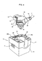
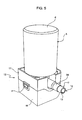
- Number 1 in Figure 1 indicates as a whole a kit for repairing and inflating inflatable articles, and comprising an outer casing 2; a compressor assembly C (shown schematically in Figure 2 ) housed inside outer casing 2; and a canister assembly 3 connected releasably to compressor assembly C.
- outer casing 2 comprises a substantially parallelepiped-shaped portion 4 housing compressor assembly C; and a projecting portion 5 projecting from the end of portion 4 to define a seat at least partly housing canister assembly 3.
- Canister assembly 3 contains sealing fluid for repairing a flat tyre, and comprises a bottle 6 positioned upside down in use; and a hose 7 connected to bottle 6 to feed sealing fluid into the tyre.
- Kit 1 also comprises a second hose 8 connected directly to compressor assembly C to inflate the tyre without injecting sealing fluid; and control means for selecting a repair mode in which hose 7 and bottle 6 are connected to compressor assembly C, and an inflation mode in which hose 8 is connected to compressor assembly C.
- the control means comprise a valve switchable by a knob 9 on casing 2, and having two outlets connected to canister assembly 3 and hose 8 respectively.
- Kit 1 also comprises an electronic control device 50 ( Figure 2 ) for turning compressor C of kit 1 on and off, in particular by means of a safety device.
- the electronic device comprises : a first and second power input IN AL 1, 2 connected, in use, to a power plug 10, and in particular connected respectively to a power line at a supply voltage, for example, of 12 V, and to a ground line; a first and second control input IN 1, 2 connected to a main switch 11 of electronic control device 50; a third and fourth control input IN 3, 4 connected to a safety device of kit 1; a fifth and sixth control input IN 5, 6 connected to a selector in turn connected functionally to knob 9; and a first and second output connected to compressor assembly C of kit 1, and in particular to respective first and second power inputs.
- the safety device of kit 1 is electrical, and is fitted to a connecting device 12 connected to hose 7 and for connecting hose 7 releasably to the safety valve of the tyre.
- the safety device comprises a contact sensor 51 which acts as a switch and preferably comprises a movable member held in an open-switch position by an elastic member (not shown), and a first and second electric conductor 13, 14 ( Figure 3 ) connected to the terminals of contact sensor 51, preferably inside connecting device 12 (and to the third and fourth control input IN 3, 4 of electronic control device 50), and located along, e.g. inside, hose 7.
- a contact sensor 51 which acts as a switch and preferably comprises a movable member held in an open-switch position by an elastic member (not shown), and a first and second electric conductor 13, 14 ( Figure 3 ) connected to the terminals of contact sensor 51, preferably inside connecting device 12 (and to the third and fourth control input IN 3, 4 of electronic control device 50), and located along, e.g. inside, hose 7.
- the electronic device also comprises:
- Figure 3 shows a releasable connecting device 15 mounted inside projecting portion 5 of casing 2 to connect compressor assembly C to canister assembly 3, and which comprises a base 16 connected rigidly to projecting portion 5; and a guide member 17 mounted on base 16 to form a single module by which to connect bottle 6 fluidically to compressor assembly C, and canister assembly 3 mechanically to casing 2.
- Base 16 and guide device 17 form a compact parallelepiped, and define a cavity 18 which is open on the side facing canister assembly 3, extends along an axis A, and is connected fluidically to compressor assembly C and to the valve switched by knob 9 by a conduit defined at least partly by base 16.
- a lock member 19 is mounted between base 16 and guide member 17, is movable crosswise to axis A, and is loaded by elastic means S into a position engaging canister assembly 3 inside cavity 18 to prevent movement of canister assembly 3 along axis A (position shown in Figure 3 ).
- Base 16 and guide member 17 define two through holes 20, 21 housing in sliding manner respective ejector devices 22, 23 by which to expel canister assembly 3 when the user presses lock member 19, in opposition to elastic means S, by means of a push-button P.
- Each ejector device comprises a straight rod 24 parallel to axis A; a supporting insert 25 connected rigidly to rod 24; and a spring M fitted to base 16 to hold supporting insert 25 in a predetermined position.
- the supporting insert comprises a flange 25a resting against guide member 17 to define the predetermined position; and a portion 25b having a non-circular cross section negatively reproduced by the relative hole 20, 21 to prevent rotation of rod 24.
- Rods 24 are of such a length as to project, parallel to axis A, with respect to guide member 17 when canister assembly 3 is not connected to releasable connecting device 15.
- rods 24 are made of conducting material, are of such a length as to project from respective holes 20, 21 on the opposite side of guide member 17 to canister assembly 3, and are connected to two terminals of the electronic device of kit 1.
- releasable connecting device 15 cooperates with a connecting member 25 of canister assembly 3 ( Figures 3 , 4 ) connected rigidly to bottle 6 and cooperating inside cavity 18 with lock member 19 to lock canister assembly to base 16, and with guide member 17 to prevent movement in a plane perpendicular to axis A.
- connecting member 25 is designed to connect to base 16 in a one-way movement - in the example shown, in a direction parallel to axis A.
- Connecting member 25 defines an inlet 26 connected fluidically to compressor assembly C by the conduit defined by base 16; and an outlet 27 connected to hose 7. More specifically, inlet 26 is connected to outlet 27 via the inside of bottle 6 to define a predetermined flow path for the compressed air generated by compressor assembly C when injecting sealing fluid into the tyre.
- the predetermined flow path conveniently extends through a valve (not shown) housed inside bottle 6 to open outlet 27 and control the pressure of bottle 6 and outflow of the sealing fluid along hose 7.
- the valve is as described in International Patent Application WO-A-2005084968 filed by the present Applicant.
- inlet 26 is coaxial with axis A, and is carried by a tubular body 28 approximating but no larger than a portion of cavity 18 defined by guide member 17, so as to secure canister assembly 3 in directions perpendicular to axis A. More specifically, tubular body 28 defines a cavity K housing the neck (not shown) of bottle 6.
- Outlet 27 is crosswise to axis A, and is defined by a tubular member having an inverted-pine-shaped outer profile for connection to hose 7 made of polymer material.
- Connecting member 25 supports two conductors 29, 30 preferably defined by contoured metal strips and comprising respective end portions 31, 32 alongside outlet 17. Each conductor 29, 30 also comprises a second end portion 33 (only one shown in Figure 4 ) fitted to a wall 35 projecting, crosswise to axis A, from tubular body 28, so that end portions 33 cooperate with rods 24 and connect contact sensor 51 to electronic device 50 when canister assembly 3 is connected to connecting device 15.
- contact sensor 51 is connected to conductors 29, 30 by conductors 13, 14 defined, for example, by metal wires fitted inside hose 7 and having respective end portions 13a, 14a bent outwards at an end portion 37 of the hose, as shown in Figure 4 .
- Hose 7 is thus secured by radial interference to the tubular portion defining outlet 27, conductors 13 and 14 being interposed radially between end portion 37 and the tubular portion defining outlet 27.
- end portions 31, 32 project from tubular body 28, and are flexible to apply sufficient pressure to ensure reliable electrical contact between end portions 13a, 14a and conductors 29, 30.
- End portions 31, 32 are covered and protected by a sleeve 38 preferably made of heat-shrink polymer material.
- knob 9 when knob 9 is set to repair mode, the electronic control device determines the chosen mode and only enables compressor assembly C when rods 24 are short-circuited by contact sensor 51, which only closes when hose 7 is connected properly to the safety valve of the tyre.
- connecting device 12 when the, for example threaded, connecting device 12 is screwed to the safety valve, the movable member comes to rest against the valve and withdraws to short-circuit conductors 13, 14.
- knob 9 When knob 9 is set to inflation mode, the electronic control device determines the chosen mode and disables contact sensor 51, so that compressor assembly C is activated when main switch 11 is closed, and is deactivated when main switch 11 is opened.
- main switch 11 is movable between an open position and a closed position, and is designed to return automatically to the open position when pressed by the user, so that accidental pressure, before power plug 10 is connected to the current outlet, does not maintain the closed position. On the contrary, the open position is immediately restored, so that compressor assembly C is only activated by the user pressing main switch 11 after connecting power plug 10 to the current outlet. This therefore prevents compressor assembly C from being activated while connecting power plug 10 to the current outlet.
- Main switch 11, for example, is electronic.
- first control unit 54 is equipped internally with a logic memory element (e.g. a flip-flop), and is configured (in a manner not described in detail but obvious to an expert) to switch the high/low value of a control signal supplied to the control terminal of turn-on switch 53 whenever main switch 11 is pressed by the user. If the control signal is of such a value, e.g. high, as to close turn-on switch 53, compressor assembly C is activated (by virtue of the closed turn-on switch connecting the second output electrically to the ground line).
- a logic memory element e.g. a flip-flop
- enabling switch 53 (normally closed to disable the compressor assembly) is opened by enabling stage 55, thus enabling turn-on stage 52, both in response to closure of the knob 9 selector (indicating inflation mode selection by the user), and in response to closure of contact sensor 51, but only if the knob 9 selector is open (indicating repair mode selection by the user).
- closure of the selector actually disables contact sensor 51, and contact sensor 51 only intervenes in the electronic control device when the selector is open.
- Electric contact between canister assembly 3 and the electronic device is ensured by the ends of rods 24 contacting relative conductors 29, 30, and is improved by the force exerted by springs M which are movable to take up any slack.
- button P of lock member 19 when button P of lock member 19 is pressed by the user, springs M assist expulsion, and so simplify replacement, of canister assembly 3.
- kit 1 as described above are as follows.
- Contact sensor 51 connected to contacts 33 supplies a signal to only turn on compressor assembly C when hose 7 is connected to the tyre and knob 9 is set to repair mode.
- Spring-loaded rods 24, movable in the assembly direction of canister assembly 3, ensure reliable electric contact by means of springs M, and also act as an ejector device to expel canister assembly 3 when button P is pressed.
- Electric contacts 33 are fitted to wall 35 to cooperate easily and effectively with, i.e. the ends of, rods 24.
- kit 1 as described and illustrated herein without, however, departing from the scope of the present invention as defined in the accompanying Claims.
- conductors 29, 30 may be molded on, so that at least end portions 31, 32, 33 are exposed for electric connection to conductors 13, 14 and rods 24.
- Base 16 may comprise a non-return valve by which to disconnect cavity 18 from compressor assembly C when canister assembly 3 is removed from base 16, and which is preferably controlled to open automatically when canister assembly 3 is fitted to base 16.
- the electronic circuit described and illustrated may be fitted to a kit comprising releasable connecting means and/or a canister assembly with a safety device for short-circuiting conductors 29, 30 other than those illustrated.
Landscapes
- Engineering & Computer Science (AREA)
- Mechanical Engineering (AREA)
- Pipe Accessories (AREA)
- Telephone Function (AREA)
- Medical Preparation Storing Or Oral Administration Devices (AREA)
- Manipulator (AREA)
Claims (12)
- Kit pour réparer et gonfler des articles gonflables, comprenant un ensemble de compresseur (C) ; un ensemble de cartouche (3) contenant un fluide d'étanchéité ; et des moyens de connexion détachables (16, 17) définissant une direction d'assemblage (A) et pour connecter ledit ensemble de compresseur (C) audit ensemble de cartouche (3) ; le kit étant caractérisé en ce qu'il comprend un dispositif de commande pour commander l'activation dudit ensemble de compresseur (C), et au moins une borne électrique mobile (24) connectée audit dispositif de commande et chargée élastiquement dans une position prédéterminée ; et en ce que ledit ensemble de cartouche (3) comprend un capteur (51) et au moins un contact électrique (33) connecté audit capteur (51) et coopérant avec ladite borne électrique mobile (24) pour transmettre un signal dudit capteur (51) audit dispositif de commande quand ledit ensemble de cartouche (3) est connecté à un article gonflable ; ladite borne électrique mobile (24) étant conçue pour exercer une force sur ledit ensemble de cartouche (3) pour déplacer ledit ensemble de cartouche (3) dans ladite direction d'assemblage (A) quand lesdits moyens de connexion détachables (16, 17) sont libérés.
- Kit selon la revendication 1, caractérisé en ce que ladite au moins une borne mobile (24) est mobile parallèlement à ladite direction d'assemblage (A) ; et ledit au moins un contact électrique (33) est fixé à une paroi (35) transversalement à ladite direction d'assemblage (A).
- Kit selon la revendication 1 ou 2, caractérisé en ce qu'il comprend un boîtier (2) et en ce que lesdits moyens de connexion détachables (16, 17) comprennent un module (26, 27) connecté de manière rigide audit boîtier (2) et définissant une cavité (18) connectée en communication fluidique avec ledit ensemble de compresseur (C), et au moins un siège (20 ; 21) pour ladite borne électrique mobile (24).
- Kit selon l'une quelconque des revendications précédentes, caractérisé en ce que ledit ensemble de cartouche (3) comprend un tube (7) délivrant ledit fluide d'étanchéité et supportant ledit capteur (51) ; une unité de connexion (25) avec laquelle engager lesdits moyens de connexion détachables (16, 17) ; au moins un premier conducteur électrique (13 ; 14) supporté par ledit tube (7) et connecté audit capteur (51) ; et au moins un deuxième conducteur électrique (29 ; 30) ayant une première portion (33) définissant un contact électrique coopérant avec ladite borne électrique mobile (24) quand ledit ensemble de cartouche (3) est fixé auxdits moyens de connexion détachables (16, 17) ; ledit deuxième conducteur électrique (29 ; 30) comprenant une deuxième portion (31 ; 32) connectée électriquement à une portion terminale (13a ; 14a) dudit premier conducteur électrique (13 ; 14).
- Kit selon la revendication 4, caractérisé en ce que ladite première portion (33) et ladite deuxième portion (31 ; 32) sont espacées dans ladite direction d'assemblage (A).
- Kit selon la revendication 4 ou 5, caractérisé en ce que ladite deuxième portion (31 ; 32) est située le long dudit tube (7).
- Ensemble de cartouche, pour un fluide d'étanchéité, pouvant être connecté à un ensemble de compresseur (C) et comprenant une unité de connexion (25) définissant une direction d'assemblage (A) et coopérant avec des moyens de connexion détachables (16, 17) connectés audit ensemble de compresseur (C) ; l'ensemble de cartouche étant caractérisé en ce qu'il comprend un capteur (51) ; et au moins un contact électrique (33) connecté audit capteur (51) et coopérant avec une borne électrique mobile (24) pour transmettre un signal dudit capteur (51) à un dispositif de commande quand ledit ensemble de cartouche (3) est connecté à un article gonflable ; ledit contact électrique (33) étant positionné, par rapport à ladite direction d'assemblage (A), de manière à être mis en contact avec ladite borne électrique mobile (24) pour transmettre une force élastique audit ensemble de cartouche (3) pour déplacer ledit ensemble de cartouche (3) dans ladite direction d'assemblage (A) quand lesdits moyens de connexion détachables (16, 17) sont libérés.
- Ensemble de cartouche selon la revendication 7, caractérisé en ce que ledit contact électrique (33) est fixé à une paroi (35) transversalement à ladite direction d'assemblage.
- Ensemble de cartouche selon la revendication 7 ou 8, caractérisé en ce qu'il comprend un tube (7) délivrant ledit fluide d'étanchéité et supportant ledit capteur (51) ; au moins un premier conducteur électrique (13 ; 14) supporté par ledit tube (7) et connecté audit capteur (51) ; ; et au moins un deuxième conducteur élec(-trique (29 ; 30) ayant une première portion (33) définissant un contact électrique et coopérant avec ladite borne électrique mobile (24) quand ledit ensemble de cartouche (3) est fixé auxdits moyens de connexion détachables (16, 17) ; ledit deuxième conducteur électrique (29 ; 30) comprenant une deuxième portion (31 ; 32) connectée électriquement à une portion terminale (13a ; 14a) dudit premier conducteur électrique (13 ; 14).
- Ensemble de cartouche selon la revendication 9, caractérisé en ce que ladite première portion (33) et ladite deuxième portion (31 ; 32) sont espacées dans ladite direction d'assemblage (A).
- Ensemble de cartouche selon la revendication 9 ou 10, caractérisé en ce que ladite deuxième portion (31 ; 32) est située le long dudit tube (7).
- Ensemble de cartouche selon l'une quelconque des revendications 7 à 11, caractérisé en ce qu'il définit un volume (V) pour le fluide d'étanchéité ; et en ce que ladite unité de connexion (25) est au-dessous dudit volume (V) dans ladite direction d'assemblage (A).
Applications Claiming Priority (2)
| Application Number | Priority Date | Filing Date | Title |
|---|---|---|---|
| IT000591A ITTO20070591A1 (it) | 2007-08-08 | 2007-08-08 | Kit per la riparazione e il gonfiaggio di articoli gonfiabili provvisto di un dispositivo di controllo e relativo gruppo contenitore |
| PCT/IB2008/002091 WO2009019590A2 (fr) | 2007-08-08 | 2008-08-08 | Ensemble, équipé d'un dispositif de commande, pour réparer et gonfler des articles gonflables, et ensemble de cartouche associé |
Publications (2)
| Publication Number | Publication Date |
|---|---|
| EP2185347A2 EP2185347A2 (fr) | 2010-05-19 |
| EP2185347B1 true EP2185347B1 (fr) | 2011-11-30 |
Family
ID=40227720
Family Applications (1)
| Application Number | Title | Priority Date | Filing Date |
|---|---|---|---|
| EP08789041A Not-in-force EP2185347B1 (fr) | 2007-08-08 | 2008-08-08 | Ensemble, équipé d'un dispositif de commande, pour réparer et gonfler des articles gonflables, et ensemble de cartouche associé |
Country Status (7)
| Country | Link |
|---|---|
| US (1) | US8491275B2 (fr) |
| EP (1) | EP2185347B1 (fr) |
| CN (1) | CN101821082B (fr) |
| AT (1) | ATE535366T1 (fr) |
| BR (1) | BRPI0816472A8 (fr) |
| IT (1) | ITTO20070591A1 (fr) |
| WO (1) | WO2009019590A2 (fr) |
Families Citing this family (15)
| Publication number | Priority date | Publication date | Assignee | Title |
|---|---|---|---|---|
| ITTO20040117A1 (it) * | 2004-02-27 | 2004-05-27 | Tek Srl | Kit per il gonfiaggio e la riparazione di articoli gonfiabili, in particolare pneumatici |
| US8146622B2 (en) | 2007-08-20 | 2012-04-03 | Ford Global Technologies, Llc | Switch and hose-valve connection arrangement for vehicle temporary mobility kit |
| US8517760B2 (en) | 2007-08-20 | 2013-08-27 | Ford Global Technologies, Llc | Cord wrap and power plug receptacle arrangement for inflator |
| US8276624B2 (en) | 2008-01-31 | 2012-10-02 | Ford Global Technologies, Llc | Sealant bottle snap-in feature for vehicle temporary mobility kit |
| US8115615B2 (en) | 2007-09-08 | 2012-02-14 | Ford Global Technologies | Status indicator and reminder system for vehicle temporary mobility kit |
| ITTO20070610A1 (it) * | 2007-08-28 | 2009-02-28 | Tek Global Srl | Gruppo contenitore di liquido sigillante e kit per la riparazione e il gonfiaggio di articoli gonfiabili provvisto di un tale contenitore |
| US8981921B2 (en) | 2007-09-08 | 2015-03-17 | Ford Global Technologies, Llc | Status indicator and reminder system for vehicle temporary mobility kit |
| ITTO20090400A1 (it) * | 2009-05-26 | 2010-11-27 | Tek Global Srl | Kit-semiautomatico per la riparazione e il gonfiaggio di articoli gonfiabili perfezionato |
| TWI460089B (zh) * | 2011-09-23 | 2014-11-11 | Wen San Chou | Air compressor for vehicle |
| US8746293B2 (en) * | 2011-10-12 | 2014-06-10 | Wen San Chou | Device for sealing and inflating inflatable object |
| US9458002B2 (en) * | 2014-04-11 | 2016-10-04 | Suss Microtec Lithography Gmbh | Bottle supply system and bottle cap adapter |
| ITUA20164201A1 (it) * | 2016-06-08 | 2017-12-08 | Tek Global Srl | Contenitore sensorizzato di liquido sigillante e kit di riparazione per articoli gonfiabili con tale contenitore |
| CN110267830A (zh) * | 2016-12-15 | 2019-09-20 | 冠翔(香港)工业有限公司 | 轮胎维护装置 |
| USD914769S1 (en) * | 2018-11-30 | 2021-03-30 | Tek Global S.R.L. | Tire sealing and inflation device |
| TWI789787B (zh) | 2021-06-16 | 2023-01-11 | 周文三 | 一種使用方法可對汽車輪胎進行多樣化充氣及補胎的急救裝置 |
Family Cites Families (5)
| Publication number | Priority date | Publication date | Assignee | Title |
|---|---|---|---|---|
| ITTO20040121A1 (it) | 2004-02-27 | 2004-05-27 | Tek Srl | Contenitore per un liquido sigillante per la riparazione di oggetti gonfiabili, in particolare pnematici, e kit di riparazione provvisto di tale contenitore |
| EP1747878A4 (fr) | 2004-05-20 | 2010-10-13 | Bridgestone Corp | Dispositif verseur d'agent d'étanchéité, méthode pour verser un agent d'étanchéité et dispositif de pompage d'agent d'étanchéité |
| US7891385B2 (en) * | 2004-05-27 | 2011-02-22 | Bridgestone Corporation | Sealing pump-up device |
| DE102004042911A1 (de) * | 2004-09-02 | 2006-03-09 | Michael Stehle | Vorrichtung zum Ausbringen von Luft- und/oder Reifendichtmittel |
| ITTO20060454A1 (it) * | 2006-06-20 | 2007-12-21 | Tek Srl | Kit per la riparazione e il gonfiaggio di articoli gonfiabili |
-
2007
- 2007-08-08 IT IT000591A patent/ITTO20070591A1/it unknown
-
2008
- 2008-08-08 WO PCT/IB2008/002091 patent/WO2009019590A2/fr active Application Filing
- 2008-08-08 BR BRPI0816472A patent/BRPI0816472A8/pt not_active IP Right Cessation
- 2008-08-08 AT AT08789041T patent/ATE535366T1/de active
- 2008-08-08 US US12/672,412 patent/US8491275B2/en not_active Expired - Fee Related
- 2008-08-08 EP EP08789041A patent/EP2185347B1/fr not_active Not-in-force
- 2008-08-08 CN CN2008801105681A patent/CN101821082B/zh not_active Expired - Fee Related
Also Published As
| Publication number | Publication date |
|---|---|
| US8491275B2 (en) | 2013-07-23 |
| ATE535366T1 (de) | 2011-12-15 |
| BRPI0816472A2 (pt) | 2015-03-17 |
| ITTO20070591A1 (it) | 2009-02-09 |
| CN101821082A (zh) | 2010-09-01 |
| EP2185347A2 (fr) | 2010-05-19 |
| WO2009019590A2 (fr) | 2009-02-12 |
| WO2009019590A3 (fr) | 2009-04-02 |
| US20110116941A1 (en) | 2011-05-19 |
| BRPI0816472A8 (pt) | 2018-12-18 |
| CN101821082B (zh) | 2013-11-13 |
Similar Documents
| Publication | Publication Date | Title |
|---|---|---|
| EP2185347B1 (fr) | Ensemble, équipé d'un dispositif de commande, pour réparer et gonfler des articles gonflables, et ensemble de cartouche associé | |
| US8997802B2 (en) | Sealing fluid container assembly, and kit for repairing and inflating inflatable articles and equipped with such a container | |
| CN101437669B (zh) | 用于可充气物品的修复和充气且具有选择阀的自动装备 | |
| EP2058112B1 (fr) | Kit pour la réparation et le gonflage d'articles gonflables, et doté d'un dispositif de commande | |
| US8181676B2 (en) | Temporary mobility kit with inadvertant flow prevention techniques | |
| US4661060A (en) | Dental handpiece | |
| US7182280B2 (en) | DC power spraying tool | |
| US20070104592A1 (en) | Inflating/deflating device for an inflatable | |
| GB2360941A (en) | Airbed with built-in battery case and socket | |
| JP2010503551A (ja) | 可膨張式品物の修理用および空気注入用のキット | |
| KR20210021986A (ko) | 전력 공급 데이터 포트용의 차량 타이어 팽창용 압축기 | |
| US9309990B2 (en) | Pressure gauge device featuring setting for automatic supply and termination of pressure | |
| GB2428751A (en) | Inflating/deflating device for an inflatable mattress | |
| JP2010173118A (ja) | パンク修理装置 | |
| CN101396950B (zh) | 用于可充气物品的维修及充气的设备及该设备的容器组件 | |
| JPH09192044A (ja) | 水 栓 | |
| KR20070055008A (ko) | 차량의 암전류 차단용 파워커넥터 착탈장치 | |
| WO2012007188A1 (fr) | Changeur d'outil pour environnement explosif |
Legal Events
| Date | Code | Title | Description |
|---|---|---|---|
| PUAI | Public reference made under article 153(3) epc to a published international application that has entered the european phase |
Free format text: ORIGINAL CODE: 0009012 |
|
| 17P | Request for examination filed |
Effective date: 20100227 |
|
| AK | Designated contracting states |
Kind code of ref document: A2 Designated state(s): AT BE BG CH CY CZ DE DK EE ES FI FR GB GR HR HU IE IS IT LI LT LU LV MC MT NL NO PL PT RO SE SI SK TR |
|
| AX | Request for extension of the european patent |
Extension state: AL BA MK RS |
|
| GRAP | Despatch of communication of intention to grant a patent |
Free format text: ORIGINAL CODE: EPIDOSNIGR1 |
|
| DAX | Request for extension of the european patent (deleted) | ||
| GRAS | Grant fee paid |
Free format text: ORIGINAL CODE: EPIDOSNIGR3 |
|
| GRAA | (expected) grant |
Free format text: ORIGINAL CODE: 0009210 |
|
| AK | Designated contracting states |
Kind code of ref document: B1 Designated state(s): AT BE BG CH CY CZ DE DK EE ES FI FR GB GR HR HU IE IS IT LI LT LU LV MC MT NL NO PL PT RO SE SI SK TR |
|
| REG | Reference to a national code |
Ref country code: CH Ref legal event code: EP Ref country code: GB Ref legal event code: FG4D |
|
| REG | Reference to a national code |
Ref country code: IE Ref legal event code: FG4D |
|
| REG | Reference to a national code |
Ref country code: DE Ref legal event code: R096 Ref document number: 602008011744 Country of ref document: DE Effective date: 20120301 |
|
| REG | Reference to a national code |
Ref country code: NL Ref legal event code: VDEP Effective date: 20111130 |
|
| LTIE | Lt: invalidation of european patent or patent extension |
Effective date: 20111130 |
|
| PG25 | Lapsed in a contracting state [announced via postgrant information from national office to epo] |
Ref country code: LT Free format text: LAPSE BECAUSE OF FAILURE TO SUBMIT A TRANSLATION OF THE DESCRIPTION OR TO PAY THE FEE WITHIN THE PRESCRIBED TIME-LIMIT Effective date: 20111130 Ref country code: IS Free format text: LAPSE BECAUSE OF FAILURE TO SUBMIT A TRANSLATION OF THE DESCRIPTION OR TO PAY THE FEE WITHIN THE PRESCRIBED TIME-LIMIT Effective date: 20120330 Ref country code: NO Free format text: LAPSE BECAUSE OF FAILURE TO SUBMIT A TRANSLATION OF THE DESCRIPTION OR TO PAY THE FEE WITHIN THE PRESCRIBED TIME-LIMIT Effective date: 20120229 |
|
| PG25 | Lapsed in a contracting state [announced via postgrant information from national office to epo] |
Ref country code: PT Free format text: LAPSE BECAUSE OF FAILURE TO SUBMIT A TRANSLATION OF THE DESCRIPTION OR TO PAY THE FEE WITHIN THE PRESCRIBED TIME-LIMIT Effective date: 20120330 Ref country code: NL Free format text: LAPSE BECAUSE OF FAILURE TO SUBMIT A TRANSLATION OF THE DESCRIPTION OR TO PAY THE FEE WITHIN THE PRESCRIBED TIME-LIMIT Effective date: 20111130 Ref country code: LV Free format text: LAPSE BECAUSE OF FAILURE TO SUBMIT A TRANSLATION OF THE DESCRIPTION OR TO PAY THE FEE WITHIN THE PRESCRIBED TIME-LIMIT Effective date: 20111130 Ref country code: HR Free format text: LAPSE BECAUSE OF FAILURE TO SUBMIT A TRANSLATION OF THE DESCRIPTION OR TO PAY THE FEE WITHIN THE PRESCRIBED TIME-LIMIT Effective date: 20111130 Ref country code: BE Free format text: LAPSE BECAUSE OF FAILURE TO SUBMIT A TRANSLATION OF THE DESCRIPTION OR TO PAY THE FEE WITHIN THE PRESCRIBED TIME-LIMIT Effective date: 20111130 Ref country code: GR Free format text: LAPSE BECAUSE OF FAILURE TO SUBMIT A TRANSLATION OF THE DESCRIPTION OR TO PAY THE FEE WITHIN THE PRESCRIBED TIME-LIMIT Effective date: 20120301 Ref country code: SI Free format text: LAPSE BECAUSE OF FAILURE TO SUBMIT A TRANSLATION OF THE DESCRIPTION OR TO PAY THE FEE WITHIN THE PRESCRIBED TIME-LIMIT Effective date: 20111130 Ref country code: SE Free format text: LAPSE BECAUSE OF FAILURE TO SUBMIT A TRANSLATION OF THE DESCRIPTION OR TO PAY THE FEE WITHIN THE PRESCRIBED TIME-LIMIT Effective date: 20111130 |
|
| PG25 | Lapsed in a contracting state [announced via postgrant information from national office to epo] |
Ref country code: CY Free format text: LAPSE BECAUSE OF FAILURE TO SUBMIT A TRANSLATION OF THE DESCRIPTION OR TO PAY THE FEE WITHIN THE PRESCRIBED TIME-LIMIT Effective date: 20111130 |
|
| PG25 | Lapsed in a contracting state [announced via postgrant information from national office to epo] |
Ref country code: BG Free format text: LAPSE BECAUSE OF FAILURE TO SUBMIT A TRANSLATION OF THE DESCRIPTION OR TO PAY THE FEE WITHIN THE PRESCRIBED TIME-LIMIT Effective date: 20120229 Ref country code: SK Free format text: LAPSE BECAUSE OF FAILURE TO SUBMIT A TRANSLATION OF THE DESCRIPTION OR TO PAY THE FEE WITHIN THE PRESCRIBED TIME-LIMIT Effective date: 20111130 Ref country code: EE Free format text: LAPSE BECAUSE OF FAILURE TO SUBMIT A TRANSLATION OF THE DESCRIPTION OR TO PAY THE FEE WITHIN THE PRESCRIBED TIME-LIMIT Effective date: 20111130 Ref country code: DK Free format text: LAPSE BECAUSE OF FAILURE TO SUBMIT A TRANSLATION OF THE DESCRIPTION OR TO PAY THE FEE WITHIN THE PRESCRIBED TIME-LIMIT Effective date: 20111130 Ref country code: CZ Free format text: LAPSE BECAUSE OF FAILURE TO SUBMIT A TRANSLATION OF THE DESCRIPTION OR TO PAY THE FEE WITHIN THE PRESCRIBED TIME-LIMIT Effective date: 20111130 |
|
| PG25 | Lapsed in a contracting state [announced via postgrant information from national office to epo] |
Ref country code: PL Free format text: LAPSE BECAUSE OF FAILURE TO SUBMIT A TRANSLATION OF THE DESCRIPTION OR TO PAY THE FEE WITHIN THE PRESCRIBED TIME-LIMIT Effective date: 20111130 Ref country code: RO Free format text: LAPSE BECAUSE OF FAILURE TO SUBMIT A TRANSLATION OF THE DESCRIPTION OR TO PAY THE FEE WITHIN THE PRESCRIBED TIME-LIMIT Effective date: 20111130 |
|
| REG | Reference to a national code |
Ref country code: AT Ref legal event code: MK05 Ref document number: 535366 Country of ref document: AT Kind code of ref document: T Effective date: 20111130 |
|
| PLBE | No opposition filed within time limit |
Free format text: ORIGINAL CODE: 0009261 |
|
| STAA | Information on the status of an ep patent application or granted ep patent |
Free format text: STATUS: NO OPPOSITION FILED WITHIN TIME LIMIT |
|
| 26N | No opposition filed |
Effective date: 20120831 |
|
| REG | Reference to a national code |
Ref country code: DE Ref legal event code: R097 Ref document number: 602008011744 Country of ref document: DE Effective date: 20120831 |
|
| PG25 | Lapsed in a contracting state [announced via postgrant information from national office to epo] |
Ref country code: AT Free format text: LAPSE BECAUSE OF FAILURE TO SUBMIT A TRANSLATION OF THE DESCRIPTION OR TO PAY THE FEE WITHIN THE PRESCRIBED TIME-LIMIT Effective date: 20111130 |
|
| REG | Reference to a national code |
Ref country code: CH Ref legal event code: PL |
|
| PG25 | Lapsed in a contracting state [announced via postgrant information from national office to epo] |
Ref country code: MC Free format text: LAPSE BECAUSE OF NON-PAYMENT OF DUE FEES Effective date: 20120831 |
|
| GBPC | Gb: european patent ceased through non-payment of renewal fee |
Effective date: 20120808 |
|
| PG25 | Lapsed in a contracting state [announced via postgrant information from national office to epo] |
Ref country code: LI Free format text: LAPSE BECAUSE OF NON-PAYMENT OF DUE FEES Effective date: 20120831 Ref country code: CH Free format text: LAPSE BECAUSE OF NON-PAYMENT OF DUE FEES Effective date: 20120831 Ref country code: ES Free format text: LAPSE BECAUSE OF FAILURE TO SUBMIT A TRANSLATION OF THE DESCRIPTION OR TO PAY THE FEE WITHIN THE PRESCRIBED TIME-LIMIT Effective date: 20120311 |
|
| REG | Reference to a national code |
Ref country code: FR Ref legal event code: ST Effective date: 20130430 |
|
| REG | Reference to a national code |
Ref country code: IE Ref legal event code: MM4A |
|
| PG25 | Lapsed in a contracting state [announced via postgrant information from national office to epo] |
Ref country code: FI Free format text: LAPSE BECAUSE OF FAILURE TO SUBMIT A TRANSLATION OF THE DESCRIPTION OR TO PAY THE FEE WITHIN THE PRESCRIBED TIME-LIMIT Effective date: 20111130 |
|
| PG25 | Lapsed in a contracting state [announced via postgrant information from national office to epo] |
Ref country code: IE Free format text: LAPSE BECAUSE OF NON-PAYMENT OF DUE FEES Effective date: 20120808 Ref country code: GB Free format text: LAPSE BECAUSE OF NON-PAYMENT OF DUE FEES Effective date: 20120808 |
|
| PG25 | Lapsed in a contracting state [announced via postgrant information from national office to epo] |
Ref country code: FR Free format text: LAPSE BECAUSE OF NON-PAYMENT OF DUE FEES Effective date: 20120831 |
|
| PG25 | Lapsed in a contracting state [announced via postgrant information from national office to epo] |
Ref country code: MT Free format text: LAPSE BECAUSE OF FAILURE TO SUBMIT A TRANSLATION OF THE DESCRIPTION OR TO PAY THE FEE WITHIN THE PRESCRIBED TIME-LIMIT Effective date: 20111130 |
|
| PG25 | Lapsed in a contracting state [announced via postgrant information from national office to epo] |
Ref country code: TR Free format text: LAPSE BECAUSE OF FAILURE TO SUBMIT A TRANSLATION OF THE DESCRIPTION OR TO PAY THE FEE WITHIN THE PRESCRIBED TIME-LIMIT Effective date: 20111130 |
|
| PG25 | Lapsed in a contracting state [announced via postgrant information from national office to epo] |
Ref country code: LU Free format text: LAPSE BECAUSE OF NON-PAYMENT OF DUE FEES Effective date: 20120808 |
|
| PG25 | Lapsed in a contracting state [announced via postgrant information from national office to epo] |
Ref country code: HU Free format text: LAPSE BECAUSE OF FAILURE TO SUBMIT A TRANSLATION OF THE DESCRIPTION OR TO PAY THE FEE WITHIN THE PRESCRIBED TIME-LIMIT Effective date: 20080808 |
|
| PGFP | Annual fee paid to national office [announced via postgrant information from national office to epo] |
Ref country code: IT Payment date: 20160808 Year of fee payment: 9 |
|
| PGFP | Annual fee paid to national office [announced via postgrant information from national office to epo] |
Ref country code: DE Payment date: 20171030 Year of fee payment: 10 |
|
| PG25 | Lapsed in a contracting state [announced via postgrant information from national office to epo] |
Ref country code: IT Free format text: LAPSE BECAUSE OF NON-PAYMENT OF DUE FEES Effective date: 20170808 |
|
| REG | Reference to a national code |
Ref country code: DE Ref legal event code: R119 Ref document number: 602008011744 Country of ref document: DE |
|
| PG25 | Lapsed in a contracting state [announced via postgrant information from national office to epo] |
Ref country code: DE Free format text: LAPSE BECAUSE OF NON-PAYMENT OF DUE FEES Effective date: 20190301 |