EP2185318B1 - Tourelle revolver - Google Patents
Tourelle revolver Download PDFInfo
- Publication number
- EP2185318B1 EP2185318B1 EP08785588A EP08785588A EP2185318B1 EP 2185318 B1 EP2185318 B1 EP 2185318B1 EP 08785588 A EP08785588 A EP 08785588A EP 08785588 A EP08785588 A EP 08785588A EP 2185318 B1 EP2185318 B1 EP 2185318B1
- Authority
- EP
- European Patent Office
- Prior art keywords
- tool
- disc
- coupling
- gear head
- drive
- Prior art date
- Legal status (The legal status is an assumption and is not a legal conclusion. Google has not performed a legal analysis and makes no representation as to the accuracy of the status listed.)
- Not-in-force
Links
Images

Classifications
-
- B—PERFORMING OPERATIONS; TRANSPORTING
- B23—MACHINE TOOLS; METAL-WORKING NOT OTHERWISE PROVIDED FOR
- B23Q—DETAILS, COMPONENTS, OR ACCESSORIES FOR MACHINE TOOLS, e.g. ARRANGEMENTS FOR COPYING OR CONTROLLING; MACHINE TOOLS IN GENERAL CHARACTERISED BY THE CONSTRUCTION OF PARTICULAR DETAILS OR COMPONENTS; COMBINATIONS OR ASSOCIATIONS OF METAL-WORKING MACHINES, NOT DIRECTED TO A PARTICULAR RESULT
- B23Q16/00—Equipment for precise positioning of tool or work into particular locations not otherwise provided for
- B23Q16/02—Indexing equipment
- B23Q16/021—Indexing equipment in which only the positioning elements are of importance
-
- B—PERFORMING OPERATIONS; TRANSPORTING
- B23—MACHINE TOOLS; METAL-WORKING NOT OTHERWISE PROVIDED FOR
- B23B—TURNING; BORING
- B23B29/00—Holders for non-rotary cutting tools; Boring bars or boring heads; Accessories for tool holders
- B23B29/24—Tool holders for a plurality of cutting tools, e.g. turrets
- B23B29/32—Turrets adjustable by power drive, i.e. turret heads
- B23B29/323—Turrets with power operated angular positioning devices
-
- B—PERFORMING OPERATIONS; TRANSPORTING
- B23—MACHINE TOOLS; METAL-WORKING NOT OTHERWISE PROVIDED FOR
- B23Q—DETAILS, COMPONENTS, OR ACCESSORIES FOR MACHINE TOOLS, e.g. ARRANGEMENTS FOR COPYING OR CONTROLLING; MACHINE TOOLS IN GENERAL CHARACTERISED BY THE CONSTRUCTION OF PARTICULAR DETAILS OR COMPONENTS; COMBINATIONS OR ASSOCIATIONS OF METAL-WORKING MACHINES, NOT DIRECTED TO A PARTICULAR RESULT
- B23Q2220/00—Machine tool components
- B23Q2220/002—Tool turrets
Definitions
- the invention relates to a tool turret with a base body to be mounted or attached to a machine tool, which defines a turret about which is rotatably mounted on the main body a tool disk having a plurality of distributed around its circumference tool stations, each adjustable by rotating the tool disk in at least one working position are in which a located inside the tool disk tool drive comes with its drive-side coupling part with a tool-side coupling part for driving a tool in clutch engagement, which is located on the aligned to the working position tool station, according to the feature configuration of the preamble of claim 1.
- Tool turrets of this type are known. For example, show the DE 689 08 208 T2 or DE 10 2005 033 890 A1 Tool turrets of this type, which are intended for use in machine tools, such as lathes, machining centers and similar devices. When using such tool turrets are located at the tool stations of the tool disk tools that are to be used, both stationary tools, such as turning tools and the like, as well as so-called. Rotary tools for machining operations, like drilling, milling and the like.
- the rotary drive for the rotary tool in question takes place; located at the tool station located in the working position, via the internal tool drive, with which a respective, tool-side coupling part can come into clutch engagement when the tool station on which the rotary tool is mounted, is in a defined working position.
- the determination of the angular position of the working position relative to the base body is disadvantageous in some cases. While a fixed angular position of the working position is appropriate for turning operations, because it always takes place on the center of the workpiece axis machining, it is often desirable to make outside the specified angular position drilling or milling can, the feed or machining direction is not rectangular takes place to the workpiece axis.
- a generic tool turret is known to be attached to a machine tool or placed on base body defining a turret about which is rotatably mounted on the main body a tool disk having a plurality of distributed around its circumference tool stations by rotating the tool disk in each case at least one working position are adjustable, in which a located inside the tool disk tool drive comes with its drive-side coupling part with a tool-side coupling part for driving a tool in clutch engagement, which is located on the aligned to the working position tool station, wherein the tool drive has a rotatably arranged in the Malawiusionidgetriebe gear head , Which is provided between a tool disc and gear head clutch is provided between a first switching position in which the gear head and the Tool disc are rotatably connected to each other, and a second switching position is reversible, in which the gear head is uncoupled from the tool disk and rotatably connected to the main body, wherein the clutch has a toothed clutch with clutch teeth
- the invention has the object to provide a tool turret, can be made with the machining operations using rotary tools not only when setting the tool disk to a defined working position, but also in such cases where the tool disk in a desired arbitrary rotational position is located.
- a significant feature of the invention is that provided for the coupling and decoupling of gear head and tool disc clutch teeth are arranged on the extending through the housing of the gear head front end portion of the shift shaft and with associated toothed seats at the front end portion of the tool disc and the adjacent front Housing part of the gear head in corresponding axial positions of the shift shaft in and disengageable,
- the clutch has a toothed coupling with clutch teeth, which connect the tool disc form-fitting manner with a housing part of the gear head in the first switching position.
- the clutch is actuated by a Heidelbergweile, concentric with the turret axis in the base body and in the tool disk axially between the first switching position and the second switching position corresponding positions is axially displaceable.
- the arrangement is in this case made such that the shift shaft in an area located within the body as part of the clutch has a one-way clutch forming, radially projecting clutch tooth, which comes in the second switching position in positive engagement with a tooth seat on the body and the rotationally fixed connection forms between gear head and body.
- the positional relationships between the coupling tooth of the single-tooth clutch and an associated tooth seat on the base body are selected such that the clutch tooth engages the tooth seat at a position of the gear head corresponding to an initial operating position.
- the switching shaft of a first hollow shaft mounted in the base body which is provided as a drive shaft of the gear head for the tool drive, and surrounded by a second, overlying mounted in the base hollow shaft, which is connected to the tool disk as a pivot drive shaft.
- the rotary actuator is therefore gearless, so that a minimum of space is required.
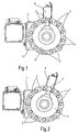
- the embodiment of the tool turret shown in the drawing has a base body 1 in the form of an elongate block on which a tool disk 3 is rotatably mounted about a turret axis 5.
- the tool disk 3 distributed on its circumference twelve tool stations 7, of which in Fig. 1 and 2 only a few are numbered and of which in the representation of Fig. 1 and 2 only one tool station 7 is equipped with a tool holder 9.
- This tool holder 9 is for a in Fig. 1 and 2 not shown rotary tool provided.
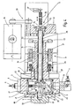
- Fig. 3 and 4 are two tool stations 7 each equipped with a tool holder 9, in each of which a rotary tool is received in the form of a drill 11.
- Fig. 1 the tool holder 9 is shown in an initial working position while Fig. 2 the tool holder 9 is shown in a contrast rotated by about 15 degrees clockwise position.
- Fig. 3 and 4 explained in more detail, is located in the tool holder 9 rotary tool both in the initial working position of Fig. 1 as well as in any, contrary twisted working positions drivable.
- Fig. 3 and 4 show that the tool disk 3 is connected via a screw, of which only one screw 13, with a rotatably mounted in the base body 1 hollow shaft 15, which is shown in the drawing shortened and forms the pivot drive shaft for the tool disk 3.
- This drive takes place as gearless direct drive by means of a torque motor 17, the rotor 19 is arranged directly on the hollow shaft 15 within the associated housing-fixed stator 21.
- the tool disk 3 can be adjusted to precisely defined rotational positions.
- the concentric with the turret 5 hollow shaft 15 surrounds the outside of another concentric hollow shaft 29 which is provided as a drive shaft for the tool drive, which is located within the tool disk 3.
- this hollow shaft 29 at the end remote from the tool disc 3 end a pinion 31 which is connected via a combined toothed belt gear 33 with a drive motor 35 in gear connection.
- the in the tool disk 3 located other end of the hollow shaft 29 carries a ring gear 37 which forms the drive side of a gear head 39 which is provided within the tool disk 3 as a tool drive.
- the gear head 39 has a gear housing 41, which is rotatably supported in the tool disk 3 by means of rolling bearings 43.
- the output side of the gear assembly of the gear head 39 has a driver 45 which is movable by hydraulic actuation in the direction of a double arrow 47 to make the clutch engagement with a tool-side coupling part and thus to establish the drive connection to the drill 11, which is located in the respective tool holder 9 ,
- the drive of the driver 45 via a meshing with the ring gear 37 pinion 49, the rotational position to ensure the engagement of the driver 45 is queried by a sensor 51.
- a switching shaft 53 is provided which is axially displaceable in both directions and in a first and a second clutch switching position by hydraulic actuation of a hydraulic piston 55, wherein the switching positions by position sensors 57th be queried.
- the switching shaft 53 forms the main component of a clutch which is adjustable by the axial displacement of the switching shaft 53 to two switching positions, namely a in Fig. 3 shown first switching position in which the switching shaft 53 is advanced in the direction of the tool disk 3, that is shifted in the figures to the left, and a second switching position, the in Fig. 4 is shown, wherein the switching shaft 53 is moved backwards, that is to the right in the figures.
- the switching shaft 53 which extends beyond the crown gear 37 of the hollow shaft 29 through the gear head 39 through into an end-side end portion 59 of the tool disk 3, has two at a small distance adjacent Coupling teeth 61 and 63, for their engagement in the end portion 59 of the tool disk 3 and the adjacent housing part 65 of the gear head 39 tooth seats 67 and 69 are formed.
- This Einstattkupplung 71 has a radially projecting coupling tooth 73 which comes into positive engagement with a housing-fixed tooth seat 75 when the gear head 39 and thus the switching shaft 53 is taken in the initial working position by the rotational movement of the tool disk 3.
- the rotational position of the gear head 39 is therefore fixed relative to the main body in the second switching position in which the gear head 39 is decoupled from the tool disk 3.
- the tool disk 3 can be pivoted independently of the tool drive for any purpose, while the possibility exists to operate a rotary tool located at the tool station, which is aligned with the home working position.
- the movement of the switching shaft 53 can take place in the position of the second switching position only when the coupling tooth 73 in the tooth seat 75, it is ensured that the gear head 39 is taken in the initial working position of the tool disk 3, if he from the latter is decoupled.
Landscapes
- Engineering & Computer Science (AREA)
- Mechanical Engineering (AREA)
- Cutting Tools, Boring Holders, And Turrets (AREA)
- Eye Examination Apparatus (AREA)
- Orthopedics, Nursing, And Contraception (AREA)
Claims (7)
- Tourelle d'outil, comprenant un corps (1) de base mis ou à mettre sur une machine-outil et définissant un axe (5) de tourelle autour duquel un plateau (3) d'outil est monté tournant sur le corps (1) de base, plateau qui a plusieurs postes (7) d'outils qui sont répartis sur son pourtour et qui, par rotation du plateau (3) d'outil, peuvent être mis respectivement dans au moins une position de travail, dans laquelle un entraînement d'outil se trouvant à l'intérieur du plateau (3) d'outil vient en prise d'accouplement, par sa partie (45) d'accouplement du côté entraînement, avec une partie d'accouplement du côté outil, pour l'entraînement d'un outil (11), qui se trouve au poste (7) d'outil orienté sur la position de travail, l'entraînement d'outil ayant une tête de réduction montée tournante dans le plateau (3) d'outil, un embrayage (53, 61, 63, 67, 69, 71) se trouvant entre le plateau (3) d'outil et la tête (39) de réduction et pouvant passer entre une première position, dans laquelle la tête (39) de réducteur et le plateau (3) d'outil sont solidaires en rotation l'un de l'autre, et une deuxième position dans laquelle la tête (39) de réduction est découplée du plateau (3) d'outil et est solidaire en rotation du corps (1) de base, l'embrayage comprenant un embrayage à denture, ayant des dents (61, 63) d'accouplement qui, dans la première position du plateau (3) d'outil, sont assemblées à complémentarité de forme avec une partie (65) de carter de la tête (39) de réducteur, et dans laquelle l'embrayage (53, 61, 63, 67, 69, 71) peut être actionné par un arbre (53) de commande, qui peut coulisser axialement, concentriquement à l'axe (9) de la tourelle dans le corps (1) de base et axialement dans le plateau (3) d'outil, entre les positions correspondant à la première position et à la deuxième position, caractérisée en ce que les dents (61, 63) d'accouplement prévues pour l'accouplement et le désaccouplement de la tête (39) de réducteur et du plateau (3) d'outil sont disposées sur la partie avant d'extrémité de l'arbre (53) de commande, passant à travers le carter (41) de la tête (39) de réduction, et peuvent être mises, pour des positions axiales correspondantes de l'axe (53) de commande, en prise et hors de prise avec des sièges (67, 69) de dents associés à la partie (59) avant d'extrémité du plateau (3) d'outil et à la partie (65) avant voisine du carter de la tête (39) de réducteur.
- Tourelle d'outil suivant la revendication 1, caractérisé en ce que l'arbre (53) de commande comporte, dans une partie se trouvant à l'intérieur du corps (1) de base, comme partie constituante de l'embrayage (53, 61, 63, 67, 69, 71), une dent (73) d'accouplement qui est en saillie radialement, qui forme un embrayage (71) à une seule dent, qui, dans la deuxième position, vient en prise par complémentarité de forme avec un siège (75) de dents du corps (1) de base et qui forme la liaison de solidarité en rotation entre la tête (39) de réducteur et le corps (1) de base.
- Tourelle d'outil suivant la revendication 2, caractérisée en ce que la dent (73) d'accouplement de l'embrayage (71) à une seule dent, vient en prise avec le siège (75) de dent du corps (1) de base, dans une position de la tête (39) de réduction correspondant à une position de travail-sortie.
- Tourelle d'outil suivant l'une des revendications 1 à 3, caractérisée en ce que l'arbre (53) de commande est entouré d'un premier arbre (29) creux, monté dans le corps (1) de base et prévu comme arbre entraînement de la tête (39) de réducteur, pour l'entraînement d'outil et d'un deuxième arbre (15) creux, monté au-dessus dans le corps (1) de base et relié en tant qu'arbre d'entraînement en pivotement au plateau (3) d'outil.
- Tourelle d'outil suivant la revendication 4, caractérisée en ce que le premier arbre (29) creux est en prise avec un pignon (49) de l'entraînement d'outil par une couronne (37) se trouvant dans la tête (39) de réducteur.
- Tourelle d'outil suivant la revendication 4 ou 5, caractérisée en ce qu'un moteur (17) de couple, pour un entraînement direct du mouvement de pivotement du plateau (3) d'outil, est monté sur le deuxième arbre (15) creux du rotor (19).
- Tourelle d'outil suivant l'une des revendications 4 à 6, caractérisée en ce qu'un frein (25) à disques multiples est présent entre le corps (1) de base et le deuxième arbre (15) creux pour fixer la position de pivotement du plateau (3) d'outil.
Applications Claiming Priority (2)
| Application Number | Priority Date | Filing Date | Title |
|---|---|---|---|
| DE102007043775A DE102007043775A1 (de) | 2007-09-13 | 2007-09-13 | Werkzeugrevolver |
| PCT/EP2008/006746 WO2009036850A1 (fr) | 2007-09-13 | 2008-08-16 | Tourelle revolver |
Publications (2)
| Publication Number | Publication Date |
|---|---|
| EP2185318A1 EP2185318A1 (fr) | 2010-05-19 |
| EP2185318B1 true EP2185318B1 (fr) | 2011-03-16 |
Family
ID=39876210
Family Applications (1)
| Application Number | Title | Priority Date | Filing Date |
|---|---|---|---|
| EP08785588A Not-in-force EP2185318B1 (fr) | 2007-09-13 | 2008-08-16 | Tourelle revolver |
Country Status (4)
| Country | Link |
|---|---|
| EP (1) | EP2185318B1 (fr) |
| AT (1) | ATE501811T1 (fr) |
| DE (2) | DE102007043775A1 (fr) |
| WO (1) | WO2009036850A1 (fr) |
Cited By (2)
| Publication number | Priority date | Publication date | Assignee | Title |
|---|---|---|---|---|
| DE102010021949A1 (de) * | 2010-05-28 | 2011-12-01 | Sauter Feinmechanik Gmbh | Werkzeugrevolver |
| US9233446B2 (en) | 2010-05-28 | 2016-01-12 | Sauter Feinmechanik Gmbh | Tool turret |
Families Citing this family (2)
| Publication number | Priority date | Publication date | Assignee | Title |
|---|---|---|---|---|
| CN108031878A (zh) * | 2017-12-18 | 2018-05-15 | 山东鲁南机床有限公司 | 星型动力刀架结构变换设计方案 |
| CN113941718A (zh) * | 2020-07-17 | 2022-01-18 | 裕纮科技有限公司 | 动力刀塔装置 |
Family Cites Families (8)
| Publication number | Priority date | Publication date | Assignee | Title |
|---|---|---|---|---|
| IT1215998B (it) | 1988-03-04 | 1990-02-22 | Duplomatic | Torretta portautensili a revolver,per torni, centri di lavorazione a tornire e simili. |
| DE3930121C1 (en) * | 1989-09-09 | 1991-01-17 | Sauter Feinmechanik Gmbh, 7430 Metzingen, De | Turret turntable holding tools - incorporates hydraulic cylinder operating mechanical clamp |
| DE4125003A1 (de) * | 1991-07-27 | 1993-01-28 | Index Werke Kg Hahn & Tessky | Werkzeugrevolver, insbesondere drehmaschinen |
| DE4135735C1 (fr) * | 1991-10-30 | 1992-10-15 | Sauter Feinmechanik Gmbh, 7430 Metzingen, De | |
| DE19516985A1 (de) * | 1995-05-09 | 1996-11-14 | Sauter Kg Feinmechanik | Werkzeugrevolver |
| DE19838505A1 (de) * | 1998-08-25 | 2000-03-02 | Index Werke Kg Hahn & Tessky | Werkzeugrevolvereinrichtung für eine CNC-gesteuerte Drehmaschine |
| JP2003071615A (ja) * | 2001-08-30 | 2003-03-12 | Mori Seiki Co Ltd | タレット刃物台 |
| DE102005033890A1 (de) | 2005-07-20 | 2007-01-25 | Sauter Feinmechanik Gmbh | Werkzeugrevolver |
-
2007
- 2007-09-13 DE DE102007043775A patent/DE102007043775A1/de not_active Withdrawn
-
2008
- 2008-08-16 EP EP08785588A patent/EP2185318B1/fr not_active Not-in-force
- 2008-08-16 DE DE502008002900T patent/DE502008002900D1/de active Active
- 2008-08-16 AT AT08785588T patent/ATE501811T1/de active
- 2008-08-16 WO PCT/EP2008/006746 patent/WO2009036850A1/fr active Application Filing
Cited By (3)
| Publication number | Priority date | Publication date | Assignee | Title |
|---|---|---|---|---|
| DE102010021949A1 (de) * | 2010-05-28 | 2011-12-01 | Sauter Feinmechanik Gmbh | Werkzeugrevolver |
| US9233446B2 (en) | 2010-05-28 | 2016-01-12 | Sauter Feinmechanik Gmbh | Tool turret |
| US9358652B2 (en) | 2010-05-28 | 2016-06-07 | Sauter Feinmechanik Gmbh | Tool turret |
Also Published As
| Publication number | Publication date |
|---|---|
| ATE501811T1 (de) | 2011-04-15 |
| EP2185318A1 (fr) | 2010-05-19 |
| WO2009036850A1 (fr) | 2009-03-26 |
| DE102007043775A1 (de) | 2009-03-19 |
| DE502008002900D1 (de) | 2011-04-28 |
Similar Documents
| Publication | Publication Date | Title |
|---|---|---|
| DE60201794T2 (de) | Revolverwerkzeughalter | |
| EP2170553B1 (fr) | Unité de tourelle porte-outils pour une machine-outil | |
| EP2480372B1 (fr) | Dispositif d'entraînement | |
| EP2576134B1 (fr) | Tourelle revolver | |
| EP2517811A1 (fr) | Dispositif de forage | |
| EP2185318B1 (fr) | Tourelle revolver | |
| WO2019042907A1 (fr) | Machine-outil portative | |
| EP1600225B1 (fr) | Machine à poinçonner avec entraînement de rotation et de levage électrique | |
| EP2158998B1 (fr) | Tourelle revolver | |
| DE4201849C1 (fr) | ||
| EP0396876B1 (fr) | Poinçonneuse à révolver avec outil rotatif | |
| DE19627457A1 (de) | Einrichtung zum spielfreien Antreiben eines Drehtisches o. dgl. um eine Drehachse, insbesondere für eine Verzahnmaschine | |
| DE4235095C2 (de) | Werkzeugrevolver | |
| DE20218643U1 (de) | Getriebemechanismus für Bohr/Fräs-Werkzeuge | |
| DE102010021949A1 (de) | Werkzeugrevolver | |
| DE102016221297A1 (de) | Schaltbares Planetengetriebe | |
| EP1128930A1 (fr) | Tete d'outil a logement de broche | |
| EP3381605B1 (fr) | Tour multibroche | |
| EP1163976A1 (fr) | Entrainement avec une transmission variable pour un dispositif porte outil | |
| DE4236686C1 (de) | Fräseinrichtung mit einem Werkzeughalter für einen Werkzeugträger einer Drehmaschine | |
| EP0539667B1 (fr) | Tourelle porte-outil | |
| DE3930787C2 (fr) | ||
| DE4005181C1 (en) | Machine tool work spindle drive - has angularly adjustable motor with spur gearing controlled via pawl | |
| EP3072632B1 (fr) | Tourelle revolver | |
| DE3806769A1 (de) | Revolverkopf mit angetriebenem werkzeug |
Legal Events
| Date | Code | Title | Description |
|---|---|---|---|
| PUAI | Public reference made under article 153(3) epc to a published international application that has entered the european phase |
Free format text: ORIGINAL CODE: 0009012 |
|
| 17P | Request for examination filed |
Effective date: 20091217 |
|
| AK | Designated contracting states |
Kind code of ref document: A1 Designated state(s): AT BE BG CH CY CZ DE DK EE ES FI FR GB GR HR HU IE IS IT LI LT LU LV MC MT NL NO PL PT RO SE SI SK TR |
|
| AX | Request for extension of the european patent |
Extension state: AL BA MK RS |
|
| GRAP | Despatch of communication of intention to grant a patent |
Free format text: ORIGINAL CODE: EPIDOSNIGR1 |
|
| DAX | Request for extension of the european patent (deleted) | ||
| GRAS | Grant fee paid |
Free format text: ORIGINAL CODE: EPIDOSNIGR3 |
|
| GRAA | (expected) grant |
Free format text: ORIGINAL CODE: 0009210 |
|
| AK | Designated contracting states |
Kind code of ref document: B1 Designated state(s): AT BE BG CH CY CZ DE DK EE ES FI FR GB GR HR HU IE IS IT LI LT LU LV MC MT NL NO PL PT RO SE SI SK TR |
|
| REG | Reference to a national code |
Ref country code: GB Ref legal event code: FG4D Free format text: NOT ENGLISH |
|
| REG | Reference to a national code |
Ref country code: CH Ref legal event code: EP |
|
| REG | Reference to a national code |
Ref country code: IE Ref legal event code: FG4D |
|
| REF | Corresponds to: |
Ref document number: 502008002900 Country of ref document: DE Date of ref document: 20110428 Kind code of ref document: P |
|
| REG | Reference to a national code |
Ref country code: DE Ref legal event code: R096 Ref document number: 502008002900 Country of ref document: DE Effective date: 20110428 |
|
| REG | Reference to a national code |
Ref country code: NL Ref legal event code: VDEP Effective date: 20110316 |
|
| PG25 | Lapsed in a contracting state [announced via postgrant information from national office to epo] |
Ref country code: LV Free format text: LAPSE BECAUSE OF FAILURE TO SUBMIT A TRANSLATION OF THE DESCRIPTION OR TO PAY THE FEE WITHIN THE PRESCRIBED TIME-LIMIT Effective date: 20110316 Ref country code: HR Free format text: LAPSE BECAUSE OF FAILURE TO SUBMIT A TRANSLATION OF THE DESCRIPTION OR TO PAY THE FEE WITHIN THE PRESCRIBED TIME-LIMIT Effective date: 20110316 Ref country code: ES Free format text: LAPSE BECAUSE OF FAILURE TO SUBMIT A TRANSLATION OF THE DESCRIPTION OR TO PAY THE FEE WITHIN THE PRESCRIBED TIME-LIMIT Effective date: 20110627 Ref country code: NO Free format text: LAPSE BECAUSE OF FAILURE TO SUBMIT A TRANSLATION OF THE DESCRIPTION OR TO PAY THE FEE WITHIN THE PRESCRIBED TIME-LIMIT Effective date: 20110616 Ref country code: LT Free format text: LAPSE BECAUSE OF FAILURE TO SUBMIT A TRANSLATION OF THE DESCRIPTION OR TO PAY THE FEE WITHIN THE PRESCRIBED TIME-LIMIT Effective date: 20110316 Ref country code: SE Free format text: LAPSE BECAUSE OF FAILURE TO SUBMIT A TRANSLATION OF THE DESCRIPTION OR TO PAY THE FEE WITHIN THE PRESCRIBED TIME-LIMIT Effective date: 20110316 Ref country code: GR Free format text: LAPSE BECAUSE OF FAILURE TO SUBMIT A TRANSLATION OF THE DESCRIPTION OR TO PAY THE FEE WITHIN THE PRESCRIBED TIME-LIMIT Effective date: 20110617 |
|
| LTIE | Lt: invalidation of european patent or patent extension |
Effective date: 20110316 |
|
| PG25 | Lapsed in a contracting state [announced via postgrant information from national office to epo] |
Ref country code: CY Free format text: LAPSE BECAUSE OF FAILURE TO SUBMIT A TRANSLATION OF THE DESCRIPTION OR TO PAY THE FEE WITHIN THE PRESCRIBED TIME-LIMIT Effective date: 20110316 Ref country code: BG Free format text: LAPSE BECAUSE OF FAILURE TO SUBMIT A TRANSLATION OF THE DESCRIPTION OR TO PAY THE FEE WITHIN THE PRESCRIBED TIME-LIMIT Effective date: 20110616 Ref country code: FI Free format text: LAPSE BECAUSE OF FAILURE TO SUBMIT A TRANSLATION OF THE DESCRIPTION OR TO PAY THE FEE WITHIN THE PRESCRIBED TIME-LIMIT Effective date: 20110316 Ref country code: SI Free format text: LAPSE BECAUSE OF FAILURE TO SUBMIT A TRANSLATION OF THE DESCRIPTION OR TO PAY THE FEE WITHIN THE PRESCRIBED TIME-LIMIT Effective date: 20110316 |
|
| REG | Reference to a national code |
Ref country code: IE Ref legal event code: FD4D |
|
| PG25 | Lapsed in a contracting state [announced via postgrant information from national office to epo] |
Ref country code: PT Free format text: LAPSE BECAUSE OF FAILURE TO SUBMIT A TRANSLATION OF THE DESCRIPTION OR TO PAY THE FEE WITHIN THE PRESCRIBED TIME-LIMIT Effective date: 20110718 Ref country code: IE Free format text: LAPSE BECAUSE OF FAILURE TO SUBMIT A TRANSLATION OF THE DESCRIPTION OR TO PAY THE FEE WITHIN THE PRESCRIBED TIME-LIMIT Effective date: 20110316 Ref country code: EE Free format text: LAPSE BECAUSE OF FAILURE TO SUBMIT A TRANSLATION OF THE DESCRIPTION OR TO PAY THE FEE WITHIN THE PRESCRIBED TIME-LIMIT Effective date: 20110316 |
|
| PG25 | Lapsed in a contracting state [announced via postgrant information from national office to epo] |
Ref country code: IS Free format text: LAPSE BECAUSE OF FAILURE TO SUBMIT A TRANSLATION OF THE DESCRIPTION OR TO PAY THE FEE WITHIN THE PRESCRIBED TIME-LIMIT Effective date: 20110716 Ref country code: RO Free format text: LAPSE BECAUSE OF FAILURE TO SUBMIT A TRANSLATION OF THE DESCRIPTION OR TO PAY THE FEE WITHIN THE PRESCRIBED TIME-LIMIT Effective date: 20110316 Ref country code: CZ Free format text: LAPSE BECAUSE OF FAILURE TO SUBMIT A TRANSLATION OF THE DESCRIPTION OR TO PAY THE FEE WITHIN THE PRESCRIBED TIME-LIMIT Effective date: 20110316 Ref country code: SK Free format text: LAPSE BECAUSE OF FAILURE TO SUBMIT A TRANSLATION OF THE DESCRIPTION OR TO PAY THE FEE WITHIN THE PRESCRIBED TIME-LIMIT Effective date: 20110316 |
|
| PG25 | Lapsed in a contracting state [announced via postgrant information from national office to epo] |
Ref country code: MT Free format text: LAPSE BECAUSE OF FAILURE TO SUBMIT A TRANSLATION OF THE DESCRIPTION OR TO PAY THE FEE WITHIN THE PRESCRIBED TIME-LIMIT Effective date: 20110316 Ref country code: NL Free format text: LAPSE BECAUSE OF FAILURE TO SUBMIT A TRANSLATION OF THE DESCRIPTION OR TO PAY THE FEE WITHIN THE PRESCRIBED TIME-LIMIT Effective date: 20110316 |
|
| PLBE | No opposition filed within time limit |
Free format text: ORIGINAL CODE: 0009261 |
|
| STAA | Information on the status of an ep patent application or granted ep patent |
Free format text: STATUS: NO OPPOSITION FILED WITHIN TIME LIMIT |
|
| 26N | No opposition filed |
Effective date: 20111219 |
|
| BERE | Be: lapsed |
Owner name: SAUTER FEINMECHANIK G.M.B.H. Effective date: 20110831 |
|
| PG25 | Lapsed in a contracting state [announced via postgrant information from national office to epo] |
Ref country code: PL Free format text: LAPSE BECAUSE OF FAILURE TO SUBMIT A TRANSLATION OF THE DESCRIPTION OR TO PAY THE FEE WITHIN THE PRESCRIBED TIME-LIMIT Effective date: 20110316 Ref country code: DK Free format text: LAPSE BECAUSE OF FAILURE TO SUBMIT A TRANSLATION OF THE DESCRIPTION OR TO PAY THE FEE WITHIN THE PRESCRIBED TIME-LIMIT Effective date: 20110316 |
|
| PG25 | Lapsed in a contracting state [announced via postgrant information from national office to epo] |
Ref country code: MC Free format text: LAPSE BECAUSE OF NON-PAYMENT OF DUE FEES Effective date: 20110831 |
|
| REG | Reference to a national code |
Ref country code: DE Ref legal event code: R097 Ref document number: 502008002900 Country of ref document: DE Effective date: 20111219 |
|
| REG | Reference to a national code |
Ref country code: FR Ref legal event code: ST Effective date: 20120430 |
|
| PG25 | Lapsed in a contracting state [announced via postgrant information from national office to epo] |
Ref country code: BE Free format text: LAPSE BECAUSE OF NON-PAYMENT OF DUE FEES Effective date: 20110831 |
|
| PG25 | Lapsed in a contracting state [announced via postgrant information from national office to epo] |
Ref country code: FR Free format text: LAPSE BECAUSE OF NON-PAYMENT OF DUE FEES Effective date: 20110831 |
|
| REG | Reference to a national code |
Ref country code: CH Ref legal event code: PL |
|
| GBPC | Gb: european patent ceased through non-payment of renewal fee |
Effective date: 20120816 |
|
| PG25 | Lapsed in a contracting state [announced via postgrant information from national office to epo] |
Ref country code: LI Free format text: LAPSE BECAUSE OF NON-PAYMENT OF DUE FEES Effective date: 20120831 Ref country code: CH Free format text: LAPSE BECAUSE OF NON-PAYMENT OF DUE FEES Effective date: 20120831 |
|
| PG25 | Lapsed in a contracting state [announced via postgrant information from national office to epo] |
Ref country code: LU Free format text: LAPSE BECAUSE OF NON-PAYMENT OF DUE FEES Effective date: 20110816 |
|
| PG25 | Lapsed in a contracting state [announced via postgrant information from national office to epo] |
Ref country code: GB Free format text: LAPSE BECAUSE OF NON-PAYMENT OF DUE FEES Effective date: 20120816 |
|
| PG25 | Lapsed in a contracting state [announced via postgrant information from national office to epo] |
Ref country code: TR Free format text: LAPSE BECAUSE OF FAILURE TO SUBMIT A TRANSLATION OF THE DESCRIPTION OR TO PAY THE FEE WITHIN THE PRESCRIBED TIME-LIMIT Effective date: 20110316 |
|
| PG25 | Lapsed in a contracting state [announced via postgrant information from national office to epo] |
Ref country code: HU Free format text: LAPSE BECAUSE OF FAILURE TO SUBMIT A TRANSLATION OF THE DESCRIPTION OR TO PAY THE FEE WITHIN THE PRESCRIBED TIME-LIMIT Effective date: 20110316 |
|
| REG | Reference to a national code |
Ref country code: AT Ref legal event code: MM01 Ref document number: 501811 Country of ref document: AT Kind code of ref document: T Effective date: 20130816 |
|
| PG25 | Lapsed in a contracting state [announced via postgrant information from national office to epo] |
Ref country code: AT Free format text: LAPSE BECAUSE OF NON-PAYMENT OF DUE FEES Effective date: 20130816 |
|
| PGFP | Annual fee paid to national office [announced via postgrant information from national office to epo] |
Ref country code: DE Payment date: 20180831 Year of fee payment: 11 Ref country code: IT Payment date: 20180719 Year of fee payment: 11 |
|
| REG | Reference to a national code |
Ref country code: DE Ref legal event code: R119 Ref document number: 502008002900 Country of ref document: DE |
|
| PG25 | Lapsed in a contracting state [announced via postgrant information from national office to epo] |
Ref country code: DE Free format text: LAPSE BECAUSE OF NON-PAYMENT OF DUE FEES Effective date: 20200303 |
|
| PG25 | Lapsed in a contracting state [announced via postgrant information from national office to epo] |
Ref country code: IT Free format text: LAPSE BECAUSE OF NON-PAYMENT OF DUE FEES Effective date: 20190816 |