EP2184831A2 - Rechargeable electric power tool - Google Patents
Rechargeable electric power tool Download PDFInfo
- Publication number
- EP2184831A2 EP2184831A2 EP09014081A EP09014081A EP2184831A2 EP 2184831 A2 EP2184831 A2 EP 2184831A2 EP 09014081 A EP09014081 A EP 09014081A EP 09014081 A EP09014081 A EP 09014081A EP 2184831 A2 EP2184831 A2 EP 2184831A2
- Authority
- EP
- European Patent Office
- Prior art keywords
- temperature
- threshold value
- determined
- motor
- operation mode
- Prior art date
- Legal status (The legal status is an assumption and is not a legal conclusion. Google has not performed a legal analysis and makes no representation as to the accuracy of the status listed.)
- Withdrawn
Links
Images


Classifications
-
- B—PERFORMING OPERATIONS; TRANSPORTING
- B25—HAND TOOLS; PORTABLE POWER-DRIVEN TOOLS; MANIPULATORS
- B25F—COMBINATION OR MULTI-PURPOSE TOOLS NOT OTHERWISE PROVIDED FOR; DETAILS OR COMPONENTS OF PORTABLE POWER-DRIVEN TOOLS NOT PARTICULARLY RELATED TO THE OPERATIONS PERFORMED AND NOT OTHERWISE PROVIDED FOR
- B25F5/00—Details or components of portable power-driven tools not particularly related to the operations performed and not otherwise provided for
- B25F5/008—Cooling means
-
- H—ELECTRICITY
- H02—GENERATION; CONVERSION OR DISTRIBUTION OF ELECTRIC POWER
- H02J—ELECTRIC POWER NETWORKS; CIRCUIT ARRANGEMENTS OR SYSTEMS FOR SUPPLYING OR DISTRIBUTING ELECTRIC POWER; SYSTEMS FOR STORING ELECTRIC ENERGY
- H02J7/00—Circuit arrangements for charging or discharging batteries or for supplying loads from batteries
- H02J7/855—Circuit arrangements for charging or discharging batteries or for supplying loads from batteries with circuits adapted for supplying loads from the battery
-
- H—ELECTRICITY
- H02—GENERATION; CONVERSION OR DISTRIBUTION OF ELECTRIC POWER
- H02J—ELECTRIC POWER NETWORKS; CIRCUIT ARRANGEMENTS OR SYSTEMS FOR SUPPLYING OR DISTRIBUTING ELECTRIC POWER; SYSTEMS FOR STORING ELECTRIC ENERGY
- H02J7/00—Circuit arrangements for charging or discharging batteries or for supplying loads from batteries
- H02J7/90—Regulation of charging or discharging current or voltage
- H02J7/971—Regulation of charging or discharging current or voltage the charge cycle being controlled or terminated in response to non-electric parameters
- H02J7/975—Regulation of charging or discharging current or voltage the charge cycle being controlled or terminated in response to non-electric parameters in response to temperature
Definitions
- the present invention relates to a rechargeable electric power tool.
- a rechargeable electric power tool used as an electric driver or the like, which includes a motor driven by the electric power supplied from a rechargeable battery pack, a field effect transistor (FET) serving as a switching element for regulating power distribution to the motor and a microcomputer for controlling rotation of the motor through the FET.
- FET field effect transistor
- the motor is rotationally driven at the maximum output power by switching on the FET and is stopped by switching off the FET.
- the revolution number of the motor is controlled by driving the FET through pulse width modulation (PWM).
- an electric power tool of the type in which a temperature sensor is arranged in the battery cell of a battery pack.
- the temperature of the battery cell is detected by a temperature detecting circuit connected to the temperature sensor. If the temperature thus detected is high, a microcomputer restricts rotation of the motor or forcibly stops the motor in order to prevent thermal degradation of the battery cell (see, e.g., Japanese Patent Laid-open Publication No. 2007-222991 ).
- an inner coil type motor namely, a motor having a rotor wound with a coil
- a motor having a rotor wound with a coil is often used in a rechargeable electric power tool.
- the temperature of the rotor of the motor is directly detected by a rotor temperature detection unit instead of detecting the temperature of a battery pack, in which case a microcomputer restricts rotation of the motor based on the temperature thus detected. Since the rotor is a rotating body, however, it is almost impossible to detect the temperature of the rotor. Due to the large heat capacity of a motor case, it is sometimes the case that smoke generation occurs in the motor case before the temperature of the rotor grows high.
- the present invention provides a rechargeable electric power tool capable of preventing a motor from falling into an overload state.
- a rechargeable electric power tool including a motor driven by a secondary battery as a power source, a switching element for regulating power supplied to the motor, a motor control unit for controlling rotation of the motor through the switching element, a lead wire for supplying a drive current to the motor therethrough and a trigger switch changed over by a user for turning on or off the drive current supplied to the motor through the lead wire, wherein a first temperature detection unit is arranged on the lead wire and a first temperature threshold value T th1 , a second temperature threshold value T th2 lower than the T th1 , a first preset temperature increase rate ( ⁇ T/ ⁇ t) s1 and a third temperature threshold value T th3 lower than the T th2 are set for the first temperature detection unit, wherein, based on a temperature detection signal outputted from the first temperature detection unit, the motor control unit calculates a first calculated temperature increase rate ( ⁇ T/ ⁇ t) by dividing a temperature elevation degree ⁇ T by
- the configuration noted above has the following advantageous effect.
- the motor control unit decides that the motor may fall into an overload state.
- the motor control unit is set in the limited operation mode in which the motor control unit stops rotation of the motor or in which the revolution number of the motor is limited to a predetermined value or less.
- the motor is stopped or otherwise limited in its rotation before it actually falls into an overload state. This assists in preventing occurrence of trouble such as smoke generation or the like in the motor.
- the first temperature detection unit is arranged on the lead wire through which to supply an electric current to the coil of the motor. This assures enhanced heat transfer from the coil as a heat source to the first temperature detection unit and makes it possible to detect the temperature of the coil with increased temperature-following capability.
- the determination criteria for setting the motor control unit in the limited operation mode include not only the determination that the detected temperature T 1 is greater than the first temperature threshold value T th1 but also the magnitude relation between the first calculated temperature increase rate ( ⁇ T/ ⁇ t) and the first preset temperature increase rate ( ⁇ T/ ⁇ t) s1 after the detected temperature T 1 has been determined to be greater than the second temperature threshold value T th2 .
- the motor control unit is set in the limited operation mode not only when the detected temperature T 1 exceeds the first temperature threshold value T th1 but also when a sharp increase in the temperature of the coil (or the motor) is detected. This makes it possible to effectively prevent the motor from falling into an overload state.
- the motor control unit returns to the normal operation mode if the detected temperature T 1 is determined to be smaller than the third temperature threshold value T th3 . This eliminates the possibility of impairing the handling property of the rechargeable electric power tool.
- a switch block for accommodating the trigger switch and the first temperature detection unit may be arranged in a contact point portion between the lead wire and the switch block.
- the motor may include a rotor, a coil, a stator and a motor case for accommodating the rotor, the coil and the stator, wherein a second temperature detection unit in which are set a first temperature threshold value T tha , a second temperature threshold value T thb lower than the first temperature threshold value T tha by a preset temperature difference LT sa, a first preset temperature increase rate ( ⁇ T/ ⁇ t) s2 and a third temperature threshold value T thc lower than the second temperature threshold value T thb by a preset temperature difference ⁇ T sb is arranged in the motor case, wherein, based on a temperature detection signal outputted from the second temperature detection unit, the motor control unit calculates a second calculated temperature increase rate ( ⁇ T/ ⁇ t) by dividing a temperature elevation degree ⁇ T by a lapse time ⁇ t, wherein, upon changeover of the trigger switch, the motor control unit determines the magnitude relation between the detected temperature T 1 corresponding to the
- the configuration noted above has the following advantageous effect.
- the motor control unit decides that the motor may fall into an overload state.
- the motor control unit is set in the limited operation mode in which the motor control unit stops rotation of the motor or in which the revolution number of the motor is limited to a predetermined value or less. Thanks to this feature, the motor is stopped or otherwise limited in its rotation before it actually falls into an overload state. This assists in preventing occurrence of trouble such as smoke generation or the like in the motor.
- the determination criteria for setting the motor control unit in the limited operation mode include not only the determination that the detected temperature T 1 is greater than the first temperature threshold value T th1 and the determination that the detected temperature T 2 is greater than the first temperature threshold value T tha but also the magnitude relation between the first calculated temperature increase rate ( ⁇ T/ ⁇ t) and the first preset temperature increase rate ( ⁇ T/ ⁇ t) s1 after the detected temperature T 1 has been determined to be greater than the second temperature threshold value T th2 and the magnitude relation between the second calculated temperature increase rate ( ⁇ T/ ⁇ t) and the first preset temperature increase rate ( ⁇ T/ ⁇ t) s2 after the detected temperature T 2 has been determined to be greater than the second temperature threshold value T thb .
- the motor control unit is set in the limited operation mode not only when the detected temperature T 1 exceeds the first temperature threshold value T th1 or the detected temperature T 2 exceeds the first temperature threshold value T tha but also when a sharp increase in the temperature of the coil (or the motor) is detected in the temperature range equal to or higher than the second temperature threshold value T th2 or T thb . This makes it possible to effectively prevent the motor from falling into an overload state.
- the motor control unit returns to the normal operation mode if the detected temperature T 1 is determined to be smaller than the third temperature threshold value T th3 or if the detected temperature T 2 is determined to be smaller than the third temperature threshold value T thc . This eliminates the possibility of impairing the handling property of the rechargeable electric power tool.
- fourth temperature threshold values T th4 and T thd respectively higher than the second temperature threshold values T th2 and T thb but lower than the first temperature threshold values T th1 and T tha and second preset temperature increase rates ( ⁇ T/ ⁇ t) s11 nd ( ⁇ T/ ⁇ t) s12 respectively smaller than the first preset temperature increase rates ( ⁇ T/ ⁇ t) s1 nd ( ⁇ T/ ⁇ t) s2 may set in the first temperature detection unit and the second temperature detection unit, wherein, upon changeover of the trigger switch, the motor control unit determines the magnitude relation between the detected temperatures T 1 and T 2 corresponding to the temperature detection signals outputted from the first temperature detection unit and the second temperature detection unit and the fourth temperature threshold values T th4 and T thd , and the magnitude relation between the first and second calculated temperature increase rates ( ⁇ T/ ⁇ t) and the second preset temperature increase rates ( ⁇ T/ ⁇ t) s11 and ( ⁇ T/ ⁇ t) s12, wherein, if the first
- the configuration noted above has the following advantageous effect.
- the motor control unit is set in the limited operation mode.
- the determination criteria for setting the motor control unit in the limited operation mode further include the magnitude relation between the first calculated temperature increase rate ( ⁇ T/ ⁇ t) nd the second preset temperature increase rate ( ⁇ T/ ⁇ t) s11 after the detected temperature T 1 has been determined to be greater than the fourth temperature threshold value T th4 and the magnitude relation between the second calculated temperature increase rate ( ⁇ T/ ⁇ t) and the second preset temperature increase rate ( ⁇ T/ ⁇ t) s12 after the detected temperature T 2 has been determined to be greater than the fourth temperature threshold value T thd .
- the motor control unit is more rapidly set in the limited operation mode when a sharp increase in the temperature of the coil (or the motor) is detected in the temperature range between the fourth temperature threshold value T th4 or T thd and the first temperature threshold value T th1 or T tha than when a sharp increase in the temperature of the coil (or the motor) is detected in the temperature range between the second temperature threshold value T th2 or T thb and the fourth temperature threshold value T th4 or T thd .
- This makes it possible to more effectively prevent the motor from falling into an overload state.
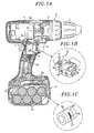
- a rechargeable electric power tool in accordance with the present embodiment is used as an electric driver.
- the power tool includes a rotary output portion 1 for holding a tip driver tool, a motor 4 for driving the rotary output portion 1 through a gear box 3 as a speed reducer, a battery pack 2, i.e., a secondary battery, used as a driving power source for the motor 4, and a trigger switch 5 changed over (turned on or off) by the user's operation of a trigger lever 5a for switching on or off the rotational operation of the motor 4.
- the motor 4 is accommodated within a tool body 6.
- the battery pack 2 is removably mounted to a battery pack mounting portion 6c provided at the lower end of a grip portion 6a of the tool body 6.
- the trigger switch 5 is held within a resin-made switch block 8 provided in the tool body 6.
- Six (a plurality of) battery cells 2a are housed within the battery pack 2 in a serially connected state.
- a circuit board 6b is arranged near the lower end of the grip portion 6a of the tool body 6.
- the motor 4 is a DC motor of well-known configuration in which an electric current is supplied to a coil through a brush and a commutator.
- the motor 4 is provided with a substantially cylindrical motor case 4a for holding therein the brush with a terminal, the commutator, the coil, a rotor and a stator (all of which are not shown in the drawings).
- a lead wire 7 through which an electric current is supplied from the battery pack 2 to the motor 4 via the trigger switch 5.
- the lead wire 7 is electrically connected to a switch block 8 and a contact point portion 7a.
- the trigger switch 5 turns on or off the electric power (or the electric current) supplied to the motor 4 (namely, the coil of the motor 4) through the lead wire 7.
- the lead wire 7 is electrically connected to the coil through the terminal of the brush and the commutator.
- a first thermistor 9 serving as a first temperature detection unit is arranged in the contact point portion 7a shown in Fig. 1A . Since the first thermistor 9 is arranged on the lead wire 7 for supplying an electric current to the coil of the motor 4 therethrough, the heat generated in the coil of the motor 4 is well transferred to the first thermistor 9. This makes it possible to detect the temperature of the motor 4 with enhanced temperature-following capability.
- the first thermistor 9 is an NTC thermistor provided with a thermistor body 9h and an annular terminal 9m.
- the thermistor body 9h is fixed (or screw-fixed) to the contact point portion 7a by virtue of the annular terminal 9m.
- the screw-fixing makes it easy to attach the first thermistor 9 to the contact point portion 7a and keeps the first thermistor 9 in a stably fixed state after its attachment. This makes it possible to reliably detect the temperature while utilizing the advantages, e.g., reduced size, of the NTC thermistor.
- a second thermistor 9a formed of an NTC thermistor and serving as a second temperature detection unit is attached to the motor case 4a by an adhesive tape 9c as shown in Fig. 1A so that it can detect the temperature of the motor case 4a.
- a third thermistor 9b formed of an NTC thermistor and serving as a third temperature detection unit is attached to the battery cell 2a of the battery pack 2 by an adhesive tape 9d as shown in Fig. 1C so that it can detect the temperature of the battery cell 2a of the battery pack 2.
- the rechargeable electric power tool of the present embodiment includes a FET (field effect transistor) 10 as a switching element for regulating power supplied to the motor 4 and a microcomputer 11 as a motor control unit for controlling the rotation of the motor 4 through the FET 10.
- the FET 10 and the microcomputer 11 are arranged in the tool body 6.
- the rechargeable electric power tool further includes the battery pack 2 having six (a plurality of) battery cells 2a serially connected to one another.
- the microcomputer 11 drives the motor 4 to rotate at the greatest output power by switching on the FET 10 and stops the rotation of the motor 4 by switching off the FET 10. Furthermore, the microcomputer 11 controls the revolution number of the motor 4 by driving the FET through pulse width modulation (PWM). In case where the tip driver tool (or the motor 4) needs to be driven with an increased torque, the microcomputer 11 automatically increases the duty ratio of the FET 10 through the use of a well-known control system not shown in Fig. 2 , thereby increasing the electric current supplied to the motor 4 and consequently augmenting the torque.
- PWM pulse width modulation
- the trigger switch 5 includes a first fixed contact point S1 connected to the positive pole of the battery pack 2, a second fixed contact point S2 connected between the output terminal of the motor 4 and the FET 10, and a movable contact point S0 connected to the input terminal of the motor 4. If the trigger switch 5 is turned on by operating the trigger lever 5a, the movable contact point S0 is connected to the first fixed contact point S1. If the trigger switch 5 is turned off, the movable contact point S0 is connected to the second fixed contact point S2.
- a power control unit 12 for controlling the electric power supplied from the battery pack 2 and a voltage regulator circuit (or a regulator) 13 for making the voltage outputted from the battery pack 2 and the power control unit 12 suitable for use in the microcomputer 11.
- the voltage regulator circuit 13 is connected to the movable contact point S0 of the trigger switch 5.
- a temperature detection circuit 14 and an LED display unit 15 as a notification unit are electrically connected to the microcomputer 11.
- the LED display unit 15 is lighted (turned on to emit light) or extinguished in response to the lighting control signal fed from the microcomputer 11.
- the power control unit 12 includes a pnp transistor TR1, an npn transistor TR2 and diodes D1 and D2.
- the transistor TR1 has a emitter terminal connected to the positive pole of the battery pack 2, a base terminal connected to the collector terminal of the transistor TR2, and an collector terminal connected to the voltage regulator circuit 13.
- the transistor TR2 has an emitter terminal kept grounded and a base terminal connected to the microcomputer 11 via the diode D2 and also connected to the movable contact point S0 via the diode D1.
- the battery pack 2 is mounted to the tool body 6 as set forth above. If the trigger lever 5a is operated to turn on the trigger switch 5, the electric power supplied from the battery pack 2 is regulated into a constant voltage of high level (e.g., 5 V) by the voltage regulator circuit 13. The constant voltage of high level is inputted to the microcomputer 11 and also applied to the base terminal of the transistor TR2.
- a constant voltage of high level e.g., 5 V
- an operation control signal is outputted from a lever operation detecting circuit (not shown).
- the lever operation detecting circuit is arranged in the trigger lever 5a to detect the operation amount (or push-in amount) of the latter.
- the operation control signal is inputted to the microcomputer 11 through the voltage regulator circuit 13. Responsive to the operation control signal, the microcomputer 11 applies a voltage of high level to the base terminal of the transistor TR2 via the diode D2.
- the transistor TR2 is switched on and the transistor TR1 is also switched on. Consequently, an electric power is supplied from the battery pack 2 to the microcomputer 11 via the transistor TR1 and the voltage regulator circuit 13, thereby bringing the microcomputer 11 into a power-on state.
- the transistor TR2 since the microcomputer 11 is applying a voltage of high level to the base terminal of the transistor TR2 via the diode D2, the transistor TR2 remains switched on unless the microcomputer 11 applies a voltage of low level (e.g., 0 V) thereto. In other words, the transistor TR2 and the transistor TR1 are switched off if a voltage of low level is applied from the microcomputer 11 to the transistor TR2. This stops the power supply from the battery pack 2 to the microcomputer 11 via the transistor TR1, thereby cutting off the power of the microcomputer 11.
- a voltage of low level e.g., 0 V
- the voltage regulator circuit 13 continues to supply a voltage (5 V) to the microcomputer 11 via the transistor TR1 even if the trigger lever 5a is operated to turn off the trigger switch 5.
- the first thermistor 9 (see Fig. 1 ) arranged in the contact point portion 7a between the lead wire 7 and the switch block 8 is connected to the microcomputer 11 via the temperature detection circuit 14.
- the resistance value of the first thermistor 9 varying with the temperature thereof is converted to a voltage signal as a temperature detection signal which in turn is inputted to the microcomputer 11.
- the voltage signal is then subjected to a specified A/D conversion process in the microcomputer 11 and is converted to a detected temperature T1 (deg) of the lead wire 7 in the contact point portion 7a.
- the second thermistor 9a arranged in the motor case 4a and the third thermistor 9b arranged in the battery cell 2a of the battery pack 2 are electrically connected to the temperature detection circuit 14 (see Fig. 1 ).
- the resistance values of the second and third thermistors 9a and 9b are respectively converted to voltage signals (or temperature detection signals) by the temperature detection circuit 14.
- these voltage signals are respectively converted to a detected temperature T2 (deg) of the motor case 4a and a detected temperature T3 (deg) of the battery cell 2a.
- the FET 10, the microcomputer 11, the power control unit 12, the voltage regulator circuit 13, the temperature detection circuit 14 and the LED display unit 15 are mounted to or formed on the circuit board 6b (see Fig. 1 ) held within the grip portion 6a of the tool body 6.
- the rechargeable electric power tool of the present embodiment is constructed as above.
- a first temperature threshold value T th1 For the first thermistor 9 arranged on the lead wire 7, there are set a first temperature threshold value T th1 , a second temperature threshold value T th2 lower than the first temperature threshold value T th1 by a preset temperature difference ( ⁇ T s1 , a first preset temperature increase rate ( ⁇ T/ ⁇ t) s1 nd a third temperature threshold value T th3 lower than the second temperature threshold value T th2 by a preset temperature difference ( ⁇ T s2 .
- the microcomputer 11 Based on the temperature detection signal outputted from the first thermistor 9, the microcomputer 11 calculates a calculated temperature increase rate ( ⁇ T/ ⁇ t) by dividing a temperature elevation degree ⁇ T y a lapse time ⁇ t. Upon changeover of the trigger switch 5, the microcomputer 11 determines the magnitude relation between the detected temperature T 1 corresponding to the temperature detection signal outputted from the first thermistor 9 and the first temperature threshold value T th1 , the second temperature threshold value T th2 and the third temperature threshold value T th3 , and the magnitude relation between the calculated temperature increase rate ( ⁇ T/ ⁇ t) and the first preset temperature increase rate ( ⁇ T/ ⁇ t) s1 .
- the microcomputer 11 decides that the motor 4 may fall into an overload state and changes the duty ratio of the FET 10 to thereby establish a limited operation mode in which the revolution number of the motor 4 is limited to a predetermined value or less regardless of the pushed amount of the trigger lever 5a.
- the first preset temperature increase rate ( ⁇ T/ ⁇ t) s1 is set equal to or greater than 2 degrees/sec but smaller than 4 degrees/sec.
- the microcomputer 11 determines the magnitude relation between the detected temperature T 1 and the third temperature threshold value T th3 . If the detected temperature T 1 is determined to be smaller than the third temperature threshold value T th3 , the microcomputer 11 releases the limited operation mode and returns to a normal operation mode in which the rotation of the motor 4 is not limited at all and normally controlled depending on the pushed amount of the trigger lever 5a by the FET 10.
- the first temperature threshold value T th1 is set by the microcomputer 11 with respect to the temperature of the contact point portion 7a of the lead wire 7 and is stored in the memory of the microcomputer 11. As shown in Fig. 3 , the motor 4 falls into an overload state when the temperature of coil reaches 100 deg.
- the microcomputer 11 detects the operation of the trigger lever 5a (or the changeover of the trigger switch 5) in response to the operation control signal inputted thereto.
- the present inventors have found the following facts.
- the first thermistor 9 arranged in the contact point portion 7a between the lead wire 7 and the switch block 8 shows higher capability to follow the temperature of the coil as a heat source than the capability exhibited by the second thermistor 9a arranged in the motor case 4a or the third thermistor 9b arranged in the battery pack 2.
- the reason for this appears to be as follows.
- the lead wire 7 or the annular terminal 9m of the contact point portion 7a is small in thermal capacity. Thus, the increase or decrease in the temperature of the lead wire 7 or the annular terminal 9m is easy to occur.
- the first temperature threshold value T th1 is set in view of the knowledge set forth above.
- the third temperature threshold value T th3 is set to ensure that, even when the motor 4 falls into a locked state, the possibility of smoke generation or other trouble in the motor 4 can be completely eliminated insofar as the detected temperature T 1 is kept smaller than the third temperature threshold value T th3 .
- the FET 10 may be turned off (or the duty ratio of the FET 10 may be made zero) to stop the operation of the motor 4, instead of limiting the revolution number of the motor 4 to a predetermined value or less.
- the lever operation detecting circuit inputs an operation control signal to the microcomputer 11 through the voltage regulator circuit 13.
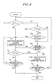
- the microcomputer 11 is supplied with electric power to start its operation if in a power-off state and determines the magnitude relation between the detected temperature T 1 corresponding to the temperature detection signal outputted from the first thermistor 9 and the first temperature threshold value T th1 (step S1).
- the microcomputer 11 is set in the normal operation mode.
- step S1 If the detected temperature T 1 is determined to be greater than the first temperature threshold value T th1 in step S1 (namely, if YES in step S1), the microcomputer 11 decides that the motor 4 may fall into an overload state and the setting of the microcomputer 11 is changed from the normal operation mode to a limited operation mode (step S2) (see Fig. 3 ). Then, the LED display unit 15 is turned on by the microcomputer 11 to notify the user of such a situation. In case where the limited operation mode has already been set, the microcomputer 11 maintains the limited operation mode.
- step S1 If the detected temperature T 1 is determined to be equal to or smaller than the first temperature threshold value T th1 in step S1 (namely, if NO in step S1), the microcomputer 11 determines the magnitude relation between the detected temperature T 1 and the second temperature threshold value T th2 (step S2a).
- step S3a If the detected temperature T 1 is determined to be greater than the second temperature threshold value T th2 in step S2a (namely, if YES in step S2a), the microcomputer 11 determines the magnitude relation between the calculated temperature increase rate ( ⁇ T/ ⁇ t) and the first preset temperature increase rate ( ⁇ T/ ⁇ t) s1 (step S3a).
- step S4a it is determined whether the microcomputer 11 is in limited operation mode. If it is determined to be limited operation mode, the flow proceeds to step S3 where the microcomputer 11 determines the magnitude relation between the detected temperature T 1 (deg) and the third temperature threshold value T th3 (deg) (step S3). If NO in step S4a, the microcomputer 11 maintains the normal operation mode (step 5a).
- step S3a if the calculated temperature increase rate ( ⁇ T/ ⁇ t) is determined to be greater than the first preset temperature increase rate ( ⁇ T/ ⁇ t) s1 n step S3a (namely, if YES in step S3a), the flow proceeds to step S2 in which the setting of the microcomputer 11 is changed from the normal operation mode to the limited operation mode.
- step S4a determines whether the microcomputer 11 is in the limited operation mode. If NO in step S4a, the microcomputer 11 maintains the normal operation mode (step 5a).
- the microcomputer 11 determines the magnitude relation between the detected temperature T 1 (deg) and the third temperature threshold value T th3 (deg) (step S3).
- step S3 As a result of heat dissipation from the coil of the motor 4, if the detected temperature T 1 is determined to be smaller than the third temperature threshold value T th3 in step S3 (namely, if YES in step S3), the setting of the microcomputer 11 is changed (restored) from the limited operation mode to the normal operation mode (see Fig. 3 ) (step S5a). Then, the LED display unit 15 is turned off by the microcomputer 11 to notify the user of such a situation.
- step S3 determines whether the trigger switch 5 is turned off (step S4) and if NO in step S4, the microcomputer 11 maintains the limited operation mode (step S2).
- the microcomputer 11 does not come back to the normal operation mode unless the detected temperature T 1 becomes smaller than the third temperature threshold value T th3 .
- step S6a If the trigger switch 5 is on (step S6a) while the microcomputer 11 is in the normal operation mode, the determination of step S1 is performed again.
- the rechargeable electric power tool of the present embodiment can offer the following advantageous effect.
- the microcomputer 11 decides that the motor 4 may fall into an overload state.
- the microcomputer 11 is set in the limited operation mode in which the revolution number of the motor 4 is limited to a predetermined value or less. Thanks to this feature, the revolution number of the motor 4 is limited to a predetermined value or less before the motor 4 actually falls into an overload state.
- the first thermistor 9 is arranged on the lead wire 7 through which to supply an electric current to the coil of the motor 4. This assures enhanced heat transfer from the coil as a heat source to the first thermistor 9 and makes it possible to detect the temperature of the coil with increased temperature-following capability.
- the determination criteria for setting the microcomputer 11 in the limited operation mode include not only the determination that the detected temperature T 1 is greater than the first temperature threshold value T th1 but also the magnitude relation between the calculated temperature increase rate ( ⁇ T/ ⁇ t) and the first preset temperature increase rate ( ⁇ T/ ⁇ t) s1 after the detected temperature T 1 has been determined to be greater than the second temperature threshold value T th2 when it is not greater than Tth1.
- the microcomputer 11 is set in the limited operation mode not only when the detected temperature T 1 exceeds the first temperature threshold value T th1 but also when a sharp increase in the temperature of the coil (or the motor 4) is detected. This makes it possible to effectively prevent the motor 4 from falling into an overload state.
- the microcomputer 11 returns to the normal operation mode if the trigger lever 5a is operated and if the detected temperature T 1 is determined to be smaller than the third temperature threshold value T th3 . This eliminates the possibility of impairing the handling property of the rechargeable electric power tool.
- the rechargeable electric power tool of the present embodiment is the same in configuration as the power tool of the first embodiment shown in Figs. 1 and 2 . Common parts will be designated by like reference characters and will be omitted from description.
- a first temperature threshold value T tn1 a second temperature threshold value T th2 lower than the first temperature threshold value T th1 by a preset temperature difference ⁇ T s1 , a first preset temperature increase rate ( ⁇ T/ ⁇ t) s1 and a third temperature threshold value T th3 lower than the second temperature threshold value T th2 by a preset temperature difference ⁇ T s2 are set in the first thermistor 9 arranged on the lead wire 7.
- a first temperature threshold value T tha a second temperature threshold value T thb lower than the first temperature threshold value T tha by a preset temperature difference ⁇ T sa , a first preset temperature increase rate ( ⁇ T/ ⁇ t) s2 and a third temperature threshold value T thc lower than the second temperature threshold value T thb by a preset temperature difference ⁇ Tsb are set in the second thermistor 9a arranged in the motor case 4a.
- the microcomputer 11 Based on the temperature detection signals outputted from the first thermistor 9 and the second thermistor 9a, the microcomputer 11 calculates first and second calculated temperature increase rates ( ⁇ T/ ⁇ t) by dividing a temperature elevation degree ⁇ T by a lapse time ⁇ t.
- the microcomputer 11 determines the magnitude relation between the detected temperature T 1 corresponding to the temperature detection signal outputted from the first thermistor 9 and the first temperature threshold value T th1 and the second temperature threshold value T th2 , the magnitude relation between the first calculated temperature increase rate ( ⁇ T/ ⁇ t) and the first preset temperature increase rate ( ⁇ T/ ⁇ t) s1 the magnitude relation between the detected temperature T 2 corresponding to the temperature detection signal outputted from the second thermistor 9a and the first temperature threshold value T tha and the second temperature threshold value T thb , and the magnitude relation between the second calculated temperature increase rate ( ⁇ T/ ⁇ t) and the first preset temperature increase rate ( ⁇ T/ ⁇ t) s2 .
- the microcomputer 11 decides that the motor 4 may fall into an overload state and sets itself in the limited operation mode mentioned earlier.
- the first preset temperature increase rate ( ⁇ T/ ⁇ t) s1 is set equal to or greater than 2 degrees/sec but smaller than 4 degrees/sec. It is also preferred that the first preset temperature increase rate ( ⁇ T/ ⁇ t) s2 is set equal to or greater than 4 degrees/sec but smaller than 6 degrees/sec.
- the microcomputer 11 determines the magnitude relation between the detected temperature T 1 and the third temperature threshold value T th3 , and the magnitude relation between the detected temperature T 2 and the third temperature threshold value T thc .
- the microcomputer 11 releases the limited operation mode and returns to the normal operation mode.
- the first temperature threshold value T tha is set by the microcomputer 11 with respect to the motor case 4a and is stored in the memory of the microcomputer 11. As shown in Fig. 5 , the motor 4 falls into an overload state when the temperature of coil reaches 100 deg.
- the microcomputer 11 detects the operation of the trigger lever 5a (or the changeover of the trigger switch 5) in response to the operation control signal inputted thereto.
- the present inventors have found the following facts.
- the second thermistor 9a arranged in the motor case 4a shows higher capability to follow the temperature of the coil as a heat source than the capability exhibited by the first thermistor 9 arranged in the contact point portion 7a of the lead wire 7 and the switch block 8 or the third thermistor 9b arranged in the battery pack 2.
- the reason for this appears to be as follows.
- the motor case 4a is large in thermal capacity. Thus, the increase or decrease in the temperature of the motor case 4a is difficult to occur.
- the motor 4 (or the coil) is continuously supplied with a low current for a prolonged period of time and the temperature thereof is increased gently, heat is slowly transferred to and accumulated in the motor case 4a. As a consequence, the temperature of the motor case 4a is definitely increased little by little.
- the first temperature threshold value T tha is set with respect to the motor case 4a.
- the third temperature threshold value Tthb is set to ensure that the possibility of smoke generation or other trouble in the motor 4 can be completely eliminated insofar as the detected temperature T 2 is kept smaller than the third temperature threshold value T thc .
- the FET 10 may be turned off to stop the operation of the motor 4, instead of limiting the revolution number of the motor 4 to a predetermined value or less.
- the lever operation detecting circuit inputs an operation control signal to the microcomputer 11 through the voltage regulator circuit 13.
- the microcomputer 11 is supplied with electric power to start its operation if in a power-off state and respectively determines the magnitude relation between the detected temperature T 1 corresponding to the temperature detection signal outputted from the first thermistor 9 and the first temperature threshold value T th1 and the magnitude relation between the detected temperature T 2 corresponding to the temperature detection signal outputted from the second thermistor 9a and the first temperature threshold value T tha (step S11).
- the microcomputer 11 is set in the normal operation mode.
- step S11 If the detected temperature T 1 is determined to be greater than the first temperature threshold value T th1 or if the detected temperature T 2 is determined to be greater than the first temperature threshold value T tha in step S11 (namely, if YES in step S11), the microcomputer 11 decides that the motor 4 may fall into an overload state and the setting of the microcomputer 11 is changed from the normal operation mode to the limited operation mode (step S12) (see Fig. 5 ). Then, the LED display unit 15 is turned on by the microcomputer 11 to notify the user of such a situation. In case where the limited operation mode has already been set, the microcomputer 11 maintains the limited operation mode.
- step S11 If the detected temperature T 1 is determined to be equal to or smaller than the first temperature threshold value T th1 or if the detected temperature T 2 is determined to be equal to or smaller than the first temperature threshold value T tha in step S11 (namely, if NO in step S11), the microcomputer 11 respectively determines the magnitude relation between the detected temperature T 1 and the second temperature threshold value T th2 and the magnitude relation between the detected temperature T 2 and the second temperature threshold value T thb (step S12a).
- step S12a determines the magnitude relation between the first calculated temperature increase rate ( ⁇ T/ ⁇ t) and the first preset temperature increase rate ( ⁇ T/ ⁇ t) s1 and the magnitude relation between the second calculated temperature increase rate ( ⁇ T/ ⁇ t) and the first preset temperature increase rate ( ⁇ T/ ⁇ t) s2 (step S13a).
- step S14a it is determined whether the microcomputer 11 is in limited operation mode. If it is determined to be limited operation mode, the flow proceeds to step S13 where the microcomputer 11 determines the magnitude relation between the detected temperature T 1 (deg) and the third temperature threshold value T th3 (deg) and the magnitude relation between the detected temperature T 2 (deg) and the third temperature threshold value T thc (deg) (step S13). If NO in step S14a, the microcomputer 11 maintains the normal operation mode (step 15a).
- step S13a if the first calculated temperature increase rate ( ⁇ T/ ⁇ t) is determined to be greater than the first preset temperature increase rate ( ⁇ T/ ⁇ t) s1 or if the second calculated temperature increase rate ( ⁇ T/ ⁇ t) is determined to be greater than the first preset temperature increase rate ( ⁇ T/ ⁇ t) s2 in step S13a (namely, if YES in step S13a), the flow proceeds to step S12 in which the setting of the microcomputer 11 is changed from the normal operation mode to the limited operation mode.
- step S13a If the first calculated temperature increase rate ( ⁇ T/ ⁇ t) is determined to be equal to or smaller than the first preset temperature increase rate ( ⁇ T/ ⁇ t) s1 or if the second calculated temperature increase rate ( ⁇ T/ ⁇ t) is determined to be equal to or smaller than the first preset temperature increase rate ( ⁇ T/ ⁇ t) s2 in step S13a (namely, if NO in step S13a), the flow proceeds to step S14a to determine whether the microcomputer 11 is in the limited operation mode. If NO in step S14a, the microcomputer 11 maintains the normal operation mode (step 15a).
- the microcomputer 11 While the microcomputer 11 is in the limited operation mode, the microcomputer 11 respectively determines the magnitude relation between the detected temperature T 1 (deg) and the third temperature threshold value T th3 (deg) and the magnitude relation between the detected temperature T 2 (deg) and the third temperature threshold value T thc (deg) (step S13).
- step S13 As a result of heat dissipation from the coil of the motor 4, if the detected temperature T 1 is determined to be smaller than the third temperature threshold value T th3 and if the detected temperature T 2 is determined to be smaller than the third temperature threshold value T thc in step S13 (namely, if YES in step S13), the setting of the microcomputer 11 is changed (restored) from the limited operation mode to the normal operation mode (step S15a) (see Fig. 5 ). Then, the LED display unit 15 is turned off by the microcomputer 11 to notify the user of such a situation.
- step S13 determines whether the trigger switch 5 is turned off (step S14) and if NO in step S14, the microcomputer 11 maintains the limited operation mode (step S12).
- the microcomputer 11 does not come back to the normal operation mode unless the detected temperature T 1 becomes smaller than the third temperature threshold value T th3 and the detected temperature T 2 becomes smaller than the third temperature threshold value T thc .
- step S16a If the trigger switch 5 is on (step S16a) while the microcomputer 11 is in the normal operation mode, the determination of step S11 is performed again.
- the rechargeable electric power tool of the present embodiment can offer the following advantageous effect.
- the microcomputer 11 decides that the motor 4 may fall into an overload state.
- the microcomputer 11 is set in the limited operation mode in which the revolution number of the motor 4 is limited to a predetermined value or less. Thanks to this feature, the revolution number of the motor 4 is limited to a predetermined value or less before the motor 4 actually falls into an overload state. This assists in preventing occurrence of trouble such as smoke generation or the like in the motor 4.
- the determination criteria for setting the microcomputer 11 in the limited operation mode include not only the determination that the detected temperature T 1 is greater than the first temperature threshold value T th1 and the determination that the detected temperature T 2 is greater than the first temperature threshold value T tha but also the magnitude relation between the first calculated temperature increase rate ( ⁇ T/ ⁇ t) and the first preset temperature increase rate ( ⁇ T/ ⁇ t) s1 after the detected temperature T 1 has been determined to be greater than the second temperature threshold value T th2 when it is not greater than T th1 and the magnitude relation between the second calculated temperature increase rate ( ⁇ T/ ⁇ t) and the first preset temperature increase rate ( ⁇ T/ ⁇ t) s2 after the detected temperature T 2 has been determined to be greater than the second temperature threshold value T tnb when it is not greater than T tha .
- the microcomputer 11 is set in the limited operation mode not only when the detected temperature T 1 exceeds the first temperature threshold value T th1 or the detected temperature T 2 exceeds the first temperature threshold value T tha but also when a sharp increase in the temperature of the coil (or the motor 4) is detected in the temperature range equal to or higher than the second temperature threshold value T th2 or Tt hb . This makes it possible to effectively prevent the motor 4 from falling into an overload state.
- the microcomputer 11 returns to the normal operation mode if the trigger lever 5a is operated and if the detected temperature T 1 is determined to be equal to or smaller than the third temperature threshold value T th3 or the detected temperature T 2 is determined to be equal to or smaller than the third temperature threshold value T thc . This eliminates the possibility of impairing the handling property of the rechargeable electric power tool.
- the rechargeable electric power tool of the present embodiment is the same in configuration as the power tool of the first embodiment shown in Figs. 1 and 2 . Common parts will be designated by like reference characters and will be omitted from description.
- a first temperature threshold value T th1 a second temperature threshold value T th2 lower than the first temperature threshold value T tn1 by a preset temperature difference ⁇ T s1 , first preset temperature increase rate ( ⁇ T/ ⁇ t) s1 and a third temperature threshold value T th3 lower than the second temperature threshold value T th2 by a preset temperature difference ⁇ T s2 are set in the first thermistor 9 arranged on the lead wire 7.
- a first temperature threshold value T tha a second temperature threshold value T thb lower than the first temperature threshold value T tha by a preset temperature difference ⁇ T sa , a first preset temperature increase rate ( ⁇ T/ ⁇ t) s2 and a third temperature threshold value T thc lower than the second temperature threshold value T thb by a preset temperature difference ⁇ T sb are set in the second thermistor 9a arranged in the motor case 4a.
- fourth temperature threshold values T th4 and T thd respectively higher than the second temperature threshold values T th2 and T thb but lower than the first temperature threshold values T th1 and T tha and second preset temperature increase rates ( ⁇ T/ ⁇ t) s11 and ( ⁇ T/ ⁇ t) s12 respectively smaller than the first preset temperature increase rates ( ⁇ T/ ⁇ t) s1 and ( ⁇ T/ ⁇ t) s2 are set in the first thermistor 9 and the second thermistor 9a.
- the microcomputer 11 determines the magnitude relation between the detected temperatures T 1 and T 2 corresponding to the temperature detection signals outputted from the first thermistor 9 and the second thermistor 9a and the fourth temperature threshold values T th4 and T thd , and the magnitude relation between the calculated temperature increase rate ( ⁇ T/ ⁇ t) and the second preset temperature increase rates ( ⁇ T/ ⁇ t) s11 and ( ⁇ T/ ⁇ t) s12 .
- the microcomputer 11 decides that the motor 4 may fall into an overload state and sets itself in the limited operation mode mentioned earlier.
- the second preset temperature increase rate ( ⁇ T/ ⁇ t) s11 is preferably set equal to or greater than 1 degrees/sec but smaller than 2 degrees/sec so that the second preset temperature increase rate ( ⁇ T/ ⁇ t) s11 can become smaller than the first preset temperature increase rate ( ⁇ T/ ⁇ t) s1 .
- the second preset temperature increase rate ( ⁇ T/ ⁇ t) s12 is preferably set equal to or greater than 2 degrees/sec but smaller than 4 degrees/sec so that the second preset temperature increase rate ( ⁇ T/ ⁇ t) s12 can become smaller than the first preset temperature increase rate ( ⁇ T/ ⁇ t) s2 .
- the microcomputer 11 determines the magnitude relation between the detected temperature T 1 and the third temperature threshold value T th3 , and the magnitude relation between the detected temperature T 2 and the third temperature threshold value T thc .
- the microcomputer 11 releases the limited operation mode and returns to the normal operation mode.
- the lever operation detection circuit inputs an operation control signal to the microcomputer 11 through the voltage regulator circuit 13.
- the microcomputer 11 is supplied with electric power to start its operation if in a power-off state and determines the magnitude relation between the detected temperature T 1 corresponding to the temperature detection signal outputted from the first thermistor 9 and the first temperature threshold value T tn1 and the magnitude relation between the detected temperature T 2 corresponding to the temperature detection signal outputted from the second thermistor 9a and the first temperature threshold value T tha (step S21).
- the microcomputer 11 is set in the normal operation mode.
- step S21 If the detected temperature T 1 is determined to be greater than the first temperature threshold value T th1 or if the detected temperature T 2 is determined to be greater than the first temperature threshold value T tha in step S21 (namely, if YES in step S21), the microcomputer 11 decides that the motor 4 may fall into an overload state and the setting of the microcomputer 11 is changed from the normal operation mode to the limited operation mode (step S22) (see Fig. 7 ). Then, the LED display unit 15 is turned on by the microcomputer 11 to notify the user of such a situation. In case where the limited operation mode has already been set, the microcomputer 11 maintains the limited operation mode.
- the microcomputer 11 determines the magnitude relation between the detected temperature T 1 and the fourth temperature threshold value T th4 and the magnitude relation between the detected temperature T 2 and the fourth temperature threshold value T thd (step S22a).
- the microcomputer 11 determines the magnitude relation between the first calculated temperature increase rate ( ⁇ T/ ⁇ t) and the second preset temperature increase rate ( ⁇ T/ ⁇ t) s11 and the magnitude relation between the second calculated temperature increase rate ( ⁇ T/ ⁇ t) and the second preset temperature increase rate ( ⁇ T/ ⁇ t) s12 (step S23a).
- the microcomputer 11 determines the magnitude relation between the detected temperature T 1 and the second temperature threshold value T th2 and the magnitude relation between the detected temperature T 2 and the second temperature threshold value T thb (step S24a).
- step S24a determines the magnitude relation between the first calculated temperature increase rate ( ⁇ T/ ⁇ t) and the first preset temperature increase rate ( ⁇ T/ ⁇ t) s1 and the magnitude relation between the second calculated temperature increase rate ( ⁇ T/ ⁇ t) and the first preset temperature increase rate ( ⁇ T/ ⁇ t) s2 (step S25a).
- step S26a it is determined whether the microcomputer 11 is in limited operation mode. If it is determined to be limited operation mode, the flow proceeds to step S23 where the microcomputer 11 determines the magnitude relation between the detected temperature T 1 (deg) and the third temperature threshold value T th3 (deg) and the magnitude relation between the detected temperature T 2 (deg) and the third temperature threshold value T thc (deg) (step S23). If NO in step S26a, the microcomputer 11 maintains the normal operation mode (step 27a).
- step S25a if the first calculated temperature increase rate ( ⁇ T/ ⁇ t) is determined to be greater than the first preset temperature increase rate ( ⁇ T/ ⁇ t) s1 or if the second calculated temperature increase rate ( ⁇ T/ ⁇ t) is determined to be greater than the first preset temperature increase rate ( ⁇ T/ ⁇ t) s2 in step S25a (namely, if YES in step S25a), the flow proceeds to step S22 in which the setting of the microcomputer 11 is changed from the normal operation mode to the limited operation mode, thereby performing the operation set forth above.
- step S25a If the first calculated temperature increase rate ( ⁇ T/ ⁇ t) is determined to be equal to or smaller than the first preset temperature increase rate ( ⁇ T/ ⁇ t) s1 or if the second calculated temperature increase rate ( ⁇ T/ ⁇ t) is determined to be equal to or smaller than the first preset temperature increase rate ( ⁇ T/ ⁇ t) s2 in step S25a (namely, if NO in step S25a), the flow proceeds to step S26a to determine whether the microcomputer 11 is in the limited operation mode. If NO in step S26a, the microcomputer 11 maintains the normal operation mode (step 27a).
- the microcomputer 11 determines the magnitude relation between the detected temperature T 1 (deg) and the third temperature threshold value T th3 (deg) and the magnitude relation between the detected temperature T 2 (deg) and the third temperature threshold value T thc (deg) (step S25).
- step S25 if the detected temperature T 1 is determined to be smaller than the third temperature threshold value T th3 and if the detected temperature T 2 is determined to be smaller than the third temperature threshold value T thc in step S25 (namely, if YES in step S23), the setting of the microcomputer 11 is changed (restored) from the limited operation mode to the normal operation mode(step S27a). Then, the LED display unit 15 is turned off by the microcomputer 11 to notify the user of such a situation.
- step S23 determines whether the trigger switch 5 is turned off (step S24) and if NO in step S24, the microcomputer 11 maintains the limited operation mode (step S22).
- the microcomputer 11 does not come back to the normal operation mode unless the detected temperature T 1 becomes smaller than the third temperature threshold value T th3 and the detected temperature T 2 becomes smaller than the third temperature threshold value T thc .
- step S28a If the trigger switch 5 is on (step S28a) while the microcomputer 11 is in the normal operation mode, the determination of step S21 is performed again.
- the rechargeable electric power tool of the present embodiment can offer the following advantageous effect.
- the microcomputer 11 Upon changeover of the trigger switch 5, if the first calculated temperature increase rate ( ⁇ T/ ⁇ t) is determined to be greater than the second preset temperature increase rate ( ⁇ T/ ⁇ t) s11 after the detected temperature T 1 has been determined to be greater than the fourth temperature threshold value T th4 when it is not greater than T th1 or if the second calculated temperature increase rate ( ⁇ T/ ⁇ t) is determined to be greater than the second preset temperature increase rate ( ⁇ T/ ⁇ t) s12 after the detected temperature T 2 has been determined to be greater than the fourth temperature threshold value T thd when it is not greater than T tha , the microcomputer 11 is set in the limited operation mode.
- the determination criteria for setting the microcomputer 11 in the limited operation mode further include the magnitude relation between the first calculated temperature increase rate ( ⁇ T/ ⁇ t) and the second preset temperature increase rate ( ⁇ T/ ⁇ t) s11 after the detected temperature T 1 has been determined to be greater than the fourth temperature threshold value T th4 when it is not greater than T th1 and the magnitude relation between the second calculated temperature increase rate ( ⁇ T/ ⁇ t) and the second preset temperature increase rate ( ⁇ T/ ⁇ t) s12 after the detected temperature T 2 has been determined to be greater than the fourth temperature threshold value T thd when it is not greater than T tha .
- the microcomputer 11 is more rapidly set in the limited operation mode when a sharp increase in the temperature of the coil (or the motor 4) is detected in the temperature range between the fourth temperature threshold value T th4 or T thd and the first temperature threshold value T th1 or T tha than when a sharp increase in the temperature of the coil (or the motor 4) is detected in the temperature range between the second temperature threshold value T th2 or T thb and the fourth temperature threshold value T th4 or T thd .
- This makes it possible to more effectively prevent the motor 4 from falling into an overload state.
- the LED display unit 15 is turned on by the microcomputer 11 to notify a user of this mode change.
- the present invention is not limited thereto.
- the mode change may be notified to the user by a buzzing sound through the use of a buzzer device connected to the microcomputer 11.
- the first temperature detection unit may be a thermistor screw-fixed to the contact point portion.
- the screw-fixing makes it easy to attach the thermistor to the contact point portion and keeps the thermistor in a stably fixed state after its attachment. This makes it possible to reliably detect the temperature while utilizing the advantages, e.g., reduced size, of the thermistor.
- a notification unit connected to the motor control unit for, when the motor control unit is set in the limited operation mode, notifying a user of this mode setting by making a buzzing sound or emitting light.
- the motor control unit is configured to forcibly release the limited operation mode after a timer time ⁇ t 0 has lapsed from the setting time of the limited operation mode.
- the notification unit notifies a user (or an operator) of this mode setting by making a buzzing sound or emitting light. This enables the user to reliably recognize the fact that the motor control unit (or the power tool) is set in the limited operation mode.
- the motor control unit After a timer time ⁇ t 0 has lapsed from the time point at which the motor control unit is set in the limited operation mode, the motor control unit returns from the limited operation mode to the normal operation mode regardless of the magnitude relation between the detected temperature corresponding to the temperature detection signal outputted from the first to third temperature detection units and the temperature threshold value. This makes it possible to save the electric power otherwise consumed by the notification unit and the motor control unit when the buzzing sound generation or the light emission in the notification unit lasts for a long time period due to the failure of the temperature detection unit.
- the values of the preset temperature increase rate, the temperature threshold and the like are exemplified in the embodiments described above, but the present invention is not limited thereto.
- the present temperature increase rate, the temperature threshold value and the like may be varied as necessary.
Landscapes
- Engineering & Computer Science (AREA)
- Mechanical Engineering (AREA)
- Portable Power Tools In General (AREA)
- Control Of Electric Motors In General (AREA)
Abstract
Description
- The present invention relates to a rechargeable electric power tool.
- Conventionally, there is known a rechargeable electric power tool used as an electric driver or the like, which includes a motor driven by the electric power supplied from a rechargeable battery pack, a field effect transistor (FET) serving as a switching element for regulating power distribution to the motor and a microcomputer for controlling rotation of the motor through the FET.
- In the rechargeable electric power tool of this kind, the motor is rotationally driven at the maximum output power by switching on the FET and is stopped by switching off the FET. The revolution number of the motor is controlled by driving the FET through pulse width modulation (PWM).
- As one example of the rechargeable electric power tool, there has been proposed an electric power tool of the type in which a temperature sensor is arranged in the battery cell of a battery pack. The temperature of the battery cell is detected by a temperature detecting circuit connected to the temperature sensor. If the temperature thus detected is high, a microcomputer restricts rotation of the motor or forcibly stops the motor in order to prevent thermal degradation of the battery cell (see, e.g., Japanese Patent Laid-open Publication No.
2007-222991 - In this rechargeable electric power tool, however, it is sometimes the case that the coil or case of the motor grows hot and generates smoke, if the motor is in an overload state by being kept in a locked state due to the generation of increased torque (electric current) or by being continuously driven at a low current for a prolonged period of time, as in the case where a bolt is driven into a hard object by the electric power tool. It is difficult to grasp this phenomenon with the battery cell temperature detecting technology mentioned above, particularly when the temperature of the battery cell is not yet increased immediately after replacement of the battery pack. Measures against this situation have been taken by, e.g., increasing the heat resistance of the motor. However, such measures may sometimes be insufficient if the electric power tool is used under an exceptionally harsh condition.
- Owing to its inexpensiveness, an inner coil type motor (namely, a motor having a rotor wound with a coil) is often used in a rechargeable electric power tool. In this motor, it may be conceivable that the temperature of the rotor of the motor is directly detected by a rotor temperature detection unit instead of detecting the temperature of a battery pack, in which case a microcomputer restricts rotation of the motor based on the temperature thus detected. Since the rotor is a rotating body, however, it is almost impossible to detect the temperature of the rotor. Due to the large heat capacity of a motor case, it is sometimes the case that smoke generation occurs in the motor case before the temperature of the rotor grows high.
- In view of the above, the present invention provides a rechargeable electric power tool capable of preventing a motor from falling into an overload state.
- In accordance with a first aspect of the invention, there is provided a rechargeable electric power tool including a motor driven by a secondary battery as a power source, a switching element for regulating power supplied to the motor, a motor control unit for controlling rotation of the motor through the switching element, a lead wire for supplying a drive current to the motor therethrough and a trigger switch changed over by a user for turning on or off the drive current supplied to the motor through the lead wire, wherein a first temperature detection unit is arranged on the lead wire and a first temperature threshold value Tth1, a second temperature threshold value Tth2 lower than the Tth1, a first preset temperature increase rate (ΔT/Δt)s1 and a third temperature threshold value Tth3 lower than the Tth2 are set for the first temperature detection unit, wherein, based on a temperature detection signal outputted from the first temperature detection unit, the motor control unit calculates a first calculated temperature increase rate (ΔT/Δt) by dividing a temperature elevation degree ΔT by a lapse time Δt, wherein, upon changeover of the trigger switch, the motor control unit determines magnitude relations between a detected temperature T1 corresponding to the temperature detection signal outputted from the first temperature detection unit and the Tth1, the Tth2 and the Tth3, and a magnitude relation between the (ΔT/Δt) and the (ΔT/Δt)S1, wherein, if the detected temperature T1 is determined to be greater than the Tth1 or if the (ΔT/Δt) is determined to be greater than the (ΔT/Δt)s1 after the detected temperature T1 has been determined to be greater than the Tth2, the motor control unit is set in a limited operation mode in which the motor control unit stops rotation of the motor or in which the revolution number of the motor is limited to a predetermined value or less, and wherein, if the detected temperature T1 is determined to be smaller than the Tth3, the motor control unit releases the limited operation mode.
- The configuration noted above has the following advantageous effect. In the normal operation mode in which the motor is normally controlled through the switching element and upon changeover of the trigger switch, if the detected temperature T1 is determined to be greater than the first temperature threshold value Tth1 or if the first calculated temperature increase rate (ΔT/Δt) is determined to be greater than the first preset temperature increase rate (ΔT/Δt)s1 after the detected temperature T1 has been determined to be greater than the second temperature threshold value Tth2, the motor control unit decides that the motor may fall into an overload state. Thus, the motor control unit is set in the limited operation mode in which the motor control unit stops rotation of the motor or in which the revolution number of the motor is limited to a predetermined value or less. Thanks to this feature, the motor is stopped or otherwise limited in its rotation before it actually falls into an overload state. This assists in preventing occurrence of trouble such as smoke generation or the like in the motor. In addition, the first temperature detection unit is arranged on the lead wire through which to supply an electric current to the coil of the motor. This assures enhanced heat transfer from the coil as a heat source to the first temperature detection unit and makes it possible to detect the temperature of the coil with increased temperature-following capability. Therefore, the determination criteria for setting the motor control unit in the limited operation mode include not only the determination that the detected temperature T1 is greater than the first temperature threshold value Tth1 but also the magnitude relation between the first calculated temperature increase rate (ΔT/Δt) and the first preset temperature increase rate (ΔT/Δt)s1 after the detected temperature T1 has been determined to be greater than the second temperature threshold value Tth2. As a consequence, the motor control unit is set in the limited operation mode not only when the detected temperature T1 exceeds the first temperature threshold value Tth1 but also when a sharp increase in the temperature of the coil (or the motor) is detected. This makes it possible to effectively prevent the motor from falling into an overload state. The motor control unit returns to the normal operation mode if the detected temperature T1 is determined to be smaller than the third temperature threshold value Tth3. This eliminates the possibility of impairing the handling property of the rechargeable electric power tool.
- In the rechargeable electric power tool, a switch block for accommodating the trigger switch and the first temperature detection unit may be arranged in a contact point portion between the lead wire and the switch block.
- With the configuration noted above, it is possible to reliably attach the first temperature detection unit to the contact point portion between the lead wire and the switch block.
- In the rechargeable electric power tool, the motor may include a rotor, a coil, a stator and a motor case for accommodating the rotor, the coil and the stator, wherein a second temperature detection unit in which are set a first temperature threshold value Ttha, a second temperature threshold value Tthb lower than the first temperature threshold value Ttha by a preset temperature difference LTsa, a first preset temperature increase rate (ΔT/Δt)s2 and a third temperature threshold value Tthc lower than the second temperature threshold value Tthb by a preset temperature difference ΔTsb is arranged in the motor case, wherein, based on a temperature detection signal outputted from the second temperature detection unit, the motor control unit calculates a second calculated temperature increase rate (ΔT/Δt) by dividing a temperature elevation degree ΔT by a lapse time Δt, wherein, upon changeover of the trigger switch, the motor control unit determines the magnitude relation between the detected temperature T1 corresponding to the temperature detection signal outputted from the first temperature detection unit and the first temperature threshold value Tth1 the second temperature threshold value Tth2 and the third temperature threshold value Tth3, the magnitude relation between the first calculated temperature increase rate (ΔT/Δt) and the first preset temperature increase rate (ΔT/Δt)s1, the magnitude relation between the detected temperature T2 corresponding to the temperature detection signal outputted from the second temperature detection unit and the first temperature threshold value Ttha, the second temperature threshold value Tthb and the third temperature threshold value Tthd, and the magnitude relation between the second calculated temperature increase rate (ΔT/Δt) and the first preset temperature increase rate (ΔT/Δt)s2, wherein, if the detected temperature T1 is determined to be equal to or greater than the first temperature threshold value Tth1 or the detected temperature T2 is determined to be equal to or greater than the first temperature threshold value Ttha, or if the first calculated temperature increase rate (ΔT/Δt) is determined to be equal to or greater than the first preset temperature increase rate (ΔT/Δt)s1 after the detected temperature T1 has been determined to be equal to or greater than the second temperature threshold value Tth2 or the second calculated temperature increase rate (ΔT/Δt) is determined to be equal to or greater than the first preset temperature increase rate (ΔT/Δt)s2 after the detected temperature T2 has been determined to be equal to or greater than the second temperature threshold value Tthb, the motor control unit sets itself in the limited operation mode, and wherein, if the detected temperature T1 is determined to be smaller than the third temperature threshold value Tth3 and if the detected temperature T2 is determined to be smaller than the third temperature threshold value Tthc, the motor control unit releases the limited operation mode.
- The configuration noted above has the following advantageous effect. Upon changeover of the trigger switch, if the detected temperature T1 is determined to be greater than the first temperature threshold value Tth1 or the detected temperature T2 is determined to be greater than the first temperature threshold value Ttha, or if the first calculated temperature increase rate (ΔT/Δt) is determined to be greater than the first preset temperature increase rate (ΔT/Δt)s1 after the detected temperature T1 has been determined to be greater than the second temperature threshold value Tth2 or the second calculated temperature increase rate (ΔT/Δt) is determined to be greater than the first preset temperature increase rate (ΔT/Δt)s2 after the detected temperature T2 has been determined to be greater than the second temperature threshold value Tthb, the motor control unit decides that the motor may fall into an overload state. Thus, the motor control unit is set in the limited operation mode in which the motor control unit stops rotation of the motor or in which the revolution number of the motor is limited to a predetermined value or less. Thanks to this feature, the motor is stopped or otherwise limited in its rotation before it actually falls into an overload state. This assists in preventing occurrence of trouble such as smoke generation or the like in the motor. Therefore, the determination criteria for setting the motor control unit in the limited operation mode include not only the determination that the detected temperature T1 is greater than the first temperature threshold value Tth1 and the determination that the detected temperature T2 is greater than the first temperature threshold value Ttha but also the magnitude relation between the first calculated temperature increase rate (ΔT/Δt) and the first preset temperature increase rate (ΔT/Δt)s1 after the detected temperature T1 has been determined to be greater than the second temperature threshold value Tth2 and the magnitude relation between the second calculated temperature increase rate (ΔT/Δt) and the first preset temperature increase rate (ΔT/Δt)s2 after the detected temperature T2 has been determined to be greater than the second temperature threshold value Tthb. During the different use of the rechargeable electric power tool such as the use of the motor in a locked state or the continuous use of the motor at a low current, therefore, the motor control unit is set in the limited operation mode not only when the detected temperature T1 exceeds the first temperature threshold value Tth1 or the detected temperature T2 exceeds the first temperature threshold value Ttha but also when a sharp increase in the temperature of the coil (or the motor) is detected in the temperature range equal to or higher than the second temperature threshold value Tth2 or Tthb. This makes it possible to effectively prevent the motor from falling into an overload state. The motor control unit returns to the normal operation mode if the detected temperature T1 is determined to be smaller than the third temperature threshold value Tth3 or if the detected temperature T2 is determined to be smaller than the third temperature threshold value Tthc. This eliminates the possibility of impairing the handling property of the rechargeable electric power tool.
- In the rechargeable electric power tool, fourth temperature threshold values Tth4 and Tthd respectively higher than the second temperature threshold values Tth2 and Tthb but lower than the first temperature threshold values Tth1 and Ttha and second preset temperature increase rates (ΔT/Δt)s11 nd (ΔT/Δt)s12 respectively smaller than the first preset temperature increase rates (ΔT/Δt)s1 nd (ΔT/Δt)s2 may set in the first temperature detection unit and the second temperature detection unit, wherein, upon changeover of the trigger switch, the motor control unit determines the magnitude relation between the detected temperatures T1 and T2 corresponding to the temperature detection signals outputted from the first temperature detection unit and the second temperature detection unit and the fourth temperature threshold values Tth4 and Tthd, and the magnitude relation between the first and second calculated temperature increase rates (ΔT/Δt) and the second preset temperature increase rates (ΔT/Δt)s11 and (ΔT/Δt)s12, wherein, if the first calculated temperature increase rate (ΔT/Δt) s determined to be equal to or greater than the second preset temperature increase rate (ΔT/Δt)s11 after the detected temperature T1 has been determined to be equal to or greater than the fourth temperature threshold value Tth4 or if the second calculated temperature increase rate (ΔT/Δt) is determined to be equal to or greater than the second preset temperature increase rate (ΔT/Δt)s12 after the detected temperature T2 has been determined to be equal to or greater than the fourth temperature threshold value Tthd, the motor control unit sets itself in the limited operation mode, and wherein, if the detected temperature T1 is determined to be smaller than the third temperature threshold value Tth3 and if the detected temperature T2 is determined to be smaller than the third temperature threshold value Tthc, the motor control unit releases the limited operation mode.
- The configuration noted above has the following advantageous effect. Upon changeover of the trigger switch, if the first calculated temperature increase rate (ΔT/Δt) is determined to be greater than the second preset temperature increase rate (ΔT/Δt)s11 after the detected temperature T1 has been determined to be greater than the fourth temperature threshold value Tth4 or if the second calculated temperature increase rate (ΔT/Δt) is determined to be greater than the second preset temperature increase rate (ΔT/Δt)s12 after the detected temperature T2 has been determined to be greater than the fourth temperature threshold value Tthd, the motor control unit is set in the limited operation mode. As compared to the configuration of
claim 3, the determination criteria for setting the motor control unit in the limited operation mode further include the magnitude relation between the first calculated temperature increase rate (ΔT/Δt) nd the second preset temperature increase rate (ΔT/Δt)s11 after the detected temperature T1 has been determined to be greater than the fourth temperature threshold value Tth4 and the magnitude relation between the second calculated temperature increase rate (ΔT/Δt) and the second preset temperature increase rate (ΔT/Δt)s12 after the detected temperature T2 has been determined to be greater than the fourth temperature threshold value Tthd. Unlike the configuration ofclaim 3, the motor control unit is more rapidly set in the limited operation mode when a sharp increase in the temperature of the coil (or the motor) is detected in the temperature range between the fourth temperature threshold value Tth4 or Tthd and the first temperature threshold value Tth1 or Ttha than when a sharp increase in the temperature of the coil (or the motor) is detected in the temperature range between the second temperature threshold value Tth2 or Tthb and the fourth temperature threshold value Tth4 or Tthd. This makes it possible to more effectively prevent the motor from falling into an overload state. - With the present invention, it is possible to provide a rechargeable electric power tool capable of preventing a motor from falling into an overload state.
-
-
Fig. 1A is a structural view showing a rechargeable electric power tool in respect of the respective embodiments of the present invention,Fig. 1B is an enlarged view showing an attachment portion (or a contact point portion) for a first thermistor in the rechargeable electric power tool, andFig. 1C is an enlarged view showing an attachment portion for a third thermistor in a battery pack (or a battery cell) of the rechargeable electric power tool. -
Fig. 2 is a functional block diagram illustrating the electric configuration of the rechargeable electric power tool in respect of the respective embodiments of the present invention. -
Fig. 3 is a graph representing the relationship between the lapse time and the current/temperature of the respective portions of the rechargeable electric power tool in accordance with a first embodiment of the present invention. -
Fig. 4 is a flowchart illustrating the operation of a control system of the rechargeable electric power tool in accordance with the first embodiment of the present invention. -
Fig. 5 is a graph representing the relationship between the lapse time and the current/temperature of the respective portions of the rechargeable electric power tool in accordance with a second embodiment of the present invention. -
Fig. 6 is a flowchart illustrating the operation of a control system of the rechargeable electric power tool in accordance with the second embodiment of the present invention. -
Fig. 7 is a graph representing the relationship between the lapse time and the current/temperature of the respective portions of the rechargeable electric power tool in accordance with a third embodiment of the present invention. -
Fig. 8 is a flowchart illustrating the operation of a control system of the rechargeable electric power tool in accordance with the third embodiment of the present invention. - Hereinafter, embodiments of the present invention will be described with reference to the accompanying drawings.
- Referring to
Fig. 1A , a rechargeable electric power tool in accordance with the present embodiment is used as an electric driver. The power tool includes arotary output portion 1 for holding a tip driver tool, a motor 4 for driving therotary output portion 1 through agear box 3 as a speed reducer, abattery pack 2, i.e., a secondary battery, used as a driving power source for the motor 4, and atrigger switch 5 changed over (turned on or off) by the user's operation of atrigger lever 5a for switching on or off the rotational operation of the motor 4. - The motor 4 is accommodated within a
tool body 6. Thebattery pack 2 is removably mounted to a batterypack mounting portion 6c provided at the lower end of agrip portion 6a of thetool body 6. Thetrigger switch 5 is held within a resin-madeswitch block 8 provided in thetool body 6. Six (a plurality of)battery cells 2a are housed within thebattery pack 2 in a serially connected state. With the rechargeable electric power tool shown inFig. 1A , acircuit board 6b is arranged near the lower end of thegrip portion 6a of thetool body 6. - The motor 4 is a DC motor of well-known configuration in which an electric current is supplied to a coil through a brush and a commutator. The motor 4 is provided with a substantially
cylindrical motor case 4a for holding therein the brush with a terminal, the commutator, the coil, a rotor and a stator (all of which are not shown in the drawings). - Electrically connected to the motor 4 is a lead wire 7 through which an electric current is supplied from the
battery pack 2 to the motor 4 via thetrigger switch 5. The lead wire 7 is electrically connected to aswitch block 8 and acontact point portion 7a. Upon operating thetrigger lever 5a, thetrigger switch 5 turns on or off the electric power (or the electric current) supplied to the motor 4 (namely, the coil of the motor 4) through the lead wire 7. In the motor 4 shown inFig. 1A , the lead wire 7 is electrically connected to the coil through the terminal of the brush and the commutator. - In the rechargeable electric power tool of the present embodiment, a
first thermistor 9 serving as a first temperature detection unit is arranged in thecontact point portion 7a shown inFig. 1A . Since thefirst thermistor 9 is arranged on the lead wire 7 for supplying an electric current to the coil of the motor 4 therethrough, the heat generated in the coil of the motor 4 is well transferred to thefirst thermistor 9. This makes it possible to detect the temperature of the motor 4 with enhanced temperature-following capability. - More specifically, as shown in
Fig. 1B , thefirst thermistor 9 is an NTC thermistor provided with athermistor body 9h and anannular terminal 9m. Thethermistor body 9h is fixed (or screw-fixed) to thecontact point portion 7a by virtue of theannular terminal 9m. The screw-fixing makes it easy to attach thefirst thermistor 9 to thecontact point portion 7a and keeps thefirst thermistor 9 in a stably fixed state after its attachment. This makes it possible to reliably detect the temperature while utilizing the advantages, e.g., reduced size, of the NTC thermistor. - In the rechargeable electric power tool of the present embodiment, a
second thermistor 9a formed of an NTC thermistor and serving as a second temperature detection unit is attached to themotor case 4a by anadhesive tape 9c as shown inFig. 1A so that it can detect the temperature of themotor case 4a. In addition, athird thermistor 9b formed of an NTC thermistor and serving as a third temperature detection unit is attached to thebattery cell 2a of thebattery pack 2 by anadhesive tape 9d as shown inFig. 1C so that it can detect the temperature of thebattery cell 2a of thebattery pack 2. - Referring to
Fig. 2 , the rechargeable electric power tool of the present embodiment includes a FET (field effect transistor) 10 as a switching element for regulating power supplied to the motor 4 and amicrocomputer 11 as a motor control unit for controlling the rotation of the motor 4 through theFET 10. TheFET 10 and themicrocomputer 11 are arranged in thetool body 6. The rechargeable electric power tool further includes thebattery pack 2 having six (a plurality of)battery cells 2a serially connected to one another. - More specifically, the
microcomputer 11 drives the motor 4 to rotate at the greatest output power by switching on theFET 10 and stops the rotation of the motor 4 by switching off theFET 10. Furthermore, themicrocomputer 11 controls the revolution number of the motor 4 by driving the FET through pulse width modulation (PWM). In case where the tip driver tool (or the motor 4) needs to be driven with an increased torque, themicrocomputer 11 automatically increases the duty ratio of theFET 10 through the use of a well-known control system not shown inFig. 2 , thereby increasing the electric current supplied to the motor 4 and consequently augmenting the torque. - As shown in
Fig. 2 , thetrigger switch 5 includes a first fixed contact point S1 connected to the positive pole of thebattery pack 2, a second fixed contact point S2 connected between the output terminal of the motor 4 and theFET 10, and a movable contact point S0 connected to the input terminal of the motor 4. If thetrigger switch 5 is turned on by operating thetrigger lever 5a, the movable contact point S0 is connected to the first fixed contact point S1. If thetrigger switch 5 is turned off, the movable contact point S0 is connected to the second fixed contact point S2. - Electrically connected to the
microcomputer 11 are apower control unit 12 for controlling the electric power supplied from thebattery pack 2 and a voltage regulator circuit (or a regulator) 13 for making the voltage outputted from thebattery pack 2 and thepower control unit 12 suitable for use in themicrocomputer 11. Thevoltage regulator circuit 13 is connected to the movable contact point S0 of thetrigger switch 5. Atemperature detection circuit 14 and anLED display unit 15 as a notification unit are electrically connected to themicrocomputer 11. TheLED display unit 15 is lighted (turned on to emit light) or extinguished in response to the lighting control signal fed from themicrocomputer 11. - The
power control unit 12 includes a pnp transistor TR1, an npn transistor TR2 and diodes D1 and D2. The transistor TR1 has a emitter terminal connected to the positive pole of thebattery pack 2, a base terminal connected to the collector terminal of the transistor TR2, and an collector terminal connected to thevoltage regulator circuit 13. The transistor TR2 has an emitter terminal kept grounded and a base terminal connected to themicrocomputer 11 via the diode D2 and also connected to the movable contact point S0 via the diode D1. - The
battery pack 2 is mounted to thetool body 6 as set forth above. If thetrigger lever 5a is operated to turn on thetrigger switch 5, the electric power supplied from thebattery pack 2 is regulated into a constant voltage of high level (e.g., 5 V) by thevoltage regulator circuit 13. The constant voltage of high level is inputted to themicrocomputer 11 and also applied to the base terminal of the transistor TR2. - When the
trigger switch 5 is turned on, an operation control signal is outputted from a lever operation detecting circuit (not shown). The lever operation detecting circuit is arranged in thetrigger lever 5a to detect the operation amount (or push-in amount) of the latter. The operation control signal is inputted to themicrocomputer 11 through thevoltage regulator circuit 13. Responsive to the operation control signal, themicrocomputer 11 applies a voltage of high level to the base terminal of the transistor TR2 via the diode D2. - Then, the transistor TR2 is switched on and the transistor TR1 is also switched on. Consequently, an electric power is supplied from the
battery pack 2 to themicrocomputer 11 via the transistor TR1 and thevoltage regulator circuit 13, thereby bringing themicrocomputer 11 into a power-on state. - At this moment, since the
microcomputer 11 is applying a voltage of high level to the base terminal of the transistor TR2 via the diode D2, the transistor TR2 remains switched on unless themicrocomputer 11 applies a voltage of low level (e.g., 0 V) thereto. In other words, the transistor TR2 and the transistor TR1 are switched off if a voltage of low level is applied from themicrocomputer 11 to the transistor TR2. This stops the power supply from thebattery pack 2 to themicrocomputer 11 via the transistor TR1, thereby cutting off the power of themicrocomputer 11. - During the time when a voltage of high level is applied to the base terminal of the transistor TR2, the
voltage regulator circuit 13 continues to supply a voltage (5 V) to themicrocomputer 11 via the transistor TR1 even if thetrigger lever 5a is operated to turn off thetrigger switch 5. - Even when the
trigger switch 5 is turned off, a voltage of high level continues to be applied from themicrocomputer 11 to the transistor TR2 for about one minute. Thus, the control operation of theLED display unit 15 and other operations are continuously performed for that time period. After about one minute has lapsed, a voltage of low level is automatically applied from themicrocomputer 11 to the transistor TR2, thereby switching off the transistors TR2 and TR1 and stopping the power supply from thebattery pack 2 to themicrocomputer 11. As a result, themicrocomputer 11 ceases to operate. - In the rechargeable electric power tool of the present embodiment, the first thermistor 9 (see
Fig. 1 ) arranged in thecontact point portion 7a between the lead wire 7 and theswitch block 8 is connected to themicrocomputer 11 via thetemperature detection circuit 14. In thetemperature detection circuit 14, the resistance value of thefirst thermistor 9 varying with the temperature thereof is converted to a voltage signal as a temperature detection signal which in turn is inputted to themicrocomputer 11. The voltage signal is then subjected to a specified A/D conversion process in themicrocomputer 11 and is converted to a detected temperature T1 (deg) of the lead wire 7 in thecontact point portion 7a. - In addition to the
first thermistor 9, thesecond thermistor 9a arranged in themotor case 4a and thethird thermistor 9b arranged in thebattery cell 2a of thebattery pack 2 are electrically connected to the temperature detection circuit 14 (seeFig. 1 ). As in thefirst thermistor 9, the resistance values of the second andthird thermistors temperature detection circuit 14. In themicrocomputer 11, these voltage signals are respectively converted to a detected temperature T2 (deg) of themotor case 4a and a detected temperature T3 (deg) of thebattery cell 2a. - In the rechargeable electric power tool of the present embodiment, the
FET 10, themicrocomputer 11, thepower control unit 12, thevoltage regulator circuit 13, thetemperature detection circuit 14 and theLED display unit 15 are mounted to or formed on thecircuit board 6b (seeFig. 1 ) held within thegrip portion 6a of thetool body 6. - The rechargeable electric power tool of the present embodiment is constructed as above. For the
first thermistor 9 arranged on the lead wire 7, there are set a first temperature threshold value Tth1, a second temperature threshold value Tth2 lower than the first temperature threshold value Tth1 by a preset temperature difference (ΔTs1, a first preset temperature increase rate (ΔT/Δt)s1 nd a third temperature threshold value Tth3 lower than the second temperature threshold value Tth2 by a preset temperature difference (ΔTs2. - Based on the temperature detection signal outputted from the
first thermistor 9, themicrocomputer 11 calculates a calculated temperature increase rate (ΔT/Δt) by dividing a temperature elevation degree ΔT y a lapse time Δt. Upon changeover of thetrigger switch 5, themicrocomputer 11 determines the magnitude relation between the detected temperature T1 corresponding to the temperature detection signal outputted from thefirst thermistor 9 and the first temperature threshold value Tth1, the second temperature threshold value Tth2 and the third temperature threshold value Tth3, and the magnitude relation between the calculated temperature increase rate (ΔT/Δt) and the first preset temperature increase rate (ΔT/Δt)s1. If the detected temperature T1 is determined to be greater than the first temperature threshold value Tth1 or if the calculated temperature increase rate (ΔT/Δt) is determined to be greater than the first preset temperature increase rate (ΔT/Δt)s1 after the detected temperature T1 has been determined to be greater than the second temperature threshold value Tth2 when it is not greater than the first temperature threshold value Tth1, themicrocomputer 11 decides that the motor 4 may fall into an overload state and changes the duty ratio of theFET 10 to thereby establish a limited operation mode in which the revolution number of the motor 4 is limited to a predetermined value or less regardless of the pushed amount of thetrigger lever 5a. - In the present embodiment, it is preferred that the first preset temperature increase rate (ΔT/Δt)s1 is set equal to or greater than 2 degrees/sec but smaller than 4 degrees/sec.
- In the limited operation mode and upon changeover of the
trigger switch 5, themicrocomputer 11 determines the magnitude relation between the detected temperature T1 and the third temperature threshold value Tth3. If the detected temperature T1 is determined to be smaller than the third temperature threshold value Tth3, themicrocomputer 11 releases the limited operation mode and returns to a normal operation mode in which the rotation of the motor 4 is not limited at all and normally controlled depending on the pushed amount of thetrigger lever 5a by theFET 10. - In this regard, the first temperature threshold value Tth1 (= 80 deg) refers to a temperature threshold value available when the motor 4 comes into a locked state by the high current intermittently flowing through the motor 4 as illustrated in
Fig. 3 but before the motor 4 falls into an overload state. This situation occurs in the event that a large torque is generated in the motor 4 and thetrigger lever 5a is intermittently operated by a user, e.g., in such an instance where a series of bolts is successively driven into a hard object made of concrete, metal or the like. The first temperature threshold value Tth1 is set by themicrocomputer 11 with respect to the temperature of thecontact point portion 7a of the lead wire 7 and is stored in the memory of themicrocomputer 11. As shown inFig. 3 , the motor 4 falls into an overload state when the temperature of coil reaches 100 deg. Themicrocomputer 11 detects the operation of thetrigger lever 5a (or the changeover of the trigger switch 5) in response to the operation control signal inputted thereto. - The present inventors have found the following facts. In case where the motor 4 falls into an overload state by the high current intermittently flowing through the motor 4 as shown in
Fig. 3 , thefirst thermistor 9 arranged in thecontact point portion 7a between the lead wire 7 and theswitch block 8 shows higher capability to follow the temperature of the coil as a heat source than the capability exhibited by thesecond thermistor 9a arranged in themotor case 4a or thethird thermistor 9b arranged in thebattery pack 2. The reason for this appears to be as follows. As compared to themotor case 4a, the lead wire 7 or theannular terminal 9m of thecontact point portion 7a is small in thermal capacity. Thus, the increase or decrease in the temperature of the lead wire 7 or theannular terminal 9m is easy to occur. If the temperature of the motor 4 is rapidly increased by the high current intermittently flowing through the motor 4 (or the coil thereof), the quantity of heat transferred to thecontact point portion 7a is greater than the quantity of heat dissipated from thecontact point portion 7a. As a consequence, the temperature rise takes precedence over the temperature drop. The first temperature threshold value Tth1 is set in view of the knowledge set forth above. - The second temperature threshold value Tth2 (= 67 deg) is set lower than the first temperature threshold value Tth1 by the preset temperature difference ΔTs1 (13 deg in the present embodiment).
- The third temperature threshold value Tth3 (= 60 deg) is set lower than the second temperature threshold value Tth2 by the preset temperature difference ΔTs2 (7 deg in the present embodiment). The third temperature threshold value Tth3 is set to ensure that, even when the motor 4 falls into a locked state, the possibility of smoke generation or other trouble in the motor 4 can be completely eliminated insofar as the detected temperature T1 is kept smaller than the third temperature threshold value Tth3.
- Therefore, it is possible to prevent the motor 4 from falling into an overload state and to prevent the coil or the motor case from coming into a high temperature state and generating smoke, as long as the motor 4 is used in a state that the detected temperature T1 of the
contact point portion 7a is kept equal to or smaller than the first temperature threshold value Tth1. In this limited operation mode, theFET 10 may be turned off (or the duty ratio of theFET 10 may be made zero) to stop the operation of the motor 4, instead of limiting the revolution number of the motor 4 to a predetermined value or less. - The operation of a control system of the rechargeable electric power tool of the present embodiment will now be described in detail with reference to
Fig. 4 . - If the
trigger lever 5a is operated by a user to turn on thetrigger switch 5, the lever operation detecting circuit inputs an operation control signal to themicrocomputer 11 through thevoltage regulator circuit 13. - Then, the
microcomputer 11 is supplied with electric power to start its operation if in a power-off state and determines the magnitude relation between the detected temperature T1 corresponding to the temperature detection signal outputted from thefirst thermistor 9 and the first temperature threshold value Tth1 (step S1). When the power tool is in an initial state just after its startup operation, themicrocomputer 11 is set in the normal operation mode. - If the detected temperature T1 is determined to be greater than the first temperature threshold value Tth1 in step S1 (namely, if YES in step S1), the
microcomputer 11 decides that the motor 4 may fall into an overload state and the setting of themicrocomputer 11 is changed from the normal operation mode to a limited operation mode (step S2) (seeFig. 3 ). Then, theLED display unit 15 is turned on by themicrocomputer 11 to notify the user of such a situation. In case where the limited operation mode has already been set, themicrocomputer 11 maintains the limited operation mode. - If the detected temperature T1 is determined to be equal to or smaller than the first temperature threshold value Tth1 in step S1 (namely, if NO in step S1), the
microcomputer 11 determines the magnitude relation between the detected temperature T1 and the second temperature threshold value Tth2 (step S2a). - If the detected temperature T1 is determined to be greater than the second temperature threshold value Tth2 in step S2a (namely, if YES in step S2a), the
microcomputer 11 determines the magnitude relation between the calculated temperature increase rate (ΔT/Δt) and the first preset temperature increase rate (ΔT/Δt)s1 (step S3a). - If the detected temperature T1 is determined to be equal to or smaller than the second temperature threshold value Tth2 in step S2a (namely, if NO in step S2a) , the flow proceeds to step S4a where it is determined whether the
microcomputer 11 is in limited operation mode. If it is determined to be limited operation mode, the flow proceeds to step S3 where themicrocomputer 11 determines the magnitude relation between the detected temperature T1 (deg) and the third temperature threshold value Tth3 (deg) (step S3). If NO in step S4a, themicrocomputer 11 maintains the normal operation mode (step 5a). - Meanwhile, if the calculated temperature increase rate (ΔT/Δt) is determined to be greater than the first preset temperature increase rate (ΔT/Δt)s1 n step S3a (namely, if YES in step S3a), the flow proceeds to step S2 in which the setting of the
microcomputer 11 is changed from the normal operation mode to the limited operation mode. - If the calculated temperature increase rate (ΔT/Δt) is determined to be equal to or smaller than the first preset temperature increase rate (ΔT/Δt)s1 in step S3a (namely, if NO in step S3a), the flow proceeds to step S4a to determine whether the
microcomputer 11 is in the limited operation mode. If NO in step S4a, themicrocomputer 11 maintains the normal operation mode (step 5a). - While the
microcomputer 11 is in the limited operation mode, themicrocomputer 11 determines the magnitude relation between the detected temperature T1 (deg) and the third temperature threshold value Tth3 (deg) (step S3). - As a result of heat dissipation from the coil of the motor 4, if the detected temperature T1 is determined to be smaller than the third temperature threshold value Tth3 in step S3 (namely, if YES in step S3), the setting of the
microcomputer 11 is changed (restored) from the limited operation mode to the normal operation mode (seeFig. 3 ) (step S5a). Then, theLED display unit 15 is turned off by themicrocomputer 11 to notify the user of such a situation. - If the detected temperature T1 is determined to be equal to or greater than the third temperature threshold value Tth3 in step S3 (namely, if NO in step S3), the
microcomputer 11 determines whether thetrigger switch 5 is turned off (step S4) and if NO in step S4, themicrocomputer 11 maintains the limited operation mode (step S2). - Even if the
trigger switch 5 is turned on again while themicrocomputer 11 is in the limited operation mode as noted just above, themicrocomputer 11 does not come back to the normal operation mode unless the detected temperature T1 becomes smaller than the third temperature threshold value Tth3. - If the
trigger switch 5 is on (step S6a) while themicrocomputer 11 is in the normal operation mode, the determination of step S1 is performed again. - The rechargeable electric power tool of the present embodiment can offer the following advantageous effect.
- In the normal operation mode and upon changeover of the
trigger switch 5, if the detected temperature T1 is determined to be greater than the first temperature threshold value Tth1 or if the calculated temperature increase rate (ΔT/Δt) is determined to be greater than the first preset temperature increase rate (ΔT/Δt)s1 after the detected temperature T1 has been determined to be greater than the second temperature threshold value Tth2 when it is not greater than Tth1, themicrocomputer 11 decides that the motor 4 may fall into an overload state. Thus, themicrocomputer 11 is set in the limited operation mode in which the revolution number of the motor 4 is limited to a predetermined value or less. Thanks to this feature, the revolution number of the motor 4 is limited to a predetermined value or less before the motor 4 actually falls into an overload state. This assists in preventing occurrence of trouble such as smoke generation or the like in the motor 4. In addition, thefirst thermistor 9 is arranged on the lead wire 7 through which to supply an electric current to the coil of the motor 4. This assures enhanced heat transfer from the coil as a heat source to thefirst thermistor 9 and makes it possible to detect the temperature of the coil with increased temperature-following capability. Therefore, the determination criteria for setting themicrocomputer 11 in the limited operation mode include not only the determination that the detected temperature T1 is greater than the first temperature threshold value Tth1 but also the magnitude relation between the calculated temperature increase rate (ΔT/Δt) and the first preset temperature increase rate (ΔT/Δt)s1 after the detected temperature T1 has been determined to be greater than the second temperature threshold value Tth2 when it is not greater than Tth1. As a consequence, themicrocomputer 11 is set in the limited operation mode not only when the detected temperature T1 exceeds the first temperature threshold value Tth1 but also when a sharp increase in the temperature of the coil (or the motor 4) is detected. This makes it possible to effectively prevent the motor 4 from falling into an overload state. Themicrocomputer 11 returns to the normal operation mode if thetrigger lever 5a is operated and if the detected temperature T1 is determined to be smaller than the third temperature threshold value Tth3. This eliminates the possibility of impairing the handling property of the rechargeable electric power tool. - The rechargeable electric power tool of the present embodiment is the same in configuration as the power tool of the first embodiment shown in
Figs. 1 and2 . Common parts will be designated by like reference characters and will be omitted from description. - With the rechargeable electric power tool of the present embodiment, a first temperature threshold value Ttn1, a second temperature threshold value Tth2 lower than the first temperature threshold value Tth1 by a preset temperature difference ΔTs1, a first preset temperature increase rate (ΔT/Δt)s1 and a third temperature threshold value Tth3 lower than the second temperature threshold value Tth2 by a preset temperature difference ΔTs2 are set in the
first thermistor 9 arranged on the lead wire 7. Furthermore, a first temperature threshold value Ttha, a second temperature threshold value Tthb lower than the first temperature threshold value Ttha by a preset temperature difference ΔTsa, a first preset temperature increase rate (ΔT/Δt)s2 and a third temperature threshold value Tthc lower than the second temperature threshold value Tthb by a preset temperature difference ΔTsb are set in thesecond thermistor 9a arranged in themotor case 4a. - Based on the temperature detection signals outputted from the
first thermistor 9 and thesecond thermistor 9a, themicrocomputer 11 calculates first and second calculated temperature increase rates (ΔT/Δt) by dividing a temperature elevation degree ΔT by a lapse time Δt. - Upon changeover of the
trigger switch 5, themicrocomputer 11 determines the magnitude relation between the detected temperature T1 corresponding to the temperature detection signal outputted from thefirst thermistor 9 and the first temperature threshold value Tth1 and the second temperature threshold value Tth2, the magnitude relation between the first calculated temperature increase rate (ΔT/Δt) and the first preset temperature increase rate (ΔT/Δt)s1 the magnitude relation between the detected temperature T2 corresponding to the temperature detection signal outputted from thesecond thermistor 9a and the first temperature threshold value Ttha and the second temperature threshold value Tthb, and the magnitude relation between the second calculated temperature increase rate (ΔT/Δt) and the first preset temperature increase rate (ΔT/Δt)s2. - If the detected temperature T1 is determined to be greater than the first temperature threshold value Tth1 or the detected temperature T2 is determined to be greater than the first temperature threshold value Ttha, or if the first calculated temperature increase rate (ΔT/Δt) is determined to be greater than the first preset temperature increase rate (ΔT/Δt)s1 after the detected temperature T1 has been determined to be greater than the second temperature threshold value Tth2 when it is not greater than Tth1 or the second calculated temperature increase rate (ΔT/Δt) is determined to be greater than the first preset temperature increase rate (ΔT/Δt)s2 after the detected temperature T2 has been determined to be greater than the second temperature threshold value Tthb when it is not greater than Ttha, the
microcomputer 11 decides that the motor 4 may fall into an overload state and sets itself in the limited operation mode mentioned earlier. - In the present embodiment, it is preferred that the first preset temperature increase rate (ΔT/Δt)s1 is set equal to or greater than 2 degrees/sec but smaller than 4 degrees/sec. It is also preferred that the first preset temperature increase rate (ΔT/Δt)s2 is set equal to or greater than 4 degrees/sec but smaller than 6 degrees/sec.
- In the limited operation mode and upon changeover of the
trigger switch 5, themicrocomputer 11 determines the magnitude relation between the detected temperature T1 and the third temperature threshold value Tth3, and the magnitude relation between the detected temperature T2 and the third temperature threshold value Tthc. - If the detected temperature T1 is determined to be equal to or smaller than the third temperature threshold value Tth3 and if the detected temperature T2 is determined to be equal to or smaller than the third temperature threshold value Tthc, the
microcomputer 11 releases the limited operation mode and returns to the normal operation mode. - In this regard, the first temperature threshold value Ttha (= 90 deg) refers to a temperature threshold value available when the motor 4 is continuously supplied with a low current for a prolonged period of time (e.g., about 30 minutes) as illustrated in
Fig. 5 but before the motor 4 falls into an overload state. This situation occurs in the event that a relatively small torque is generated in the motor 4 and thetrigger lever 5a is intermittently operated by a user, e.g., in such an instance where a series of bolts is successively driven into a soft object made of wood, plastic or the like. The first temperature threshold value Ttha is set by themicrocomputer 11 with respect to themotor case 4a and is stored in the memory of themicrocomputer 11. As shown inFig. 5 , the motor 4 falls into an overload state when the temperature of coil reaches 100 deg. Themicrocomputer 11 detects the operation of thetrigger lever 5a (or the changeover of the trigger switch 5) in response to the operation control signal inputted thereto. - The present inventors have found the following facts. In case where the motor 4 is continuously supplied with a low current for a prolonged period of time as shown in
Fig. 5 , thesecond thermistor 9a arranged in themotor case 4a shows higher capability to follow the temperature of the coil as a heat source than the capability exhibited by thefirst thermistor 9 arranged in thecontact point portion 7a of the lead wire 7 and theswitch block 8 or thethird thermistor 9b arranged in thebattery pack 2. The reason for this appears to be as follows. As compared to the lead wire 7 or theannular terminal 9m of thecontact point portion 7a, themotor case 4a is large in thermal capacity. Thus, the increase or decrease in the temperature of themotor case 4a is difficult to occur. In case where the motor 4 (or the coil) is continuously supplied with a low current for a prolonged period of time and the temperature thereof is increased gently, heat is slowly transferred to and accumulated in themotor case 4a. As a consequence, the temperature of themotor case 4a is definitely increased little by little. In view of the knowledge set forth above, the first temperature threshold value Ttha is set with respect to themotor case 4a. - The second temperature threshold value Tthb (= 80 deg) is set lower than the first temperature threshold value Ttha by the preset temperature difference ΔTsa (10 deg in the present embodiment).
- The third temperature threshold value Tthc (= 60 deg) is set lower than the second temperature threshold value Tthb by the preset temperature difference ΔTsb (20 deg in the present embodiment). The third temperature threshold value Tthb is set to ensure that the possibility of smoke generation or other trouble in the motor 4 can be completely eliminated insofar as the detected temperature T2 is kept smaller than the third temperature threshold value Tthc.
- During the continuous use of the motor 4 at a low current as set forth above, therefore, it is possible to prevent the motor 4 from falling into an overload state and to prevent the coil or the motor case from coming into a high temperature state and generating smoke, as long as the motor 4 is used in a state that the detected temperature T2 of the
motor case 4a is kept equal to or smaller than the first temperature threshold value Ttha. In this limited operation mode, theFET 10 may be turned off to stop the operation of the motor 4, instead of limiting the revolution number of the motor 4 to a predetermined value or less. - The operation of a control system of the rechargeable electric power tool of the present embodiment will now be described in detail with reference to
Fig. 6 . - If the
trigger lever 5a is operated by a user to turn on thetrigger switch 5 as shown inFig. 6 , the lever operation detecting circuit inputs an operation control signal to themicrocomputer 11 through thevoltage regulator circuit 13. - Then, the
microcomputer 11 is supplied with electric power to start its operation if in a power-off state and respectively determines the magnitude relation between the detected temperature T1 corresponding to the temperature detection signal outputted from thefirst thermistor 9 and the first temperature threshold value Tth1 and the magnitude relation between the detected temperature T2 corresponding to the temperature detection signal outputted from thesecond thermistor 9a and the first temperature threshold value Ttha (step S11). When the power tool is in an initial state just after its startup operation, themicrocomputer 11 is set in the normal operation mode. - If the detected temperature T1 is determined to be greater than the first temperature threshold value Tth1 or if the detected temperature T2 is determined to be greater than the first temperature threshold value Ttha in step S11 (namely, if YES in step S11), the
microcomputer 11 decides that the motor 4 may fall into an overload state and the setting of themicrocomputer 11 is changed from the normal operation mode to the limited operation mode (step S12) (seeFig. 5 ). Then, theLED display unit 15 is turned on by themicrocomputer 11 to notify the user of such a situation. In case where the limited operation mode has already been set, themicrocomputer 11 maintains the limited operation mode. - If the detected temperature T1 is determined to be equal to or smaller than the first temperature threshold value Tth1 or if the detected temperature T2 is determined to be equal to or smaller than the first temperature threshold value Ttha in step S11 (namely, if NO in step S11), the
microcomputer 11 respectively determines the magnitude relation between the detected temperature T1 and the second temperature threshold value Tth2 and the magnitude relation between the detected temperature T2 and the second temperature threshold value Tthb (step S12a). - If the detected temperature T1 is determined to be greater than the second temperature threshold value Tth2 or if the detected temperature T2 is determined to be greater than the second temperature threshold value Tthb in step S12a (namely, if YES in step S12a), the
microcomputer 11 determines the magnitude relation between the first calculated temperature increase rate (ΔT/Δt) and the first preset temperature increase rate (ΔT/Δt)s1 and the magnitude relation between the second calculated temperature increase rate (ΔT/Δt) and the first preset temperature increase rate (ΔT/Δt)s2 (step S13a). - If the detected temperature T1 is determined to be equal to or smaller than the second temperature threshold value Tth2 or if the detected temperature T2 is determined to be equal to or smaller than the second temperature threshold value Tthb in step S12a (namely, if NO in step S12a), the flow proceeds to step S14a where it is determined whether the
microcomputer 11 is in limited operation mode. If it is determined to be limited operation mode, the flow proceeds to step S13 where themicrocomputer 11 determines the magnitude relation between the detected temperature T1 (deg) and the third temperature threshold value Tth3 (deg) and the magnitude relation between the detected temperature T2 (deg) and the third temperature threshold value Tthc (deg) (step S13). If NO in step S14a, themicrocomputer 11 maintains the normal operation mode (step 15a). - Meanwhile, if the first calculated temperature increase rate (ΔT/Δt) is determined to be greater than the first preset temperature increase rate (ΔT/Δt)s1 or if the second calculated temperature increase rate (ΔT/Δt) is determined to be greater than the first preset temperature increase rate (ΔT/Δt)s2 in step S13a (namely, if YES in step S13a), the flow proceeds to step S12 in which the setting of the
microcomputer 11 is changed from the normal operation mode to the limited operation mode. - If the first calculated temperature increase rate (ΔT/Δt) is determined to be equal to or smaller than the first preset temperature increase rate (ΔT/Δt)s1 or if the second calculated temperature increase rate (ΔT/Δt) is determined to be equal to or smaller than the first preset temperature increase rate (ΔT/Δt)s2 in step S13a (namely, if NO in step S13a), the flow proceeds to step S14a to determine whether the
microcomputer 11 is in the limited operation mode. If NO in step S14a, themicrocomputer 11 maintains the normal operation mode (step 15a). - While the
microcomputer 11 is in the limited operation mode, themicrocomputer 11 respectively determines the magnitude relation between the detected temperature T1 (deg) and the third temperature threshold value Tth3 (deg) and the magnitude relation between the detected temperature T2 (deg) and the third temperature threshold value Tthc (deg) (step S13). - As a result of heat dissipation from the coil of the motor 4, if the detected temperature T1 is determined to be smaller than the third temperature threshold value Tth3 and if the detected temperature T2 is determined to be smaller than the third temperature threshold value Tthc in step S13 (namely, if YES in step S13), the setting of the
microcomputer 11 is changed (restored) from the limited operation mode to the normal operation mode (step S15a) (seeFig. 5 ). Then, theLED display unit 15 is turned off by themicrocomputer 11 to notify the user of such a situation. - If the detected temperature T1 is determined to be equal to or greater than the third temperature threshold value Tth3 in step S13 and if the detected temperature T2 is determined to be equal to or greater than the third temperature threshold value Tthc in step S13 (namely, if NO in step S13), the
microcomputer 11 determines whether thetrigger switch 5 is turned off (step S14) and if NO in step S14, themicrocomputer 11 maintains the limited operation mode (step S12). - Even if the
trigger switch 5 is turned on again while themicrocomputer 11 is in the limited operation mode as noted just above, themicrocomputer 11 does not come back to the normal operation mode unless the detected temperature T1 becomes smaller than the third temperature threshold value Tth3 and the detected temperature T2 becomes smaller than the third temperature threshold value Tthc. - If the
trigger switch 5 is on (step S16a) while themicrocomputer 11 is in the normal operation mode, the determination of step S11 is performed again. - The rechargeable electric power tool of the present embodiment can offer the following advantageous effect.
- Upon changeover of the
trigger switch 5, if the detected temperature T1 is determined to be greater than the first temperature threshold value Tth1 or the detected temperature T2 is determined to be greater than the first temperature threshold value Ttha, or if the first calculated temperature increase rate (ΔT/Δt) is determined to be greater than the first preset temperature increase rate (ΔT/Δt)s1 after the detected temperature T1 has been determined to be greater than the second temperature threshold value Tth2 when it is not greater than Tth1 or the second calculated temperature increase rate (ΔT/Δt) is determined to be greater than the first preset temperature increase rate (ΔT/Δt)s2 after the detected temperature T2 has been determined to be greater than the second temperature threshold value Tthb when it is not greater than Ttha, themicrocomputer 11 decides that the motor 4 may fall into an overload state. Thus, themicrocomputer 11 is set in the limited operation mode in which the revolution number of the motor 4 is limited to a predetermined value or less. Thanks to this feature, the revolution number of the motor 4 is limited to a predetermined value or less before the motor 4 actually falls into an overload state. This assists in preventing occurrence of trouble such as smoke generation or the like in the motor 4. Therefore, the determination criteria for setting the microcomputer 11 in the limited operation mode include not only the determination that the detected temperature T1 is greater than the first temperature threshold value Tth1 and the determination that the detected temperature T2 is greater than the first temperature threshold value Ttha but also the magnitude relation between the first calculated temperature increase rate (ΔT/Δt) and the first preset temperature increase rate (ΔT/Δt)s1 after the detected temperature T1 has been determined to be greater than the second temperature threshold value Tth2 when it is not greater than Tth1 and the magnitude relation between the second calculated temperature increase rate (ΔT/Δt) and the first preset temperature increase rate (ΔT/Δt)s2 after the detected temperature T2 has been determined to be greater than the second temperature threshold value Ttnb when it is not greater than Ttha. During the different use of the rechargeable electric power tool such as the use of the motor 4 in a locked state or the continuous use of the motor 4 at a low current, therefore, the microcomputer 11 is set in the limited operation mode not only when the detected temperature T1 exceeds the first temperature threshold value Tth1 or the detected temperature T2 exceeds the first temperature threshold value Ttha but also when a sharp increase in the temperature of the coil (or the motor 4) is detected in the temperature range equal to or higher than the second temperature threshold value Tth2 or Tthb. This makes it possible to effectively prevent the motor 4 from falling into an overload state. Themicrocomputer 11 returns to the normal operation mode if thetrigger lever 5a is operated and if the detected temperature T1 is determined to be equal to or smaller than the third temperature threshold value Tth3 or the detected temperature T2 is determined to be equal to or smaller than the third temperature threshold value Tthc. This eliminates the possibility of impairing the handling property of the rechargeable electric power tool. - The rechargeable electric power tool of the present embodiment is the same in configuration as the power tool of the first embodiment shown in
Figs. 1 and2 . Common parts will be designated by like reference characters and will be omitted from description. - With the rechargeable electric power tool of the present embodiment, a first temperature threshold value Tth1, a second temperature threshold value Tth2 lower than the first temperature threshold value Ttn1 by a preset temperature difference ΔTs1, first preset temperature increase rate (ΔT/Δt)s1 and a third temperature threshold value Tth3 lower than the second temperature threshold value Tth2 by a preset temperature difference ΔTs2 are set in the
first thermistor 9 arranged on the lead wire 7. Furthermore, a first temperature threshold value Ttha, a second temperature threshold value Tthb lower than the first temperature threshold value Ttha by a preset temperature difference ΔTsa, a first preset temperature increase rate (ΔT/Δt)s2 and a third temperature threshold value Tthc lower than the second temperature threshold value Tthb by a preset temperature difference ΔTsb are set in thesecond thermistor 9a arranged in themotor case 4a. In addition, fourth temperature threshold values Tth4 and Tthd respectively higher than the second temperature threshold values Tth2 and Tthb but lower than the first temperature threshold values Tth1 and Ttha and second preset temperature increase rates (ΔT/Δt)s11 and (ΔT/Δt)s12 respectively smaller than the first preset temperature increase rates (ΔT/Δt)s1 and (ΔT/Δt)s2 are set in thefirst thermistor 9 and thesecond thermistor 9a. - Upon changeover of the
trigger switch 5, themicrocomputer 11 determines the magnitude relation between the detected temperatures T1 and T2 corresponding to the temperature detection signals outputted from thefirst thermistor 9 and thesecond thermistor 9a and the fourth temperature threshold values Tth4 and Tthd, and the magnitude relation between the calculated temperature increase rate (ΔT/Δt) and the second preset temperature increase rates (ΔT/Δt)s11 and (ΔT/Δt)s12. - If the first calculated temperature increase rate (ΔT/Δt) is determined to be greater than the second preset temperature increase rate (ΔT/Δt)s11 after the detected temperature T1 has been determined to be greater than the fourth temperature threshold value Tth4 or if the second calculated temperature increase rate (ΔT/Δt) is determined to be greater than the second preset temperature increase rate (ΔT/Δt)s12 after the detected temperature T2 has been determined to be greater than the fourth temperature threshold value Tthd, the
microcomputer 11 decides that the motor 4 may fall into an overload state and sets itself in the limited operation mode mentioned earlier. - In the present embodiment, the second preset temperature increase rate (ΔT/Δt)s11 is preferably set equal to or greater than 1 degrees/sec but smaller than 2 degrees/sec so that the second preset temperature increase rate (ΔT/Δt)s11 can become smaller than the first preset temperature increase rate (ΔT/Δt)s1. Furthermore, the second preset temperature increase rate (ΔT/Δt)s12 is preferably set equal to or greater than 2 degrees/sec but smaller than 4 degrees/sec so that the second preset temperature increase rate (ΔT/Δt)s12 can become smaller than the first preset temperature increase rate (ΔT/Δt)s2.
- In the limited operation mode and upon changeover of the
trigger switch 5, themicrocomputer 11 determines the magnitude relation between the detected temperature T1 and the third temperature threshold value Tth3, and the magnitude relation between the detected temperature T2 and the third temperature threshold value Tthc. - If the detected temperature T1 is determined to be equal to or smaller than the third temperature threshold value Tth3 and if the detected temperature T2 is determined to be equal to or smaller than the third temperature threshold value Tthc, the
microcomputer 11 releases the limited operation mode and returns to the normal operation mode. - In this regard, the fourth temperature threshold value Tth4 (= 75 deg) is set lower than the first temperature threshold value Tth1 by a preset temperature difference ΔTs3 (5 deg in the present embodiment). Furthermore, the fourth temperature threshold value Tthd (= 85 deg) is set lower than the first temperature threshold value Ttha by a preset temperature difference ΔTsc (5 deg in the present embodiment).
- The operation of a control system of the rechargeable electric power tool of the present embodiment will now be described in detail with reference to
Fig. 8 . - If the
trigger lever 5a is operated by a user to turn on thetrigger switch 5 as shown inFig. 8 , the lever operation detection circuit inputs an operation control signal to themicrocomputer 11 through thevoltage regulator circuit 13. - Then, the
microcomputer 11 is supplied with electric power to start its operation if in a power-off state and determines the magnitude relation between the detected temperature T1 corresponding to the temperature detection signal outputted from thefirst thermistor 9 and the first temperature threshold value Ttn1 and the magnitude relation between the detected temperature T2 corresponding to the temperature detection signal outputted from thesecond thermistor 9a and the first temperature threshold value Ttha (step S21). When the power tool is in an initial state just after its startup operation, themicrocomputer 11 is set in the normal operation mode. - If the detected temperature T1 is determined to be greater than the first temperature threshold value Tth1 or if the detected temperature T2 is determined to be greater than the first temperature threshold value Ttha in step S21 (namely, if YES in step S21), the
microcomputer 11 decides that the motor 4 may fall into an overload state and the setting of themicrocomputer 11 is changed from the normal operation mode to the limited operation mode (step S22) (seeFig. 7 ). Then, theLED display unit 15 is turned on by themicrocomputer 11 to notify the user of such a situation. In case where the limited operation mode has already been set, themicrocomputer 11 maintains the limited operation mode. - If the detected temperature T1 is determined to be equal to or smaller than the first temperature threshold value Tth1 or if the detected temperature T2 is determined to be equal to or smaller than the first temperature threshold value Ttha in step S21 (namely, if NO in step S21), the
microcomputer 11 determines the magnitude relation between the detected temperature T1 and the fourth temperature threshold value Tth4 and the magnitude relation between the detected temperature T2 and the fourth temperature threshold value Tthd (step S22a). - If the detected temperature T1 is determined to be greater than the fourth temperature threshold value Tth4 or if the detected temperature T2 is determined to be greater than the fourth temperature threshold value Tthd in step S22a (namely, if YES in step S22a), the
microcomputer 11 determines the magnitude relation between the first calculated temperature increase rate (ΔT/Δt) and the second preset temperature increase rate (ΔT/Δt)s11 and the magnitude relation between the second calculated temperature increase rate (ΔT/Δt) and the second preset temperature increase rate (ΔT/Δt)s12 (step S23a). - If the detected temperature T1 is determined to be equal to or smaller than the fourth temperature threshold value Tth4 or if the detected temperature T2 is determined to be equal to or smaller than the fourth temperature threshold value Tthd in step S22a (namely, if NO in step S22a), the
microcomputer 11 determines the magnitude relation between the detected temperature T1 and the second temperature threshold value Tth2 and the magnitude relation between the detected temperature T2 and the second temperature threshold value Tthb (step S24a). - If the detected temperature T1 is determined to be greater than the second temperature threshold value Tth2 or if the detected temperature T2 is determined to be greater than the second temperature threshold value Ttnb in step S24a (namely, if YES in step S24a), the
microcomputer 11 determines the magnitude relation between the first calculated temperature increase rate (ΔT/Δt) and the first preset temperature increase rate (ΔT/Δt)s1 and the magnitude relation between the second calculated temperature increase rate (ΔT/Δt) and the first preset temperature increase rate (ΔT/Δt)s2 (step S25a). - If the detected temperature T1 is determined to be equal to or smaller than the second temperature threshold value Tth2 or if the detected temperature T2 is determined to be equal to or smaller than the second temperature threshold value Ttnb in step S24a (namely, if NO in step S24a) , the flow proceeds to step S26a where it is determined whether the
microcomputer 11 is in limited operation mode. If it is determined to be limited operation mode, the flow proceeds to step S23 where themicrocomputer 11 determines the magnitude relation between the detected temperature T1 (deg) and the third temperature threshold value Tth3 (deg) and the magnitude relation between the detected temperature T2 (deg) and the third temperature threshold value Tthc (deg) (step S23). If NO in step S26a, themicrocomputer 11 maintains the normal operation mode (step 27a). - Meanwhile, if the first calculated temperature increase rate (ΔT/Δt) is determined to be greater than the first preset temperature increase rate (ΔT/Δt)s1 or if the second calculated temperature increase rate (ΔT/Δt) is determined to be greater than the first preset temperature increase rate (ΔT/Δt)s2 in step S25a (namely, if YES in step S25a), the flow proceeds to step S22 in which the setting of the
microcomputer 11 is changed from the normal operation mode to the limited operation mode, thereby performing the operation set forth above. - If the first calculated temperature increase rate (ΔT/Δt) is determined to be equal to or smaller than the first preset temperature increase rate (ΔT/Δt)s1 or if the second calculated temperature increase rate (ΔT/Δt) is determined to be equal to or smaller than the first preset temperature increase rate (ΔT/Δt)s2 in step S25a (namely, if NO in step S25a), the flow proceeds to step S26a to determine whether the
microcomputer 11 is in the limited operation mode. If NO in step S26a, themicrocomputer 11 maintains the normal operation mode (step 27a). - While the
microcomputer 11 is in the limited operation mode, themicrocomputer 11 determines the magnitude relation between the detected temperature T1 (deg) and the third temperature threshold value Tth3 (deg) and the magnitude relation between the detected temperature T2 (deg) and the third temperature threshold value Tthc (deg) (step S25). - As a result of heat dissipation from the coil of the motor 4, if the detected temperature T1 is determined to be smaller than the third temperature threshold value Tth3 and if the detected temperature T2 is determined to be smaller than the third temperature threshold value Tthc in step S25 (namely, if YES in step S23), the setting of the
microcomputer 11 is changed (restored) from the limited operation mode to the normal operation mode(step S27a). Then, theLED display unit 15 is turned off by themicrocomputer 11 to notify the user of such a situation. - If the detected temperature T1 is determined to be equal to or greater than the third temperature threshold value Tth3 in step S23 and if the detected temperature T2 is determined to be equal to or greater than the third temperature threshold value Tthc in step S25 (namely, if NO in step S23), the
microcomputer 11 determines whether thetrigger switch 5 is turned off (step S24) and if NO in step S24, themicrocomputer 11 maintains the limited operation mode (step S22). - Even if the
trigger switch 5 is turned on again while themicrocomputer 11 is in the limited operation mode as noted just above, themicrocomputer 11 does not come back to the normal operation mode unless the detected temperature T1 becomes smaller than the third temperature threshold value Tth3 and the detected temperature T2 becomes smaller than the third temperature threshold value Tthc. - If the
trigger switch 5 is on (step S28a) while themicrocomputer 11 is in the normal operation mode, the determination of step S21 is performed again. - The rechargeable electric power tool of the present embodiment can offer the following advantageous effect.
- Upon changeover of the
trigger switch 5, if the first calculated temperature increase rate (ΔT/Δt) is determined to be greater than the second preset temperature increase rate (ΔT/Δt)s11 after the detected temperature T1 has been determined to be greater than the fourth temperature threshold value Tth4 when it is not greater than Tth1 or if the second calculated temperature increase rate (ΔT/Δt) is determined to be greater than the second preset temperature increase rate (ΔT/Δt)s12 after the detected temperature T2 has been determined to be greater than the fourth temperature threshold value Tthd when it is not greater than Ttha, themicrocomputer 11 is set in the limited operation mode. As compared to the configuration of the second embodiment, the determination criteria for setting themicrocomputer 11 in the limited operation mode further include the magnitude relation between the first calculated temperature increase rate (ΔT/Δt) and the second preset temperature increase rate (ΔT/Δt)s11 after the detected temperature T1 has been determined to be greater than the fourth temperature threshold value Tth4 when it is not greater than Tth1 and the magnitude relation between the second calculated temperature increase rate (ΔT/Δt) and the second preset temperature increase rate (ΔT/Δt)s12 after the detected temperature T2 has been determined to be greater than the fourth temperature threshold value Tthd when it is not greater than Ttha. Unlike the configuration of the second embodiment, themicrocomputer 11 is more rapidly set in the limited operation mode when a sharp increase in the temperature of the coil (or the motor 4) is detected in the temperature range between the fourth temperature threshold value Tth4 or Tthd and the first temperature threshold value Tth1 or Ttha than when a sharp increase in the temperature of the coil (or the motor 4) is detected in the temperature range between the second temperature threshold value Tth2 or Tthb and the fourth temperature threshold value Tth4 or Tthd. This makes it possible to more effectively prevent the motor 4 from falling into an overload state. - The embodiments described above may be modified as follows.
- In the first through third embodiments, if the setting of the
microcomputer 11 is changed from the normal operation mode to the limited operation mode, theLED display unit 15 is turned on by themicrocomputer 11 to notify a user of this mode change. The present invention is not limited thereto. Alternatively, the mode change may be notified to the user by a buzzing sound through the use of a buzzer device connected to themicrocomputer 11. - Other technical concepts that can be grasped from the foregoing embodiments and modified example will be described below.
- In the rechargeable electric power tool, the first temperature detection unit may be a thermistor screw-fixed to the contact point portion.
- With this configuration, the screw-fixing makes it easy to attach the thermistor to the contact point portion and keeps the thermistor in a stably fixed state after its attachment. This makes it possible to reliably detect the temperature while utilizing the advantages, e.g., reduced size, of the thermistor.
- In the rechargeable electric power tool, there is provided a notification unit connected to the motor control unit for, when the motor control unit is set in the limited operation mode, notifying a user of this mode setting by making a buzzing sound or emitting light. The motor control unit is configured to forcibly release the limited operation mode after a timer time Δt0 has lapsed from the setting time of the limited operation mode.
- With this configuration, if the motor control unit is set in the limited operation mode, the notification unit notifies a user (or an operator) of this mode setting by making a buzzing sound or emitting light. This enables the user to reliably recognize the fact that the motor control unit (or the power tool) is set in the limited operation mode. After a timer time Δt0 has lapsed from the time point at which the motor control unit is set in the limited operation mode, the motor control unit returns from the limited operation mode to the normal operation mode regardless of the magnitude relation between the detected temperature corresponding to the temperature detection signal outputted from the first to third temperature detection units and the temperature threshold value. This makes it possible to save the electric power otherwise consumed by the notification unit and the motor control unit when the buzzing sound generation or the light emission in the notification unit lasts for a long time period due to the failure of the temperature detection unit.
- Although the values of the preset temperature increase rate, the temperature threshold and the like are exemplified in the embodiments described above, but the present invention is not limited thereto. The present temperature increase rate, the temperature threshold value and the like may be varied as necessary.
- While the invention has been shown and described with respect to the embodiments, it will be understood by those skilled in the art that various changes and modification may be made without departing from the scope of the invention as defined in the following claims.
Claims (8)
- A rechargeable electric power tool comprising a motor driven by a secondary battery as a power source, a switching element for regulating power supplied to the motor, a motor control unit for controlling rotation of the motor through the switching element, a lead wire for supplying a drive current to the motor therethrough and a trigger switch changed over by a user for turning on or off the drive current supplied to the motor through the lead wire,
wherein a first temperature detection unit is arranged on the lead wire and a first temperature threshold value Tth1, a second temperature threshold value Tth2 lower than the Tth1, a first preset temperature increase rate (ΔT/Δt)s1 and a third temperature threshold value Tth3 lower than the Tth2 are set for the first temperature detection unit,
wherein, based on a temperature detection signal outputted from the first temperature detection unit, the motor control unit calculates a first calculated temperature increase rate (ΔT/Δt) by dividing a temperature elevation degree ΔT by a lapse time Δt,
wherein, upon changeover of the trigger switch, the motor control unit determines magnitude relations between a detected temperature T1 corresponding to the temperature detection signal outputted from the first temperature detection unit and the Tth1, the Tth2 and the Tth3, and a magnitude relation between the (ΔT/Δt) and the (ΔT/Δt)s1,
wherein, if the detected temperature T1 is determined to be greater than the Tth1 or if the (ΔT/Δt) is determined to be greater than the (ΔT/Δt)s1 after the detected temperature T1 has been determined to be greater than the Tth2 and to be equal to or smaller than the Tth1, the motor control unit is set in a limited operation mode in which the motor control unit stops rotation of the motor or in which the revolution number of the motor is limited to a predetermined value or less, and
wherein, if the detected temperature T1 is determined to be smaller than the Tth3, the motor control unit releases the limited operation mode. - The rechargeable electric power tool of claim 1, further comprising a switch block for accommodating the trigger switch, the first temperature detection unit being arranged in a contact point portion between the lead wire and the switch block.
- The rechargeable electric power tool of claim 2, the first temperature detection unit is a thermistor screw-fixed to the contact point portion
- The rechargeable electric power tool of claim 1, further comprising a notification unit connected to the motor control unit for, when the motor control unit is set in the limited operation mode, notifying a user of this mode setting by making a buzzing sound or emitting light,
wherein the motor control unit is configured to forcibly release the limited operation mode after a timer time Δt0 has lapsed from the setting time of the limited operation mode. - The rechargeable electric power tool of claim 1 or 2, wherein the motor includes a rotor, a coil, a stator and a motor case for accommodating the rotor, the coil and the stator,
wherein a second temperature detection unit is arranged in the motor case and a first temperature threshold value Ttha, a second temperature threshold value Tthb lower than the Ttha, a first preset temperature increase rate (ΔT/Δt)s2 and a third temperature threshold value Tthc lower than the Tthb are set for the second temperature detection unit,
wherein, based on a temperature detection signal outputted from the second temperature detection unit, the motor control unit calculates a second calculated temperature increase rate (ΔT/Δt) by dividing a temperature elevation degree ΔT by a lapse time Δt,
wherein, upon changeover of the trigger switch, the motor control unit determines magnitude relations between a detected temperature T1 corresponding to the temperature detection signal outputted from the first temperature detection unit and the Tth1, the Tth2 and the Tth3, a magnitude relation between the first calculated temperature increase rate (ΔT/Δt) and the (ΔT/Δt)s1, magnitude relations between a detected temperature T2 corresponding to the temperature detection signal outputted from the second temperature detection unit and the Ttha, the Tthb and the Tthd, and a magnitude relation between the second calculated temperature increase rate (ΔT/Δt) and the (ΔT/Δt)s2,
wherein, if the detected temperature T1 is determined to be greater than the Tth1 or the detected temperature T2 is determined to be greater than the Ttha, or if the first calculated temperature increase rate (ΔT/Δt) is determined to be greater than the (ΔT/Δt)s1 after the detected temperature T1 has been determined to be greater than the Tth2 and to be equal to or smaller than the Tth1 or the second calculated temperature increase rate (ΔT/Δt) is determined to be greater than the (ΔT/Δt)s2 after the detected temperature T2 has been determined to be greater than the Tthb and to be equal to or smaller than the Ttha, the motor control unit sets itself in the limited operation mode, and
wherein, if the detected temperature T1 is determined to be smaller than the Tth3 and if the detected temperature T2 is determined to be smaller than the Tthc, the motor control unit releases the limited operation mode. - The rechargeable electric power tool of claim 5, further comprising a notification unit connected to the motor control unit for, when the motor control unit is set in the limited operation mode, notifying a user of this mode setting by making a buzzing sound or emitting light,
wherein the motor control unit is configured to forcibly release the limited operation mode after a timer time Δt0 has lapsed from the setting time of the limited operation mode. - The rechargeable electric power tool of claim 5, wherein fourth temperature threshold values Tth4 and Tthd respectively higher than the Tth2 and Tthb but lower than the Tth1 and Ttha and second preset temperature increase rates (ΔT/Δt)s11 and (ΔT/Δt)s12 respectively smaller than the (ΔT/Δt)s1 and (ΔT/Δt)s2 are set for the first temperature detection unit and the second temperature detection unit,
wherein, upon changeover of the trigger switch, the motor control unit determines magnitude relations between the detected temperatures T1 and T2 corresponding to the temperature detection signals outputted from the first temperature detection unit and the second temperature detection unit and the Tth4 and Tthd, and magnitude relations between the first and second calculated temperature increase rates (ΔT/Δt) and the increase rates (ΔT/Δt)s11 and (ΔT/Δt)s12,
wherein, if the first calculated temperature increase rate (ΔT/Δt) is determined to be greater than the (ΔT/Δt)s11 after the detected temperature T1 has been determined to be greater than the Tth4 and to be equal to or smaller than the Tth1 or if the second calculated temperature increase rate (ΔT/Δt) is determined to be greater than the (ΔT/Δt)s12 after the detected temperature T2 has been determined to be greater than the Tthd and to be equal to or smaller than the Ttha, the motor control unit sets itself in the limited operation mode, and
wherein, if the detected temperature T1 is determined to be smaller than the Tth3 and if the detected temperature T2 is determined to be smaller than the Tthc, the motor control unit releases the limited operation mode. - The rechargeable electric power tool of claim 7, further comprising a notification unit connected to the motor control unit for, when the motor control unit is set in the limited operation mode, notifying a user of this mode setting by making a buzzing sound or emitting light,
wherein the motor control unit is configured to forcibly release the limited operation mode after a timer time Δt0 has lapsed from the setting time of the limited operation mode.
Applications Claiming Priority (1)
| Application Number | Priority Date | Filing Date | Title |
|---|---|---|---|
| JP2008288074A JP4793425B2 (en) | 2008-11-10 | 2008-11-10 | Rechargeable power tool |
Publications (2)
| Publication Number | Publication Date |
|---|---|
| EP2184831A2 true EP2184831A2 (en) | 2010-05-12 |
| EP2184831A3 EP2184831A3 (en) | 2017-06-28 |
Family
ID=41796610
Family Applications (1)
| Application Number | Title | Priority Date | Filing Date |
|---|---|---|---|
| EP09014081.5A Withdrawn EP2184831A3 (en) | 2008-11-10 | 2009-11-10 | Rechargeable electric power tool |
Country Status (4)
| Country | Link |
|---|---|
| US (1) | US8084981B2 (en) |
| EP (1) | EP2184831A3 (en) |
| JP (1) | JP4793425B2 (en) |
| CN (1) | CN101733739B (en) |
Cited By (4)
| Publication number | Priority date | Publication date | Assignee | Title |
|---|---|---|---|---|
| EP2404708A3 (en) * | 2010-06-15 | 2013-01-16 | HILTI Aktiengesellschaft | Manually operated fastening device |
| EP2839932A1 (en) * | 2013-08-19 | 2015-02-25 | HILTI Aktiengesellschaft | Recovery speed for diamond core drilling tools after temperature shutdown (motor overheating) |
| CN109327057A (en) * | 2018-09-28 | 2019-02-12 | 无锡力芯微电子股份有限公司 | Charging circuit system and temperature protection circuit therein |
| EP3653342A3 (en) * | 2018-10-26 | 2020-12-09 | Max Co., Ltd. | Electric tool |
Families Citing this family (28)
| Publication number | Priority date | Publication date | Assignee | Title |
|---|---|---|---|---|
| JP5640451B2 (en) | 2010-05-13 | 2014-12-17 | セイコーエプソン株式会社 | Display device control method, display device, and display device control device |
| JP5534562B2 (en) * | 2010-07-14 | 2014-07-02 | 日立工機株式会社 | Electric tool |
| CN102412558B (en) * | 2010-09-26 | 2015-07-15 | 南京德朔实业有限公司 | Over-temperature protection circuit of power device |
| DE102011010224A1 (en) * | 2011-02-03 | 2012-08-09 | Festool Gmbh | Hand machine tool with a temperature-dependent sensor |
| JP5895184B2 (en) * | 2011-09-21 | 2016-03-30 | パナソニックIpマネジメント株式会社 | Electric tool |
| JP5985178B2 (en) * | 2011-11-24 | 2016-09-06 | Ntn株式会社 | Motor control device |
| JP5942500B2 (en) * | 2012-03-14 | 2016-06-29 | 日立工機株式会社 | Electric tool |
| CN103490385B (en) * | 2012-06-12 | 2016-09-28 | 广东高标电子科技有限公司 | Electric motor temperature protector, motor, electric motor car and control method |
| EP2869965B1 (en) * | 2012-07-04 | 2016-08-17 | Black & Decker Inc. | Power tool |
| US9018878B2 (en) | 2012-07-23 | 2015-04-28 | Caterpillar Inc. | Derating vehicle electric drive motor and generator components |
| US9130368B2 (en) * | 2013-02-14 | 2015-09-08 | Deere & Company | Overload prevention system to improve intermittent load capacity of electric drive applications |
| JP6098905B2 (en) | 2013-03-22 | 2017-03-22 | 日立工機株式会社 | Battery pack and electrical equipment |
| JP2015009284A (en) * | 2013-06-26 | 2015-01-19 | 株式会社マキタ | Electric power tool |
| US9962157B2 (en) * | 2013-09-18 | 2018-05-08 | Covidien Lp | Apparatus and method for differentiating between tissue and mechanical obstruction in a surgical instrument |
| US20170012572A1 (en) * | 2014-02-28 | 2017-01-12 | Hitachi Koki Co., Ltd. | Work tool |
| DE102014215045A1 (en) * | 2014-07-31 | 2016-02-04 | Robert Bosch Gmbh | High-performance portable power tool |
| JP6354080B2 (en) * | 2014-09-11 | 2018-07-11 | 工機ホールディングス株式会社 | Electric tool |
| JP2016055415A (en) * | 2014-09-12 | 2016-04-21 | パナソニックIpマネジメント株式会社 | Power tool |
| WO2016067810A1 (en) * | 2014-10-31 | 2016-05-06 | 日立工機株式会社 | Electric work machine |
| CN107124122A (en) * | 2017-06-01 | 2017-09-01 | 合肥尚强电气科技有限公司 | Management and control system for improving safety and energy-saving performance of motor |
| CN107294064A (en) * | 2017-07-17 | 2017-10-24 | 合肥锦和信息技术有限公司 | A kind of managing and control system for improving motor safety and energy-efficient performance |
| CN110919600B (en) * | 2018-09-18 | 2022-09-20 | 南京泉峰科技有限公司 | Electric tool and starting method thereof |
| EP3857654B1 (en) | 2018-09-28 | 2026-04-08 | Hubbell Incorporated | Power tool with crimp localization |
| CN217608150U (en) | 2019-06-24 | 2022-10-18 | 米沃奇电动工具公司 | Electric tool |
| CA3186593A1 (en) | 2020-06-21 | 2021-12-30 | Hubbell Incorporated | Power tool with crimp image |
| CA3157172A1 (en) | 2021-04-27 | 2022-10-27 | Techtronic Cordless Gp | Battery temperature based tool power reduction |
| DE102021211124B4 (en) | 2021-10-01 | 2025-10-02 | Festool Gmbh | Power tool for testing a monitoring temperature change, method, computer program product, computer-readable medium and control device |
| US20250213894A1 (en) * | 2022-03-28 | 2025-07-03 | 3M Innovative Properties Company | Personal protective equipment system and method |
Citations (1)
| Publication number | Priority date | Publication date | Assignee | Title |
|---|---|---|---|---|
| JP2007222991A (en) | 2006-02-23 | 2007-09-06 | Matsushita Electric Works Ltd | Power tool |
Family Cites Families (12)
| Publication number | Priority date | Publication date | Assignee | Title |
|---|---|---|---|---|
| US6170241B1 (en) * | 1996-04-26 | 2001-01-09 | Tecumseh Products Company | Microprocessor controlled motor controller with current limiting protection |
| JP3803489B2 (en) | 1998-05-29 | 2006-08-02 | シーケーディ株式会社 | Motor control device |
| JP2000217383A (en) | 1999-01-25 | 2000-08-04 | Sanyo Electric Co Ltd | Control circuit for intermittent operation of motor |
| JP3907950B2 (en) * | 2001-01-18 | 2007-04-18 | 株式会社マキタ | Electric tool |
| JP2002224972A (en) * | 2001-01-31 | 2002-08-13 | Katsuyuki Totsu | Power rotary tool having internal heat/temperature rise detective function |
| DE10214364A1 (en) * | 2002-03-30 | 2003-10-16 | Bosch Gmbh Robert | Monitoring device, power tool, power supply device and associated operating method |
| JP2003311655A (en) * | 2002-04-25 | 2003-11-05 | Makita Corp | Power tool |
| JP2006166601A (en) * | 2004-12-07 | 2006-06-22 | Matsushita Electric Works Ltd | Protective device for power tool |
| JP4561416B2 (en) * | 2005-03-14 | 2010-10-13 | パナソニック電工株式会社 | Electric tool |
| JP2006272485A (en) * | 2005-03-28 | 2006-10-12 | Matsushita Electric Works Ltd | Power tool |
| US7551411B2 (en) * | 2005-10-12 | 2009-06-23 | Black & Decker Inc. | Control and protection methodologies for a motor control module |
| DE102008000704A1 (en) * | 2007-04-24 | 2008-10-30 | Robert Bosch Gmbh | Power tool and device switch for a power tool |
-
2008
- 2008-11-10 JP JP2008288074A patent/JP4793425B2/en active Active
-
2009
- 2009-11-10 CN CN2009102121052A patent/CN101733739B/en not_active Expired - Fee Related
- 2009-11-10 US US12/591,133 patent/US8084981B2/en not_active Expired - Fee Related
- 2009-11-10 EP EP09014081.5A patent/EP2184831A3/en not_active Withdrawn
Patent Citations (1)
| Publication number | Priority date | Publication date | Assignee | Title |
|---|---|---|---|---|
| JP2007222991A (en) | 2006-02-23 | 2007-09-06 | Matsushita Electric Works Ltd | Power tool |
Cited By (8)
| Publication number | Priority date | Publication date | Assignee | Title |
|---|---|---|---|---|
| EP2404708A3 (en) * | 2010-06-15 | 2013-01-16 | HILTI Aktiengesellschaft | Manually operated fastening device |
| EP2839932A1 (en) * | 2013-08-19 | 2015-02-25 | HILTI Aktiengesellschaft | Recovery speed for diamond core drilling tools after temperature shutdown (motor overheating) |
| WO2015024809A1 (en) * | 2013-08-19 | 2015-02-26 | Hilti Aktiengesellschaft | Recovery rotational speed for diamond core drilling devices after temperature switch-off (overheating of motor) |
| US20160184952A1 (en) * | 2013-08-19 | 2016-06-30 | Hilti Aktiengesellschaft | Recovery rotational speed for diamond-tipped core drilling devices after a temperature switch-off (overheating of the motor) |
| CN109327057A (en) * | 2018-09-28 | 2019-02-12 | 无锡力芯微电子股份有限公司 | Charging circuit system and temperature protection circuit therein |
| EP3653342A3 (en) * | 2018-10-26 | 2020-12-09 | Max Co., Ltd. | Electric tool |
| US11518012B2 (en) | 2018-10-26 | 2022-12-06 | Max Co., Ltd. | Electric tool |
| EP4309851A1 (en) * | 2018-10-26 | 2024-01-24 | Max Co., Ltd. | Electric tool |
Also Published As
| Publication number | Publication date |
|---|---|
| US20100117580A1 (en) | 2010-05-13 |
| CN101733739A (en) | 2010-06-16 |
| EP2184831A3 (en) | 2017-06-28 |
| JP4793425B2 (en) | 2011-10-12 |
| JP2010110881A (en) | 2010-05-20 |
| CN101733739B (en) | 2012-01-25 |
| US8084981B2 (en) | 2011-12-27 |
Similar Documents
| Publication | Publication Date | Title |
|---|---|---|
| EP2184831A2 (en) | Rechargeable electric power tool | |
| EP2184849B1 (en) | Rechargeable electric power tool | |
| CN101689829A (en) | Electric tool and device switch for an electric tool | |
| US7795829B2 (en) | Electric power tool and method for operating same | |
| JP4819037B2 (en) | Cordless power tool with tool identification circuit | |
| US6380704B1 (en) | Fan linear speed controller | |
| US10320214B2 (en) | Power tool | |
| EP1571458A1 (en) | Battery-powered tool capable of detecting discharged battery pack | |
| JP2015188997A (en) | Electric tool | |
| GB2385434A (en) | Method and device for temperature-dependent control of the power of an elec trical appliance. | |
| US11824473B2 (en) | Electric working machine, and method for supplying electric power to controller of electric working machine | |
| JP3567698B2 (en) | DC power supply | |
| JP2002354886A (en) | Electric tool carried by hand | |
| JP2004320890A (en) | Load driving apparatus, load driving circuit, current limiting circuit and load driving method | |
| JP2003018884A (en) | Portable power tool | |
| JP2007060835A (en) | Fan motor driver/controller, fan motor drive control method, fan apparatus and electronic device | |
| JP3019033B2 (en) | Power supply circuit for liquid crystal display | |
| JP2879243B2 (en) | Rechargeable battery charge control circuit | |
| JP2005269747A (en) | Electrical apparatus | |
| JPH0950827A (en) | Detection device for existence of battery connection of charger | |
| US5299365A (en) | Electric dryer circuit system | |
| JPH07281773A (en) | Power supply circuit | |
| JPH04115073U (en) | Battery life warning device | |
| JPH11211761A (en) | Power source voltage change detecting circuit | |
| WO2004055374A1 (en) | Monitoring apparatus for automatic bilge pumps |
Legal Events
| Date | Code | Title | Description |
|---|---|---|---|
| PUAI | Public reference made under article 153(3) epc to a published international application that has entered the european phase |
Free format text: ORIGINAL CODE: 0009012 |
|
| AK | Designated contracting states |
Kind code of ref document: A2 Designated state(s): AT BE BG CH CY CZ DE DK EE ES FI FR GB GR HR HU IE IS IT LI LT LU LV MC MK MT NL NO PL PT RO SE SI SK SM TR |
|
| AX | Request for extension of the european patent |
Extension state: AL BA RS |
|
| RAP1 | Party data changed (applicant data changed or rights of an application transferred) |
Owner name: PANASONIC CORPORATION |
|
| 17P | Request for examination filed |
Effective date: 20140331 |
|
| RBV | Designated contracting states (corrected) |
Designated state(s): AT BE BG CH CY CZ DE DK EE ES FI FR GB GR HR HU IE IS IT LI LT LU LV MC MK MT NL NO PL PT RO SE SI SK SM TR |
|
| RAP1 | Party data changed (applicant data changed or rights of an application transferred) |
Owner name: PANASONIC INTELLECTUAL PROPERTY MANAGEMENT CO., LT |
|
| PUAL | Search report despatched |
Free format text: ORIGINAL CODE: 0009013 |
|
| AK | Designated contracting states |
Kind code of ref document: A3 Designated state(s): AT BE BG CH CY CZ DE DK EE ES FI FR GB GR HR HU IE IS IT LI LT LU LV MC MK MT NL NO PL PT RO SE SI SK SM TR |
|
| AX | Request for extension of the european patent |
Extension state: AL BA RS |
|
| RIC1 | Information provided on ipc code assigned before grant |
Ipc: H02J 7/00 20060101ALI20170523BHEP Ipc: B25F 5/00 20060101AFI20170523BHEP |
|
| STAA | Information on the status of an ep patent application or granted ep patent |
Free format text: STATUS: THE APPLICATION IS DEEMED TO BE WITHDRAWN |
|
| 18D | Application deemed to be withdrawn |
Effective date: 20180103 |