EP2184591A1 - Redondance modulaire triple efficace sur un anneau tressé - Google Patents
Redondance modulaire triple efficace sur un anneau tressé Download PDFInfo
- Publication number
- EP2184591A1 EP2184591A1 EP20080168401 EP08168401A EP2184591A1 EP 2184591 A1 EP2184591 A1 EP 2184591A1 EP 20080168401 EP20080168401 EP 20080168401 EP 08168401 A EP08168401 A EP 08168401A EP 2184591 A1 EP2184591 A1 EP 2184591A1
- Authority
- EP
- European Patent Office
- Prior art keywords
- sensor
- data
- module
- processor
- assembly
- Prior art date
- Legal status (The legal status is an assumption and is not a legal conclusion. Google has not performed a legal analysis and makes no representation as to the accuracy of the status listed.)
- Granted
Links
- 238000012360 testing method Methods 0.000 claims abstract description 43
- 238000004519 manufacturing process Methods 0.000 claims abstract description 25
- 238000000034 method Methods 0.000 claims abstract description 5
- 230000015654 memory Effects 0.000 claims description 31
- 238000000429 assembly Methods 0.000 claims description 29
- 230000000712 assembly Effects 0.000 claims description 29
- 238000011990 functional testing Methods 0.000 claims description 7
- 230000006870 function Effects 0.000 claims description 6
- 230000008878 coupling Effects 0.000 claims description 2
- 238000010168 coupling process Methods 0.000 claims description 2
- 238000005859 coupling reaction Methods 0.000 claims description 2
- 238000007689 inspection Methods 0.000 claims description 2
- 238000003860 storage Methods 0.000 abstract description 4
- 230000014759 maintenance of location Effects 0.000 abstract 2
- 230000008901 benefit Effects 0.000 description 8
- 238000011161 development Methods 0.000 description 4
- 230000018109 developmental process Effects 0.000 description 4
- 238000012795 verification Methods 0.000 description 4
- 230000006978 adaptation Effects 0.000 description 3
- 238000004891 communication Methods 0.000 description 3
- 238000012937 correction Methods 0.000 description 2
- 230000001419 dependent effect Effects 0.000 description 2
- 230000000694 effects Effects 0.000 description 2
- 230000003993 interaction Effects 0.000 description 2
- 238000000151 deposition Methods 0.000 description 1
- 238000003745 diagnosis Methods 0.000 description 1
- 238000009826 distribution Methods 0.000 description 1
- 238000004880 explosion Methods 0.000 description 1
- 238000005259 measurement Methods 0.000 description 1
- 238000012544 monitoring process Methods 0.000 description 1
- 230000003287 optical effect Effects 0.000 description 1
- 230000000704 physical effect Effects 0.000 description 1
- 238000012545 processing Methods 0.000 description 1
- 230000008439 repair process Effects 0.000 description 1
- 229910000679 solder Inorganic materials 0.000 description 1
- 238000002604 ultrasonography Methods 0.000 description 1
Images

Classifications
-
- G—PHYSICS
- G01—MEASURING; TESTING
- G01F—MEASURING VOLUME, VOLUME FLOW, MASS FLOW OR LIQUID LEVEL; METERING BY VOLUME
- G01F23/00—Indicating or measuring liquid level or level of fluent solid material, e.g. indicating in terms of volume or indicating by means of an alarm
- G01F23/22—Indicating or measuring liquid level or level of fluent solid material, e.g. indicating in terms of volume or indicating by means of an alarm by measuring physical variables, other than linear dimensions, pressure or weight, dependent on the level to be measured, e.g. by difference of heat transfer of steam or water
- G01F23/28—Indicating or measuring liquid level or level of fluent solid material, e.g. indicating in terms of volume or indicating by means of an alarm by measuring physical variables, other than linear dimensions, pressure or weight, dependent on the level to be measured, e.g. by difference of heat transfer of steam or water by measuring the variations of parameters of electromagnetic or acoustic waves applied directly to the liquid or fluent solid material
- G01F23/284—Electromagnetic waves
-
- G—PHYSICS
- G01—MEASURING; TESTING
- G01F—MEASURING VOLUME, VOLUME FLOW, MASS FLOW OR LIQUID LEVEL; METERING BY VOLUME
- G01F23/00—Indicating or measuring liquid level or level of fluent solid material, e.g. indicating in terms of volume or indicating by means of an alarm
- G01F23/80—Arrangements for signal processing
- G01F23/802—Particular electronic circuits for digital processing equipment
-
- Y—GENERAL TAGGING OF NEW TECHNOLOGICAL DEVELOPMENTS; GENERAL TAGGING OF CROSS-SECTIONAL TECHNOLOGIES SPANNING OVER SEVERAL SECTIONS OF THE IPC; TECHNICAL SUBJECTS COVERED BY FORMER USPC CROSS-REFERENCE ART COLLECTIONS [XRACs] AND DIGESTS
- Y10—TECHNICAL SUBJECTS COVERED BY FORMER USPC
- Y10T—TECHNICAL SUBJECTS COVERED BY FORMER US CLASSIFICATION
- Y10T29/00—Metal working
- Y10T29/49—Method of mechanical manufacture
- Y10T29/49002—Electrical device making
- Y10T29/49004—Electrical device making including measuring or testing of device or component part
Definitions
- the invention relates to a sensor, in particular a fill level sensor, and a method for producing a sensor.
- Sensors in the sense of this application can be any type of measuring device, for example level sensors, pressure sensors, point level sensors or temperature sensors, to name just a few examples.
- the data acquisition can be done with the help of radar waves, ultrasound, vibration, guided microwave (TDR, Time Domain Reflexion) or capacitive effects.
- Known fill level sensors for non-contact measurement have an antenna which sends or receives signals by utilizing the mentioned effects in order to determine the fill level of a medium, eg in a product container.
- the antenna of such a level sensor is arranged, for example, within the container above the medium.
- Electronic modules of such sensors generally consist of several electronic assemblies. These modules are often installed in identical form in different sensors, so that arise depending on the composition of the modules different sensors or sensors with different properties.
- the electronic assemblies go through the necessary manufacturing and test steps separately and are assembled at the completion of the electronic module.
- An identification of the various electronic modules is only optically possible, so that there is a risk that the wrong modules are assembled to form an electronic module.
- Such a false composition can be found only on the basis of final functional tests of the electronic modules, which is time-consuming and requires additional steps required.
- the possibility is also conceivable that an electronic module is installed, which has not gone through all the test steps.
- obstructing identical components in different sensors can necessitate adaptation and tuning, which in turn requires an additional work step and entails a higher manufacturing outlay.
- the invention has for its object to improve the described problems of the prior art and in particular to ensure the assembly of individual electronic assemblies in a sensor and simplify.
- the described embodiments equally relate to the sensor and the method for producing the sensor, so that the embodiments described with regard to the sensor can also be implemented in the method and vice versa.
- the advantages described in connection with the sensor can be achieved equally with the method for producing the sensor.
- the invention is based on the generic state of the art, by a sensor with an electronic module, which comprises a plurality of electronic modules and a processor which is electrically coupled to the electronic modules, wherein the modules each have a programmable memory with module-specific data of the respective module whose memory contents can be read and evaluated by the processor.
- This has the advantage that the memory of the modules can be programmed after or during the production and / or after or during the subsequent functional testing of the modules with data relating to the individual module.
- the processor can be informed of specific information concerning the individual module, which in turn can use this for improved operation and an improved coordination of the information exchange and the interaction between itself and the corresponding module as well as between the modules.
- the results, for example, obtained by a functional test of the assembly are thus not discarded again, but can serve as a basis for tuning the operation of the electronic module or the sensor.
- the memories are non-volatile memories, in particular serial EEPROMs with a one-wire interface.
- non-volatile memory By using non-volatile memory, the data content remains permanently in the memories of these modules after production and testing of the modules - even after removing one module and using this module in another electronic module.
- the said EEPROMs are used for this purpose, which offer the advantage that they do not require a separate voltage connection, but instead obtain their energy via the data line. As a result, corresponding supply lines can be saved.
- the invention can be further developed in that the data comprise an identification code for determining the assembly and / or the manufacturer.
- This identification code in addition to the automatic verification of the accuracy of the compilation by the processor and the self-configuration of the electronic module also allows a query of the manufacturer by the processor.
- the identification code can also serve as a unique identifier with which protection against copying and copying can be realized since the processor does not accept or report to non-manufacturer-manufactured assemblies (e.g., in the course of repair work).
- the identification code is a serial number.
- Such an individual serial number is only provided by the manufacturer of the module once awarded and this is clearly assigned.
- the serial number range can be communicated to the customer.
- This part serial number can be included in the monitoring during the configuration of the electronic module and in the later operation of the sensor. Specifically, this means that the sensor will control this serial number at power-up. If it is not within the software expected range or does not have the software expected value, the sensor will not operate properly.
- the aforementioned advantages with respect to self-configuration of the electronic module, checking the composition and copy protection can be realized even better.
- a further embodiment can be realized in that the data comprise test data determined by functional testing of the module.
- This has the advantage of allowing calibration depending on test results.
- This has the advantage that the adaptation of the module to the other modules or the electronic module can be adapted not only to the type of the respective module, but to the individual module, so that even aspects such as manufacturing tolerances and error correction are possible.
- it is thus now possible to take over test and / or test results and associated adjustment values of the individual modules in the finished electronic module, so that the tuning of the individual modules can be done automatically by the processor and manual tuning in a further step can be dispensed with.
- test data comprise measured values determined by testing or manufacturing deviations of the assemblies.
- the data with verifiable by the processor data are verifiable to verify the accuracy of a compilation of the modules.
- the processor checks whether the actual module assembly corresponds to a composition intended for the desired sensor.
- identification data for the assembly for example, an identification code or a serial number in question. With these data, the electronic module undergoes independent verification of the correctness of the compilation after the compilation, so that a final pertinent functional test can be omitted.
- the operation of the electronic module can be configured as a function of the data.
- the processor recognizes, for example on the basis of the identification code or the serial number, to which module is concerned and takes on the basis of this knowledge corresponding settings of the electronic module.
- the processor configures the alignment of the individual modules with each other and configures the interaction between it and the respective module.
- an identification of the type of the assembly and on the part of the processor a selection of the communication method between the processor and the corresponding assembly as well as possibly of the assemblies with each other.
- the processor can optionally make an adjustment of this or the other modules based on the identification of the module. That is, there is a selection of different communication modes and settings available from which the processor is selected depending on the identification of the module.
- a further advantageous development of the invention consists in that the operation of the electronic module can be calibrated as a function of the data.
- the data are preferably production or test data.
- the configuration not only does the assignment to a given numerically limited communication mode or setting set occur, but there is a completely individual adaptation to the stored test results of the module. This includes aspects such as the compensation of manufacturing tolerances or an error correction, which increases the functional accuracy of the finished electronic module.
- FIG. 3 shows a level sensor 10 according to an embodiment of the invention.
- an electronic module 11 is installed in the level sensor 10.
- the sensor 10 has an antenna 23, which is arranged projecting within a container 25 in the product to be measured 24.
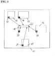
- FIG. 1 schematically shows a structure of the electronic module 11 for the level sensor 10 according to an embodiment of the invention.
- This electronic module 11 comprises a microwave assembly 12, a frequency control module 13, a power supply module 14 for powering the electronic module 11 and the level sensor 10, an interface module 15 and a detector assembly 16.
- the individual modules 12-16 each have a memory 17-21.
- non-volatile memories are used which are electrically programmable and which retain the stored data independently of a power supply.
- serial EEPROMs having a one-wire interface are used. In addition to grounding, these EEPROMs require only a single data line from which they can draw their energy.
- the detector assembly 16 has a microprocessor 22 which is electrically connectable to the individual memories 17-21.
- the electronics assemblies 12 to 15 may additionally include custom microprocessors.
- the individual modules 12 - 16 are installed in identical form in several devices, according to a modular principle.
- the assemblies go through corresponding manufacturing and test steps.
- production-relevant data such as an identification code, in particular a serial number, in the respective memory 17 - 21 of the modules 12 - 16 stored.
- the identification code can provide an indication of the type of assembly and, on the other hand, ensure a clear manufacturer assignment.
- tests such as an automatic optical inspection test (AOI), a test to ensure the explosion protection guidelines (IC test) or functional tests, in particular with regard to fault diagnosis and / or measured value or production deviations, are conceivable as test steps.
- AOI automatic optical inspection test
- IC test explosion protection guidelines
- functional tests in particular with regard to fault diagnosis and / or measured value or production deviations
- test steps With regard to the measured value or production deviations, the deviations from the desired nominal output values of the assemblies are understood for a specific input value or for a specific measured variable. After or during a successful execution of these test steps, this is stored in the respective memory 17-21 of the assemblies 12-16, likewise accumulated, relevant test data are stored. This storage can be done by the already connected for this purpose with the assembly tester.
- Table 1 An example of a possible data content that can be stored in the memories 12-16 is given in Table 1.
- the memory device used in this example has a memory capacity of 128 bytes and goes through four test steps.
- Table 1 is self-explanatory in itself.
- the individual assemblies 12-16 are connected to an electronic module 11 by means of electrical Plug connections or assembled by means of no longer detachable, electrically conductive connection means (eg solder connection).
- the microprocessor 22 After assembling the assemblies 12-16 to the electronics module 11, the microprocessor 22 is electrically connected to the memories 17-21. In a subsequent commissioning of the assembly of the electronic module 11, the individual memories 17-21 are read out by the microprocessor 22.
- the microprocessor 22 can carry out a configuration, a verification and / or a calibration of the individual assemblies, of the electronic module and thus of the sensor.
- the microprocessor 22 can verify the correct composition according to the specifications of the manufacturing order.
- the assembly 12 - 16 can be identified on the basis of production data (eg an identification code or a serial number) or based on test data determined by functional testing of the assemblies, by the data content of the respective memory 17 - 21 with the due to the production order or due to the series of the microprocessor is compared by the microprocessor expected data content.
- the microprocessor 22, the electronic module 11 and thus the level sensor 10 to configure independently.
- different frequencies of the antenna 23 (different radar, microwave or ultrasonic frequencies) or the microwave assembly 12 require different settings of an analog-to-digital converter in the signal processing of the detector assembly 16, wherein the settings of the individual modules 12 - 16 independently coordinated by the microprocessor 22 made can be.
- test data from the respective memories 17-21 is evaluated as to whether all tests have passed successfully and that no assemblies are being delivered that have not passed all tests successfully. For this purpose, the status of the tests is evaluated by means of the read-out memory contents.
- test data such as adjustment values that are individually based on the module
- the calibration data of a D / A converter drive for generating the current output level of the power supply unit 14 is detected in the functional test of the power supply unit 14 and stored as test data in the memory 19 of the power supply unit 14.
- These acquired calibration data may then be used by the microprocessor 22 after assembly of the electronic module to drive the power supply assembly 14 so that the level sensor has the required current output level. Until now this required a manual calibration of the current output at the final balancing position of the level sensors.
- the memory contents of the memories 17-21 comprise an identification code or a unique serial number, the serial number range of each delivery being communicated to the customer during distribution of the components. This serial number can be read in the complete device and thus serve as proof that the electronic module really comes from a specific manufacturer.
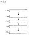
- FIG. 2 shows the inventive method for producing a sensor.
- module-specific data of a plurality of electronic assemblies 12-16 are determined in step S100.
- step S101 the module-specific data in respective memory 17 - 21 of the modules 12 - 16 stored.
- step S102 the modules 12-16 are assembled in an electronic module 11 in step S102, wherein an electronic coupling of the assemblies 12-16 takes place with a processor 22.
- the data thus accessible to the processor 22 are read out in step S103 and evaluated in a subsequent step S104.
Landscapes
- Physics & Mathematics (AREA)
- Electromagnetism (AREA)
- Fluid Mechanics (AREA)
- General Physics & Mathematics (AREA)
- Engineering & Computer Science (AREA)
- Signal Processing (AREA)
- Thermal Sciences (AREA)
- Testing Or Calibration Of Command Recording Devices (AREA)
Priority Applications (3)
| Application Number | Priority Date | Filing Date | Title |
|---|---|---|---|
| EP08168401.1A EP2184591B1 (fr) | 2008-11-05 | 2008-11-05 | Redondance modulaire triple efficace sur un anneau tressé |
| US12/576,559 US9014998B2 (en) | 2008-11-05 | 2009-10-09 | Sensor with subassemblies featuring storage devices |
| CN200910209349.5A CN101738242B (zh) | 2008-11-05 | 2009-11-04 | 具有以存储装置为特征的组件的传感器 |
Applications Claiming Priority (1)
| Application Number | Priority Date | Filing Date | Title |
|---|---|---|---|
| EP08168401.1A EP2184591B1 (fr) | 2008-11-05 | 2008-11-05 | Redondance modulaire triple efficace sur un anneau tressé |
Publications (3)
| Publication Number | Publication Date |
|---|---|
| EP2184591A1 true EP2184591A1 (fr) | 2010-05-12 |
| EP2184591A9 EP2184591A9 (fr) | 2010-12-08 |
| EP2184591B1 EP2184591B1 (fr) | 2016-05-25 |
Family
ID=40512270
Family Applications (1)
| Application Number | Title | Priority Date | Filing Date |
|---|---|---|---|
| EP08168401.1A Not-in-force EP2184591B1 (fr) | 2008-11-05 | 2008-11-05 | Redondance modulaire triple efficace sur un anneau tressé |
Country Status (3)
| Country | Link |
|---|---|
| US (1) | US9014998B2 (fr) |
| EP (1) | EP2184591B1 (fr) |
| CN (1) | CN101738242B (fr) |
Families Citing this family (3)
| Publication number | Priority date | Publication date | Assignee | Title |
|---|---|---|---|---|
| US9243938B2 (en) | 2010-08-04 | 2016-01-26 | Fluke Corporation | Single TEDS electronic data sheet for multiple accelerometers |
| DE102011054462A1 (de) * | 2011-10-13 | 2013-04-18 | Wika Alexander Wiegand Se & Co. Kg | Kontollvorrichtung zur Überwachung des Füllstands eines Tanks, Tankverwaltungsvorrichtung und Verfahren zur Steuerung der Befüllung eines Tanks |
| DE102023207665A1 (de) * | 2023-08-09 | 2025-02-13 | Volkswagen Aktiengesellschaft | Verfahren zur Übergabe von Messwerten und/oder Parametern einer teilbestückten Leiterplatte und Prüfvorrichtung |
Citations (7)
| Publication number | Priority date | Publication date | Assignee | Title |
|---|---|---|---|---|
| US6314023B1 (en) | 2000-06-15 | 2001-11-06 | Motorola, Inc. | Non-volatile programming elements for redundancy and identification in an integrated circuit |
| US6437692B1 (en) * | 1998-06-22 | 2002-08-20 | Statsignal Systems, Inc. | System and method for monitoring and controlling remote devices |
| US20050275527A1 (en) * | 2004-05-27 | 2005-12-15 | Lawrence Kates | Wireless repeater for sensor system |
| US20060179251A1 (en) * | 2005-02-10 | 2006-08-10 | International Business Machines Corporation | Method and apparatus to operate cache-inhibited memory mapped commands to access registers |
| US20060267756A1 (en) * | 2004-05-27 | 2006-11-30 | Lawrence Kates | System and method for high-sensitivity sensor |
| US7184924B1 (en) * | 2005-11-03 | 2007-02-27 | International Business Machines Corporation | Method, apparatus and computer program product for implementing thermal integrity screening |
| WO2007027342A1 (fr) | 2005-08-31 | 2007-03-08 | Lawrence Kates | Procede et dispositif pour detecter la gravite de fuites d'eau |
Family Cites Families (8)
| Publication number | Priority date | Publication date | Assignee | Title |
|---|---|---|---|---|
| US4862067A (en) * | 1987-06-24 | 1989-08-29 | Schlumberger Technologies, Inc. | Method and apparatus for in-circuit testing of electronic devices |
| US5586085A (en) * | 1991-10-31 | 1996-12-17 | Lichte; Leo J. | Container and adaptor for use with fluid volume sensor |
| US6489586B1 (en) * | 1999-04-29 | 2002-12-03 | Cad-Tech, Inc. | Method and apparatus for verification of assembled printed circuit boards |
| US7626508B2 (en) * | 2002-03-05 | 2009-12-01 | Aeromesh Corporation | Monitoring system and method |
| US6882950B1 (en) * | 2003-01-17 | 2005-04-19 | Unisys Corporation | Building and testing complex computer products with contract manufacturers without supplying proprietary information |
| KR100567908B1 (ko) * | 2004-12-30 | 2006-04-05 | 주식회사 하이닉스반도체 | 반도체 소자의 보정 회로 및 그 구동 방법 |
| EP2042829B2 (fr) | 2007-09-26 | 2017-08-09 | Hexagon Metrology AB | Étalonnage modulaire |
| US7818135B2 (en) * | 2008-05-30 | 2010-10-19 | Agere Systems Inc. | Optimum timing of write and read clock paths |
-
2008
- 2008-11-05 EP EP08168401.1A patent/EP2184591B1/fr not_active Not-in-force
-
2009
- 2009-10-09 US US12/576,559 patent/US9014998B2/en not_active Expired - Fee Related
- 2009-11-04 CN CN200910209349.5A patent/CN101738242B/zh not_active Expired - Fee Related
Patent Citations (7)
| Publication number | Priority date | Publication date | Assignee | Title |
|---|---|---|---|---|
| US6437692B1 (en) * | 1998-06-22 | 2002-08-20 | Statsignal Systems, Inc. | System and method for monitoring and controlling remote devices |
| US6314023B1 (en) | 2000-06-15 | 2001-11-06 | Motorola, Inc. | Non-volatile programming elements for redundancy and identification in an integrated circuit |
| US20050275527A1 (en) * | 2004-05-27 | 2005-12-15 | Lawrence Kates | Wireless repeater for sensor system |
| US20060267756A1 (en) * | 2004-05-27 | 2006-11-30 | Lawrence Kates | System and method for high-sensitivity sensor |
| US20060179251A1 (en) * | 2005-02-10 | 2006-08-10 | International Business Machines Corporation | Method and apparatus to operate cache-inhibited memory mapped commands to access registers |
| WO2007027342A1 (fr) | 2005-08-31 | 2007-03-08 | Lawrence Kates | Procede et dispositif pour detecter la gravite de fuites d'eau |
| US7184924B1 (en) * | 2005-11-03 | 2007-02-27 | International Business Machines Corporation | Method, apparatus and computer program product for implementing thermal integrity screening |
Also Published As
| Publication number | Publication date |
|---|---|
| US20100256942A1 (en) | 2010-10-07 |
| CN101738242B (zh) | 2015-03-11 |
| EP2184591B1 (fr) | 2016-05-25 |
| CN101738242A (zh) | 2010-06-16 |
| US9014998B2 (en) | 2015-04-21 |
| EP2184591A9 (fr) | 2010-12-08 |
Similar Documents
| Publication | Publication Date | Title |
|---|---|---|
| DE69809965T2 (de) | Universelle sensorschnittstelle | |
| DE19524551B4 (de) | Elektrisches Energiemeßsystem, Elektrisches Energiemeßgerät sowie Verfahren zum Aufzeichnen von Kalibrierdaten | |
| EP2071342B1 (fr) | Dispositif et procédé de production d'une impulsion de charge définie pour l'exécution d'une mesure de décharge partiel | |
| EP2211147B1 (fr) | Procédé de contrôle du fonctionnement d'une circuit électrique | |
| EP2148177B1 (fr) | Agencement de mesure et procédé de saisie de données de mesure | |
| DE3923545A1 (de) | Vorrichtung und verfahren zum testen von an einer gleichstromquelle angeschlossenen elektrischen verbrauchern eines kraftfahrzeuges | |
| DE102007010978A1 (de) | Verfahren und Vorrichtung zur Unterstützung einer Diagnose eines elektrischen Systems mittels wahrscheinlichkeitsbasierter Fehlerkandidatenermittlung | |
| DE10161401B4 (de) | Feldgerät zur Bestimmung und/oder Überwachung einer Prozessvariablen | |
| EP3614154A1 (fr) | Système de faisceaux de câbles et procédé de vérification de faisceaux de câbles | |
| EP2184591B1 (fr) | Redondance modulaire triple efficace sur un anneau tressé | |
| DE102009055231A1 (de) | Messsystem zum Bestimmen eines Werts einer physikalischen oder chemischen Messgröße eines Mediums und Verfahren zum Betrieb des Messsystems | |
| WO1993007501A1 (fr) | Procede et dispositif pour le controle du cablage entre une armoire electrique et les appareils a champ qui lui sont raccordes | |
| EP2574883A1 (fr) | Procédé de calibrage et/ou d'ajustement d'un capteur, notamment d'un capteur électrochimique, électrophysique ou optique, ainsi que le capteur correspondant | |
| DE102021116906A1 (de) | Test- und messsystem zur analyse von zu testenden vorrichtungen | |
| EP2803956A1 (fr) | Module de service pour un appareil de mesure du niveau de remplissage et procédé de service automatisé | |
| DE102009047535B4 (de) | Verfahren zum Ermitteln einer Anschlusskonfiguration eines Feldgerätes an einem Wireless Adapter | |
| DE102010062657B4 (de) | Bereitstellung von Kalibrierungsdaten zu Messeinrichtungen | |
| EP3232218A2 (fr) | Module d'étalonnage en ligne, dispositif commandé par un programme et système de mesure et d'étalonnage | |
| EP3717170B1 (fr) | Dispositif d'usinage par ultrasons, procédé pour la configuration d'un dispositif d'usinage par ultrasons, système comprenant un tel dispositif d'usinage par ultrasons | |
| EP2492701A1 (fr) | Procédé et dispositif destinés au test d'une éolienne | |
| DE102007041848A1 (de) | Verfahren und Vorrichtung zur Ermittlung von fehlerhaften Komponenten von verkoppelten Wirkketten | |
| EP1791048A1 (fr) | Système d'automatisation comprenant un capteur ou un actionneur identifié par un RFID | |
| WO2014064147A2 (fr) | Procédé pour mesurer l'application d'une haute-tension et constater l'absence de tension | |
| WO2002010782A2 (fr) | Procede et dispositif de controle de defauts dans des lignes electriques et/ou des recepteurs electriques d'un vehicule | |
| DE10148029A1 (de) | Verfahren zur Datensicherung bei einem Feldgerät |
Legal Events
| Date | Code | Title | Description |
|---|---|---|---|
| PUAI | Public reference made under article 153(3) epc to a published international application that has entered the european phase |
Free format text: ORIGINAL CODE: 0009012 |
|
| AK | Designated contracting states |
Kind code of ref document: A1 Designated state(s): AT BE BG CH CY CZ DE DK EE ES FI FR GB GR HR HU IE IS IT LI LT LU LV MC MT NL NO PL PT RO SE SI SK TR |
|
| AX | Request for extension of the european patent |
Extension state: AL BA MK RS |
|
| 17P | Request for examination filed |
Effective date: 20101018 |
|
| AKX | Designation fees paid |
Designated state(s): AT BE BG CH CY CZ DE DK EE ES FI FR GB GR HR HU IE IS IT LI LT LU LV MC MT NL NO PL PT RO SE SI SK TR |
|
| 17Q | First examination report despatched |
Effective date: 20110506 |
|
| GRAP | Despatch of communication of intention to grant a patent |
Free format text: ORIGINAL CODE: EPIDOSNIGR1 |
|
| INTG | Intention to grant announced |
Effective date: 20160104 |
|
| GRAS | Grant fee paid |
Free format text: ORIGINAL CODE: EPIDOSNIGR3 |
|
| GRAA | (expected) grant |
Free format text: ORIGINAL CODE: 0009210 |
|
| AK | Designated contracting states |
Kind code of ref document: B1 Designated state(s): AT BE BG CH CY CZ DE DK EE ES FI FR GB GR HR HU IE IS IT LI LT LU LV MC MT NL NO PL PT RO SE SI SK TR |
|
| REG | Reference to a national code |
Ref country code: GB Ref legal event code: FG4D Free format text: NOT ENGLISH |
|
| REG | Reference to a national code |
Ref country code: CH Ref legal event code: EP |
|
| REG | Reference to a national code |
Ref country code: IE Ref legal event code: FG4D Free format text: LANGUAGE OF EP DOCUMENT: GERMAN Ref country code: AT Ref legal event code: REF Ref document number: 802691 Country of ref document: AT Kind code of ref document: T Effective date: 20160615 |
|
| REG | Reference to a national code |
Ref country code: DE Ref legal event code: R096 Ref document number: 502008014243 Country of ref document: DE |
|
| REG | Reference to a national code |
Ref country code: SE Ref legal event code: TRGR |
|
| REG | Reference to a national code |
Ref country code: LT Ref legal event code: MG4D |
|
| REG | Reference to a national code |
Ref country code: NL Ref legal event code: MP Effective date: 20160525 |
|
| PG25 | Lapsed in a contracting state [announced via postgrant information from national office to epo] |
Ref country code: NO Free format text: LAPSE BECAUSE OF FAILURE TO SUBMIT A TRANSLATION OF THE DESCRIPTION OR TO PAY THE FEE WITHIN THE PRESCRIBED TIME-LIMIT Effective date: 20160825 Ref country code: NL Free format text: LAPSE BECAUSE OF FAILURE TO SUBMIT A TRANSLATION OF THE DESCRIPTION OR TO PAY THE FEE WITHIN THE PRESCRIBED TIME-LIMIT Effective date: 20160525 Ref country code: LT Free format text: LAPSE BECAUSE OF FAILURE TO SUBMIT A TRANSLATION OF THE DESCRIPTION OR TO PAY THE FEE WITHIN THE PRESCRIBED TIME-LIMIT Effective date: 20160525 Ref country code: FI Free format text: LAPSE BECAUSE OF FAILURE TO SUBMIT A TRANSLATION OF THE DESCRIPTION OR TO PAY THE FEE WITHIN THE PRESCRIBED TIME-LIMIT Effective date: 20160525 |
|
| PG25 | Lapsed in a contracting state [announced via postgrant information from national office to epo] |
Ref country code: GR Free format text: LAPSE BECAUSE OF FAILURE TO SUBMIT A TRANSLATION OF THE DESCRIPTION OR TO PAY THE FEE WITHIN THE PRESCRIBED TIME-LIMIT Effective date: 20160826 Ref country code: HR Free format text: LAPSE BECAUSE OF FAILURE TO SUBMIT A TRANSLATION OF THE DESCRIPTION OR TO PAY THE FEE WITHIN THE PRESCRIBED TIME-LIMIT Effective date: 20160525 Ref country code: PT Free format text: LAPSE BECAUSE OF FAILURE TO SUBMIT A TRANSLATION OF THE DESCRIPTION OR TO PAY THE FEE WITHIN THE PRESCRIBED TIME-LIMIT Effective date: 20160926 Ref country code: LV Free format text: LAPSE BECAUSE OF FAILURE TO SUBMIT A TRANSLATION OF THE DESCRIPTION OR TO PAY THE FEE WITHIN THE PRESCRIBED TIME-LIMIT Effective date: 20160525 Ref country code: ES Free format text: LAPSE BECAUSE OF FAILURE TO SUBMIT A TRANSLATION OF THE DESCRIPTION OR TO PAY THE FEE WITHIN THE PRESCRIBED TIME-LIMIT Effective date: 20160525 |
|
| PG25 | Lapsed in a contracting state [announced via postgrant information from national office to epo] |
Ref country code: IT Free format text: LAPSE BECAUSE OF FAILURE TO SUBMIT A TRANSLATION OF THE DESCRIPTION OR TO PAY THE FEE WITHIN THE PRESCRIBED TIME-LIMIT Effective date: 20160525 |
|
| PG25 | Lapsed in a contracting state [announced via postgrant information from national office to epo] |
Ref country code: DK Free format text: LAPSE BECAUSE OF FAILURE TO SUBMIT A TRANSLATION OF THE DESCRIPTION OR TO PAY THE FEE WITHIN THE PRESCRIBED TIME-LIMIT Effective date: 20160525 Ref country code: CZ Free format text: LAPSE BECAUSE OF FAILURE TO SUBMIT A TRANSLATION OF THE DESCRIPTION OR TO PAY THE FEE WITHIN THE PRESCRIBED TIME-LIMIT Effective date: 20160525 Ref country code: RO Free format text: LAPSE BECAUSE OF FAILURE TO SUBMIT A TRANSLATION OF THE DESCRIPTION OR TO PAY THE FEE WITHIN THE PRESCRIBED TIME-LIMIT Effective date: 20160525 Ref country code: EE Free format text: LAPSE BECAUSE OF FAILURE TO SUBMIT A TRANSLATION OF THE DESCRIPTION OR TO PAY THE FEE WITHIN THE PRESCRIBED TIME-LIMIT Effective date: 20160525 Ref country code: SK Free format text: LAPSE BECAUSE OF FAILURE TO SUBMIT A TRANSLATION OF THE DESCRIPTION OR TO PAY THE FEE WITHIN THE PRESCRIBED TIME-LIMIT Effective date: 20160525 |
|
| PG25 | Lapsed in a contracting state [announced via postgrant information from national office to epo] |
Ref country code: BE Free format text: LAPSE BECAUSE OF NON-PAYMENT OF DUE FEES Effective date: 20161130 Ref country code: PL Free format text: LAPSE BECAUSE OF FAILURE TO SUBMIT A TRANSLATION OF THE DESCRIPTION OR TO PAY THE FEE WITHIN THE PRESCRIBED TIME-LIMIT Effective date: 20160525 |
|
| REG | Reference to a national code |
Ref country code: DE Ref legal event code: R097 Ref document number: 502008014243 Country of ref document: DE |
|
| PLBE | No opposition filed within time limit |
Free format text: ORIGINAL CODE: 0009261 |
|
| STAA | Information on the status of an ep patent application or granted ep patent |
Free format text: STATUS: NO OPPOSITION FILED WITHIN TIME LIMIT |
|
| 26N | No opposition filed |
Effective date: 20170228 |
|
| PG25 | Lapsed in a contracting state [announced via postgrant information from national office to epo] |
Ref country code: SI Free format text: LAPSE BECAUSE OF FAILURE TO SUBMIT A TRANSLATION OF THE DESCRIPTION OR TO PAY THE FEE WITHIN THE PRESCRIBED TIME-LIMIT Effective date: 20160525 |
|
| REG | Reference to a national code |
Ref country code: CH Ref legal event code: PL |
|
| PG25 | Lapsed in a contracting state [announced via postgrant information from national office to epo] |
Ref country code: LI Free format text: LAPSE BECAUSE OF NON-PAYMENT OF DUE FEES Effective date: 20161130 Ref country code: CH Free format text: LAPSE BECAUSE OF NON-PAYMENT OF DUE FEES Effective date: 20161130 |
|
| REG | Reference to a national code |
Ref country code: IE Ref legal event code: MM4A |
|
| REG | Reference to a national code |
Ref country code: FR Ref legal event code: ST Effective date: 20170731 |
|
| PG25 | Lapsed in a contracting state [announced via postgrant information from national office to epo] |
Ref country code: LU Free format text: LAPSE BECAUSE OF NON-PAYMENT OF DUE FEES Effective date: 20161130 |
|
| PG25 | Lapsed in a contracting state [announced via postgrant information from national office to epo] |
Ref country code: FR Free format text: LAPSE BECAUSE OF NON-PAYMENT OF DUE FEES Effective date: 20161130 |
|
| PG25 | Lapsed in a contracting state [announced via postgrant information from national office to epo] |
Ref country code: IE Free format text: LAPSE BECAUSE OF NON-PAYMENT OF DUE FEES Effective date: 20161105 |
|
| REG | Reference to a national code |
Ref country code: AT Ref legal event code: MM01 Ref document number: 802691 Country of ref document: AT Kind code of ref document: T Effective date: 20161105 |
|
| PG25 | Lapsed in a contracting state [announced via postgrant information from national office to epo] |
Ref country code: AT Free format text: LAPSE BECAUSE OF NON-PAYMENT OF DUE FEES Effective date: 20161105 |
|
| REG | Reference to a national code |
Ref country code: BE Ref legal event code: MM Effective date: 20161130 |
|
| PG25 | Lapsed in a contracting state [announced via postgrant information from national office to epo] |
Ref country code: CY Free format text: LAPSE BECAUSE OF FAILURE TO SUBMIT A TRANSLATION OF THE DESCRIPTION OR TO PAY THE FEE WITHIN THE PRESCRIBED TIME-LIMIT Effective date: 20160525 Ref country code: HU Free format text: LAPSE BECAUSE OF FAILURE TO SUBMIT A TRANSLATION OF THE DESCRIPTION OR TO PAY THE FEE WITHIN THE PRESCRIBED TIME-LIMIT; INVALID AB INITIO Effective date: 20081105 |
|
| PG25 | Lapsed in a contracting state [announced via postgrant information from national office to epo] |
Ref country code: MC Free format text: LAPSE BECAUSE OF FAILURE TO SUBMIT A TRANSLATION OF THE DESCRIPTION OR TO PAY THE FEE WITHIN THE PRESCRIBED TIME-LIMIT Effective date: 20160525 Ref country code: TR Free format text: LAPSE BECAUSE OF FAILURE TO SUBMIT A TRANSLATION OF THE DESCRIPTION OR TO PAY THE FEE WITHIN THE PRESCRIBED TIME-LIMIT Effective date: 20160525 Ref country code: IS Free format text: LAPSE BECAUSE OF FAILURE TO SUBMIT A TRANSLATION OF THE DESCRIPTION OR TO PAY THE FEE WITHIN THE PRESCRIBED TIME-LIMIT Effective date: 20160525 |
|
| PG25 | Lapsed in a contracting state [announced via postgrant information from national office to epo] |
Ref country code: BG Free format text: LAPSE BECAUSE OF FAILURE TO SUBMIT A TRANSLATION OF THE DESCRIPTION OR TO PAY THE FEE WITHIN THE PRESCRIBED TIME-LIMIT Effective date: 20160525 |
|
| PG25 | Lapsed in a contracting state [announced via postgrant information from national office to epo] |
Ref country code: MT Free format text: LAPSE BECAUSE OF FAILURE TO SUBMIT A TRANSLATION OF THE DESCRIPTION OR TO PAY THE FEE WITHIN THE PRESCRIBED TIME-LIMIT Effective date: 20160525 |
|
| PGFP | Annual fee paid to national office [announced via postgrant information from national office to epo] |
Ref country code: GB Payment date: 20211123 Year of fee payment: 14 Ref country code: SE Payment date: 20211123 Year of fee payment: 14 Ref country code: DE Payment date: 20211122 Year of fee payment: 14 |
|
| REG | Reference to a national code |
Ref country code: DE Ref legal event code: R119 Ref document number: 502008014243 Country of ref document: DE |
|
| P01 | Opt-out of the competence of the unified patent court (upc) registered |
Effective date: 20230524 |
|
| REG | Reference to a national code |
Ref country code: SE Ref legal event code: EUG |
|
| GBPC | Gb: european patent ceased through non-payment of renewal fee |
Effective date: 20221105 |
|
| PG25 | Lapsed in a contracting state [announced via postgrant information from national office to epo] |
Ref country code: SE Free format text: LAPSE BECAUSE OF NON-PAYMENT OF DUE FEES Effective date: 20221106 |
|
| PG25 | Lapsed in a contracting state [announced via postgrant information from national office to epo] |
Ref country code: GB Free format text: LAPSE BECAUSE OF NON-PAYMENT OF DUE FEES Effective date: 20221105 Ref country code: DE Free format text: LAPSE BECAUSE OF NON-PAYMENT OF DUE FEES Effective date: 20230601 |