EP2184548B1 - Verfahren und Vorrichtung zum Betreiben einer Solaranlage - Google Patents
Verfahren und Vorrichtung zum Betreiben einer Solaranlage Download PDFInfo
- Publication number
- EP2184548B1 EP2184548B1 EP09175076.0A EP09175076A EP2184548B1 EP 2184548 B1 EP2184548 B1 EP 2184548B1 EP 09175076 A EP09175076 A EP 09175076A EP 2184548 B1 EP2184548 B1 EP 2184548B1
- Authority
- EP
- European Patent Office
- Prior art keywords
- solar
- sensor
- fluid
- solar fluid
- acted
- Prior art date
- Legal status (The legal status is an assumption and is not a legal conclusion. Google has not performed a legal analysis and makes no representation as to the accuracy of the status listed.)
- Not-in-force
Links
Images
Classifications
-
- F—MECHANICAL ENGINEERING; LIGHTING; HEATING; WEAPONS; BLASTING
- F24—HEATING; RANGES; VENTILATING
- F24D—DOMESTIC- OR SPACE-HEATING SYSTEMS, e.g. CENTRAL HEATING SYSTEMS; DOMESTIC HOT-WATER SUPPLY SYSTEMS; ELEMENTS OR COMPONENTS THEREFOR
- F24D19/00—Details
- F24D19/10—Arrangement or mounting of control or safety devices
- F24D19/1006—Arrangement or mounting of control or safety devices for water heating systems
- F24D19/1066—Arrangement or mounting of control or safety devices for water heating systems for the combination of central heating and domestic hot water
- F24D19/1075—Arrangement or mounting of control or safety devices for water heating systems for the combination of central heating and domestic hot water the system uses solar energy
-
- Y—GENERAL TAGGING OF NEW TECHNOLOGICAL DEVELOPMENTS; GENERAL TAGGING OF CROSS-SECTIONAL TECHNOLOGIES SPANNING OVER SEVERAL SECTIONS OF THE IPC; TECHNICAL SUBJECTS COVERED BY FORMER USPC CROSS-REFERENCE ART COLLECTIONS [XRACs] AND DIGESTS
- Y02—TECHNOLOGIES OR APPLICATIONS FOR MITIGATION OR ADAPTATION AGAINST CLIMATE CHANGE
- Y02B—CLIMATE CHANGE MITIGATION TECHNOLOGIES RELATED TO BUILDINGS, e.g. HOUSING, HOUSE APPLIANCES OR RELATED END-USER APPLICATIONS
- Y02B10/00—Integration of renewable energy sources in buildings
- Y02B10/20—Solar thermal
-
- Y—GENERAL TAGGING OF NEW TECHNOLOGICAL DEVELOPMENTS; GENERAL TAGGING OF CROSS-SECTIONAL TECHNOLOGIES SPANNING OVER SEVERAL SECTIONS OF THE IPC; TECHNICAL SUBJECTS COVERED BY FORMER USPC CROSS-REFERENCE ART COLLECTIONS [XRACs] AND DIGESTS
- Y02—TECHNOLOGIES OR APPLICATIONS FOR MITIGATION OR ADAPTATION AGAINST CLIMATE CHANGE
- Y02B—CLIMATE CHANGE MITIGATION TECHNOLOGIES RELATED TO BUILDINGS, e.g. HOUSING, HOUSE APPLIANCES OR RELATED END-USER APPLICATIONS
- Y02B10/00—Integration of renewable energy sources in buildings
- Y02B10/70—Hybrid systems, e.g. uninterruptible or back-up power supplies integrating renewable energies
Definitions
- the invention relates to a method and a device for operating a solar system, in particular for the optimized maintenance of a solar system according to the preamble of patent claim 1.
- Solar systems for the heating of drinking or service water and the heating support consist essentially of at least one solar collector, a solar circuit with a pump for promoting a heat transfer medium, a control device and a heat consumer, usually a hot water tank with an integrated heat exchanger for transferring heat from the solar circuit to the water content.
- the temperature of the heat transfer medium is detected at the flow of at least one solar collector. It is common practice that the pump in the solar circuit at temperatures above about 120 ° C at the flow of the solar collector no longer starts and / or is taken out of the normal operation of the scheme. There is then the so-called stagnation.
- the pump shut-off serves as an overheating protection for the system, for example to avoid too high temperatures in the hot water tank, which may lead to increased calcification.
- the solar collectors are also subject to high loads due to the intense sunlight, especially in or near the stagnation case.
- Such shutdowns of the solar system due to overheating can be caused, for example, when in the hot water tank due to high temperatures no solar heat can be introduced more, and forms steam in the solar collectors.
- the pump in the solar circuit remains locked, otherwise there would be harmful steam shocks in the area of the solar collectors and piping, if with normal flow pump operation would restart from such an overheating state.
- the solar fluid For example, its pH is checked and the antifreeze properties are determined with a refractometer. Depending on the measurement or even routinely, the solar fluid may be replaced.
- the EP 1860383 A2 discloses a method for operating a solar system with at least two collector fields, with the swapped in the respective collector fields collector temperature sensor, reversed storage temperature sensor and / or reversed pumps are detected.
- the invention has for its object to ensure the optimal function of a solar system on the quality of the solar fluid.
- the efindungshunte method for operating a solar system in which the state of the solar fluid via an output signal of an installed in the solar circuit, acted upon with solar fluid sensor is detected and evaluated in the control device, characterized in that the acted upon with solar fluid sensor properties for measuring the pH Value that possesses permittivity and / or conductivity.
- the maintenance facility issues a maintenance message as a function of the assessed condition.
- the limit value is preferably factory set and can be varied by the installer or operator of the system if necessary.
- a signal evaluation electronics initially processes a raw signal of the sensor with regard to the quality of the solar fluid.
- the sensor supplies either an analog or a digital value to the control device. For example, the value zero would mean that the quality is okay, and the value one, that a maintenance message is required.
- the control device processes the corresponding signal and derives a maintenance message from it.
- the solar fluid-loaded sensor has self-calibration means for avoiding and correcting measurement errors.
- a base value is stored in the signal evaluation electronics and / or in the control device, which is characteristic of the solar fluid used in each case in combination with the respective system situation.
- this basic value is determined either by manual triggering, for example, during startup or after maintenance work, or at regular intervals with a base value measurement.
- the inventive device for operating a solar system in which a solar fluid acted upon sensor is arranged in the solar circuit, which is adapted to detect the state of the solar fluid and to provide an output signal, wherein the control device is adapted to evaluate the output signal is characterized in that the sensor acted upon by solar fluid belongs to the group of pH sensors, capacitive sensors and / or resistive sensors.
- capacitive or resistive sensors are preferred.
- a suitable capacitive sensor consists of two conductive electrodes, for example of metal or conductive plastic, which are isolated from the fluid arranged so that the fluid can flow through these electrodes. About a measurement with AC voltage or current, preferably in the range up to 250 kHz, the capacitance of the device is measured.
- a resistive sensor two electrically conductive electrodes, for example of metal or conductive plastic, in contact with the solar fluid.
- the resistance between the electrodes is measured by means of applied DC or AC voltage or a DC or AC current and is a measure of the aging of the fluid.
- the acted upon with solar fluid sensor for detecting the state of the solar fluid may be formed combined with a temperature sensor.
- the sensor can also be provided as an independent component with integrated signal evaluation electronics and housing or it is integrated into another component of the solar circuit.
- the senor has self-calibration means for avoiding and correcting measurement errors.
- the self-calibration means of the sensor are multi-channel, so that in particular an internal calibration and a calibration to the medium, d. H. to the solar fluid, can be performed.
- a maintenance message is issued directly depending on the condition of the solar fluid, and thereby the optimum maintenance timing adapted to a plant is accurately determined. Due to the improved monitoring of the solar fluid, the service life of a solar collector is extended and the optimal function of a solar system ensured since possible damage caused by an unsuitable or changed in its properties solar fluid, for example, with limited antifreeze properties or lump formation, prevented or at least significantly reduced.
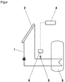
- the drawing illustrates an embodiment of the invention and shows in the single figure schematically a solar system with a sensor according to the invention.
- the solar system has a solar fluid as a heat transfer medium in a solar circuit 1 via at least one solar collector 2 and at least one heat consumer 3 and a control device. 4
- the state of the solar fluid is detected via an output signal of a built-in solar circuit 1, acted upon by solar fluid sensor 5.
- a signal evaluation electronics 6 first processes a raw signal of the sensor 5 with regard to the quality of the solar fluid, and transmits a signal to the control device 4 if the quality of the solar fluid falls below a definable limit value which characterizes the achievement of a critical solar fluid condition. On this basis, the control device 4, if necessary, a maintenance message.
Landscapes
- Engineering & Computer Science (AREA)
- Chemical & Material Sciences (AREA)
- Sustainable Development (AREA)
- Sustainable Energy (AREA)
- Physics & Mathematics (AREA)
- Thermal Sciences (AREA)
- Life Sciences & Earth Sciences (AREA)
- Combustion & Propulsion (AREA)
- Mechanical Engineering (AREA)
- General Engineering & Computer Science (AREA)
- Photovoltaic Devices (AREA)
- Investigating Or Analyzing Materials By The Use Of Electric Means (AREA)
- Engine Equipment That Uses Special Cycles (AREA)
Description
- Die Erfindung betrifft ein Verfahren und eine Vorrichtung zum Betreiben einer Solaranlage, insbesondere zur optimierten Wartung eines Solarsystems nach dem Oberbegriff des Patentanspruches 1.
- Solaranlagen für die Erwärmung von Trink- oder Brauchwasser sowie die Heizungsunterstützung bestehen im Wesentlichen aus mindestens einem Solarkollektor, einem Solarkreislauf mit einer Pumpe zur Förderung eines Wärmeträgermediums, einer Regeleinrichtung und einem Wärmeverbraucher, meistens einem Warmwasserspeicher mit einem integrierten Wärmetauscher zur Übertragung der Wärme aus dem Solarkreislauf an den Wasserinhalt.
- Mit einem Temperaturfühler wird die Temperatur des Wärmeträgermediums am Vorlauf mindestens eines Solarkollektors erfasst. Dabei ist es allgemein üblich, dass die Pumpe im Solarkreislauf bei Temperaturen über etwa 120 °C am Vorlauf des Solarkollektors nicht mehr anläuft und/oder aus dem Normalbetrieb der Regelung herausgenommen wird. Es liegt dann die sogenannte Stagnation vor. Die Pumpenabschaltung dient als Überhitzungsschutz für die Anlage, zum Beispiel um zu hohe Temperaturen im Warmwasserspeicher, die möglicherweise eine verstärkte Kalkbildung nach sich ziehen, zu vermeiden.
- Aber auch die Solarkollektoren unterliegen aufgrund der intensiven Sonneneinstrahlung hohen Belastungen, besonders im oder nahe dem Stagnationsfall. Solche Abschaltungen der Solaranlage durch Überhitzungen können beispielsweise verursacht werden, wenn in den Warmwasserspeicher wegen zu hoher Temperaturen keine Solarwärme mehr eingebracht werden kann, und sich in den Solarkollektoren Dampf bildet. Die Pumpe im Solarkreislauf bleibt gesperrt, weil es sonst zu schädlichen Dampfschlägen im Bereich der Solarenkollektoren und Rohrleitungen kommen würde, wenn mit normaler Fördermenge der Pumpenbetrieb aus einem derartigen Überhitzungszustand wieder anlaufen würde.
- Weiterhin wird dabei ein Solarfluid, welches den Solarkollektor bzw. den Kreislauf im Solarsystem durchströmt, erhöhten Temperaturbelastungen ausgesetzt. Dies bewirkt einen Verschleiß, welcher bei einem Solarfluid auch durch den Begriff "Stress" beschrieben wird. Dabei kommt es zum sogenannten Cracken innerhalb des meistens verwendeten Glycol-Wasser-Gemisches, wobei beispielsweise die Frostschutzeigenschaften schlechter werden. Im Stand der Technik gibt es verschiedene Lösungen, Stressbereiche für ein Solarfluid zu vermeiden. Jedoch lassen sich Stressbereiche nicht vollständig vermeiden, weil diese von verschiedenen Nutzungs-, Auslegungs-, Komponenten- und Betriebseinflüssen abhängen. Daher lässt sich der genaue Zeitpunkt einer notwendigen Wartung bisher nicht genau für die jeweilige Anlage vorhersagen.
- Bei einer Wartung des Solarfluides werden beispielsweise dessen pH-Wert überprüft und die Frostschutzeigenschaften mit einem Refraktometer bestimmt. Abhängig von der Messung oder auch routinemäßig wird dann eventuell das Solarfluid ausgetauscht.
- Die
EP 1860383 A2 offenbart ein Verfahren zum Betreiben einer Solaranlage mit mindestens zwei Kollektorfeldern, mit dem in den jeweiligen Kollektorfeldern vertauschte Kollektortemperaturfühler, vertauschte Speichertemperaturfühler und/oder vertauschte Pumpen erkannt werden. - Der Erfindung liegt die Aufgabe zugrunde, die optimale Funktion eines Solarsystems über die Qualität des Solarfluids sicherzustellen.
- Erfindungsgemäß wird dies durch die Gegenstände mit den Merkmalen des Patentanspruches 1 und des Patentanspruches 6 gelöst. Vorteilhafte Weiterbildungen sind den Unteransprüchen zu entnehmen.
- Das efindungsgemäße Verfahren zum Betreiben einer Solaranlage, bei dem der Zustand des Solarfluids über ein Ausgangssignal eines im Solarkreislauf eingebauten, mit Solarfluid beaufschlagten Sensors erfasst und in der Regeleinrichtung ausgewertet wird, ist dadurch gekennzeichnet, dass der mit Solarfluid beaufschlagte Sensor Eigenschaften zur Messung des pH-Wertes, der Permittivität und/oder der Leitfähigkeit besitzt.
- Wenn die Qualität des Solarfluids einen festlegbaren Grenzwert unterschreitet, welcher das Erreichen eines kritischen Solarfluidzustandes charakterisiert, wird von der Regeleinrichtung eine Wartungsmeldung in Abhängigkeit des bewerteten Zustands ausgegeben. Dabei ist der Grenzwert vorzugsweise werksseitig vorgegeben und kann bei Bedarf vom Installateur oder Betreiber der Anlage variiert werden.
- Eine Signalauswerteelektronik verarbeitet zunächst ein Rohsignal des Sensors hinsichtlich der Qualität des Solarfluids. Dabei liefert der Sensor entweder einen analogen oder einen digitalen Wert an die Regeleinrichtung. Zum Beispiel würde der Wert Null bedeuten, dass die Qualität in Ordnung ist, und der Wert Eins, dass eine Wartungsmeldung erforderlich ist. Die Regeleinrichtung verarbeitet das entsprechende Signal und leitet daraus eine Wartungsmeldung ab.
- Weiterhin besitzt der mit Solarfluid beaufschlagte Sensor Eigenkalibrierungsmittel zur Vermeidung und Korrektur von Messfehlern. Dazu ist in der Signalauswerteelektronik und/oder in der Regeleinrichtung ein Basiswert hinterlegt, welcher charakteristisch für das jeweils verwendete Solarfluid in Kombination mit der jeweiligen Anlagensituation ist. Für die Eigenkalibrierung des Sensors wird dieser Basiswert entweder durch manuelle Auslösung, beispielsweise bei Inbetriebnahme oder nach Wartungsarbeiten, oder in regelmäßigen Zeitabständen mit einer Basiswertmessung bestimmt.
- Die erfindungsgemäße Vorrichtung zum Betreiben einer Solaranlage, bei der ein mit Solarfluid beaufschlagter Sensor im Solarkreislauf angeordnet ist, welcher dazu geeignet ist, den Zustand des Solarfluids zu erfassen und ein Ausgangssignal zu liefern, wobei die Regeleinrichtung dazu geeignet ist, das Ausgangssignal auszuwerten, ist dadurch gekennzeichnet, dass der mit Solarfluid beaufschlagte Sensor zu der Gruppe der pH-WertSensoren, der kapazitiven Sensoren und/oder der resistiven Sensoren gehört. Dabei werden kapazitive oder resistive Sensoren bevorzugt. Ein geeigneter kapazitiver Sensor besteht aus zwei leitfähigen Elektroden, beispielsweise aus Metall oder leitfähigem Kunststoff, welche isoliert vom Fluid so angeordnet sind, so dass das Fluid diese Elektroden durchfließen kann. Über eine Messung mit Wechselspannung oder -strom, bevorzugt im Bereich bis 250 kHz, wird die Kapazität der Anordnung gemessen. Diese korreliert dann mit dem Alterungszustand des Fluids. Dagegen sind bei einem resistiven Sensor zwei elektrisch leitende Elektroden, beispielsweise aus Metall oder leitfähigem Kunststoff, in Kontakt mit dem Solarfluid. Der Widerstand zwischen den Elektroden wird mittels angelegter Gleich- oder Wechselspannung oder einem Gleich- oder Wechselstrom gemessen und ist ein Maß für die Alterung des Fluids.
- Der mit Solarfluid beaufschlagte Sensor zur Erfassung des Zustandes des Solarfluids kann mit einem Temperatursensor kombiniert ausgebildet sein. Weiterhin kann der Sensor auch als eigenständiges Bauteil mit integrierter Signalauswerteelektronik und Gehäuse versehen sein oder er wird in ein anderes Bauteil des Solarkreislaufs integriert.
- Vorzugsweise besitzt der Sensor Eigenkalibrierungsmittel zur Vermeidung und Korrektur von Messfehlem. Dabei sind die Eigenkalibrierungsmittel des Sensors mehrkanalig ausgeführt, so dass insbesondere eine interne Kalibrierung und eine Kalibrierung zum Medium, d. h. zum Solarfluid, durchgeführt werden kann.
- Mit dem erfindungsgemäßen Verfahren und der erfindungsgemäßen Vorrichtung werden die optimale Funktion eines Solarsystems über die Qualität des Solarfluids sichergestellt und die folgenden Vorteile realisiert:
- Eine Wartungsmeldung wird direkt abhängig von dem Zustand des Solarfluids ausgegeben und dadurch wird der an eine Anlage angepasste, optimale Wartungszeitpunkt genau bestimmt. Durch die verbesserte Überwachung des Solarfluids wird die Standzeit eines Solarkollektors verlängert und die optimale Funktion eines Solarsystems sichergestellt, da mögliche Schäden durch ein nicht geeignetes oder in seinen Eigenschaften verändertes Solarfluid, beispielsweise mit eingeschränkten Frostschutzeigenschaften oder Klumpenbildung, verhindert oder zumindest deutlich verringert werden.
- Die Zeichnung stellt ein Ausführungsbeispiel der Erfindung dar und zeigt in der einzigen Figur schematisch ein Solarsystem mit einem erfindungsgemäßen Sensor.
- Das Solarsystem besitzt ein Solarfluid als Wärmeträgermedium in einem Solarkreislauf 1 über mindestens einen Solarkollektor 2 und mindestens einen Wärmeverbraucher 3 sowie eine Regeleinrichtung 4.
- Der Zustand des Solarfluids wird über ein Ausgangssignal eines im Solarkreislauf 1 eingebauten, mit Solarfluid beaufschlagten Sensors 5 erfasst.
- Eine Signalauswerteelektronik 6 verarbeitet zuerst ein Rohsignal des Sensors 5 hinsichtlich der Qualität des Solarfluids, und gibt ein Signal die Regeleinrichtung 4 weiter, wenn die Qualität des Solarfluids einen festlegbaren Grenzwert, welcher das Erreichen eines kritischen Solarfluidzustandes charakterisiert, unterschreitet. Auf dieser Basis leitet die Regeleinrichtung 4, wenn erforderlich, eine Wartungsmeldung ab.
Claims (11)
- Verfahren zum Betreiben einer Solaranlage, insbesondere zur optimierten Wartung eines Solarsystems, mit Solarfluid als Wärmeträgermedium in einem Solarkreislauf (1) über mindestens einen Solarkollektor (2) und mindestens einen Wärmeverbraucher (3) sowie mit einer Regeleinrichtung (4), wobei der Zustand des Solarfluids über ein Ausgangssignal eines im Solarkreislauf (1) eingebauten, mit Solarfluid beaufschlagten Sensors (5) erfasst und in der Regeleinrichtung (4) ausgewertet wird,
dadurch gekennzeichnet, dass der mit Solarfluid beaufschlagte Sensor (5) Eigenschaften zur Messung des pH-Wertes, der Permittivität und/oder der Leitfähigkeit besitzt. - Verfahren nach Anspruch 1,
dadurch gekennzeichnet, dass von der Regeleinrichtung (4) eine Wartungsmeldung in Abhängigkeit des bewerteten Zustands ausgegeben wird, wenn die Qualität des Solarfluids einen festlegbaren Grenzwert, welcher das Erreichen eines kritischen Solarfluidzustandes charakterisiert, unterschreitet. - Verfahren nach Anspruch 1 oder 2,
dadurch gekennzeichnet, dass eine Signalauswerteelektronik (6) ein Rohsignal des Sensors (5) hinsichtlich der Qualität des Solarfluids vorverarbeitet, wobei der Sensor (5) entweder einen analogen oder einen digitalen Wert an die Regeleinrichtung (4) liefert, und dass die Regeleinrichtung (4) dieses Signal verarbeitet und daraus eine Wartungsmeldung ableitet. - Verfahren nach einem der Ansprüche 1 bis 3,
dadurch gekennzeichnet, dass der mit Solarfluid beaufschlagte Sensor (5) Eigenkalibrierungsmittel zur Vermeidung und Korrektur von Messfehlern besitzt, wobei ein Basiswert hinterlegt ist, welcher charakteristisch für das jeweils verwendete Solarfluid in Kombination mit der jeweiligen Anlagensituation ist. - Verfahren nach Anspruch 4,
dadurch gekennzeichnet, dass für die Eigenkalibrierung des Sensors (5) ein Basiswert, welcher charakteristisch für das jeweils verwendete Solarfluid in Kombination mit der jeweiligen Anlagensituation ist, durch manuelle Auslösung oder in regelmäßigen Zeitabständen mit einer Basiswertmessung bestimmt wird. - Vorrichtung zum Betreiben einer Solaranlage und zur Durchführung des Verfahrens nach mindestens einem der vorstehenden Ansprüche, insbesondere zur optimierten Wartung eines Solarsystems, mit einem Solarkreislauf (1), den ein Solarfluid als Wärmeträgermedium über mindestens einen Solarkollektor (2) und mindestens einen Wärmeverbraucher (3) durchströmt, mit einer Regeleinrichtung (4) sowie mit einem im Solarkreislauf (1) angeordneten und mit Solarfluid beaufschlagten Sensor (5), welcher dazu geeignet ist, den Zustand des Solarfluids zu erfassen und ein Ausgangssignal zu liefern, wobei die Regeleinrichtung (4) dazu geeignet ist, das Ausgangssignal auszuwerten,
dadurch gekennzeichnet, dass der mit Solarfluid beaufschlagte Sensor (5) ein Sensor aus der Gruppe der pH-Wert-Sensoren, der kapazitiven Sensoren und/oder der resistiven Sensoren ist. - Vorrichtung nach Anspruch 6,
dadurch gekennzeichnet, dass der mit Solarfluid beaufschlagte Sensor (5) zur Erfassung des Zustandes des Solarfluids mit einem Temperatursensor kombiniert ausgebildet ist. - Vorrichtung nach Anspruch 6 oder 7,
dadurch gekennzeichnet, dass der mit Solarfluid beaufschlagte Sensor (5) als eigenständiges Bauteil mit integrierter Signalauswerteelektronik (6) und Gehäuse ausgebildet ist. - Vorrichtung nach einem der Ansprüche 6 bis 8,
dadurch gekennzeichnet, dass der mit Solarfluid beaufschlagte Sensor (5) in ein anderes Bauteil des Solarkreislaufs integriert ist. - Vorrichtung nach einem der Ansprüche 6 bis 9,
dadurch gekennzeichnet, dass der mit Solarfluid beaufschlagte Sensor (5) Eigenkalibrierungsmittel zur Vermeidung und Korrektur von Messfehlern besitzt. - Vorrichtung nach Anspruch 10,
dadurch gekennzeichnet, dass die Eigenkalibrierungsmittel des Sensors (5) mehrkanalig, insbesondere für eine interne Kalibrierung und eine Kalibrierung zum Solarfluid, ausgeführt sind.
Applications Claiming Priority (1)
| Application Number | Priority Date | Filing Date | Title |
|---|---|---|---|
| DE102008056509A DE102008056509B4 (de) | 2008-11-08 | 2008-11-08 | Verfahren und Vorrichtung zum Betreiben einer Solaranlage |
Publications (3)
| Publication Number | Publication Date |
|---|---|
| EP2184548A2 EP2184548A2 (de) | 2010-05-12 |
| EP2184548A3 EP2184548A3 (de) | 2015-01-07 |
| EP2184548B1 true EP2184548B1 (de) | 2016-06-29 |
Family
ID=41625835
Family Applications (1)
| Application Number | Title | Priority Date | Filing Date |
|---|---|---|---|
| EP09175076.0A Not-in-force EP2184548B1 (de) | 2008-11-08 | 2009-11-05 | Verfahren und Vorrichtung zum Betreiben einer Solaranlage |
Country Status (4)
| Country | Link |
|---|---|
| EP (1) | EP2184548B1 (de) |
| DE (1) | DE102008056509B4 (de) |
| ES (1) | ES2593355T3 (de) |
| PT (1) | PT2184548T (de) |
Families Citing this family (1)
| Publication number | Priority date | Publication date | Assignee | Title |
|---|---|---|---|---|
| CN105605667A (zh) * | 2016-03-03 | 2016-05-25 | 谭汉卿 | 一种太阳能取暖智能控制系统 |
Family Cites Families (5)
| Publication number | Priority date | Publication date | Assignee | Title |
|---|---|---|---|---|
| US5206819A (en) * | 1990-09-06 | 1993-04-27 | Illing Wesley R | Control system for solar heater |
| DE10257309A1 (de) * | 2002-11-30 | 2004-06-09 | Gast, Karl Heinz, Dipl.-Ing. (FH) | Verfahren und Einrichtungen zum Frostschutz in Heizungsanlagen |
| DE10320347B4 (de) * | 2003-05-07 | 2007-06-28 | Karl Kargl | Sprühanlage |
| DE202005015303U1 (de) * | 2004-12-12 | 2006-09-28 | Kern, Richard | Ökonomisches Fassadenelement mit Lichtdurchflusssteuerung |
| DE102006024703A1 (de) * | 2006-05-26 | 2007-11-29 | Robert Bosch Gmbh | Verfahren zum Betreiben einer Solaranlage |
-
2008
- 2008-11-08 DE DE102008056509A patent/DE102008056509B4/de not_active Expired - Fee Related
-
2009
- 2009-11-05 EP EP09175076.0A patent/EP2184548B1/de not_active Not-in-force
- 2009-11-05 PT PT91750760T patent/PT2184548T/pt unknown
- 2009-11-05 ES ES09175076.0T patent/ES2593355T3/es active Active
Also Published As
| Publication number | Publication date |
|---|---|
| DE102008056509A1 (de) | 2010-05-12 |
| PT2184548T (pt) | 2016-07-14 |
| DE102008056509B4 (de) | 2012-11-08 |
| ES2593355T3 (es) | 2016-12-07 |
| EP2184548A2 (de) | 2010-05-12 |
| EP2184548A3 (de) | 2015-01-07 |
Similar Documents
| Publication | Publication Date | Title |
|---|---|---|
| CN109900629B (zh) | 一种用于金属材料腐蚀疲劳试验的环境装置及试验方法 | |
| DE102007023823B4 (de) | Thermischer Massendurchflussmesser und Verfahren zu seinem Betrieb | |
| EP4025842B1 (de) | Warmwasserbereiter und verfahren zum steuern eines warmwasserbereiters | |
| DE102008051034A1 (de) | Verfahren zum energiesparenden Betreiben eines magnetisch- induktiven Durchflussmessgerätes | |
| DE102008064360B3 (de) | Anordnung von Sensorelementen zur Temperaturmessung | |
| EP2317290A2 (de) | Warmwasserversorgungseinrichtung, Regeleinrichtung, Vorrichtung und Verfahren zur Temperaturprofilmessung eines Mediums in einem Speicher | |
| DE102008056509B4 (de) | Verfahren und Vorrichtung zum Betreiben einer Solaranlage | |
| EP4150308B1 (de) | Verbindungsstutzen für fluidführende leitungssysteme | |
| CN105465060B (zh) | 智能液压油箱装置 | |
| EP3234519A1 (de) | Thermisches durchflussmessgerät mit diagnosefunktion | |
| CN201780497U (zh) | 常压装置助剂自动控制系统 | |
| DE102015218120A1 (de) | Heizeinrichtung zum Erhitzen von Wasser und Verfahren zum Betrieb einer solchen Heizeinrichtung | |
| WO2010091663A1 (de) | Messeinrichtung zur überwachung des zustands einer flüssigkeit | |
| DE102008013943B4 (de) | Warmwasserspeicher und Testvorrichtung zum Testen einer Anode in einem Warmwasserspeicher | |
| DE102014102054A1 (de) | Füllstandsensor mit Elektrodenüberwachung | |
| EP2551604A1 (de) | Solaranlage | |
| DE102018122514A1 (de) | Maschinenelement | |
| DE102014000049A1 (de) | Haustechnikgerät, insbesondere Durchlauferhitzer | |
| EP1953460B1 (de) | Solarregelung | |
| DE102014222469A1 (de) | Verfahren zum Plausibilisieren eines Sensorsignals | |
| EP1860383A3 (de) | Verfahren zum Betreiben einer Solaranlage | |
| EP2293005A2 (de) | Durchströmungsüberwachung eines Wärmetauschers | |
| EP2172718B1 (de) | Verfahren zur Verlängerung der Standzeit eines Solarkollektors und Solarkollektor | |
| DE10360256B4 (de) | Anordnung zur Überwachung der Heizwasserqualität | |
| DE102009056123A1 (de) | Verfahren zum Betrieb einer Wärmepumpe sowie Wärmepumpenanordnung |
Legal Events
| Date | Code | Title | Description |
|---|---|---|---|
| PUAI | Public reference made under article 153(3) epc to a published international application that has entered the european phase |
Free format text: ORIGINAL CODE: 0009012 |
|
| AK | Designated contracting states |
Kind code of ref document: A2 Designated state(s): AT BE BG CH CY CZ DE DK EE ES FI FR GB GR HR HU IE IS IT LI LT LU LV MC MK MT NL NO PL PT RO SE SI SK SM TR |
|
| PUAL | Search report despatched |
Free format text: ORIGINAL CODE: 0009013 |
|
| AK | Designated contracting states |
Kind code of ref document: A3 Designated state(s): AT BE BG CH CY CZ DE DK EE ES FI FR GB GR HR HU IE IS IT LI LT LU LV MC MK MT NL NO PL PT RO SE SI SK SM TR |
|
| RIC1 | Information provided on ipc code assigned before grant |
Ipc: F24D 19/10 20060101AFI20141128BHEP |
|
| 17P | Request for examination filed |
Effective date: 20150707 |
|
| RBV | Designated contracting states (corrected) |
Designated state(s): AT BE BG CH CY CZ DE DK EE ES FI FR GB GR HR HU IE IS IT LI LT LU LV MC MK MT NL NO PL PT RO SE SI SK SM TR |
|
| GRAP | Despatch of communication of intention to grant a patent |
Free format text: ORIGINAL CODE: EPIDOSNIGR1 |
|
| INTG | Intention to grant announced |
Effective date: 20160223 |
|
| GRAS | Grant fee paid |
Free format text: ORIGINAL CODE: EPIDOSNIGR3 |
|
| GRAA | (expected) grant |
Free format text: ORIGINAL CODE: 0009210 |
|
| AK | Designated contracting states |
Kind code of ref document: B1 Designated state(s): AT BE BG CH CY CZ DE DK EE ES FI FR GB GR HR HU IE IS IT LI LT LU LV MC MK MT NL NO PL PT RO SE SI SK SM TR |
|
| REG | Reference to a national code |
Ref country code: GB Ref legal event code: FG4D Free format text: NOT ENGLISH |
|
| REG | Reference to a national code |
Ref country code: CH Ref legal event code: EP |
|
| REG | Reference to a national code |
Ref country code: PT Ref legal event code: SC4A Ref document number: 2184548 Country of ref document: PT Date of ref document: 20160714 Kind code of ref document: T Free format text: AVAILABILITY OF NATIONAL TRANSLATION Effective date: 20160707 |
|
| REG | Reference to a national code |
Ref country code: AT Ref legal event code: REF Ref document number: 809428 Country of ref document: AT Kind code of ref document: T Effective date: 20160715 |
|
| REG | Reference to a national code |
Ref country code: IE Ref legal event code: FG4D Free format text: LANGUAGE OF EP DOCUMENT: GERMAN |
|
| REG | Reference to a national code |
Ref country code: DE Ref legal event code: R096 Ref document number: 502009012741 Country of ref document: DE |
|
| REG | Reference to a national code |
Ref country code: LT Ref legal event code: MG4D |
|
| PG25 | Lapsed in a contracting state [announced via postgrant information from national office to epo] |
Ref country code: LT Free format text: LAPSE BECAUSE OF FAILURE TO SUBMIT A TRANSLATION OF THE DESCRIPTION OR TO PAY THE FEE WITHIN THE PRESCRIBED TIME-LIMIT Effective date: 20160629 Ref country code: FI Free format text: LAPSE BECAUSE OF FAILURE TO SUBMIT A TRANSLATION OF THE DESCRIPTION OR TO PAY THE FEE WITHIN THE PRESCRIBED TIME-LIMIT Effective date: 20160629 Ref country code: NO Free format text: LAPSE BECAUSE OF FAILURE TO SUBMIT A TRANSLATION OF THE DESCRIPTION OR TO PAY THE FEE WITHIN THE PRESCRIBED TIME-LIMIT Effective date: 20160929 |
|
| REG | Reference to a national code |
Ref country code: NL Ref legal event code: MP Effective date: 20160629 |
|
| REG | Reference to a national code |
Ref country code: FR Ref legal event code: PLFP Year of fee payment: 8 |
|
| PG25 | Lapsed in a contracting state [announced via postgrant information from national office to epo] |
Ref country code: SE Free format text: LAPSE BECAUSE OF FAILURE TO SUBMIT A TRANSLATION OF THE DESCRIPTION OR TO PAY THE FEE WITHIN THE PRESCRIBED TIME-LIMIT Effective date: 20160629 Ref country code: LV Free format text: LAPSE BECAUSE OF FAILURE TO SUBMIT A TRANSLATION OF THE DESCRIPTION OR TO PAY THE FEE WITHIN THE PRESCRIBED TIME-LIMIT Effective date: 20160629 Ref country code: HR Free format text: LAPSE BECAUSE OF FAILURE TO SUBMIT A TRANSLATION OF THE DESCRIPTION OR TO PAY THE FEE WITHIN THE PRESCRIBED TIME-LIMIT Effective date: 20160629 Ref country code: GR Free format text: LAPSE BECAUSE OF FAILURE TO SUBMIT A TRANSLATION OF THE DESCRIPTION OR TO PAY THE FEE WITHIN THE PRESCRIBED TIME-LIMIT Effective date: 20160930 Ref country code: NL Free format text: LAPSE BECAUSE OF FAILURE TO SUBMIT A TRANSLATION OF THE DESCRIPTION OR TO PAY THE FEE WITHIN THE PRESCRIBED TIME-LIMIT Effective date: 20160629 |
|
| REG | Reference to a national code |
Ref country code: ES Ref legal event code: FG2A Ref document number: 2593355 Country of ref document: ES Kind code of ref document: T3 Effective date: 20161207 |
|
| PG25 | Lapsed in a contracting state [announced via postgrant information from national office to epo] |
Ref country code: IS Free format text: LAPSE BECAUSE OF FAILURE TO SUBMIT A TRANSLATION OF THE DESCRIPTION OR TO PAY THE FEE WITHIN THE PRESCRIBED TIME-LIMIT Effective date: 20161029 Ref country code: CZ Free format text: LAPSE BECAUSE OF FAILURE TO SUBMIT A TRANSLATION OF THE DESCRIPTION OR TO PAY THE FEE WITHIN THE PRESCRIBED TIME-LIMIT Effective date: 20160629 Ref country code: SK Free format text: LAPSE BECAUSE OF FAILURE TO SUBMIT A TRANSLATION OF THE DESCRIPTION OR TO PAY THE FEE WITHIN THE PRESCRIBED TIME-LIMIT Effective date: 20160629 Ref country code: EE Free format text: LAPSE BECAUSE OF FAILURE TO SUBMIT A TRANSLATION OF THE DESCRIPTION OR TO PAY THE FEE WITHIN THE PRESCRIBED TIME-LIMIT Effective date: 20160629 Ref country code: RO Free format text: LAPSE BECAUSE OF FAILURE TO SUBMIT A TRANSLATION OF THE DESCRIPTION OR TO PAY THE FEE WITHIN THE PRESCRIBED TIME-LIMIT Effective date: 20160629 |
|
| PG25 | Lapsed in a contracting state [announced via postgrant information from national office to epo] |
Ref country code: PL Free format text: LAPSE BECAUSE OF FAILURE TO SUBMIT A TRANSLATION OF THE DESCRIPTION OR TO PAY THE FEE WITHIN THE PRESCRIBED TIME-LIMIT Effective date: 20160629 Ref country code: SM Free format text: LAPSE BECAUSE OF FAILURE TO SUBMIT A TRANSLATION OF THE DESCRIPTION OR TO PAY THE FEE WITHIN THE PRESCRIBED TIME-LIMIT Effective date: 20160629 Ref country code: BE Free format text: LAPSE BECAUSE OF NON-PAYMENT OF DUE FEES Effective date: 20161130 |
|
| REG | Reference to a national code |
Ref country code: DE Ref legal event code: R097 Ref document number: 502009012741 Country of ref document: DE |
|
| PLBE | No opposition filed within time limit |
Free format text: ORIGINAL CODE: 0009261 |
|
| STAA | Information on the status of an ep patent application or granted ep patent |
Free format text: STATUS: NO OPPOSITION FILED WITHIN TIME LIMIT |
|
| PG25 | Lapsed in a contracting state [announced via postgrant information from national office to epo] |
Ref country code: DK Free format text: LAPSE BECAUSE OF FAILURE TO SUBMIT A TRANSLATION OF THE DESCRIPTION OR TO PAY THE FEE WITHIN THE PRESCRIBED TIME-LIMIT Effective date: 20160629 |
|
| 26N | No opposition filed |
Effective date: 20170330 |
|
| REG | Reference to a national code |
Ref country code: CH Ref legal event code: PL |
|
| GBPC | Gb: european patent ceased through non-payment of renewal fee |
Effective date: 20161105 |
|
| PG25 | Lapsed in a contracting state [announced via postgrant information from national office to epo] |
Ref country code: LI Free format text: LAPSE BECAUSE OF NON-PAYMENT OF DUE FEES Effective date: 20161130 Ref country code: CH Free format text: LAPSE BECAUSE OF NON-PAYMENT OF DUE FEES Effective date: 20161130 |
|
| REG | Reference to a national code |
Ref country code: IE Ref legal event code: MM4A |
|
| PG25 | Lapsed in a contracting state [announced via postgrant information from national office to epo] |
Ref country code: BG Free format text: LAPSE BECAUSE OF FAILURE TO SUBMIT A TRANSLATION OF THE DESCRIPTION OR TO PAY THE FEE WITHIN THE PRESCRIBED TIME-LIMIT Effective date: 20160929 Ref country code: SI Free format text: LAPSE BECAUSE OF FAILURE TO SUBMIT A TRANSLATION OF THE DESCRIPTION OR TO PAY THE FEE WITHIN THE PRESCRIBED TIME-LIMIT Effective date: 20160629 |
|
| PG25 | Lapsed in a contracting state [announced via postgrant information from national office to epo] |
Ref country code: LU Free format text: LAPSE BECAUSE OF NON-PAYMENT OF DUE FEES Effective date: 20161130 |
|
| REG | Reference to a national code |
Ref country code: FR Ref legal event code: PLFP Year of fee payment: 9 |
|
| PG25 | Lapsed in a contracting state [announced via postgrant information from national office to epo] |
Ref country code: GB Free format text: LAPSE BECAUSE OF NON-PAYMENT OF DUE FEES Effective date: 20161105 Ref country code: IE Free format text: LAPSE BECAUSE OF NON-PAYMENT OF DUE FEES Effective date: 20161105 |
|
| PGFP | Annual fee paid to national office [announced via postgrant information from national office to epo] |
Ref country code: FR Payment date: 20171124 Year of fee payment: 9 |
|
| REG | Reference to a national code |
Ref country code: BE Ref legal event code: MM Effective date: 20161130 |
|
| PGFP | Annual fee paid to national office [announced via postgrant information from national office to epo] |
Ref country code: ES Payment date: 20171201 Year of fee payment: 9 Ref country code: IT Payment date: 20171122 Year of fee payment: 9 Ref country code: AT Payment date: 20171117 Year of fee payment: 9 Ref country code: PT Payment date: 20171026 Year of fee payment: 9 |
|
| PG25 | Lapsed in a contracting state [announced via postgrant information from national office to epo] |
Ref country code: HU Free format text: LAPSE BECAUSE OF FAILURE TO SUBMIT A TRANSLATION OF THE DESCRIPTION OR TO PAY THE FEE WITHIN THE PRESCRIBED TIME-LIMIT; INVALID AB INITIO Effective date: 20091105 Ref country code: CY Free format text: LAPSE BECAUSE OF FAILURE TO SUBMIT A TRANSLATION OF THE DESCRIPTION OR TO PAY THE FEE WITHIN THE PRESCRIBED TIME-LIMIT Effective date: 20160629 |
|
| PG25 | Lapsed in a contracting state [announced via postgrant information from national office to epo] |
Ref country code: MK Free format text: LAPSE BECAUSE OF FAILURE TO SUBMIT A TRANSLATION OF THE DESCRIPTION OR TO PAY THE FEE WITHIN THE PRESCRIBED TIME-LIMIT Effective date: 20160629 Ref country code: MC Free format text: LAPSE BECAUSE OF FAILURE TO SUBMIT A TRANSLATION OF THE DESCRIPTION OR TO PAY THE FEE WITHIN THE PRESCRIBED TIME-LIMIT Effective date: 20160629 Ref country code: TR Free format text: LAPSE BECAUSE OF FAILURE TO SUBMIT A TRANSLATION OF THE DESCRIPTION OR TO PAY THE FEE WITHIN THE PRESCRIBED TIME-LIMIT Effective date: 20160629 |
|
| PG25 | Lapsed in a contracting state [announced via postgrant information from national office to epo] |
Ref country code: MT Free format text: LAPSE BECAUSE OF FAILURE TO SUBMIT A TRANSLATION OF THE DESCRIPTION OR TO PAY THE FEE WITHIN THE PRESCRIBED TIME-LIMIT Effective date: 20160629 |
|
| REG | Reference to a national code |
Ref country code: AT Ref legal event code: MM01 Ref document number: 809428 Country of ref document: AT Kind code of ref document: T Effective date: 20181105 |
|
| PG25 | Lapsed in a contracting state [announced via postgrant information from national office to epo] |
Ref country code: PT Free format text: LAPSE BECAUSE OF NON-PAYMENT OF DUE FEES Effective date: 20190506 |
|
| PG25 | Lapsed in a contracting state [announced via postgrant information from national office to epo] |
Ref country code: AT Free format text: LAPSE BECAUSE OF NON-PAYMENT OF DUE FEES Effective date: 20181105 Ref country code: IT Free format text: LAPSE BECAUSE OF NON-PAYMENT OF DUE FEES Effective date: 20181105 Ref country code: FR Free format text: LAPSE BECAUSE OF NON-PAYMENT OF DUE FEES Effective date: 20181130 |
|
| REG | Reference to a national code |
Ref country code: ES Ref legal event code: FD2A Effective date: 20200102 |
|
| PG25 | Lapsed in a contracting state [announced via postgrant information from national office to epo] |
Ref country code: ES Free format text: LAPSE BECAUSE OF NON-PAYMENT OF DUE FEES Effective date: 20181106 |
|
| REG | Reference to a national code |
Ref country code: DE Ref legal event code: R084 Ref document number: 502009012741 Country of ref document: DE |
|
| PGFP | Annual fee paid to national office [announced via postgrant information from national office to epo] |
Ref country code: DE Payment date: 20230124 Year of fee payment: 14 |
|
| REG | Reference to a national code |
Ref country code: DE Ref legal event code: R119 Ref document number: 502009012741 Country of ref document: DE |
|
| PG25 | Lapsed in a contracting state [announced via postgrant information from national office to epo] |
Ref country code: DE Free format text: LAPSE BECAUSE OF NON-PAYMENT OF DUE FEES Effective date: 20240601 |
|
| PG25 | Lapsed in a contracting state [announced via postgrant information from national office to epo] |
Ref country code: DE Free format text: LAPSE BECAUSE OF NON-PAYMENT OF DUE FEES Effective date: 20240601 |