EP2184214A1 - Self-steering platform car - Google Patents
Self-steering platform car Download PDFInfo
- Publication number
- EP2184214A1 EP2184214A1 EP08791812A EP08791812A EP2184214A1 EP 2184214 A1 EP2184214 A1 EP 2184214A1 EP 08791812 A EP08791812 A EP 08791812A EP 08791812 A EP08791812 A EP 08791812A EP 2184214 A1 EP2184214 A1 EP 2184214A1
- Authority
- EP
- European Patent Office
- Prior art keywords
- main frame
- steering
- sub frame
- self
- frame
- Prior art date
- Legal status (The legal status is an assumption and is not a legal conclusion. Google has not performed a legal analysis and makes no representation as to the accuracy of the status listed.)
- Granted
Links
Images





Classifications
-
- B—PERFORMING OPERATIONS; TRANSPORTING
- B61—RAILWAYS
- B61F—RAIL VEHICLE SUSPENSIONS, e.g. UNDERFRAMES, BOGIES OR ARRANGEMENTS OF WHEEL AXLES; RAIL VEHICLES FOR USE ON TRACKS OF DIFFERENT WIDTH; PREVENTING DERAILING OF RAIL VEHICLES; WHEEL GUARDS, OBSTRUCTION REMOVERS OR THE LIKE FOR RAIL VEHICLES
- B61F3/00—Types of bogies
- B61F3/16—Types of bogies with a separate axle for each wheel
-
- B—PERFORMING OPERATIONS; TRANSPORTING
- B61—RAILWAYS
- B61F—RAIL VEHICLE SUSPENSIONS, e.g. UNDERFRAMES, BOGIES OR ARRANGEMENTS OF WHEEL AXLES; RAIL VEHICLES FOR USE ON TRACKS OF DIFFERENT WIDTH; PREVENTING DERAILING OF RAIL VEHICLES; WHEEL GUARDS, OBSTRUCTION REMOVERS OR THE LIKE FOR RAIL VEHICLES
- B61F5/00—Constructional details of bogies; Connections between bogies and vehicle underframes; Arrangements or devices for adjusting or allowing self-adjustment of wheel axles or bogies when rounding curves
- B61F5/26—Mounting or securing axle-boxes in vehicle or bogie underframes
- B61F5/30—Axle-boxes mounted for movement under spring control in vehicle or bogie underframes
- B61F5/32—Guides, e.g. plates, for axle-boxes
- B61F5/325—The guiding device including swinging arms or the like to ensure the parallelism of the axles
-
- B—PERFORMING OPERATIONS; TRANSPORTING
- B61—RAILWAYS
- B61F—RAIL VEHICLE SUSPENSIONS, e.g. UNDERFRAMES, BOGIES OR ARRANGEMENTS OF WHEEL AXLES; RAIL VEHICLES FOR USE ON TRACKS OF DIFFERENT WIDTH; PREVENTING DERAILING OF RAIL VEHICLES; WHEEL GUARDS, OBSTRUCTION REMOVERS OR THE LIKE FOR RAIL VEHICLES
- B61F5/00—Constructional details of bogies; Connections between bogies and vehicle underframes; Arrangements or devices for adjusting or allowing self-adjustment of wheel axles or bogies when rounding curves
- B61F5/38—Arrangements or devices for adjusting or allowing self- adjustment of wheel axles or bogies when rounding curves, e.g. sliding axles, swinging axles
- B61F5/40—Bogies with side frames mounted for longitudinal relative movements
Definitions
- the present invention relates to a truck for supporting a railway vehicle, and more particularly, to a self steering truck having excellent sharp turning performance such as a truck for an LRT (light rail transit) vehicle.
- LRT light rail transit
- the turning performance is achieved by a self steering function based on the tread gradient of a wheel.
- the self steering function can be improved by freeing the yawing of a wheel axle.
- a self-excited vibration called hunting oscillation occurs, to thereby deteriorate the running stability.
- a monocycle independently-rotatable truck in which independently-rotatable wheel units (axle and wheel) are provided on the right and left sides of a bogie frame is preferably employed. Examples of the related art regarding the monocycle independently-rotatable truck include Patent Document 1, Patent Document 2, and Non-Patent Document 1.
- Patent Document 1 discloses a structure in which axle arms are coupled to the right and left sides of a truck frame having a square U shape respectively via two links, right and left wheels are rotatably supported on the right and left axle arms, and the right and left axle arms are coupled together via a link in the width direction. Also, Non-Patent Document 1 discloses a basic point regarding the monocycle independently-rotatable truck.
- Patent Document 2 it is proposed to solve a response delay of a wheel to a curve by arranging a steering assist actuator such as an electromagnetic damper based on the disclosures in Patent Document 1 and Non-Patent Document 1.
- Patent Document 3 proposes a single truck obtained by swingably coupling two truck frames together.
- a front-side truck and a rear-side truck are coupled together through a pin, and a wheel unit where right and left wheels are mounted on a single axle is provided in each of the trucks.
- Patent Documents 1 and 2 and Non-Patent Document 1 disclosing the truck clearly describes the relationship between a drive wheel and a steering wheel. Particularly, to allow a vehicle to smoothly run on a track with a very small radius of curvature such as a light rail transit vehicle, it is considered preferable that the drive wheel and the steering wheel be as close as possible to each other. However, there is no disclosure on the point.
- the truck disclosed in Patent Document 3 is based on the single axle truck where the right and left wheels are mounted on the single axle, the truck has limited turning performance, and is thus not suitable for the track of LRT or the like with a very small radius of curvature such as a light rail transit vehicle.
- a single truck in a self steering truck according to the present invention, includes a main frame and a sub frame, wherein right and left drive wheels are rotatably supported on the main frame, the sub frame includes right and left swing arms whose proximal end portions are supported on the main frame in a swingable manner in a yawing direction and a link for coupling the arms, and independently-rotatable steering wheels having a self steering function are provided on the right and left swing arms.
- the sub frame may be provided at only one of the front and rear of the main frame, it is preferable to provide the sub frame at each of the front and rear of the main frame in view of stability.
- the front and rear sub frames are coupled together via a link mechanism such that the steering wheels mounted on the front and rear sub frames are in opposite phase. Accordingly, the stability is improved and a higher response to a small radius of curvature is obtained.
- a basic shape of a link formed by one side of the main frame and the sub frame is a parallelogram where the length of the coupling link that constitutes the sub frame is equal to the length between the proximal end portions of the right and left swing arms.
- the radius of rotation of an inner wheel can be made smaller than the radius of rotation of an outer wheel during yawing. That is, an Ackerman steering mechanism can be formed.
- the Ackerman steering mechanism is a preferable structure for a curve with a very small radius of curvature.
- a damper for damping the swing of the sub frame, or an electromagnetic damper also having a function of actively controlling the swing of the sub frame may be provided between the main frame and the sub frame.
- the drive wheels and the steering wheels are provided in the single truck, and the steering wheels are mounted on the sub frame that is swingable relative to the main frame on which the drive wheels are mounted. Accordingly, the self steering truck having excellent turning performance can be obtained. Particularly, by employing a monocycle independent type wheel for all the wheels including the drive wheels, no axle is extended over the width direction of a vehicle. Thus, the self steering truck is also preferable for a low floor type vehicle.
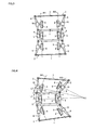
- Figure 1 is a plan view of a self steering truck according to the present invention.
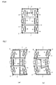
- Figure 2 is a plan view for explaining the motion of the self steering truck shown in Figure 1 at the time of turning a curve.
- a main frame 1 having a rectangular frame shape in a plan view and sub frames 2 provided at the front and rear of the main frame 1 based on the running direction form the base structure of the self steering truck according to the present invention.
- Axles 4 and 4 of right and left drive wheels 3 and 3 are rotatably supported on the main frame 1 via axle boxes 5 and 5.
- the same drive torque is applied to the right and left drive wheels 3 and 3 by use of a series motor or a differential gear.
- a cylindrical tread is employed as the tread shape of the drive wheels 3 and 3.
- a conical or circular tread is preferably employed.
- the sub frame 2 includes right and left swing arms 6 and 6 whose proximal end portions are pivotably supported on the main frame 1 in a horizontal plane, and a coupling link 7 for coupling the distal end portions of the swing arms 6 and 6 together to constitute a link.
- the length of the coupling link 7 is set to be equal to the length between the proximal end portions of the swing arms 6 and 6.
- a parallelogram link is thereby formed between the sub frame 2 and the main frame 1.
- An axle 9 of a steering wheel 8 is rotatably supported on each of the swing arms 6 and 6 via an axle box 10.
- a distance L1 between the drive wheel 3 (the center of the axle 4) and the proximal end portion (a joint portion) of the swing arm 6 is set to be equal to a distance L2 between the steering wheel 8 (the center of the axle 9) and the proximal end portion of the swing arm 6.
- the drive wheel 3 travels on the same arc as the steering wheel 7.
- the setting is suitable for a relatively gentle curve where the radius of curvature of an outer rail R1 and the radius of curvature of an inner rail R2 can be considered equivalent to each other.
- Figure 3 is a plan view of a self steering truck according to another embodiment.
- Figure 4 is a plan view for explaining the motion of the self steering truck shown in Figure 3 at the time of turning a curve.
- the length of the coupling link 7 is set to be larger than the length between the proximal end portions of the swing arms 6 and 6, to thereby form a trapezoidal link, that is, an Ackerman steering mechanism between the sub frame 2 and the main frame 1.
- the Ackerman steering mechanism is a mechanism in which an inner wheel has a smaller radius of rotation than that of an outer wheel during yawing as shown in Figure 4 .
- the structure is thus preferable in a case where the curve has a very small radius of curvature since there is a large difference between the radii of curvature of the outer rail R1 and the inner rail R2.
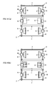
- Figures 5(a) and 5(b) are plan views of a self steering truck according to another embodiment.
- an Ackerman steering link is employed as the structure of the sub frames 2 coupled to the front and rear of the main frame 1, the drive wheels are not provided in the main frame 1.
- Figure 6 is a plan view of a self steering truck according to another embodiment.
- a damper for damping the swing of the sub frame 2 is provided between the main frame 1 and the sub frame 2.
- a direct acting electromagnetic damper 11 or a rotating electromagnetic damper 12 may be employed as well as a normal damper that exerts a hydraulic or air damping force.
- the electromagnetic damper is applied as described above, the swing of the sub frame 2 is not only damped to stabilize the operation, but the swing of the sub frame can be also actively controlled in association with the curve of a track.
- Figures 7(a) and 7(b) are plan views of a self-steering truck according to another embodiment.
- the front end of the left-side swing arm 6 of the front sub frame 2 is coupled to the rear end of the right-side swing arm 6 of the rear sub frame 2 via a link mechanism 13 such that the steering wheel 8 of the front sub frame 2 is in opposite phase to the steering wheel 8 of the rear sub frame 2.
- the left-side swing arm 6 of the front sub frame 2 is formed into an L shape
- the right-side swing arm 6 of the rear sub frame 2 is formed into an L shape.
- a link mechanism 14 couples the L-shaped arms together such that the steering wheels are in opposite phase.
- Figure 8 is a plan view of a self steering truck according to another embodiment.
- the sub frame 2 is provided at only one of the front or rear ends of the main frame 1.
- the configuration is effective in a case where the vehicle is short and only one sub frame can be coupled thereto or in a case of a one-way operation.
- Figure 9 is a plan view of a self steering truck according to another embodiment.
- a single axle 4 is mounted on the main frame 1, and the drive wheels 3 and 3 are mounted on the both ends of the axle 4.
- the structure is disadvantageous to a low floor type, a mechanism for transmitting a drive force can be simplified.
- Figures 10(a) to 10(d) are plan views of a self-steering truck according to another embodiment.
- a flange for preventing derailment is not provided in the drive wheel 3. This is because the front and rear steering wheels have flanges and the drive wheel is thus not required to have a flange.
- the drive wheel 3 is made of rubber, or a rubber layer is formed on the surface of the drive wheel 3.
- the rubber drive wheel 3 is placed on a rail, so that the vehicle runs by a frictional force with the rail.
- the single rubber drive wheel 3 is arranged in the intermediate portion of the main frame 1 in the width direction.
- the vehicle runs by friction not with the rail but with a track surface.
- the rail works only for a steering operation and is thus subject to less wear. Therefore, the rail requires less maintenance.
- the rubber drive wheel 3 is arranged outside the main frame 1.
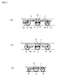
- Figures 11(a) to 11(c) are enlarged side views illustrating an application example to a railway vehicle.
- a bolsterless air spring 15 is arranged between the vehicle and the self steering truck, and a mono link 16, a wing spring 17, or a guide member 18 are used as a method for supporting the axle box.
- the drive wheel may have a larger diameter, and the steering wheels may have smaller diameters while the diameters of the front and rear steering wheels are different from each other as shown in Figure 11(c) .
- the load share ratio of the drive wheel is made largest as shown in the drawings, so that the drive force of the drive wheel can be increased.
- Figures 12(a) to 12(d) are side views illustrating an application example to a railway vehicle.
- the self steering truck according to the present invention is applied to the front and rear of a single vehicle.
- the self steering truck according to the present invention is applied to a coupling portion between two vehicles.
- the self steering truck according to the present invention is applied to each of three coupled vehicles.
- the self steering truck according to the present invention is applied to vehicles on the both ends of three coupled vehicles excluding an intermediate vehicle.
Landscapes
- Engineering & Computer Science (AREA)
- Mechanical Engineering (AREA)
- Steering-Linkage Mechanisms And Four-Wheel Steering (AREA)
- Platform Screen Doors And Railroad Systems (AREA)
Abstract
Description
- The present invention relates to a truck for supporting a railway vehicle, and more particularly, to a self steering truck having excellent sharp turning performance such as a truck for an LRT (light rail transit) vehicle.
- For railway vehicles, turning performance and running stability are required. The turning performance is achieved by a self steering function based on the tread gradient of a wheel. The self steering function can be improved by freeing the yawing of a wheel axle. However, when the yawing of a wheel axle is freed, a self-excited vibration called hunting oscillation occurs, to thereby deteriorate the running stability.
To improve the self steering function, a monocycle independently-rotatable truck in which independently-rotatable wheel units (axle and wheel) are provided on the right and left sides of a bogie frame is preferably employed. Examples of the related art regarding the monocycle independently-rotatable truck includePatent Document 1,Patent Document 2, and Non-PatentDocument 1. -
Patent Document 1 discloses a structure in which axle arms are coupled to the right and left sides of a truck frame having a square U shape respectively via two links, right and left wheels are rotatably supported on the right and left axle arms, and the right and left axle arms are coupled together via a link in the width direction. Also, Non-PatentDocument 1 discloses a basic point regarding the monocycle independently-rotatable truck. - In
Patent Document 2, it is proposed to solve a response delay of a wheel to a curve by arranging a steering assist actuator such as an electromagnetic damper based on the disclosures inPatent Document 1 andNon-Patent Document 1. - Also,
Patent Document 3 proposes a single truck obtained by swingably coupling two truck frames together. In the truck, a front-side truck and a rear-side truck are coupled together through a pin, and a wheel unit where right and left wheels are mounted on a single axle is provided in each of the trucks. -
-
Patent Document 1
Japanese Patent Laid-Open No.2002-302038 -
Patent Document 2
WO 2006/075756 -
Patent Document 3
Japanese Patent Laid-Open No.02-293253 - Non-Patent
Document 1 - Fritz Frederich, Possibilities as yet unknown or unused regarding the wheel/rail tracking mechanism, Development of modem rolling stock running gear, Rail International, November 1985, p33
- None of
Patent Documents Non-Patent Document 1 disclosing the truck clearly describes the relationship between a drive wheel and a steering wheel. Particularly, to allow a vehicle to smoothly run on a track with a very small radius of curvature such as a light rail transit vehicle, it is considered preferable that the drive wheel and the steering wheel be as close as possible to each other. However, there is no disclosure on the point. - Since the truck disclosed in
Patent Document 3 is based on the single axle truck where the right and left wheels are mounted on the single axle, the truck has limited turning performance, and is thus not suitable for the track of LRT or the like with a very small radius of curvature such as a light rail transit vehicle. - To solve the aforementioned problems, in a self steering truck according to the present invention, a single truck includes a main frame and a sub frame, wherein right and left drive wheels are rotatably supported on the main frame, the sub frame includes right and left swing arms whose proximal end portions are supported on the main frame in a swingable manner in a yawing direction and a link for coupling the arms, and independently-rotatable steering wheels having a self steering function are provided on the right and left swing arms.
- Although the sub frame may be provided at only one of the front and rear of the main frame, it is preferable to provide the sub frame at each of the front and rear of the main frame in view of stability. When the sub frames are provided at both the front and rear of the main frame, the front and rear sub frames are coupled together via a link mechanism such that the steering wheels mounted on the front and rear sub frames are in opposite phase. Accordingly, the stability is improved and a higher response to a small radius of curvature is obtained.
- A basic shape of a link formed by one side of the main frame and the sub frame is a parallelogram where the length of the coupling link that constitutes the sub frame is equal to the length between the proximal end portions of the right and left swing arms. However, when the length of the coupling link is made larger than the length between the proximal end portions of the right and left swing arms, the radius of rotation of an inner wheel can be made smaller than the radius of rotation of an outer wheel during yawing. That is, an Ackerman steering mechanism can be formed. The Ackerman steering mechanism is a preferable structure for a curve with a very small radius of curvature.
- A damper for damping the swing of the sub frame, or an electromagnetic damper also having a function of actively controlling the swing of the sub frame may be provided between the main frame and the sub frame.
- According to the present invention, the drive wheels and the steering wheels are provided in the single truck, and the steering wheels are mounted on the sub frame that is swingable relative to the main frame on which the drive wheels are mounted. Accordingly, the self steering truck having excellent turning performance can be obtained.
Particularly, by employing a monocycle independent type wheel for all the wheels including the drive wheels, no axle is extended over the width direction of a vehicle. Thus, the self steering truck is also preferable for a low floor type vehicle. -
-
Figure 1 is a plan view of a self steering truck according to the present invention; -
Figure 2 is a plan view for explaining the motion of the self steering truck shown inFigure 1 at the time of turning a curve; -
Figure 3 is a plan view of a self steering truck according to another embodiment; -
Figure 4 is a plan view for explaining the motion of the self steering truck shown inFigure 3 at the time of turning a curve; -
Figures 5(a) and 5(b) are plan views of a self steering truck according to another embodiment; -
Figure 6 is a plan view of a self steering truck according to another embodiment; -
Figures 7(a) and 7(b) are plan views of a self steering truck according to another embodiment; -
Figure 8 is a plan view of a self steering truck according to another embodiment; -
Figure 9 is a plan view of a self steering truck according to another embodiment; -
Figures 10(a) and 10(b) are plan views of a self steering truck according to another embodiment; -
Figures 10(c) and 10(d) are plan views of a self steering truck according to another embodiment; -
Figures 11(a) to 11(c) are enlarged side views illustrating an application example to a railway vehicle; and -
Figures 12(a) to 12(d) are side views illustrating an application example to a railway vehicle. -
- 1:
- Main frame
- 2:
- Sub frame
- 3:
- Drive wheel
- 4:
- Axle
- 5:
- Axle box
- 6:
- Swing arm
- 7:
- Coupling link
- 8:
- Steering wheel
- 9:
- Axle
- 10:
- Axle box
- 11:
- Direct acting damper
- 12:
- Rotating damper
- 13, 14:
- Link mechanism
- 15:
- Bolsterless air spring
- 16:
- Mono link
- 17:
- Wing spring
- 18:
- Guide member
- L1:
- Distance between a drive wheel and the proximal end portion of a swing arm
- L2:
- Distance between a steering wheel and the proximal end portion of a swing arm
- R1:
- Outer rail
- R2:
- Inner rail
- In the following, a best mode for carrying out the present invention will be described in detail with reference to the drawings.
Figure 1 is a plan view of a self steering truck according to the present invention.Figure 2 is a plan view for explaining the motion of the self steering truck shown inFigure 1 at the time of turning a curve. - A
main frame 1 having a rectangular frame shape in a plan view andsub frames 2 provided at the front and rear of themain frame 1 based on the running direction form the base structure of the self steering truck according to the present invention. -
Axles drive wheels main frame 1 viaaxle boxes drive wheels
In a case of using the independent wheels as shown in the drawings or in a case of using wheels with no flange described below, a cylindrical tread is employed as the tread shape of thedrive wheels - The
sub frame 2 includes right and leftswing arms main frame 1 in a horizontal plane, and acoupling link 7 for coupling the distal end portions of theswing arms coupling link 7 is set to be equal to the length between the proximal end portions of theswing arms sub frame 2 and themain frame 1. - An
axle 9 of asteering wheel 8 is rotatably supported on each of theswing arms axle box 10. A distance L1 between the drive wheel 3 (the center of the axle 4) and the proximal end portion (a joint portion) of theswing arm 6 is set to be equal to a distance L2 between the steering wheel 8 (the center of the axle 9) and the proximal end portion of theswing arm 6. - With the aforementioned configuration, when a vehicle passes through a curved rail track, the
swing arm 6 swings along the curve of the rail track, and a steering angle is generated in thesteering wheel 8 as shown inFigure 2 . Accordingly, the vehicle can smoothly yaw with substantially no angle of attack. - Also, since the distance L1 is equal to the distance L2 in the parallelogram link, the
drive wheel 3 travels on the same arc as thesteering wheel 7. The setting is suitable for a relatively gentle curve where the radius of curvature of an outer rail R1 and the radius of curvature of an inner rail R2 can be considered equivalent to each other. -
Figure 3 is a plan view of a self steering truck according to another embodiment.Figure 4 is a plan view for explaining the motion of the self steering truck shown inFigure 3 at the time of turning a curve. In the embodiment, the length of thecoupling link 7 is set to be larger than the length between the proximal end portions of theswing arms sub frame 2 and themain frame 1. - The Ackerman steering mechanism is a mechanism in which an inner wheel has a smaller radius of rotation than that of an outer wheel during yawing as shown in
Figure 4 . The structure is thus preferable in a case where the curve has a very small radius of curvature since there is a large difference between the radii of curvature of the outer rail R1 and the inner rail R2. -
Figures 5(a) and 5(b) are plan views of a self steering truck according to another embodiment. In the embodiment, while an Ackerman steering link is employed as the structure of the sub frames 2 coupled to the front and rear of themain frame 1, the drive wheels are not provided in themain frame 1. -
Figure 6 is a plan view of a self steering truck according to another embodiment. In the embodiment, a damper for damping the swing of thesub frame 2 is provided between themain frame 1 and thesub frame 2. As the damper, a direct actingelectromagnetic damper 11 or a rotatingelectromagnetic damper 12 may be employed as well as a normal damper that exerts a hydraulic or air damping force. When the electromagnetic damper is applied as described above, the swing of thesub frame 2 is not only damped to stabilize the operation, but the swing of the sub frame can be also actively controlled in association with the curve of a track. -
Figures 7(a) and 7(b) are plan views of a self-steering truck according to another embodiment. In the embodiment shown inFigure 7(a) , the front end of the left-side swing arm 6 of thefront sub frame 2 is coupled to the rear end of the right-side swing arm 6 of therear sub frame 2 via alink mechanism 13 such that thesteering wheel 8 of thefront sub frame 2 is in opposite phase to thesteering wheel 8 of therear sub frame 2. Similarly, inFigure 7(b) , the left-side swing arm 6 of thefront sub frame 2 is formed into an L shape, and the right-side swing arm 6 of therear sub frame 2 is formed into an L shape. Alink mechanism 14 couples the L-shaped arms together such that the steering wheels are in opposite phase. By allowing the front and rear steering wheels to be in opposite phase as described above, the vehicle can smoothly run along a curve with a very small radius of curvature. -
Figure 8 is a plan view of a self steering truck according to another embodiment. In the embodiment, thesub frame 2 is provided at only one of the front or rear ends of themain frame 1. The configuration is effective in a case where the vehicle is short and only one sub frame can be coupled thereto or in a case of a one-way operation. -
Figure 9 is a plan view of a self steering truck according to another embodiment. In the embodiment, asingle axle 4 is mounted on themain frame 1, and thedrive wheels axle 4. Although the structure is disadvantageous to a low floor type, a mechanism for transmitting a drive force can be simplified. -
Figures 10(a) to 10(d) are plan views of a self-steering truck according to another embodiment. In the embodiment shown inFigure 10(a) , a flange for preventing derailment is not provided in thedrive wheel 3. This is because the front and rear steering wheels have flanges and the drive wheel is thus not required to have a flange.
In the embodiment shown inFigures 10(b) to 10(d) , thedrive wheel 3 is made of rubber, or a rubber layer is formed on the surface of thedrive wheel 3. In a type shown inFigure 10(b) , therubber drive wheel 3 is placed on a rail, so that the vehicle runs by a frictional force with the rail. Even when thedrive wheel 3 is in contact with the rail as described above, a load applied to the rail can be considerably reduced and the drive force can be increased by employing therubber drive wheel 3.
In a type shown inFigure 10(c) , the singlerubber drive wheel 3 is arranged in the intermediate portion of themain frame 1 in the width direction. In the type, the vehicle runs by friction not with the rail but with a track surface. Thus, it is necessary to make the surface between the outer rail and the inner rail flat with asphalt or concrete. In the type, the rail works only for a steering operation and is thus subject to less wear. Therefore, the rail requires less maintenance.
In a type shown inFigure 10(d) , therubber drive wheel 3 is arranged outside themain frame 1. In the truck according to the type, a smaller load is applied to the rail as in the aforementioned type. Also, since thedrive wheels 3 project to the right and left, the running stability is improved regardless of running on a straight track or a curved track. The configuration is effective especially when the vehicle has a narrow gauge. -
Figures 11(a) to 11(c) are enlarged side views illustrating an application example to a railway vehicle. In types shown inFigures 11(a) and 11(b) , abolsterless air spring 15 is arranged between the vehicle and the self steering truck, and amono link 16, awing spring 17, or aguide member 18 are used as a method for supporting the axle box. The drive wheel may have a larger diameter, and the steering wheels may have smaller diameters while the diameters of the front and rear steering wheels are different from each other as shown inFigure 11(c) .
The load share ratio of the drive wheel is made largest as shown in the drawings, so that the drive force of the drive wheel can be increased. -
Figures 12(a) to 12(d) are side views illustrating an application example to a railway vehicle. In a type shown inFigure 12(a) , the self steering truck according to the present invention is applied to the front and rear of a single vehicle. In a type shown inFigure 12(b) , the self steering truck according to the present invention is applied to a coupling portion between two vehicles. In a type shown inFigure 12(c) , the self steering truck according to the present invention is applied to each of three coupled vehicles. In a type shown inFigure 12(d) , the self steering truck according to the present invention is applied to vehicles on the both ends of three coupled vehicles excluding an intermediate vehicle.
Claims (8)
- A self steering truck for supporting a railway vehicle, the truck comprising a main frame and a sub frame, wherein right and left drive wheels are rotatably supported on the main frame, the sub frame comprises right and left swing arms whose proximal end portions are supported on the main frame in a swingable manner in a yawing direction and a link for coupling the arms, and independently-rotatable steering wheels having a self steering function are provided on the right and left swing arms.
- A self steering truck for supporting a railway vehicle, the truck comprising a main frame and a sub frame, wherein a rubber drive wheel is rotatably supported on the main frame, the sub frame comprises right and left swing arms whose proximal end portions are supported on the main frame in a swingable manner in a yawing direction and a link for coupling the arms, and independently-rotatable steering wheels having a self steering function are provided on the right and left swing arms.
- The self steering truck according to claim 1 or 2, wherein the sub frame is provided at each of a front and a rear of the main frame.
- The self steering truck according to claim 3, wherein the front and rear sub frames are coupled together via a link mechanism such that the steering wheels mounted on the front and rear sub frames are in opposite phase.
- The self steering truck according to claim 1 or 2, wherein a length of the coupling link that constitutes the sub frame is equal to a length between the proximal end portions of the right and left swing arms to thereby form a parallelogram link.
- The self steering truck according to claim 1 or 2, wherein a distance (L1) between a center of an axle of the drive wheel and the proximal end portion of the swing arm is set to be equal to a distance (L2) between a center of an axle of the steering wheel and the proximal end portion of the swing arm.
- The self steering truck according to claim 1 or 2, wherein a length of the coupling link that constitutes the sub frame is larger than a length between the proximal end portions of the right and left swing arms to thereby form an Ackerman steering mechanism.
- The self steering truck according to any one of claims 1 to 7, wherein a damper for damping swing of the sub frame, or an electromagnetic damper also having a function of actively controlling the swing of the sub frame is provided between the main frame and the sub frame.
Applications Claiming Priority (2)
| Application Number | Priority Date | Filing Date | Title |
|---|---|---|---|
| JP2007196987 | 2007-07-30 | ||
| PCT/JP2008/063577 WO2009017114A1 (en) | 2007-07-30 | 2008-07-29 | Self-steering platform car |
Publications (3)
| Publication Number | Publication Date |
|---|---|
| EP2184214A1 true EP2184214A1 (en) | 2010-05-12 |
| EP2184214A4 EP2184214A4 (en) | 2013-01-02 |
| EP2184214B1 EP2184214B1 (en) | 2017-04-05 |
Family
ID=40304344
Family Applications (1)
| Application Number | Title | Priority Date | Filing Date |
|---|---|---|---|
| EP08791812.4A Not-in-force EP2184214B1 (en) | 2007-07-30 | 2008-07-29 | Self-steering platform car |
Country Status (3)
| Country | Link |
|---|---|
| EP (1) | EP2184214B1 (en) |
| JP (1) | JP5311414B2 (en) |
| WO (1) | WO2009017114A1 (en) |
Cited By (3)
| Publication number | Priority date | Publication date | Assignee | Title |
|---|---|---|---|---|
| KR101329001B1 (en) | 2011-12-20 | 2013-11-12 | 한국철도기술연구원 | Independence rotating wheels suspension apparatus for low-floor vehicle |
| RU2562659C1 (en) * | 2014-03-18 | 2015-09-10 | Федеральное государственное бюджетное образовательное учреждение высшего профессионального образования "Елецкий государственный университет им. И.А. Бунина" | Diesel locomotive three axle bogie |
| IT202200004646A1 (en) * | 2022-03-10 | 2023-09-10 | Aar Ingegneria Di Ferrario Roberto & C S A S | IMPROVED RAILWAY TROLLEY AND RAILWAY VEHICLE EQUIPPED WITH SUCH TROLLEY |
Families Citing this family (3)
| Publication number | Priority date | Publication date | Assignee | Title |
|---|---|---|---|---|
| KR101772606B1 (en) * | 2015-11-05 | 2017-08-31 | 한국철도기술연구원 | 3 axle bogie for railway car |
| JP6624293B2 (en) * | 2016-07-29 | 2019-12-25 | 日本製鉄株式会社 | Truck for railway vehicle and railway vehicle equipped with the truck |
| WO2026139840A1 (en) * | 2024-12-25 | 2026-07-02 | 박경식 | Multi-axle bogie using cylindrical wheels |
Family Cites Families (13)
| Publication number | Priority date | Publication date | Assignee | Title |
|---|---|---|---|---|
| FR719436A (en) * | 1931-07-02 | 1932-02-05 | Bogie for rail vehicles | |
| US3066617A (en) * | 1960-03-24 | 1962-12-04 | Sidney H Bingham | Light weight rapid transit truck |
| ZA727978B (en) * | 1972-11-10 | 1974-07-31 | Inventions Dev Corp Sa | Improvements in railway suspensions |
| JPS59230859A (en) * | 1983-06-15 | 1984-12-25 | 株式会社日立製作所 | Truck for railway rolling stock |
| JPS62285604A (en) * | 1986-06-03 | 1987-12-11 | H S S T:Kk | Flexible type bogie structure of linear motor car |
| BE1001811A3 (en) * | 1988-06-22 | 1990-03-13 | Ferroviaires & Metall Constr | Joint guidance and device for a rail vehicle lift. |
| JPH02293253A (en) | 1989-05-08 | 1990-12-04 | Hitachi Ltd | Steering system for radial truck |
| GB2280160B (en) * | 1993-07-14 | 1998-04-29 | Tram Research Limited | Railway rolling stock |
| EP0658465B1 (en) * | 1993-12-15 | 1998-02-25 | ABB Daimler-Benz Transportation (Technology) GmbH | Self steering three axle bogie for a railway vehicle |
| JP3471157B2 (en) * | 1996-02-27 | 2003-11-25 | 東芝トランスポートエンジニアリング株式会社 | 3-axis steering bogie for railway vehicles |
| JP3524511B2 (en) * | 2001-01-31 | 2004-05-10 | 川崎重工業株式会社 | Single-axle bogies for railway vehicles |
| JP4562655B2 (en) * | 2003-07-16 | 2010-10-13 | 財団法人生産技術研究奨励会 | Self-steering cart and railway vehicle to which the self-steering cart is applied |
| WO2006075756A1 (en) * | 2005-01-17 | 2006-07-20 | The University Of Tokyo | Self-steering bogie |
-
2008
- 2008-07-29 EP EP08791812.4A patent/EP2184214B1/en not_active Not-in-force
- 2008-07-29 WO PCT/JP2008/063577 patent/WO2009017114A1/en not_active Ceased
- 2008-07-29 JP JP2009525405A patent/JP5311414B2/en not_active Expired - Fee Related
Cited By (4)
| Publication number | Priority date | Publication date | Assignee | Title |
|---|---|---|---|---|
| KR101329001B1 (en) | 2011-12-20 | 2013-11-12 | 한국철도기술연구원 | Independence rotating wheels suspension apparatus for low-floor vehicle |
| RU2562659C1 (en) * | 2014-03-18 | 2015-09-10 | Федеральное государственное бюджетное образовательное учреждение высшего профессионального образования "Елецкий государственный университет им. И.А. Бунина" | Diesel locomotive three axle bogie |
| IT202200004646A1 (en) * | 2022-03-10 | 2023-09-10 | Aar Ingegneria Di Ferrario Roberto & C S A S | IMPROVED RAILWAY TROLLEY AND RAILWAY VEHICLE EQUIPPED WITH SUCH TROLLEY |
| EP4242085A1 (en) * | 2022-03-10 | 2023-09-13 | AAR Ingegneria di Ferrario Roberto & C. S.a.s. | Improved railway bogie and railway vehicle equipped with such bogie |
Also Published As
| Publication number | Publication date |
|---|---|
| JP5311414B2 (en) | 2013-10-09 |
| JPWO2009017114A1 (en) | 2010-10-21 |
| EP2184214A4 (en) | 2013-01-02 |
| WO2009017114A1 (en) | 2009-02-05 |
| EP2184214B1 (en) | 2017-04-05 |
Similar Documents
| Publication | Publication Date | Title |
|---|---|---|
| KR101297938B1 (en) | Bogie for track-guided vehicle | |
| EP2086812B1 (en) | Active steering bogie for railway vehicles using leverage | |
| US10065663B2 (en) | Steering bogie and vehicle | |
| CN102066180A (en) | A monorail bogie with improved roll behavior | |
| EP2184214B1 (en) | Self-steering platform car | |
| US6745700B2 (en) | Radial bogie with steering beam mount unitized brake | |
| JP4979374B2 (en) | Cart for low-floor railway vehicles | |
| CN110949440B (en) | Straddle type monorail traction mechanism with auxiliary steering device and its bogie | |
| KR20140026621A (en) | Railway vehicle steering truck | |
| JP5051771B2 (en) | Wheel unit, bogie, railway vehicle and railway system | |
| JP5765432B2 (en) | Steering method and apparatus for bogie for railway vehicle and bogie | |
| KR101772606B1 (en) | 3 axle bogie for railway car | |
| KR101288526B1 (en) | wheel-axle set steering device for railway vehicle | |
| CN216034392U (en) | A vehicle bogie, vehicle and rail transit system | |
| JP2000264198A (en) | Bogies for monorail vehicles and monorail vehicles | |
| CN112721987B (en) | Straddle type monorail train bogie provided with auxiliary steering device | |
| JP2000505761A (en) | Single-axis running gear with movable independent wheels for articulated vehicle transport wagons | |
| JP3188939B2 (en) | Guide track type vehicle bogie | |
| JP5267857B2 (en) | Three-axle steering carriage for railway vehicles and railway vehicles | |
| KR101040375B1 (en) | Section 3 Steering Bogie for Railroad Vehicles Using Link Method | |
| JP2001001896A (en) | Uniaxial independent wheel bogie for railway vehicles | |
| JP4690712B2 (en) | vehicle | |
| JPS61241259A (en) | Steering truck | |
| CN111483490A (en) | Bogie, rail vehicle and rail transit system | |
| JP2001114103A (en) | Car end coupling device |
Legal Events
| Date | Code | Title | Description |
|---|---|---|---|
| PUAI | Public reference made under article 153(3) epc to a published international application that has entered the european phase |
Free format text: ORIGINAL CODE: 0009012 |
|
| 17P | Request for examination filed |
Effective date: 20100225 |
|
| AK | Designated contracting states |
Kind code of ref document: A1 Designated state(s): AT BE BG CH CY CZ DE DK EE ES FI FR GB GR HR HU IE IS IT LI LT LU LV MC MT NL NO PL PT RO SE SI SK TR |
|
| AX | Request for extension of the european patent |
Extension state: AL BA MK RS |
|
| DAX | Request for extension of the european patent (deleted) | ||
| A4 | Supplementary search report drawn up and despatched |
Effective date: 20121130 |
|
| RIC1 | Information provided on ipc code assigned before grant |
Ipc: B61D 13/00 20060101ALI20121126BHEP Ipc: B61F 5/40 20060101AFI20121126BHEP Ipc: B61F 3/16 20060101ALI20121126BHEP Ipc: B61F 5/30 20060101ALI20121126BHEP |
|
| GRAP | Despatch of communication of intention to grant a patent |
Free format text: ORIGINAL CODE: EPIDOSNIGR1 |
|
| INTG | Intention to grant announced |
Effective date: 20160819 |
|
| RIN1 | Information on inventor provided before grant (corrected) |
Inventor name: WANG, WENJUN Inventor name: SUDA, YOSHIHIRO |
|
| GRAS | Grant fee paid |
Free format text: ORIGINAL CODE: EPIDOSNIGR3 |
|
| GRAJ | Information related to disapproval of communication of intention to grant by the applicant or resumption of examination proceedings by the epo deleted |
Free format text: ORIGINAL CODE: EPIDOSDIGR1 |
|
| GRAL | Information related to payment of fee for publishing/printing deleted |
Free format text: ORIGINAL CODE: EPIDOSDIGR3 |
|
| INTC | Intention to grant announced (deleted) | ||
| GRAR | Information related to intention to grant a patent recorded |
Free format text: ORIGINAL CODE: EPIDOSNIGR71 |
|
| GRAA | (expected) grant |
Free format text: ORIGINAL CODE: 0009210 |
|
| AK | Designated contracting states |
Kind code of ref document: B1 Designated state(s): AT BE BG CH CY CZ DE DK EE ES FI FR GB GR HR HU IE IS IT LI LT LU LV MC MT NL NO PL PT RO SE SI SK TR |
|
| INTG | Intention to grant announced |
Effective date: 20170224 |
|
| REG | Reference to a national code |
Ref country code: GB Ref legal event code: FG4D |
|
| REG | Reference to a national code |
Ref country code: CH Ref legal event code: EP |
|
| REG | Reference to a national code |
Ref country code: AT Ref legal event code: REF Ref document number: 881512 Country of ref document: AT Kind code of ref document: T Effective date: 20170415 |
|
| REG | Reference to a national code |
Ref country code: IE Ref legal event code: FG4D |
|
| REG | Reference to a national code |
Ref country code: DE Ref legal event code: R096 Ref document number: 602008049624 Country of ref document: DE |
|
| REG | Reference to a national code |
Ref country code: FR Ref legal event code: PLFP Year of fee payment: 10 |
|
| REG | Reference to a national code |
Ref country code: NL Ref legal event code: MP Effective date: 20170405 |
|
| REG | Reference to a national code |
Ref country code: LT Ref legal event code: MG4D |
|
| REG | Reference to a national code |
Ref country code: AT Ref legal event code: MK05 Ref document number: 881512 Country of ref document: AT Kind code of ref document: T Effective date: 20170405 |
|
| PG25 | Lapsed in a contracting state [announced via postgrant information from national office to epo] |
Ref country code: NL Free format text: LAPSE BECAUSE OF FAILURE TO SUBMIT A TRANSLATION OF THE DESCRIPTION OR TO PAY THE FEE WITHIN THE PRESCRIBED TIME-LIMIT Effective date: 20170405 |
|
| PG25 | Lapsed in a contracting state [announced via postgrant information from national office to epo] |
Ref country code: HR Free format text: LAPSE BECAUSE OF FAILURE TO SUBMIT A TRANSLATION OF THE DESCRIPTION OR TO PAY THE FEE WITHIN THE PRESCRIBED TIME-LIMIT Effective date: 20170405 Ref country code: GR Free format text: LAPSE BECAUSE OF FAILURE TO SUBMIT A TRANSLATION OF THE DESCRIPTION OR TO PAY THE FEE WITHIN THE PRESCRIBED TIME-LIMIT Effective date: 20170706 Ref country code: FI Free format text: LAPSE BECAUSE OF FAILURE TO SUBMIT A TRANSLATION OF THE DESCRIPTION OR TO PAY THE FEE WITHIN THE PRESCRIBED TIME-LIMIT Effective date: 20170405 Ref country code: NO Free format text: LAPSE BECAUSE OF FAILURE TO SUBMIT A TRANSLATION OF THE DESCRIPTION OR TO PAY THE FEE WITHIN THE PRESCRIBED TIME-LIMIT Effective date: 20170705 Ref country code: ES Free format text: LAPSE BECAUSE OF FAILURE TO SUBMIT A TRANSLATION OF THE DESCRIPTION OR TO PAY THE FEE WITHIN THE PRESCRIBED TIME-LIMIT Effective date: 20170405 Ref country code: AT Free format text: LAPSE BECAUSE OF FAILURE TO SUBMIT A TRANSLATION OF THE DESCRIPTION OR TO PAY THE FEE WITHIN THE PRESCRIBED TIME-LIMIT Effective date: 20170405 Ref country code: LT Free format text: LAPSE BECAUSE OF FAILURE TO SUBMIT A TRANSLATION OF THE DESCRIPTION OR TO PAY THE FEE WITHIN THE PRESCRIBED TIME-LIMIT Effective date: 20170405 |
|
| PGFP | Annual fee paid to national office [announced via postgrant information from national office to epo] |
Ref country code: FR Payment date: 20170724 Year of fee payment: 10 Ref country code: DE Payment date: 20170721 Year of fee payment: 10 |
|
| PG25 | Lapsed in a contracting state [announced via postgrant information from national office to epo] |
Ref country code: PL Free format text: LAPSE BECAUSE OF FAILURE TO SUBMIT A TRANSLATION OF THE DESCRIPTION OR TO PAY THE FEE WITHIN THE PRESCRIBED TIME-LIMIT Effective date: 20170405 Ref country code: IS Free format text: LAPSE BECAUSE OF FAILURE TO SUBMIT A TRANSLATION OF THE DESCRIPTION OR TO PAY THE FEE WITHIN THE PRESCRIBED TIME-LIMIT Effective date: 20170805 Ref country code: BG Free format text: LAPSE BECAUSE OF FAILURE TO SUBMIT A TRANSLATION OF THE DESCRIPTION OR TO PAY THE FEE WITHIN THE PRESCRIBED TIME-LIMIT Effective date: 20170705 Ref country code: LV Free format text: LAPSE BECAUSE OF FAILURE TO SUBMIT A TRANSLATION OF THE DESCRIPTION OR TO PAY THE FEE WITHIN THE PRESCRIBED TIME-LIMIT Effective date: 20170405 Ref country code: SE Free format text: LAPSE BECAUSE OF FAILURE TO SUBMIT A TRANSLATION OF THE DESCRIPTION OR TO PAY THE FEE WITHIN THE PRESCRIBED TIME-LIMIT Effective date: 20170405 |
|
| REG | Reference to a national code |
Ref country code: DE Ref legal event code: R097 Ref document number: 602008049624 Country of ref document: DE |
|
| PG25 | Lapsed in a contracting state [announced via postgrant information from national office to epo] |
Ref country code: DK Free format text: LAPSE BECAUSE OF FAILURE TO SUBMIT A TRANSLATION OF THE DESCRIPTION OR TO PAY THE FEE WITHIN THE PRESCRIBED TIME-LIMIT Effective date: 20170405 Ref country code: RO Free format text: LAPSE BECAUSE OF FAILURE TO SUBMIT A TRANSLATION OF THE DESCRIPTION OR TO PAY THE FEE WITHIN THE PRESCRIBED TIME-LIMIT Effective date: 20170405 Ref country code: EE Free format text: LAPSE BECAUSE OF FAILURE TO SUBMIT A TRANSLATION OF THE DESCRIPTION OR TO PAY THE FEE WITHIN THE PRESCRIBED TIME-LIMIT Effective date: 20170405 Ref country code: CZ Free format text: LAPSE BECAUSE OF FAILURE TO SUBMIT A TRANSLATION OF THE DESCRIPTION OR TO PAY THE FEE WITHIN THE PRESCRIBED TIME-LIMIT Effective date: 20170405 Ref country code: SK Free format text: LAPSE BECAUSE OF FAILURE TO SUBMIT A TRANSLATION OF THE DESCRIPTION OR TO PAY THE FEE WITHIN THE PRESCRIBED TIME-LIMIT Effective date: 20170405 |
|
| PLBE | No opposition filed within time limit |
Free format text: ORIGINAL CODE: 0009261 |
|
| STAA | Information on the status of an ep patent application or granted ep patent |
Free format text: STATUS: NO OPPOSITION FILED WITHIN TIME LIMIT |
|
| PG25 | Lapsed in a contracting state [announced via postgrant information from national office to epo] |
Ref country code: IT Free format text: LAPSE BECAUSE OF FAILURE TO SUBMIT A TRANSLATION OF THE DESCRIPTION OR TO PAY THE FEE WITHIN THE PRESCRIBED TIME-LIMIT Effective date: 20170405 |
|
| REG | Reference to a national code |
Ref country code: CH Ref legal event code: PL |
|
| 26N | No opposition filed |
Effective date: 20180108 |
|
| GBPC | Gb: european patent ceased through non-payment of renewal fee |
Effective date: 20170729 |
|
| PG25 | Lapsed in a contracting state [announced via postgrant information from national office to epo] |
Ref country code: GB Free format text: LAPSE BECAUSE OF NON-PAYMENT OF DUE FEES Effective date: 20170729 Ref country code: CH Free format text: LAPSE BECAUSE OF NON-PAYMENT OF DUE FEES Effective date: 20170731 Ref country code: LI Free format text: LAPSE BECAUSE OF NON-PAYMENT OF DUE FEES Effective date: 20170731 |
|
| REG | Reference to a national code |
Ref country code: IE Ref legal event code: MM4A |
|
| PG25 | Lapsed in a contracting state [announced via postgrant information from national office to epo] |
Ref country code: SI Free format text: LAPSE BECAUSE OF FAILURE TO SUBMIT A TRANSLATION OF THE DESCRIPTION OR TO PAY THE FEE WITHIN THE PRESCRIBED TIME-LIMIT Effective date: 20170405 |
|
| REG | Reference to a national code |
Ref country code: BE Ref legal event code: MM Effective date: 20170731 |
|
| PG25 | Lapsed in a contracting state [announced via postgrant information from national office to epo] |
Ref country code: LU Free format text: LAPSE BECAUSE OF NON-PAYMENT OF DUE FEES Effective date: 20170729 |
|
| PG25 | Lapsed in a contracting state [announced via postgrant information from national office to epo] |
Ref country code: IE Free format text: LAPSE BECAUSE OF NON-PAYMENT OF DUE FEES Effective date: 20170729 |
|
| PG25 | Lapsed in a contracting state [announced via postgrant information from national office to epo] |
Ref country code: BE Free format text: LAPSE BECAUSE OF NON-PAYMENT OF DUE FEES Effective date: 20170731 |
|
| PG25 | Lapsed in a contracting state [announced via postgrant information from national office to epo] |
Ref country code: MT Free format text: LAPSE BECAUSE OF NON-PAYMENT OF DUE FEES Effective date: 20170729 |
|
| REG | Reference to a national code |
Ref country code: DE Ref legal event code: R119 Ref document number: 602008049624 Country of ref document: DE |
|
| PG25 | Lapsed in a contracting state [announced via postgrant information from national office to epo] |
Ref country code: DE Free format text: LAPSE BECAUSE OF NON-PAYMENT OF DUE FEES Effective date: 20190201 Ref country code: FR Free format text: LAPSE BECAUSE OF NON-PAYMENT OF DUE FEES Effective date: 20180731 |
|
| PG25 | Lapsed in a contracting state [announced via postgrant information from national office to epo] |
Ref country code: HU Free format text: LAPSE BECAUSE OF FAILURE TO SUBMIT A TRANSLATION OF THE DESCRIPTION OR TO PAY THE FEE WITHIN THE PRESCRIBED TIME-LIMIT; INVALID AB INITIO Effective date: 20080729 Ref country code: MC Free format text: LAPSE BECAUSE OF FAILURE TO SUBMIT A TRANSLATION OF THE DESCRIPTION OR TO PAY THE FEE WITHIN THE PRESCRIBED TIME-LIMIT Effective date: 20170405 |
|
| PG25 | Lapsed in a contracting state [announced via postgrant information from national office to epo] |
Ref country code: CY Free format text: LAPSE BECAUSE OF NON-PAYMENT OF DUE FEES Effective date: 20170405 |
|
| PG25 | Lapsed in a contracting state [announced via postgrant information from national office to epo] |
Ref country code: TR Free format text: LAPSE BECAUSE OF FAILURE TO SUBMIT A TRANSLATION OF THE DESCRIPTION OR TO PAY THE FEE WITHIN THE PRESCRIBED TIME-LIMIT Effective date: 20170405 |
|
| PG25 | Lapsed in a contracting state [announced via postgrant information from national office to epo] |
Ref country code: PT Free format text: LAPSE BECAUSE OF FAILURE TO SUBMIT A TRANSLATION OF THE DESCRIPTION OR TO PAY THE FEE WITHIN THE PRESCRIBED TIME-LIMIT Effective date: 20170405 |