EP2183898B1 - Mobile television broadcast system - Google Patents
Mobile television broadcast system Download PDFInfo
- Publication number
- EP2183898B1 EP2183898B1 EP08772417.5A EP08772417A EP2183898B1 EP 2183898 B1 EP2183898 B1 EP 2183898B1 EP 08772417 A EP08772417 A EP 08772417A EP 2183898 B1 EP2183898 B1 EP 2183898B1
- Authority
- EP
- European Patent Office
- Prior art keywords
- receiver
- packets
- control information
- stream
- communication
- Prior art date
- Legal status (The legal status is an assumption and is not a legal conclusion. Google has not performed a legal analysis and makes no representation as to the accuracy of the status listed.)
- Active
Links
- 238000004891 communication Methods 0.000 claims description 244
- 238000000034 method Methods 0.000 claims description 218
- 230000005540 biological transmission Effects 0.000 claims description 135
- 238000012986 modification Methods 0.000 claims description 53
- 230000004048 modification Effects 0.000 claims description 53
- 238000012545 processing Methods 0.000 claims description 30
- 230000015654 memory Effects 0.000 claims description 24
- 238000012937 correction Methods 0.000 description 23
- 238000007726 management method Methods 0.000 description 23
- 230000008569 process Effects 0.000 description 20
- 230000008859 change Effects 0.000 description 18
- 238000012549 training Methods 0.000 description 14
- 238000012546 transfer Methods 0.000 description 13
- 230000003190 augmentative effect Effects 0.000 description 11
- 238000001824 photoionisation detection Methods 0.000 description 11
- 230000003068 static effect Effects 0.000 description 11
- 230000009897 systematic effect Effects 0.000 description 11
- 230000007246 mechanism Effects 0.000 description 10
- 230000011664 signaling Effects 0.000 description 10
- 238000004422 calculation algorithm Methods 0.000 description 9
- 238000010586 diagram Methods 0.000 description 9
- 238000001514 detection method Methods 0.000 description 8
- 230000000694 effects Effects 0.000 description 8
- 238000005538 encapsulation Methods 0.000 description 8
- 239000004744 fabric Substances 0.000 description 6
- 230000005641 tunneling Effects 0.000 description 6
- 230000008901 benefit Effects 0.000 description 5
- 230000002452 interceptive effect Effects 0.000 description 5
- 238000013507 mapping Methods 0.000 description 5
- 238000012544 monitoring process Methods 0.000 description 5
- 230000004044 response Effects 0.000 description 5
- 238000009795 derivation Methods 0.000 description 4
- 230000006870 function Effects 0.000 description 4
- PCHJSUWPFVWCPO-UHFFFAOYSA-N gold Chemical compound [Au] PCHJSUWPFVWCPO-UHFFFAOYSA-N 0.000 description 4
- 230000033001 locomotion Effects 0.000 description 4
- 230000001413 cellular effect Effects 0.000 description 3
- 239000000470 constituent Substances 0.000 description 3
- 230000001419 dependent effect Effects 0.000 description 3
- 238000013461 design Methods 0.000 description 3
- 239000000203 mixture Substances 0.000 description 3
- 230000036316 preload Effects 0.000 description 3
- 238000011084 recovery Methods 0.000 description 3
- 239000013589 supplement Substances 0.000 description 3
- 238000012935 Averaging Methods 0.000 description 2
- 230000003466 anti-cipated effect Effects 0.000 description 2
- 238000003491 array Methods 0.000 description 2
- 238000004364 calculation method Methods 0.000 description 2
- 238000006243 chemical reaction Methods 0.000 description 2
- 230000000295 complement effect Effects 0.000 description 2
- 239000006185 dispersion Substances 0.000 description 2
- 238000009826 distribution Methods 0.000 description 2
- 239000000284 extract Substances 0.000 description 2
- 238000001914 filtration Methods 0.000 description 2
- 238000013467 fragmentation Methods 0.000 description 2
- 238000006062 fragmentation reaction Methods 0.000 description 2
- 238000009432 framing Methods 0.000 description 2
- 239000010931 gold Substances 0.000 description 2
- 229910052737 gold Inorganic materials 0.000 description 2
- 239000000463 material Substances 0.000 description 2
- 238000005259 measurement Methods 0.000 description 2
- 239000003607 modifier Substances 0.000 description 2
- 238000000926 separation method Methods 0.000 description 2
- 230000007480 spreading Effects 0.000 description 2
- 238000003892 spreading Methods 0.000 description 2
- 230000001360 synchronised effect Effects 0.000 description 2
- 238000012360 testing method Methods 0.000 description 2
- 230000000007 visual effect Effects 0.000 description 2
- 102100022523 Acetoacetyl-CoA synthetase Human genes 0.000 description 1
- 101000678027 Homo sapiens Acetoacetyl-CoA synthetase Proteins 0.000 description 1
- 235000017848 Rubus fruticosus Nutrition 0.000 description 1
- 244000078534 Vaccinium myrtillus Species 0.000 description 1
- 238000013459 approach Methods 0.000 description 1
- 230000001174 ascending effect Effects 0.000 description 1
- 230000003416 augmentation Effects 0.000 description 1
- 230000006399 behavior Effects 0.000 description 1
- 235000021029 blackberry Nutrition 0.000 description 1
- 239000002131 composite material Substances 0.000 description 1
- 230000006835 compression Effects 0.000 description 1
- 238000007906 compression Methods 0.000 description 1
- 238000011161 development Methods 0.000 description 1
- 238000005516 engineering process Methods 0.000 description 1
- 230000002708 enhancing effect Effects 0.000 description 1
- 238000000605 extraction Methods 0.000 description 1
- 238000005562 fading Methods 0.000 description 1
- 230000008713 feedback mechanism Effects 0.000 description 1
- 239000003292 glue Substances 0.000 description 1
- 230000036039 immunity Effects 0.000 description 1
- 238000003780 insertion Methods 0.000 description 1
- 230000037431 insertion Effects 0.000 description 1
- 238000005304 joining Methods 0.000 description 1
- 239000004973 liquid crystal related substance Substances 0.000 description 1
- 230000014759 maintenance of location Effects 0.000 description 1
- 239000011159 matrix material Substances 0.000 description 1
- 238000002156 mixing Methods 0.000 description 1
- 238000005457 optimization Methods 0.000 description 1
- 230000008520 organization Effects 0.000 description 1
- 238000004806 packaging method and process Methods 0.000 description 1
- 238000012856 packing Methods 0.000 description 1
- 235000013550 pizza Nutrition 0.000 description 1
- 230000035755 proliferation Effects 0.000 description 1
- 230000003252 repetitive effect Effects 0.000 description 1
- 230000003362 replicative effect Effects 0.000 description 1
- 238000009938 salting Methods 0.000 description 1
- 150000003839 salts Chemical class 0.000 description 1
- 230000035945 sensitivity Effects 0.000 description 1
- 238000012163 sequencing technique Methods 0.000 description 1
- 230000002459 sustained effect Effects 0.000 description 1
- 238000013519 translation Methods 0.000 description 1
Images


Classifications
-
- H—ELECTRICITY
- H04—ELECTRIC COMMUNICATION TECHNIQUE
- H04N—PICTORIAL COMMUNICATION, e.g. TELEVISION
- H04N21/00—Selective content distribution, e.g. interactive television or video on demand [VOD]
- H04N21/60—Network structure or processes for video distribution between server and client or between remote clients; Control signalling between clients, server and network components; Transmission of management data between server and client, e.g. sending from server to client commands for recording incoming content stream; Communication details between server and client
- H04N21/63—Control signaling related to video distribution between client, server and network components; Network processes for video distribution between server and clients or between remote clients, e.g. transmitting basic layer and enhancement layers over different transmission paths, setting up a peer-to-peer communication via Internet between remote STB's; Communication protocols; Addressing
- H04N21/643—Communication protocols
- H04N21/6437—Real-time Transport Protocol [RTP]
-
- H—ELECTRICITY
- H03—ELECTRONIC CIRCUITRY
- H03M—CODING; DECODING; CODE CONVERSION IN GENERAL
- H03M13/00—Coding, decoding or code conversion, for error detection or error correction; Coding theory basic assumptions; Coding bounds; Error probability evaluation methods; Channel models; Simulation or testing of codes
- H03M13/29—Coding, decoding or code conversion, for error detection or error correction; Coding theory basic assumptions; Coding bounds; Error probability evaluation methods; Channel models; Simulation or testing of codes combining two or more codes or code structures, e.g. product codes, generalised product codes, concatenated codes, inner and outer codes
- H03M13/2906—Coding, decoding or code conversion, for error detection or error correction; Coding theory basic assumptions; Coding bounds; Error probability evaluation methods; Channel models; Simulation or testing of codes combining two or more codes or code structures, e.g. product codes, generalised product codes, concatenated codes, inner and outer codes using block codes
- H03M13/2909—Product codes
-
- H—ELECTRICITY
- H03—ELECTRONIC CIRCUITRY
- H03M—CODING; DECODING; CODE CONVERSION IN GENERAL
- H03M13/00—Coding, decoding or code conversion, for error detection or error correction; Coding theory basic assumptions; Coding bounds; Error probability evaluation methods; Channel models; Simulation or testing of codes
- H03M13/29—Coding, decoding or code conversion, for error detection or error correction; Coding theory basic assumptions; Coding bounds; Error probability evaluation methods; Channel models; Simulation or testing of codes combining two or more codes or code structures, e.g. product codes, generalised product codes, concatenated codes, inner and outer codes
- H03M13/2957—Turbo codes and decoding
-
- H—ELECTRICITY
- H03—ELECTRONIC CIRCUITRY
- H03M—CODING; DECODING; CODE CONVERSION IN GENERAL
- H03M13/00—Coding, decoding or code conversion, for error detection or error correction; Coding theory basic assumptions; Coding bounds; Error probability evaluation methods; Channel models; Simulation or testing of codes
- H03M13/65—Purpose and implementation aspects
- H03M13/6577—Representation or format of variables, register sizes or word-lengths and quantization
- H03M13/6583—Normalization other than scaling, e.g. by subtraction
-
- H—ELECTRICITY
- H04—ELECTRIC COMMUNICATION TECHNIQUE
- H04L—TRANSMISSION OF DIGITAL INFORMATION, e.g. TELEGRAPHIC COMMUNICATION
- H04L65/00—Network arrangements, protocols or services for supporting real-time applications in data packet communication
- H04L65/60—Network streaming of media packets
- H04L65/61—Network streaming of media packets for supporting one-way streaming services, e.g. Internet radio
- H04L65/611—Network streaming of media packets for supporting one-way streaming services, e.g. Internet radio for multicast or broadcast
-
- H—ELECTRICITY
- H04—ELECTRIC COMMUNICATION TECHNIQUE
- H04L—TRANSMISSION OF DIGITAL INFORMATION, e.g. TELEGRAPHIC COMMUNICATION
- H04L65/00—Network arrangements, protocols or services for supporting real-time applications in data packet communication
- H04L65/60—Network streaming of media packets
- H04L65/70—Media network packetisation
-
- H—ELECTRICITY
- H04—ELECTRIC COMMUNICATION TECHNIQUE
- H04N—PICTORIAL COMMUNICATION, e.g. TELEVISION
- H04N21/00—Selective content distribution, e.g. interactive television or video on demand [VOD]
- H04N21/20—Servers specifically adapted for the distribution of content, e.g. VOD servers; Operations thereof
- H04N21/23—Processing of content or additional data; Elementary server operations; Server middleware
- H04N21/238—Interfacing the downstream path of the transmission network, e.g. adapting the transmission rate of a video stream to network bandwidth; Processing of multiplex streams
- H04N21/2381—Adapting the multiplex stream to a specific network, e.g. an Internet Protocol [IP] network
-
- H—ELECTRICITY
- H04—ELECTRIC COMMUNICATION TECHNIQUE
- H04N—PICTORIAL COMMUNICATION, e.g. TELEVISION
- H04N21/00—Selective content distribution, e.g. interactive television or video on demand [VOD]
- H04N21/20—Servers specifically adapted for the distribution of content, e.g. VOD servers; Operations thereof
- H04N21/23—Processing of content or additional data; Elementary server operations; Server middleware
- H04N21/238—Interfacing the downstream path of the transmission network, e.g. adapting the transmission rate of a video stream to network bandwidth; Processing of multiplex streams
- H04N21/2383—Channel coding or modulation of digital bit-stream, e.g. QPSK modulation
-
- H—ELECTRICITY
- H04—ELECTRIC COMMUNICATION TECHNIQUE
- H04N—PICTORIAL COMMUNICATION, e.g. TELEVISION
- H04N21/00—Selective content distribution, e.g. interactive television or video on demand [VOD]
- H04N21/40—Client devices specifically adapted for the reception of or interaction with content, e.g. set-top-box [STB]; Operations thereof
- H04N21/41—Structure of client; Structure of client peripherals
- H04N21/414—Specialised client platforms, e.g. receiver in car or embedded in a mobile appliance
- H04N21/41407—Specialised client platforms, e.g. receiver in car or embedded in a mobile appliance embedded in a portable device, e.g. video client on a mobile phone, PDA, laptop
-
- H—ELECTRICITY
- H04—ELECTRIC COMMUNICATION TECHNIQUE
- H04N—PICTORIAL COMMUNICATION, e.g. TELEVISION
- H04N21/00—Selective content distribution, e.g. interactive television or video on demand [VOD]
- H04N21/40—Client devices specifically adapted for the reception of or interaction with content, e.g. set-top-box [STB]; Operations thereof
- H04N21/43—Processing of content or additional data, e.g. demultiplexing additional data from a digital video stream; Elementary client operations, e.g. monitoring of home network or synchronising decoder's clock; Client middleware
- H04N21/438—Interfacing the downstream path of the transmission network originating from a server, e.g. retrieving MPEG packets from an IP network
- H04N21/4381—Recovering the multiplex stream from a specific network, e.g. recovering MPEG packets from ATM cells
-
- H—ELECTRICITY
- H04—ELECTRIC COMMUNICATION TECHNIQUE
- H04N—PICTORIAL COMMUNICATION, e.g. TELEVISION
- H04N21/00—Selective content distribution, e.g. interactive television or video on demand [VOD]
- H04N21/40—Client devices specifically adapted for the reception of or interaction with content, e.g. set-top-box [STB]; Operations thereof
- H04N21/43—Processing of content or additional data, e.g. demultiplexing additional data from a digital video stream; Elementary client operations, e.g. monitoring of home network or synchronising decoder's clock; Client middleware
- H04N21/438—Interfacing the downstream path of the transmission network originating from a server, e.g. retrieving MPEG packets from an IP network
- H04N21/4382—Demodulation or channel decoding, e.g. QPSK demodulation
-
- H—ELECTRICITY
- H04—ELECTRIC COMMUNICATION TECHNIQUE
- H04N—PICTORIAL COMMUNICATION, e.g. TELEVISION
- H04N21/00—Selective content distribution, e.g. interactive television or video on demand [VOD]
- H04N21/60—Network structure or processes for video distribution between server and client or between remote clients; Control signalling between clients, server and network components; Transmission of management data between server and client, e.g. sending from server to client commands for recording incoming content stream; Communication details between server and client
- H04N21/61—Network physical structure; Signal processing
- H04N21/6106—Network physical structure; Signal processing specially adapted to the downstream path of the transmission network
- H04N21/6131—Network physical structure; Signal processing specially adapted to the downstream path of the transmission network involving transmission via a mobile phone network
-
- H—ELECTRICITY
- H03—ELECTRONIC CIRCUITRY
- H03M—CODING; DECODING; CODE CONVERSION IN GENERAL
- H03M13/00—Coding, decoding or code conversion, for error detection or error correction; Coding theory basic assumptions; Coding bounds; Error probability evaluation methods; Channel models; Simulation or testing of codes
- H03M13/03—Error detection or forward error correction by redundancy in data representation, i.e. code words containing more digits than the source words
- H03M13/05—Error detection or forward error correction by redundancy in data representation, i.e. code words containing more digits than the source words using block codes, i.e. a predetermined number of check bits joined to a predetermined number of information bits
- H03M13/11—Error detection or forward error correction by redundancy in data representation, i.e. code words containing more digits than the source words using block codes, i.e. a predetermined number of check bits joined to a predetermined number of information bits using multiple parity bits
- H03M13/1102—Codes on graphs and decoding on graphs, e.g. low-density parity check [LDPC] codes
-
- H—ELECTRICITY
- H03—ELECTRONIC CIRCUITRY
- H03M—CODING; DECODING; CODE CONVERSION IN GENERAL
- H03M13/00—Coding, decoding or code conversion, for error detection or error correction; Coding theory basic assumptions; Coding bounds; Error probability evaluation methods; Channel models; Simulation or testing of codes
- H03M13/27—Coding, decoding or code conversion, for error detection or error correction; Coding theory basic assumptions; Coding bounds; Error probability evaluation methods; Channel models; Simulation or testing of codes using interleaving techniques
- H03M13/2732—Convolutional interleaver; Interleavers using shift-registers or delay lines like, e.g. Ramsey type interleaver
-
- H—ELECTRICITY
- H03—ELECTRONIC CIRCUITRY
- H03M—CODING; DECODING; CODE CONVERSION IN GENERAL
- H03M13/00—Coding, decoding or code conversion, for error detection or error correction; Coding theory basic assumptions; Coding bounds; Error probability evaluation methods; Channel models; Simulation or testing of codes
- H03M13/29—Coding, decoding or code conversion, for error detection or error correction; Coding theory basic assumptions; Coding bounds; Error probability evaluation methods; Channel models; Simulation or testing of codes combining two or more codes or code structures, e.g. product codes, generalised product codes, concatenated codes, inner and outer codes
- H03M13/2933—Coding, decoding or code conversion, for error detection or error correction; Coding theory basic assumptions; Coding bounds; Error probability evaluation methods; Channel models; Simulation or testing of codes combining two or more codes or code structures, e.g. product codes, generalised product codes, concatenated codes, inner and outer codes using a block and a convolutional code
- H03M13/2936—Coding, decoding or code conversion, for error detection or error correction; Coding theory basic assumptions; Coding bounds; Error probability evaluation methods; Channel models; Simulation or testing of codes combining two or more codes or code structures, e.g. product codes, generalised product codes, concatenated codes, inner and outer codes using a block and a convolutional code comprising an outer Reed-Solomon code and an inner convolutional code
Definitions
- the present invention relates to the design of a robust mobile television broadcast system, and more specifically in one embodiment relates to the enhancement of the current 8-VSB-based ATSC Digital TV (DTV) broadcast system for mobile services to mobile and handheld devices.
- DTV Digital TV
- the ATSC (Advanced Television Systems Committee) standard relates to a digital television format which will replace the analog NTSC television system.
- the ATSC standard is a high definition television standard that produces standard 4:3 or wide screen 16:9 images up to 1920 ⁇ 1080 pixels in size - more than six times the display resolution of the earlier NTSC standard.
- the ATSC standard makes provisions to transport multiple standard-definition "virtual channels" broadcast on a single 6 MHz TV channel.
- the ATSC standard also includes "theater quality" audio using the Dolby Digital AC-3 format to provide 5.1-channel surround sound.
- the ATSC standard also provides numerous auxiliary datacasting services.
- the ATSC standard uses the MPEG-2 systems specification for encapsulation (transport) of data. More specifically, ATSC uses the 188-byte MPEG transport stream packets to carry data. MPEG-2 is also referred to as "transport stream", “MPEG-TS”, or simply "TS”.
- transport stream MPEG-TS
- TS Transport stream
- the receiver demodulates and applies error correction to the signal. Then, the transport stream may be demultiplexed into its constituent streams.
- a video codec e.g. MPEG-2, H.264, VC-1, is used for encoding and decoding video, subject to certain constraints.
- WO 2006/010373 A1 describes a video-communication service in which a separation in different components of the video-communication is caused at the telephone equipment of the users (e.g. a separation in a video and in a voice component).
- the different components are transmitted on different connections between the telephone equipment of the users.
- the users have the possibility of selectively dropping anyone of the different connections.
- the present invention provides a solution according to the subject matter of the independent claims.
- Embodiments of the invention relate to an improved system and method for transmission and/or reception of audiovisual information, e.g., digital television signals, for improved reception, and in particular to improved mobile reception.
- a digital television broadcast system which comprises a transmission system and one or more devices, e.g., mobile devices.
- Each of the mobile devices may include a display for presenting video information and one or more speakers for presenting audio information.
- each of the mobile devices may include television-like capabilities for presenting received television channels as described herein.
- the digital television broadcast system may also of course include stationary devices.
- the transmission system is configured to transmit audiovisual information (e.g., television signals / channels) to the mobile devices in a wireless manner.
- the mobile devices 112 may receive and present the audiovisual information, e.g., receive and present the digital television signals / channels.
- the transmission system may also be configured to transmit audiovisual information (e.g., television signals / channels) to stationary devices (stationary televisions) in a wireless manner.
- the transmission system comprises a transmitter as well as transmit logic.
- the transmit logic is adapted for receiving and/or storing audiovisual information (e.g., television data) and for generating packets containing the audiovisual information.
- the transmit logic may generate packets according to the ATSC (Advanced Television Standards Committee) standard, e.g., using 8-VSB modulation.
- ATSC Advanced Television Standards Committee
- one or more of the digital television channels are intended for stationary receivers, such as televisions.
- One or more of the digital television channels are also intended for mobile and/or handheld (M/H) (referred to collectively herein as "mobile”) devices.
- M/H mobile and/or handheld
- the transmission system receives (or generates) instructions to modify the system (transmission / receive) configuration.
- the transmission system determines channel characteristics of the wireless communication medium and then determines a modification to the system (transmission / receive) configuration based on the current channel characteristics.
- the transmission system may be configured to modify its own configuration, e.g., by modifying parameter values in one or more communication layers in the transmission system.
- the transmission system may correspondingly also generate control information to dynamically configure corresponding communication layers in the receivers of various mobile devices.
- the modification to the configuration of the transmission / receive system may comprise modifications to various operational characteristics of the transmission system / receiver, such as video codec used, audio codec used, image resolution, the amount and/or type of forward error correction, receive parameters, multiplexing arrangement, etc.
- the transmission / receive system may thus be modified to dynamically configure the system based on the channel characteristics of the wireless communication medium and/or based on received instructions.
- the transmission system may examine current parameters of a plurality of the communication layers and determine the system modifications (modifications to the transmit and receive logic) based on these parameters.
- the system modifications may comprise modifying a first communication layer in the transmit/receive system, or a plurality of the communication layers.
- the transmission system may examine parameters of various of the communication layers and determine modifications to other parameters in the first communication layer and/or modifications to parameters in other communication layers.
- the transmission system is configured to adjust one or more of a plurality of the "communication layers" in the transmission system / receiver, including the Physical layer as well as the higher layers, such as the Management layer and Presentation layer.
- the modifications may include modifying a plurality of the communication layers, e.g., two or more of the communication layers.
- the communication layer modifications may be generated based on parameter values of a plurality of the communication layers, or may be generated to improve or optimize operation across the plurality of communication layers. The methods thus provide for "cross layer control" as described herein.
- the transmission system generates and transmits packets to the receiver over the communication medium, the packets containing audiovisual information as well as control information.
- the packets containing audiovisual information may comprise one or more digital television channels intended for devices, including mobile devices.
- the transmission system generates packets according to the ATSC (Advanced Television Standards Committee) DTV (digital television) standard containing one or more digital television channels intended for stationary receivers (e.g., televisions), and generates packets containing one or more digital television channels intended for mobile/handheld (M/H) receivers.
- Generation of the packets containing audiovisual information may comprise various steps, such as encoding the audio and video data (e.g., using MPEG-2 encoding), applying forward error correction, generating appropriate packet headers and control information, etc.
- the control information may be comprised in packets that use an otherwise unassigned packet ID (uPID).
- the control information may be useable to dynamically reconfigure operation of the mobile devices, e.g., dynamically configure communication layers operating in the mobile devices.
- the control information may be configured to dynamically configure operation of the mobile devices based on changes made in the transmission system.
- the control information may utilize a command structure that is known both on the transmit side and the receive side.
- the command structure may be organized as a hierarchical tree.
- the commands comprised in the control information may be configured to modify parameters stored according to a hierarchical tree structure in the receiver, wherein the hierarchical tree structure represents the receiver (and transmission system) configuration. This hierarchical tree structure is discussed in greater detail below.
- the hierarchical tree structure may also allow for new nodes to be added to the tree after deployment of transmission and receiver systems, where the new nodes add new functionality in the system.
- the transmit method may generate the control information configured to modify the hierarchical tree structure in the receiver to provide extended (new or modified) functionality in the receiver.
- the transmission method may also operate to transmit version information or some other characteristic of the services, where the version information or other characteristic can be used to group control information into subgroups of services supported by various generations of radios.
- the transmission method may further include descriptors or modifiers that can be applied across sets of nodes to more efficiently specify parameter values in the tree.
- the transmission method may also include a table describing the services offered by version or by some other parameter(s), coupled with an offset into the control information or some other method of vectoring to the location in the control information where the control stream that supports the listed service is located.
- the transmission system provides information to the receiver to configure the receiver regarding how to receive the packets, e.g., the ordering of the packets in the transmitted data stream. Once the packet ordering is established, the method may subsequently only send delta information to the receiver regarding changes in the ordering of transmitted packets.
- transmission of the packets may comprise transmitting a first plurality of packets comprising audiovisual information intended for mobile devices (first stream), a second plurality of packets comprising control information (second stream), and a third plurality of packets comprising standard digital television signals intended for stationary televisions (third stream).
- the standard digital television signals may not be useable by the mobile device.
- the standard digital television signals may be received, processed and presented by the mobile device(s).
- Transmission of these plurality of packets may comprise multiplexing the first, second, and third plurality of packets (multiplexing the first, second and third streams). Multiplexing of these different packets or streams may be performed in a systematic way based on a ratio of the relative bandwidth allocations of the respective pluralities of packets (or streams).
- multiplexing these different packet streams comprises ordering the packets to distribute them evenly according to their relative bandwidth. This method will be referred to as continuous mode.
- burst mode the packet content associated with each stream (first, second and third) is sent in aggregated bursts where the start of each burst is indicated as part of the control information.
- the multiplexing may operate to reduce transmission overhead.
- the transmission method transmits size information regarding the bandwidth allocations of the various packet streams, wherein the size information is useable at the receiver to derive the systematic multiplexing arrangement employed by the receiver and in accordance with the multiplexing arrangement demultiplex the received packet streams.
- the receiver may use the knowledge of the size information to "know" how to properly demultiplex the received packets. This concept of systematic multiplexing can be applied to both the continuous and burst mode cases.
- Mobile devices are configured to receive the packets transmitted by the transmission system, including the packets containing audiovisual information and the packets containing control information.
- the receiver then operates to demultiplex the received packets in a systematic manner complementary to that employed by the transmitter in multiplexing the packet streams, e.g., based on received size information as mentioned above.
- the receiver in the mobile device e.g., each mobile device
- the receiver in the mobile device is then configured based on the received commands contained in the control information.
- the mobile device extracts commands from the received packets and configures its operation according to these commands.
- the commands contained in the control information may be executed to modify operation of one or more communication layers in the receiver (e.g., to match the communication layer changes made in the transmission system).
- a respective mobile device is configured to use the control information to configure its operation during reception and/or presentation of the received audiovisual information.
- the receiver in the mobile device is configured according to the indicated video codec and/or audio codec.
- the control information specifies use of a certain amount of forward error correction
- the receiver in the mobile device is configured to decode received data based on the amount of indicated forward error correction.
- the control information specifies use of a certain display resolution
- the receiver is modified to produce the indicated display resolution.
- the receiver in the mobile device processes packets containing audiovisual information based on its configuration.
- the receiver processes subsequently received packets according to the changes made to the one or more communication layers.
- the various communication layers in the receiver operate to process audiovisual data in subsequently received packets.
- the mobile device then presents audiovisual information on its display based upon the received and processed packets.
- the mobile device may operate according to its configuration (per the received control information) to process the received information and present the received audiovisual information on its display.
- the receiver in the mobile device transmits feedback information back to the transmission system.
- the receiver in the mobile device may transmit the feedback information back to the transmission system over any of various mediums, e.g., a return path, such as a cellular network or WAN/WAP, etc.
- the feedback information may comprise various types of information, such as packet error rates, packet loss information, receiver capabilities, user settings, etc.
- the transmission system may then use this feedback information in determining how to adjust the broadcast system, e.g., which parameters to adjust in one or more of the communication layers in the transmission / receive systems.
- the receiver in the mobile device may also transmit control information to the transmission system to configure the transmission system.
- the receiver obtain various information, such as packet error rates, user input, etc., and may reconfigure itself (by changing one or more parameters in one or more communication layers in the receiver).
- the receiver may then generate control information (in a similar manner in which the transmission system generates control information) and provide this control information to the transmission system.
- the transmission system may then receive this control information and modify its capabilities accordingly, e.g., modify one or more parameters in one or more communication layers in the transmission system.
- the transmission system is capable of modifying its configuration and transmitting information to the receiver in at least one mobile device to modify its configuration, and the receiver in at least one mobile device is capable of modifying its configuration and transmitting information to the transmission system to modify its configuration.
- Figure 1 illustrates an exemplary broadcast system 100 according to one embodiment of the invention.
- the broadcast system may be a digital television broadcast system.
- the broadcast system 100 described herein, including the various methods described herein, may be used for broadcasting any of various types of data, including audiovisual information as well as other data.
- audiovisual information includes any of various types of information or data that comprises video data and/or audio data.
- video data includes motion video (such as television, movies, streaming video, etc., as well as image data, such as JPEGs.
- audiovisual information further includes any of various types of information or program instructions that, when executed, cause a device to present video data (on a display) and/or audio data (on speakers).
- audiovisual information includes any of various types of gaming content (including program instructions and/or data) that can be used and/or executed to present gaming content (e.g., images, video, and/or audio) on a presentation device.
- the broadcast system 100 and the various methods described herein are described in the present application in the context of transmitting audiovisual information for presentation by a receiving device, in particular digital television. However, it is noted that the broadcast system 100 and the various methods described herein may be used for transmission / reception of any of various types of data (e.g., audiovisual information, email, files, text documents, seismic data, measurement data, weather data, etc.), with audiovisual information being merely one representative example.
- audiovisual information e.g., email, files, text documents, seismic data, measurement data, weather data, etc.
- the system 100 comprises a transmission system (or transmit system) 102, one or more mobile devices 112 (e.g., mobile devices 112A-112D), and at least one stationary device 114.
- a transmission system or transmit system
- mobile devices 112 e.g., mobile devices 112A-112D
- stationary device 114 e.g., a plurality of stationary devices 114.
- the transmission system 102 is configured to transmit audiovisual information to the one or more mobile devices 112 in a wireless manner. More particularly, the transmission system 102 may be configured to transmit digital television signals / channels to the mobile devices 112. The mobile devices 112 may receive and present the audiovisual information, e.g., receive and present the digital television signals / channels. The transmission system 102 may also be configured to transmit audiovisual information to the stationary device 114 (e.g., stationary television) in a wireless manner. The transmission system 102 is also configured to transmit audiovisual information to the one or more stationary devices 114, e.g., televisions.
- the stationary device 114 e.g., stationary television
- embodiments of the invention are described herein with respect to reception by mobile devices 112.
- the various embodiments of the invention described herein may also of course be used for reception by stationary devices.
- one embodiment of the invention provides for reception of mobile TV channels by stationary devices 114 for the purpose of enhancing the robustness of the terrestrial broadcast.
- any of the various methods described herein including but not limited to: dynamic modification of communication layers in a transmit / receive system; cross layer control; the use of a hierarchical tree structure in providing control / command information to modify communication layers in a receiver; extension of the wireless communication protocol by transmitting commands indicating a change in the tree hierarchy, e.g., by adding nodes to the tree hierarchy; and methods for multiplexing packets with reduced transmission overhead, e.g., using packet size information, may be utilized with either mobile devices 112 or stationary devices 114, or both, as desired.
- the transmission system 102 comprises a transmitter 106 as well as transmit logic 104 coupled to the transmitter 106.
- the transmit logic 104 may comprise any of various types of logic, such as one or more computer systems (with accompanying software), digital logic, analog logic, programmable gate arrays, etc., or combinations thereof.
- the transmit logic 104 is adapted for receiving and/or storing audiovisual information (e.g., television data) and for generating packets containing the audiovisual information.
- the transmit logic 104 may generate packets according to any of various standards, such as the ATSC (Advanced Television Standards Committee) standard, e.g., using 8-VSB modulation.
- the transmission system 102 may use other modulation schemes, such as DVB-T/H, ISDB-T, DMB-T/H, etc.
- the transmit logic 104 is also configured to generate packets containing control information as described herein.
- one or more of the digital television channels are intended for stationary receivers, such as televisions.
- One or more of the digital television channels are also intended for mobile and/or handheld (M/H) (referred to collectively herein as "mobile”) devices 112.
- M/H mobile and/or handheld
- the configuration of the transmit / receive system may be dynamically modified based on various factors, such as received instructions, current channel characteristics, usage patterns, etc.
- the transmit logic 104 may thus be configured to modify its configuration (by modifying parameters in one or more of its communication layers) and also provide control information to the various mobile devices to instruct them to modify their configurations in a similar manner.
- the transmit logic 104 may thus be configured to generate packets containing audiovisual information as well as packets containing control information.
- the control information may be comprised in packets that use an otherwise unassigned PID.
- the control information may be useable to dynamically reconfigure operation of the mobile devices, e.g., dynamically configure communication layers operating in the mobile devices.
- the operation of the mobile devices 112 (and the transmission system 102) may be dynamically configured depending on current channel conditions of the wireless communication medium.
- the control information may provide for "cross layer control" of the communication layers in the mobile devices 112, as described herein.
- the mobile devices 112 may be any of various types of devices, such as portable computer systems (laptops) 112A, wireless telephones 112B (e.g., Blackberrys, iphones, etc.), personal digital assistants 112C, television equipment 112D configured in vehicles, and other types of portable devices capable of displaying received audiovisual information.
- portable computer systems laptops
- wireless telephones 112B e.g., Blackberrys, iphones, etc.
- personal digital assistants 112C e.g., television equipment 112D configured in vehicles, and other types of portable devices capable of displaying received audiovisual information.
- the mobile devices 112 are configured to receive the packets transmitted by the transmitter 106, including the packets containing audiovisual information and the packets containing control information.
- a respective mobile device 112 may be configured to use the control information to configure its operation during reception and/or presentation of the received audiovisual information.
- Each of the mobile devices 112 may include a display for presenting video information and one or more speakers for presenting audio information.
- each of the mobile devices 112 may include television-like capabilities for presenting received television channels as described herein.
- the stationary devices 114 may be any of various types of devices that are intended to be placed at a fixed location (referred to as stationary or “non-mobile"), such as conventional televisions, e.g., liquid crystal displays (LCD displays), plasma displays, etc.
- conventional televisions e.g., liquid crystal displays (LCD displays), plasma displays, etc.
- Figure 2 is a high level flowchart diagram illustration operation of a method performed by the transmit system according to one embodiment.
- the transmit system 102 may determine modifications to one or more communication layers in the transmit and/or receive systems. For example, in 122 the transmit system 102 may receive instructions to modify one or more communication layers in the transmit and/or receive systems. These instructions may be received by a broadcaster, a carrier (such as AT&T, Verizon, Sprint, etc.), or other entity, or software executing on the transmit system 102. This is discussed in more detail with respect to Figure 4 .
- the transmission system 102 may determine channel characteristics of the wireless communication medium, and these determined channel characteristics may then be useable to determine modifications to the transmit / receive systems. This is discussed in more detail with respect to Figure 4 .
- the transmission system configuration is modified based on the received instructions and/or the determined channel characteristics of the wireless communication medium.
- Modification of the transmission system 102 may involve modifying one or more parameters of one or more communication layers in the transmission system 102.
- each of the transmission system 102 and the mobile device(s) 112 may maintain parameter values of communication layers stored according to a tree structure.
- modification of the transmission system 102 (and the receiver) may involve generating commands to modify selected parameter values in this tree structure.
- the method may modify various operational characteristics of the transmission system 102, such as video codec used, audio codec used, image resolution, the amount and/or type of forward error correction, receive parameters, the methods of signaling and announcement, the streaming and file delivery protocols, multiplexing arrangement, etc.
- various operational characteristics of the transmission system 102 such as video codec used, audio codec used, image resolution, the amount and/or type of forward error correction, receive parameters, the methods of signaling and announcement, the streaming and file delivery protocols, multiplexing arrangement, etc.
- the description in the present specification regarding generation of commands (control information) to modify parameter values generally applies to both the receiver(s) in the mobile devices 112 as well as the transmission system 102, but is described mostly in the context of the receiver system for convenience.
- the method generates control information to dynamically configure the receiver (e.g., the receiver logic in mobile device(s) 112).
- the control information generated in 126 is designed to modify the receiver in a manner compatible with the modifications made to the transmission system 102 in 124 above. As described above, this may comprise generating commands to modify various corresponding operational characteristics of the receiver, such as video codec used, audio codec used, image resolution, the amount and/or type of forward error correction, receive parameters, the methods of signaling and announcement, the streaming and file delivery protocols, multiplexing arrangement, etc.
- the control information may be based on the received instructions in 122 and/or the channel characteristics of the wireless communication medium determined in 122.
- the modification to the receiver in 126 may be based on received instructions, the determined channel characteristics of the wireless communication medium, or both, and/or possibly other factors.
- the control information to modify the transmit system and receiver may be based solely on the determined channel characteristics of the wireless communication medium.
- the control information may be based solely on received instructions.
- a first portion of the control information may be based on the determined channel characteristics of the wireless communication medium, and a second portion of the control information may be based on received instructions (e.g., is not be based on the determined channel characteristics of the wireless communication medium).
- the method is configured to generate commands operable to adjust one or more of a plurality of the "communication layers" in each of the transmit logic 104 and the receiver, including the Physical layer as well as the higher layers, such as the Management layer and Presentation layer.
- the control information comprises commands for modifying a plurality of the communication layers, e.g., two or more of the communication layers.
- the control information may be generated based on factors affecting a plurality of the communication layers, or may be generated to improve operation across the plurality of communication layers. The method thus provides "cross layer control".
- the method may examine current parameters of a plurality of the communication layers and then generate the control information to modify or configure one or more of the communication layers based on the current parameters of the plurality of the communication layers.
- the method takes a plurality of the communication layers into account in modifying one or more of the communication layers.
- generation of the control information may comprise examining current parameters of a plurality of the communication layers and then generating the control information, wherein the control information is configured to modify operation of a first communication layer, and wherein the control information is generated based on current parameters of the first communication layer and/or other ones of the communication layers.
- the control information configured to modify operation of a first communication layer may be generated based on current parameters of other ones of the communication layers, current parameters of the first communication layer, or both.
- control information may comprise at least one command for modifying a presentation layer in the system (transmit and receive), such as a command for changing a codec type used by the system, e.g., a command for changing a video codec type and/or audio codec type used by the mobile device.
- control information may comprise at least one command for modifying a management layer in the mobile device, such as changing a transport configuration of transmitted packets, changing signaling used in transmitted packets, and/or changing an announcement used in transmitted packets.
- control information may comprise at least one command for modifying a physical layer in each of the transmit / receive logic, such as modifying an amount of forward error correction applied to packets, modifying an encoding scheme used in the system, modifying a modulation scheme and/or altering the amount/placement of known training sequence data inserted to aide mobile reception.
- the method may also receive an instruction or determine to adjust a first communication layer, and upon examination of parameters of other communication layers may also independently decide to adjust one or more other communication layers as well.
- the transmission system 102 may decide to change the coding rate, and in response to the decision to change the coding rate may also decide to the change the codec type (e.g., use MPEG-4 instead of MPEG-2).
- the transmission system 102 may decide to change the coding rate, and in response to the decision to change the coding rate may also decide to change the resolution associated with the source coding (which is performed at a different communication layer).
- the method generates and transmits packets to the receiver over the wireless communication medium.
- the method generates packets containing audiovisual information as well as packets containing the control information generated in 126.
- the packets containing audiovisual information may comprise one or more content streams intended for devices, including mobile devices 112 and possibly stationary device(s) 114.
- the method generates packets according to the ATSC (Advanced Television Standards Committee) DTV (digital television) standard containing one or more digital television channels intended for stationary receivers (e.g., televisions), and the method also generates packets containing one or more digital television channels intended for mobile/handheld (M/H) receivers.
- ATSC Advanced Television Standards Committee
- DTV digital television
- Generation of the packets containing audiovisual information may comprise various steps, such as encoding the audio and video data (e.g., using MPEG-2 encoding), applying forward error correction, generating appropriate packet headers and control information, etc.
- the packets containing control information may be provided in place of unassigned packets in the 8-VSB data stream that would normally be transmitted.
- a Variable Stream Instruction Word (VSIW) may be used to contain the control information.
- the method may utilize three different transport methods for conveying the control information, these being: VSIW Over MPEG-2 TS (Variable Stream Instruction Word Over MPEG-2 Transport Stream); VSIW Over Robust Stream; and VSIW Over Field Sync.
- the transmitted packet has the form: uPID / VSIW Packet, where uPID designates an unassigned PID header and "VSIW Packet" is the payload.
- uPID designates an unassigned PID header
- VSIW Packet is the payload.
- the uPID header is utilized to ensure compatibility with legacy systems.
- the VSIW Packet in the payload has additional robustness for reliable detection.
- the transmission system 102 provides information to the receiver in the mobile device 112 to configure the receiver regarding how to receive the packets, i.e., the ordering of the packets in the transmitted data stream. Once the packet ordering is established, the method may subsequently only send delta information to the receiver regarding changes in the ordering.
- the commands contained in the packet transmission may utilize a command structure that is known both on the transmit side and the receive side.
- the command structure may be organized as a hierarchical tree.
- the commands comprised in the control information may be configured to modify parameters stored according to a hierarchical tree structure maintained in both the transmission system 102 and the receiver, wherein the hierarchical tree structure represents the transmit / receive configuration.
- This hierarchical tree structure is discussed in greater detail below.
- the command structure may be a flat structure, or other type / configuration of command structure.
- any of various types of command structures may be used, as desired.
- the hierarchical tree structure may allow for new nodes to be added to the tree after deployment of transmission and receiver systems, where the new nodes add new functionality in the system.
- the transmit method may generate the control information configured to modify the hierarchical tree structure in the receiver to provide extended functionality in the receiver. For instance, a new coding method may be introduced in a later revision of the M/H protocol.
- the transmission system 102 may transmit control information containing a command to add one or more nodes to the current tree structure to add the corresponding parameters for this new coding method to the tree structure.
- this new coding method is represented by a new branch in the tree thereby extending the node associated with FEC.
- a new codec type might be added under the Audio or Video Codec nodes or a new method of file delivery and associated parameter set may be added to extend functionality associated with the management layer.
- the transmission method may also operate to transmit version information, where the version information provides a more efficient mechanism to specify ranges of the tree.
- Transmission of the packets in 128 may comprise transmitting a first plurality of packets comprising audiovisual information intended for mobile devices (first stream), a second plurality of packets comprising control information (second stream), and a third plurality of packets comprising standard digital television signals intended for stationary televisions (third stream).
- the standard digital television signals may not be useable by the mobile device.
- Transmission of these plurality of packets may comprise multiplexing the first, second, and third plurality of packets (multiplexing the first, second and third streams). Multiplexing of these different packets or streams may be performed based on a ratio of the relative bandwidth allocations of the respective pluralities of packets (or streams).
- multiplexing these different packet streams comprises ordering the packets to distribute them evenly according to their relative bandwidth.
- the different packet streams are aggregated in separate bursts preceded by control information (aggregated in its own burst) to indicate the start position of the remaining bursts.
- the multiplexing may operate to reduce transmission overhead.
- the transmission method transmits size information regarding the bandwidth allocations of the various packet streams, wherein the size information is useable at the receiver to demultiplex the received packet streams.
- Figure 3 is a flowchart diagram illustration operation of an exemplary mobile device 112 according to one embodiment.
- the mobile device 112 receives packets transmitted by the transmitter in 126 ( Figure 2 above).
- the received packets may comprise audiovisual information as well as control information.
- receiver operation in the mobile device 112 is configured based on the received control information.
- the mobile device 112 extracts commands from the control information contained in the received packets and configures its operation according to the commands.
- the commands contained in the control information may be executed to modify operation of one or more communication layers in the receiver.
- the control information specifies use of a specific video codec and/or audio codec
- the receiver in the mobile device is configured according to the indicated video codec and/or audio codec.
- the control information specifies use of a certain amount of forward error correction
- the receiver in the mobile device is configured to decode received data based on the amount of indicated forward error correction.
- the receiver in the mobile device is configured to receive training sequence data in the revised locations.
- the receiver is modified to produce the indicated display resolution.
- the receiver in the mobile device 112 is implemented as a processor and memory, preferably a multiprocessor system.
- the receiver may be reconfigured in software.
- various program instructions may be selected and/or various software parameter values may be modified to configure the receiver according to the control information.
- the receiver in the mobile device 112 is implemented in hardware, with various hardware blocks that are selected for use based on the received control information, or possibly with parameter values that are updated in respective registers.
- the receiver in the mobile device 112 is implemented as a combination of hardware and software.
- the receiver in the mobile device 112 may be implemented as one or more field programmable gate arrays (FPGAs) with various IP cores that may be configured as desired.
- FPGAs field programmable gate arrays
- various IP cores may have memory elements that store parameter values that can be modified.
- the mobile device 112 processes packets, e.g., processes the first plurality of packets containing audiovisual information, based on the configuration in 134.
- the receiver processes received packets according to any change(s) made to one or more communication layers in 134.
- the various communication layers in the receiver operate to process audiovisual data in received packets, e.g. subsequently received packets.
- the mobile device 112 presents audiovisual information on its display based upon the received packets.
- the mobile device 112 may operate according to its configuration in 134 to process the received information and present the received audiovisual information on its display.
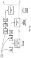
- Figure 4 is a flowchart diagram illustrating generation of control information based on received instructions and/or determined characteristics of the wireless medium.
- the transmit system 102 may receive instructions to modify at least one communication layer (e.g., a first communication layer). These instructions may be provided by a broadcaster, a carrier, or another entity. The instructions may be provided to modify transmit / receive operation to compensate for certain "conditions", such as changing viewer usage / viewing habits, e.g., increased viewing (and hence increase bandwidth requirements), equipment failure, broadcaster requirements, etc. In one embodiment, these instructions may be generated by software executing inside the transmission system 102 itself.
- the method may provide increased service relative to other periods, e.g., may allocate more of the available bandwidth to M/H services.
- bandwidth may be expanded or reallocated during the evening commute (e.g., 4 PM to 7 PM) to broadcast daily stock market summaries past market close to supplement a low bandwidth stock ticker present throughout the day.
- daily news/sports updates could be tailored during commute hours (e.g., 7 AM to 9 AM and/or 4 PM to 7 PM) for the screen resolution appropriate for handheld devices, and then scaled back during primetime hours to permit higher resolution programming.
- the generated control information may be based on anticipated usage scenarios.
- instructions may be provided to modify transmit / receive operation during commute times vs. prime time.
- drive-time (commute) bandwidth may be dominated by multiple low resolution streams that are frequently updated.
- audiovisual traffic during commute hours is generally more burst-like in order to accommodate user directed file downloads to browse and/or store content on mobile devices 112 for later viewing.
- prime time hours may involve a much greater amount of static programming that is consumed end-to-end.
- instructions may be provided to one or more transmission systems 102 to configure the transmit / receive systems differently during these different time periods having different usage patterns.
- the transmission system 102 can be modified based on typical user statistics and the nature of the content appropriate for different usage scenarios.
- usage scenarios can be characterized in terms of the following:
- the transmission system 102 may determine channel characteristics of the wireless communication medium and then use these determined channel characteristics to generate the control information.
- the method may determine channel characteristics based on information from an equalizer comprised in the receiver of one or more mobile device(s). The method may use known training sequences to determine channel characteristics.
- the transmission system 102 may transmit known training sequences over the wireless communication medium, and then receive information from the receiver regarding the reception of these known training sequences. For example, the method may deconvolve the channel based on the known training sequence(s) to determine the accuracy of the channel estimate.
- channel characteristics may not be known by the transmission system 102 unless specially equipped receivers are deployed in the broadcast area to provide feedback on a return channel reporting packet error statistics, receive SNR, etc.
- the receivers might additionally, based on the aforementioned receive characteristics, determine how to configure the communication layers and feed the necessary control information back to the transmission system 102 thereby comprising a closed system of control.
- the transmit logic 104 may determine a modification to a first communication layer based on the characteristics of the wireless medium. For example, if the received signal is weak, noisy or otherwise unreliable, resulting in lost packets, the method may increase the amount of forward error correction to compensate for the noisy channel and decrease the image resolution. If the wireless communication medium is determined to be relatively strong and robust, the method may decrease the amount of forward error correction, thus allowing for more transmission bandwidth, e.g., for higher image resolution or more channels.
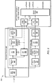
- the transmit logic 104 examines parameters of a plurality of communication layers. This may comprise examining parameters in various of the communication layers, e.g., as shown in Figure 16 .
- the transmit logic 104 may examine parameters in each of the presentation layer, the management layer, and the physical layer.
- the transmit logic 104 may also examine parameters of the other communication layers (the presentation layer and the physical layer) to determine if any changes are required to portions of these other communication layers, based on the requested change (e.g., to the management layer).
- the transmit logic 104 determines determine changes in one or more other communication layers based on the requested modification to the first communication layer. It is noted that the transmit logic 104 may in some instances determine changes in one or more other communication layers based on the requested modification to the first communication layer, and in other instances the transmit logic 104 may determine that no changes are required in one or more other communication layers based on the requested modification to the first communication layer.
- the transmit logic 104 may examine parameters of a plurality of communication layers in 166 and determine based on the parameters of the various communication layers that the instructed or determined modification to the first communication layer should itself be modified, e.g., to provide improved or optimized performance based on the current state of the plurality of communication layers. For example, if a modification to one or more parameter values in a first communication layer is determined in either 152 or 164, at 166 the transmit logic 104 may examine parameters of a plurality of the communication layers and determine that a different modification to the first communication layer should be made, possibly in conjunction with changes to other parameters in the first communication layer or changes to parameter values in other communication layers.
- Step 124 the configuration of the transmission system 102 is modified. Step 124 was described above with reference to Figure 2 .
- the transmit logic 104 generates control information configured to modify the first communication layer and possibly one or more other communication layers. Step 126 was described above with reference to Figure 2 . As discussed above with respect to 128 of Figure 2 , this control information may then be inserted into packets for transmission, e.g., to the various mobile devices 112.
- the receiver in the mobile device 112 transmits feedback information back to the transmission system 102.
- the receiver in the mobile device 112 may transmit the feedback information back to the transmission system 102 over any of various mediums, e.g., a return path, such as a cellular network or WAN/WAP, etc.
- the feedback information may comprise various types of information, such as packet error rates, packet loss information, receiver capabilities, user settings, etc.
- the transmission system 102 may then use this feedback information in determining how to adjust the broadcast system, e.g., which parameters to adjust in one or more of the communication layers in the transmission / receive systems.
- the receiver in the mobile device 112 may also transmit control information to the transmission system 102 to configure the transmission system.
- the receiver obtain various information, such as packet error rates, user input, etc., and may reconfigure itself (by changing one or more parameters in one or more communication layers in the receiver).
- the receiver may then generate control information (in a similar manner in which the transmission system 102 generates control information) and provide this control information to the transmission system 102.
- the transmission system 102 may then receive this control information and modify its capabilities accordingly, e.g., modify one or more parameters in one or more communication layers in the transmission system 102.
- the transmission system 102 is capable of modifying its configuration and transmitting information to the receiver in at least one mobile device 112 to modify its configuration, and the receiver in at least one mobile device 112 is capable of modifying its configuration and transmitting information to the transmission system 102 to modify its configuration.
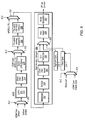
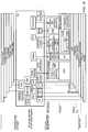
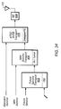
- FIG. 5 is a block diagram of an exemplary transmit architecture which may be comprised in the transmit logic 104.
- the transmit architecture may comprise a multiplexer 202 having a first input for receiving a media stream (robust stream) and a second input for receiving first control information (referred to as a VSIW (Variable Stream Instruction Word) Over Stream).
- the multiplexer 202 includes a control input that receives an XLC signal.
- the XLC signal determines whether the media stream 204 or the first control information 206 is provided as an output of the multiplexer 202.
- the output of the multiplexer 202 is provided to a robust encoder 212, e.g. LDPC (Low Density Parity Check).
- LDPC Low Density Parity Check
- the robust encoder 212 computes parity check bits based on the transmit data.
- the robust encoder 212 provides an output to a Block Interleave block 214.
- the Block Interleaver block 214 permutes the data block to minimize the impact of burst errors in the transport stream.
- the Block Interleave block 214 provides its output to Buffer 216.
- the Buffer 216 is coupled to provide its output to a first input of a multiplexer 222.
- the second input of the multiplexer 222 receives second control information, referred to as VSIW Over MPEG-2 TS.
- the multiplexer 222 includes a control input that receives an XLC signal.
- the XLC signal determines whether the output of the buffer 216 or the second control information 218 is provided as an output of the multiplexer 222.
- the output of the multiplexer 222 is provided to a Pre-pend training sequence block 224.
- the Pre-pend training sequence block 224 attaches the prescribed training sequences ahead of the packet data.
- the Pre-pend training sequence block 224 provides its output to a Pre-pend PID HDR block 226.
- the Pre-pend PID HDR block 226 replaces the MPEG-2 TS Header with an unassigned PID header affording backward compatibility to legacy receivers.
- the Pre-pend PID HDR block 226 provides its output to a first input of a multiplexer 232.
- the multiplexer 232 includes a second input 234 that receives an MPEG-2 TS (Transport Stream).
- the multiplexer 232 includes a control input that receives an XLC signal.
- the XLC signal determines whether the output of the Pre-pend PID HDR block 226 or the MPEG-2 TS 234 is provided as an output of the multiplexer 232.
- the output of the multiplexer 232 is provided to a Main Service Transport block 250.
- the Main Service Transport block 250 comprises a randomizer 252, an encoder 254, e.g., RS (Reed Solomon) encoder, Convolutional Interleaver 262, a Trellis encoder 264, e.g., 12-1 Trellis Encoder, a multiplexer 266, a Pilot insert block 268, and an 8VSB modulator 282.
- RS Random Solomon
- the randomizer 252 generates a random signal that is provided to the RS encoder 254.
- the RS encoder performs Reed Solomon coding and provides its output to the Convolutional Interleaver 262.
- the Convolutional Interleaver 262 permutes the transmitted data bits and provides its output to the Trellis encoder 264.
- the Trellis encoder 264 provides its output to a first input of 3 input multiplexer 266.
- the multiplexer 266 also receives inputs from the Segment Sync block 272 and Field Sync block 274.
- the Field Sync block 274 receives an input from two input multiplexer 278.
- the multiplexer 278 receives as a first input a signal VSIW Over Frame Sync.
- the second input of the multiplexer 278 is currently Reserved and not connected.
- the multiplexer 278 includes a control input that receives an XLC signal.
- the XLC signal determines whether the VSIW Over Frame Sync is provided as an output of the multiplexer 278.
- the output of the multiplexer 266 is provided to the Pilot insert block 268.
- the Pilot insert block 268 inserts a pilot tone in accordance with the ATSC 8VSB DTV Specification.
- the Pilot insert block 268 provides its output to the 8VSB modulator 282.
- the 8VSB modulator 282 performs 8VSB modulation on the received data and provides an 8VSB modulated output signal to an RF upconverter.
- the RF upconverter generates an RF (radio frequency) signal which includes the 8VSB modulated signal.
- the generated RF signal may then be transmitted by transmitter 106.
- the Transport Stream Encoding method can be described relative to the Main Service Transport as depicted in Figure 5 .
- the system shown in Figure 5 provides 3 different mechanisms for inserting control information into the transmitted stream. These 3 different mechanisms are represented by the three multiplexers and 202, 222, and 278.
- a fourth multiplexer 232 inserts unassigned packets comprising robustly encoded audio visual packet information and the associated control information in the standard transport stream,
- the "VSIW Over Frame Sync" signal provides the most robust means for transmitting the control information, but affords the least bandwidth for transporting control information.
- the "VSIW Over MPEG-2 TS” affords greater bandwidth for transporting control information spread in a manner to provide increased reliability.
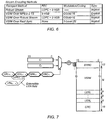
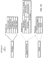
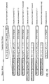
- each transport method can be characterized in terms of the error protection, modulation/coding and stream synchronization employed, as summarized in the table of Figure 6 .
- 8-VSB under the heading FEC refers to RS+TCM coding employed by the main service transport.
- a training sequence is pre-pended to the data field for use by certain receiver configurations. This field may be left empty ([]) if not needed.
- a PID is then pre-pended with the header field set to the prescribed value (zero-padded to the full 3-bytes) before being sent the main service transport. No additional modulation or coding is employed as part of the Robust Stream Encoding.
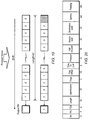
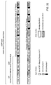
- Figure 7 illustrates encoding of command packets in a mobile digital television stream according to one embodiment of the invention.
- Figure 7 illustrates VSIW over MPEG-2 transport stream encoding.
- VSIW Over MPEG-2 TS requires that the VSIW is encoded and placed over Stream 0, known as the Main stream, as shown.
- the VSIW Over MPEG-2 will share the stream with stream 0 but does not have to be located in any particular place in the stream.
- VSIW Over MPEG-2 TS FEC - Multiplexed alongside the MPEG-2 TS, VSIW Over MPEG-2 does not employ additional FEC.
- VSIW Over MPEG-2 TS Modulation and Coding is shown in Figure 7 .
- ⁇ C 0 , C 1 ⁇ [2271 16 , 7B28 16 ]
- each codeword is modulated (i.e. selected) according to the intended information content, the result of which represents a single un-coded bit in the VSIW stream.
- the C 0 codeword is inserted whenever a ' 0 ' occurs in the VSIW stream; C 1 is sent whenever a '1 ' occurs thus occupying 2-bytes in the transport stream for each inserted information bit.
- the modulated code sequences [C ⁇ ⁇ C 0 , C 1 ⁇ ], selected according to bit content, provide inherent signal processing/spreading gain improving the reliability of stream communication relative to any bit transmitted individually.
- Figure 8 summarizes the stream framing parameters. Each bit in the stream is modulated using the length-16 codes as described above with spreading applied across SYNC
- VSIW Over MPEG-2 TS Stream Synchronization - SYNC is inserted at the start of each stream to assist the receiver in locating VSIW Over MPEG-2, potentially inserted anywhere within an 8-VSB frame.
- the sync field establishes the start of the intended information field. The remaining message stream is processed thereafter until the stream end is reached as indicated by the LEN field.
- VSIW Over Robust Stream is an extension of the robust transport method permitting VSIW to be communicated over MPEG-2 TS with extra error protection as described above for the Robust Stream Encoding.
- the VSIW only carries information relative to the stream that it is being transported under.
- the VSIW also must be placed at the start of a stream frame where a stream frame is the recycle point in the stream.
- VSIW Over Robust Stream FEC - VSIW Over Robust Stream employs the same additional FEC, i.e. LDPC, as that used for the Robust Stream Encoding.
- VSIW Over Robust Stream Modulation and Coding - VSIW Over Robust Stream uses the same code-spread modulation employed in VSIW Over MPEG-2 with the exception the SYNC field is omitted to conserve bandwidth.
- the process for coding VSIW Over Robust Stream can be outlined as follows:
- VSIW Over Robust Stream Synchronization is implicit in that the stream location is known by the receiver. For this reason the VSIW Over Robust Stream must be placed at the start of a stream frame where a stream frame is the recycle point in the stream.
- 82 of the 92 reserved symbols in the field segment sync are available to support extension of the standard. This is where the VSIW packet transmission occurs.
- VSIW Over Field Sync uses the 2-level (i.e. ⁇ 5) modulation employed in the surrounding sync symbols. Unlike the other VSIW methods, code-spread modulation is abandoned (along with the [SYNC]I LEN
- VSIW Over Field Sync Stream Synchronization - Synchronization is implicit in that the stream location and length are known by the receiver.
- Figure 9 illustrates a receive architecture in a mobile device 112 according to one embodiment of the invention. More particularly, Figure 9 illustrates an overview of digital RX processing that may be performed in the receiver of a M/H device 112.
- receiver 302 comprises Standard Demodulation 304, Standard Decoding 306 and M/H Stream Reception under VSIW Control block 308.
- the receiver 302 decodes an input signal yielding a stream of receive symbols at the output of the Standard 8VSB Demodulator 304.
- the output of the Standard Demodulator 304 is passed to the Standard Decoder 306 producing a standard 8VSB transport stream.
- the VSIW Decoder 416 is configured to search the receive signal for control packet information at the output of the Standard Decoder 306, the output of the M/H Decoder 418 and the output of Sync removal 410 corresponding to VSIW over MPEG-2 TS, VSIW over Robust Stream and VSIW of Field Segment Sync, respectively.
- M/H decoding 418 is applied in accordance with XLC commands recovered from VSIW decoding 416.
- the received transport stream is de-multiplexed 432 to produce a plurality of audiovisual streams corresponding to mobile and/or fixed services.
- the receiver 302 may be implemented in any of various ways, as discussed below with respect to Figure 13 .
- the signal processing stage operates to provide channel selection and filtering such that symbol data (3 bits) may be processed in subsequent stages.
- the signal processing may be performed by both analog (hardware) and digital (software).
- Analog signal processing may be performed by an RF Tuner, IF Filter and analog-to-digital conversion (not shown).
- Digital signal processing (DSP) comprises the rejection filters, equalizer 406 and phase tracker.
- the receiver 302 operates to remove (e.g., deconvolve) any unwanted channel effects from the received symbol stream. These effects include co-channel interference (e.g. NTSC), multi-path dispersion and Doppler shifting.
- deconvolved data is then analyzed to determine what adjustments are needed to the RF Tuner to improve symbol recovery.
- the received signal is provided to a Root Raised Cosine (RRC) filter block 402 which operates to filter the signal to match the RRC response applied at the transmitter.
- RRC filter block 402 provides its output to a Remove Pilot block 404.
- the Remove Pilot block 404 removes the DC-offset introduced by the pilot tone.
- the Remove Pilot block 404 provides its output to an EQ block 406 and to a Chanel Estimation block 408.
- the EQ block 406 reverses the channel effects estimated from the received signal.
- the EQ block 406 provides its output to a Remove Sync block 410.
- the Remove Sync block 410 provides Field Sync position information to the Channel Estimation block 408 and to VSIW Decoding block 416.
- the Remove Sync block 410 provides an output to an 8VSB Demodulation block 412
- the Chanel Estimation block 408 operates to determine the appropriate inverse channel response.
- the 8VSB Demodulation block 412 performs 8VSB demodulation on the signal and provides an output to Mobile/Handheld (M/H) Decoding block 414.
- the 8VSB Demodulation block 412 also provides an output to 12-1 Trellis Decoder 422.
- the Trellis Decoder 422 performs Trellis decoding on the received signal and provides an output to Convolutional Deinterleaver 414.
- the Convolutional Deinterleaver 414 reverses the bit permutation introduced by the Convolutional Interleaver.
- the Convolutional Deinterleaver 414 provides an output to Reed Solomon (RS) Decoder 426.
- the RS Decoder 426 performs block decoding.
- the RS Decoder 426 provides an output to De-randomizer 428.
- the De-randomizer 428 provides an output to VSIW Decoding block 416 and Stream Demultiplexer block 432.
- the M/H Decoding block 418 applies the additional FEC associated with the M/H transport as directed by the VSIW Decoding block 416.
- the VSIW Decoding block 416 operates to decode command information (VSIW commands) from received packets.
- the VSIW Decoding block 416 accepts input from three separate locations in the transport corresponding to VSIW over MPEG-2 Transport Stream taken at the output of the De-randomizer, VSIW Over Robust Stream taken at the output of the M/H Decoding block and VSIW Over Field Segment Sync taken at the output of the Remove Sync block, respectively.
- the VSIW Decoding block 416 provides cross layer control (XLC) information to the M/H Decoding block 414 and to Stream Demultiplexer 422.
- the XLC information comprises parameter settings destined for endpoints in the tree structure along with commands to traverse nodes in the tree as well as relative bandwidth and per stream coding rates needed to determine the multiplexing arrangement. The XLC information is discussed in greater detail below.
- the M/H Decoding block 418 and the VSIW Decoding block 416 are coupled to a Stream Demultiplexer 432.
- the Stream Demultiplexer 432 demultiplexes the various streams from the received signal to generate various individual audiovisual streams (e.g., digital television channels).
- the signal processing stage operates to provide channel selection and filtering such that symbol data (3 bits) may be processed in subsequent stages.
- the signal processing may be performed by both analog (hardware) and digital (software).
- Analog signal processing may be performed by an RF Tuner, IF Filter and analog-to-digital conversion.
- Digital signal processing (DSP) comprises the rejection filters, equalizer 406 and phase tracker.
- the receiver is configured to remove (i.e. deconvolve) any unwanted channel effects from the received symbol stream. These effects include co-channel interference (e.g. NTSC), multi-path dispersion and Doppler shifting.
- the deconvolved data is then analyzed to determine what adjustments are needed to the RF Tuner to improve symbol recovery.
- the receiver 302 (receive data processor) is configured to extract the encoded transport stream from the symbol stream recovered by the signal processor. Decoding is accomplished in 5 parts as shown in Figure 10 , these being: Sync Detection and Removal 316; Trellis Decoder 318; Data Deinterleaver 320; Reed Solomon Decoder 322; and Data De-Randomizer 324.
- Transport Stream Decoding is carried out consistently with the stream encoding methods employed by the transmitter.
- Transport Stream Decoding is responsible for recovering stream data whether associated with MPEG-2 transport, Robust transport providing additional error protection for M/H, or VSIW each of which is multiplexed under XLC control at various transport levels.
- the codeword size, k 4096 bits (512 bytes).
- Decoding is based on the same pair of orthogonal Gold codes ([ C 0 , C 1 ]) used by the transmitter. Receiving the codeword Co indicates that a 0 was inserted at the transmitter; C 1 indicates that a 1 was inserted.
- the purpose of the code-spread modulation is twofold: (i) it provides additional error protection in the form of signal processing gain inherent to the length-16 codes; (ii) provides a means to distinguish VSIW from other stream data assisting with stream synchronization.
- the CRC is computed over the combined LENIDATA to verify the integrity of the recovered data.
- VSIW Over Robust Stream Decoding proceeds similarly to that for VSIW Over MPEG-2 TS with the exception that LDPC decoding associated with the Robust Stream method is applied prior to assessing the code-spread stream content. Additionally, the synchronization step is omitted given that the stream location is known beforehand. The result of the robust decoding is demodulated using the length-16 codes. Finally, the CRC is calculated over the resulting LENIDATA field to ensure the integrity of the recovered data.
- VSIW Over Field Sync omits the code-spread modulation and [SYNC]
- a soft feedback mechanism can be added to improve the reliability of detection as depicted in Figure 12 .
- the final stage of ATSC 8-VSB decoding is to convert the MPEG-2 transport stream into audio and video data streams. More information on MPEG-2 can be obtained from the relevant ISO/TEC Standards for Video and Audio coding, respectively.
- LDPC codes are linear block codes with sparse parity check matrices H ( N ⁇ K )@ N , where each block of K information bits is encoded to a codeword of size N.
- the purpose of the decoder is to determine the transmitted values of the bits. Bit nodes and check nodes communicate with each other to accomplish that.
- the decoding starts by assigning the received channel value of every bit to all the outgoing edges from the corresponding bit node to its adjacent check nodes.
- the check nodes make use of the parity check equations to update the bit node information and send it back.
- Each bit node then performs a soft majority vote among the information reaching from its adjacent check nodes. At this point, if the hard decisions on the bits satisfy all of the parity check equations, it means a valid codeword has been found and the process stops. Otherwise bit nodes go on sending the result of their soft majority votes to the check nodes.
- Figure 11 shows an iterative (i.e. turbo) structure for decoding the additional LDPC FEC.
- the structure in Figure 11 comprises a Standard Demodulator block 336 and an Iterative Decoder 346 block, as shown.
- the Standard Demodulator block 336 comprises a Remove Pilot block 326, an EQ block 328 coupled to the output of the Remove Pilot block 326, a Remove Sync block 330 coupled to the otput of the EQ block 328, and an 8VSB Demodulator block 332 coupled to an output of the Remove Sync block 330.
- the Remove Sync block 330 also provides a Field Sync Position output to a Channel Estimator block 334.
- the Remove Pilot block 326 also provides an output to the Channel Estimator block 334.
- the Channel Estimator block 334 provides an ICF output to the EQ block 328.
- the Iterative decoder block 346 comprises a trellis decoder 338 which receives an output from 8VSB demodulator 332.
- Trellis decoder 338 provides an output to deinterleaver 340.
- Deinterleaver 340 provides an output to LDPC decoder 344.
- LDPC Decoder 344 provides an output to Interleaver 342.
- Interleaver 342 provides an output to the Trellis Decoder 338.
- LDPC Decoder 344 also provides an output to RS Decoder 348, which provides an output to De-randomizer 350.
- the Iterative Decoder block 346 is applied to the output of the standard 8VSB demodulation block 336.
- the iterative decoding 346 aims to improve receiver performance by maximizing the probability of a correct bit decision as observed by two concatenated decoders, these being the trellis decoder 338 and LDPC decoder 344, respectively, as depicted in Figure 11 .
- Each constituent decoder produces a set of soft-bit outputs comprising tentative bit decisions accompanied by the probabilities of the corresponding bits having been correctly decoded.
- the output of the trellis decoder 338 is de-interleaved 340 prior to passing soft-bit decisions to the LDPC decoder 344 which in turn produces soft-bit decisions and their bit probabilities.
- the set of revised bit decisions is then re-interleaved 342 and fed back to the trellis decoder 338 where the process begins again.
- the process is repeated for some number of iterations until satisfactory bit probabilities are reached across the set of decoded bits.
- Figure 12 extends the turbo decoding principal to VSIW codeword detection.
- the constituent decoders in the case of VSIW detection comprise the soft-output trellis decoder 338 concatenated with the MAP detector 374 matched to the VSIW codewords C 0 and C 1 , respectively 372.
- Soft-bits pass from the trellis decoder 338 to the MAP detector 374 through the de-interleaver 340, optional Reed-Solomon decoder 368 and de-randomizer 370.
- Soft-bit decisions from the MAP detector 374 are fed back through the randomizer 376 and interleaver 342 to the trellis decoder 338. The process is repeated for some number of iterations until satisfactory bit probabilities are reached across the set of decoded bits. Iterative decoding administered in the manner depicted in Figure 12 is intended to improve the reliability of VSIW detection.
- Figure 13 illustrates one embodiment of a multiprocessor system architecture that may be used to implement the receiver in a mobile device 112.
- Figure 14 is a more detailed illustration of a portion of the multiprocessor system of Figure 13 .
- the receiver may be implemented in any of various ways, such as one or more of: a single processor system, a multi-processor system, a programmable hardware element (also called an FPGA (field programmable gate array)), or an application specific integrated circuit (ASIC), or various combinations thereof.
- a single processor system such as a single processor system, a multi-processor system, a programmable hardware element (also called an FPGA (field programmable gate array)), or an application specific integrated circuit (ASIC), or various combinations thereof.
- FPGA field programmable gate array
- ASIC application specific integrated circuit
- the multi-processor system may comprise a parallel computational platform comprising multiple processors, memories (unified and/or distributed), and communication (or communication network) resources.
- An exemplary multi-processor system comprises a plurality of processors, wherein each of the processors is coupled to at least one other processor, and wherein there are multiple communication mechanisms between the respective processors.
- the multi-processor system may comprise a plurality of memories coupled to the processors. For example, the memories may be interspersed among the processors. More specifically, the multi-processor system may comprise a plurality of communication units interspersed among the processors, wherein each of the communication units comprises a memory and routing logic.
- the term "coupled" means directly or indirectly connected.
- An exemplary multi-processor system is the multicore HyperX architecture disclosed in U.S. Patent No. titled "Processing System With Interspersed Processors And Communication Elements” filed on June 24, 2003, Patent Publication No. US 20040030859 (patent application Serial No. 10/602,292 ), whose inventors are Michael B. Doerr, William H. Hallidy, David A. Gibson and Craig M. Chase, and which is hereby incorporated by reference in its entirety as though fully and completely set forth herein.
- the central core building block of the HyperX architecture is a scalable unit-cell-based hardware fabric, a HyperSlice.
- the entire hardware architecture is formed by replicating this core unit-cell to create a multi-core parallel processing system.
- Each HyperSlice contains a DMR (Data Memory and Router) and Processing Element (PE).
- DMR Data Memory and Router
- PE Processing Element
- the DMR provides data memory, control logic, registers, and routers for fast routing services to the processing resources.
- the hardware fabric is created by joining HyperSlices together, forming the on-chip network. This on-chip network operates independently and transparently to the processing resources. It provides on-demand bandwidth through a real-time programmable and adaptable communication fabric between HyperSlices supporting arbitrary network topologies of functions or system implementations. Coordinated groups of HyperSlices may be formed and reformed "on-the-fly" under software control. This ability to dynamically alter the amount of hardware used to evaluate a function allows for the optimal application of hardware resources to relieve processing bottlenecks.
- the DMR provides nearest neighbor, regional, and global communication across the chip and from chip to chip.
- the DMR does this through four different transfer modes; memory to memory, memory to register, register to memory, and register to register. Each of the transfer modes may physically use the DMR resources to send data/messages differently depending on locality of data and software algorithm requirements.
- a "Quick Port" facility is provided to transfer a word of data from a processor to anywhere rapidly.
- DMA Direct Memory Access
- the use of shared memory and registers is the most efficient method of data movement.
- routing fabric is the most efficient method. Communication channels can either be dynamic or static.
- Dynamic routes are set up for data transfer and torn down upon the completion of the transfer to free up routing resources for other data transfers. Static routes remain in place throughout the program execution and are primarily used for high priority and critical communications. All data transfers and the choice of communication channel are under software program control. Multiple communication channels exist to support simultaneous data transfer between any senders and receivers.
- a HyperX multi-processor system may comprise either a heterogeneous or homogeneous array of PEs.
- a PE may be a conventional processor, or alternatively a PE may not conform to the conventional definition of a processor.
- a PE may simply be a collection of logic gates serving as a hard-wired processor for certain logic functions where programmability is traded off for higher performance, smaller area, and/or lower power.
- the cross-layer control (XLC) system is intended to provide a manageable, flexible, and extensible framework that expands the current ATSC system layers to enable M/H services.
- XLC cross-layer control
- the current ATSC system layers are currently defined (in A/53 Part 1) as:
- a linear structure (as opposed to a tree structure) is used to facilitate transmission of the control information as illustrated below: Syntax # of bits List Header () ⁇ Parameter 1 k 1 Parameter 2 k 2 Parameter 3 k 3 ⁇ ⁇ ⁇ Parameter N k N ⁇
- the parameter list comprises a mixture of real numbers and enumerated types knowledge of which is accessible to the transmitter and receiver to support the enumerations.
- a tree structure is used, as described herein. Due to the recent proliferation of wireless technologies and services, any single encoding technique, comprising forward error correction and digital video or audio encoding, does not work best in all situations, no matter the layer applied. Therefore, to plan a transmission system dependent on any one technique is problematic from the outset.
- Various embodiments of the present invention provide a cross layer and extendable network interconnection methodology.
- PSIP Program and System Information Protocol
- the XLC system provides for management of an adaptable and extensible [for future proofing] protocol that enables dynamic flexibility in services required to meet Broadcasters' technical and business needs.
- Figure 16 illustrates an example of the XLC functional elements and the manner in which they may control the various communication layers. As shown in Figure 16 , the XLC methodology allows visibility into and control of the plurality of different communication layers.
- the functional elements within the XLC block provide for control according to the tree structure described herein.
- the blocks outside of the XLC correspond to branches of the tree structure, and the functional elements comprised within the XLC block provide for control of these blocks.
- the transmit / receive systems each include a plurality of communication layers.
- Each of these communication layers has associated parameters whose values can be changed to affect the operation of the respective communication layers. These parameters are arranged in a tree structure.
- the XLC block includes various functional elements that are responsible for modifying the parameter values in or according to this tree structure.
- Table 1 illustrates a hierarchical view of the XLC protocol fields and associated parameters.
- Table 1 XLC Protocol - A Hierarchical View Table 2: XLC Protocol - A Hierarchical View Hierarchical View of Cross Layer Control (XLC) Field Dependencies Parameters Level-1 Level-2 Level-3 Level-4 Level-5 Level-6 Level-7 Physical Enable/Disable PH1 RF Training Sequence Dep. on PHY Type TBD Continuous or Burst Mode Flag Other TBD PH2 FEC Type Dep. on PHY Type TBD Rate Dep. on PHY Type TBD Interleaver Length Dep.
- TBD Number of Streams At least 1 PHY Type ATSC 1.0 Default A-VSB Default MPH Default Micro/Thom Default Other TBD PHY States Current Multiplexer State State Current Stream Interleaver State Stream ID State Current Location in Streams transport packet (Bytes) Stream ID State XLC Packet Offset Stream ID Offset Other TBD Other TBD Management Enable/Disable M1 Transport Enable/Disable MPEG-2 TS Enable/Disable IP Enable/Disable UDP Enable/Disable Other Enable/Disable M2 Signaling Enable/Disable XML Enable/Disable SIP Enable/Disable SAP Enable/Disable SDP Enable/Disable M3 Announcement Enable/Disable ESG Enable/Disable EPG Enable
- Table 2 illustrates XLC protocol fields and associated parameters.
- Table 2 XLC System Sub-Packet Definition ID Field Name Description 0.0 Disable Disables System 0.1 Physical Controls Physical layer 0.2 Management Controls Management layer 0.3 Presentation Controls Presentation layer 0.4 Packet Control Controls the Packet Control 0.5 Other TBD
- Table 3 below illustrates physical definitions of XLC sub-packet IDs.
- XLC Physical Sub-Packet ID Table 3 XLC Sub-Packet - Physical Definition ID Field Name Description 0.1.0 Disable Disables Physical 0.1.1 RF Controls the RF layer 0.1.2 FEC Controls the FEC parameters for a stream 0.1.3 MPEG-2 TS (legacy) Controls the transport streams 0.1.4 Number of Streams The number of streams being transmitted by the PHY 0.1.5 PHY Type The default setting for the type of PHY 0.1.6 PHY State Returns the current state of the PHY 0.1.7 Other TBD
- the Augmented Stream sub-packet describes the encoding method of the augmented stream.
- An augmented stream contains the block forward error correction for a non-robust stream (e.g. the main stream).
- the sub-packet has a Stream ID field and a Stream [System] Encoding Type field. If an encoding method is unknown to a receiver the stream will not be decoded.
- the Main stream data is encoded in blocks the size of which is determined according to the encoding method.
- the stream does not need to encode main transport stream data on any particular boundary.
- an augmented encoding method block size must not exceed the multiplexer base and the check block size must be able to be sent over the stream in the streams data bandwidth.
- S bits nb + r , where S bits is the augmented stream size in bits, n is the number of full check blocks in a stream, b is the number of bits in a check block, and r is the number of remainder bits.
- An Augmented stream is preferably zero padded with r bits that will be ignored by the receiver in order to maintain the correct stream rate. It should be noted that a number of LDPC methods will be required for various rates. An encoder should select the highest encoder rate that can be sustained in the available bandwidth otherwise the augmented stream cannot keep up with the main stream.
- Figure 17 shows an LDPC with a small 1152 bit block encoding size simulated over an AWGN channel.
- a pronounced benefit to the main stream can be seen by using an augmented stream over just small block size. Adjusting block size to longer lengths will increase performance.
- Figure 18 illustrates the manner in which streams at various rates are multiplexed. Referencing a common multiplexer base derived from the greatest common divisor among the relative stream rates, streams are multiplexed in proportion to fill the available MPEG-2 TS bandwidth. Any unused bandwidth is filled by null packets as depicted in Figure 18 .
- the method for multiplexing normal and robust data at a rate that is adaptable in real-time is transmitted to the receiver through the VSIW.
- VSIW VSIW
- the MUX rate developed can be n/m where n is any integer between 0 and m. This allows the robust stream to be added at any packet rate within the transport stream. At the receive end, this allows the transport stream to tell the decoder whether or not a packet is robust. This multiplexer rate drives a sequence generator that will appropriately distribute the packets.
- a sequence generator Given a multiplexer ratio for each of the streams, a sequence generator can construct a multiplexing and de-multiplexing sequence between the [normal and robust] streams. As an example, we select the first stream A such that its length a , a multiple of 128, is less than the second stream B of length b, a multiple of 496. These multipliers may be taken to be some measure of data rate for each stream.
- a basic sequence generator for merging two streams by data segments is constructed as follows.
- the process of multiplexing may be continued either by recursion, in which later sequences to be added are distributed more sparsely, or they may be introduced immediately for even distribution in a generalization of this process.
- the descriptor envisioned here for the multiplexing of streams is more suited to the former case, with the highest rate streams combined first.
- SR Shift Register
- Figure 19 illustrates exemplary Shift Register (SR) Operation.
- the generated Sequence BBBA-BBBB-ABBB-BABB-BBAB-BBBA-BBBB-ABBB-BABB-BBA showing the 8:31 of stream A and stream B.
- This sequence is the repetition sequence for the 2 mux streams.
- burst mode method multiplexing output of normal and robust data is performed on a block by block basis.
- the rates are specified in the LTP Field Definition.
- the bursts will be transmitted from lowest stream number to highest stream number, where stream 0 is the 1 st stream.
- the number of streams sub-packet describes the number of data streams that are being transmitted. This includes all streams, main and robust if present.
- the count range is from 1 to 2 p c , where p c is an integer, but is transmitted as 0 to 2 p c -1.
- the PHY Type sets the value for all hierarchical sub-fields of the XLC Physical Layer parameters to a default mode. This offers a low bandwidth method for loading predefined defaults of a specific physical type.
- the number of PHY Types listed is four, however as in all field and associated parameter definitions of the XLC, there is not a theoretical limit by design. Thus, the number of PHY Types can be represented as 2 p c , where p c is an integer.
- the PHY States field describes the current states of the physical layer so that a receiver after acquiring lock knows where the data starts and can initialize the PHY to synchronize to the transmitter. It is assumed by the receiver that the default states are 0, if not specified.
- the functionality covered corresponds to the Data Link Layer (DLL), Network Layer, Transport Layer and Application Layer of the OSI Reference Model.
- the services supported include Streaming AV, File Transfer, Datacasting, Signaling, Announcement, Conditional Access (CA), Pay Per View (PPV) and Digital Rights Management (DRM).
- service protection, content protection, service discovery, handoff, interactive support, QoS monitoring, and notification is shown in Figure 16 .
- the OSI Layers are shown on the left side with corresponding ATSC functionality is described on the right.
- the carriage method selected must provide a method for minimizing the effects of latency and jitter, while supporting efficient bit stream splicing in optimal locations.
- the pertinent performance metrics for the M1-Transport layer are throughput and reliability.
- MPEG-2 TS over IP MPEG-2 TS over RTP
- MPEG-2 TS over RTP MPEG-2 TS over RTP
- native RTP NRTP
- SRTP secure counterpart
- IP is a data oriented protocol used to switch packets over a network. It is responsible for path determination and local addressing. IP is a connectionless protocol, no prior setup of the network path is required to communicate to a host it has never communicated with before. IP protects the header with a checksum, but provides no protection for the data. If a packet is received and the Header Checksum is bad, the packet will be dropped.
- Figure 20 illustrates an IP Header Format.
- UDP User Data Protocol
- UDP is a unicast, best effort delivery protocol, responsible for end to end delivery.
- UDP is analogous to TCP without the acknowledgment and retransmission.
- UDP is used instead of IP when sensitivity to time of delivery takes precedence over robust packet delivery.
- UDP does port mapping and so can be used to map a stream to a port if a particular application is listening on (Application Layer multiplexing).
- the Source Port and Checksum field use is optional. If they are not used, they should be populated with non zero data (preferably a non repeating sequence) to prevent hackers from using knowledge of known values in known locations to break the security protection implemented.
- Figure 21 illustrates a UDP Header Format.
- PES is a variable length header encapsulating an elementary stream in the MPEG data packaging.
- each UDP packet is capable of carrying 7 TS packets.
- the PES stream overhead is variable and dependent on the Elementary Stream (ES) length, and is therefore not considered in the calculations.
- the overhead for MPEG-2 TS over UDP and other composite streams are shown in Table 28 through Table 31.
- a maximum packet length of 1500 bytes is assumed. This is also known as the Maximum Transmission Unit (MTU) for transmission over an Ethernet network without triggering fragmentation. Fragmentation can result in increased latency and jitter, as well as increased packet loss.
- MTU Maximum Transmission Unit
- Signaling is the process of communicating control information for the elementary streams to configure the receiver to demultiplex and decode the various program streams. for the components of the desired program, and to reassemble them.
- a program is defined as a set of elements with a common time base and the same start and stop times.
- Figure 23 illustrates a Secure Real-Time Transport Protocol (SRTP) Packet Format.
- SRTP is a profile of Real-Time Transport Profile (RTP).
- RTP Real-Time Transport Profile
- SRTP supports confidentiality (encryption), message authentication and replay protection for the RTP traffic and the Real-Time Transport Control Protocol (RTCP) communications for both unicast and multicast traffic. Utilization of the full security features is optional.
- the protocol can be utilized as RTP or RTCP plus the authentication feature in its minimal configuration.
- SRTP is responsible for the sequencing and time stamping of the streaming media.
- RTP is a standardized packet format for delivery of audio and video data over the internet.
- the RTP functionality allows data to be modified over the transmission path more easily than UDP alone.
- RTP allows sequence reordering of packets, supports ad insertion/stream splicing, error recovery, fast channel change, QoS monitoring and compatibility with voice and video conferencing applications.
- the protocol is supported by IETF, DVB and ETSI.
- SRTP/RTP protocol does not include any support for multiplexing capability.
- UDP the underlying encapsulation provides the multiplexing support.
- Each SRTP stream must carry timing information to be used to synchronize the stream on the receive device.
- SRTP supports AES in counter mode (AES-CTR) as its default algorithm for encryption.
- AES-CTR AES-CTR
- the AES algorithm supports two modes, counter and output feedback mode.
- Counter mode is optimal for ATSC M/H because it allows access to individual blocks, which is essential on a unreliable medium where packets may be lost.
- the default encryption key is 128 bits and the default session salt key is 122 bits.
- Authentication, integrity and replay protection are supported by use of the HMAC-SHA1 algorithm.
- the algorithm produces a 160-bit result and the first 80 bits are extracted and appended to the packet.
- the authentication and encryption coverage are shown in 24.
- Key derivation of all keys needed per session is from one master key in a cryptographically secure way.
- the master key needs to be distributed to the end user only once, using the MIKEY key management protocol.
- RTCP is a control protocol that works with of the RTP Control protocol. It is used to monitor the delivery and packing of the SRTP data. It provides QoS measures by periodically sending statistics to SRTP users. Because the ATSC M/H is a unicast protocol, the SRTCP needs to be adapted to providing the feedback through back channels. The data collected to support QoS statistics would be held on the receiver until a back channel became available, via opportunistic cellular or WAN/WAP capable devices. The size and scope of the data could be scaled per the target platform and the functionality as a whole could be optionally disabled by the user. The anonymous statistical data could be utilized by the Broadcasters to adjust their transmission parameters and set their pricing for various tiers of advertising (mapping of coverage area).
- File delivery support is required by several of the planned services including PPV, CA, Datacasting, and Notification (alerts, billing, location, targeted advertisement).
- the file delivery should be internet compatible so that the broadcasters can efficiently transfer their data throughout the Broadcast Network and take advantage of the wealth of internet IP already developed.
- FLUTE File Delivery Over Unidirectional Transport
- ALC Asynchronous Layer Coding
- ALC is a protocol designed to support massively scalable multicast distribution.
- ALC supports FLUTE by taking the objects handled in FLUTE and generating packets of appropriate size and rate to transfer them reliably.
- ALC specifies the session description for receivers who wish to join, but does not specify how the session information is transferred.
- ALC also supports massively scalable congestion control.
- FLUTE handles data as objects, saving the context.
- FLUTE is a mechanism for signaling and mapping the properties of a file to concepts in ALC in such a way that the properties and context can be restored and the files delivered appropriately at the receiver.
- FLUTE may fix the transmission rate for the files transferred, for the duration of the session.
- FLUTE supports five types of file delivery sessions:
- Static File Delivery Session is a session where the files to be delivered are predefined. The version of a file may change during the session, but only one version of a file is delivered at any given time.
- Fixed Content Delivery System FCDS
- FCDS Fixed Content Delivery System
- DFDS Dynamic File Delivery System
- Static File Delivery Carousel is a time unbounded file delivery system where the set of files and their version are static. The objects arrive in a set pattern that repeats periodically.
- Dynamic File Delivery Carousel is a time unbounded file delivery system with a changing set of possible added/deleted/changed files being delivered.
- All datacasting data can be localized per GPS (GEO location) information or participation in selected user groups.
- End user devices can monitor streams per subscription and per location information with data tagged to facilitate extraction according to user interests. Examples include:
- Data can be cached opportunistically while the user has their device powered.
- Services may include
- Service discovery is the process of scanning channels, locating transmitters in range and taking a survey of offered services at each transmitter available to the user.
- the transmitter transmits a table of services with the data for ESG/EPG for their station.
- the data in this table can be augmented to carry information for all programming available in the area. All the information should be available on each channel, and should include programming for at least the next 48 hours.
- Another informational unit will be needed to package the information for all other services from all other channels, which should include the support parameters needed to receive a stream.
- Some devices will be low cost, low power and will not be able to receive all streams/services.
- the support parameters can be used to select streams/services that a given device is capable of processing.
- Handoff in the Broadcast network should be seamless and invisible to the user whenever possible. Numerous handoff cases should be considered in the design of a handoff algorithm. Three of those cases are presented here.
- Figure 24 illustrates handoff cases for SFN and non SFN broadcasters.
- the first type of handover will be between two towers in a Single Frequency Network (SFN).
- SFN Single Frequency Network
- This case is shown in Figure 24 as mobile device X leaving the coverage area of tower C and moving into the coverage area of tower A.
- the transmit signals are synchronized, and the program content is the same for both channels.
- the signal at the handover point will look like a strong multipath case, but will otherwise be inherently seamless.
- the second case is shown as mobile device Y leaving the coverage area of tower A, but proceeding into an area without broadcast coverage. Finding no other tower to complete the handover, the expected behavior is for the radio to preserve the quality of service as long as the current connection is maintained.
- the third case is shown as mobile device Z leaving the coverage area of tower B and proceeding toward tower D, which is not in the SFN, and so may have the same content as the viewer was consuming, but on a different channel.
- the content may not be as well synchronized.
- a method of preserving the service viewing, while changing to the new channel and re-synchronizing is needed.
- a solution for these requirements involves using the geo-location of the towers in the vicinity, which can be known, and the geo-location of the end user radio, which can be obtained if the end user radio has positioning capability. It is reasonable to assume that most mobile devices will have this capability in the near future. Several mobile device manufacturers already include GPS receivers in their devices.
- QoS Service Monitoring
- This section addresses methods for giving the Broadcasters capability for monitoring statistics.
- the ability to monitor performance is one measures of the system to maximize the effectiveness of the system.
- the possibility of an interactive network allows for near real time network optimization. It is possible for the Broadcaster to receive feedback on the quality of end user experience through multiple paths. With a continuous stream of information feedback, the Broadcaster can periodically re-optimize the coding schemes, data rates, content offered in robust streams, etc. For example, the Broadcaster could offer a popular movie to a given multicast group, and once a sufficient number of orders is received, can dedicate a robust stream for download to the receiver. If the Broadcaster wants to evaluate a more efficient coding scheme, it can use XLC to program a subset of receivers and collect statistics to monitor the effectiveness of the new scheme on a sample of the end user equipment. The receiver might additionally determine the need for change in the current configuration of the communication layers and feed control information back accordingly to configure the transmitter.
- the Broadcaster can provide a network of representative receiver devices that will be deployed around populated sites in the Broadcast Area.
- the sensors can be mounted on buses, trains, in static locations and can be given to targeted users. The data sent back can be used to optimize in near real time the Broadcast network with respect to weather, QoS statistics and even location.
- receivers can be further used to determine channel utilization in terms of the number of devices tuned to consume particular program content, time watched, frequency of viewing, etc as a method of audience measurement akin to the Nielsen Ratings.
- CA Conditional Access
- the recommended strategy for supporting conditional access is the solution devised by the DVB group.
- the component parts are as follows:
- the DVB system uses a combination of scrambling and encryption to protect the media content.
- the transmitter sends a key to use in descrambling the stream using a decryption smartcard.
- the scrambling keys are passed in an encrypted entitlement control message (ECM), and are changed approximately every 10 seconds.
- ECM entitlement control message
- the permission to descramble the stream is passed in a separate message called the entitlement management message (EMM), which is changed every 12 minutes.
- DCAS Downloadable Conditional Access System
- a Pay Per View (PPV) model for content delivery makes the offered content available to a viewer on a limited time basis.
- the model does not currently support permanent content retention.
- Material sent to end user would be time stamped for viewing during a given interval of time.
- the replay mechanism will check the timestamp to validate content for replay.
- the content is usually encrypted using the AES methodology specified for SRTP.
- the VSIW packet structure provides a management organization framework for transmitting the XLC protocol that enables real-time and dynamic configurability, flexibility, and extensibility of the system.
- the VSIW packet is designed to be configurable and extensible to support dynamic and future service capabilities.
- a VSIW packet is made up of a series of single VSIW Sub-Packets.
- Each VSIW Sub-Packet contains at least one XLC command, and in one embodiment contains only one XLC command.
- the VSIW converts the XLC non-systematic tree mapping known as the logical view to a systematic tree mapping known as the physical view.
- extension of a VSIW packet structure uses a special SPID value. Since the SPID is only 3-bits, it supports values from 0 to 7. The VSIW uses node 7 to identify a node extension of 7 more values.
- a VSIW packet can have 8 to m bits, where m is theoretically unbounded. This is further broken down into sub-packets
- Table 112 below illustrates descriptions of the VSIW packet structures for a single sub-packet.
- Figure 26 illustrates the VSIW Packet Structure according to one embodiment.
- Figure 27 illustrates the SPID Leaf Node Structure.
- Each Command IDs payload may have a structure or just a value.
- the structure is defined as a 2-bit SSPID field plus payload.
- the payload On the leaf SSPID node the payload is a stream plus a value/setting or just a value/setting.
- Figure 28 illustrates an example of the VSIW Packet Structure.
- the packet content describes how the receiving logic should navigate the tree structure and ultimately how to set parameter values at a leaf node within the tree structure.
- a Sub-Packet ID is generally specified from a parent Sub-Packet ID, e.g., the parent may be the root of the command tree or some other point in the tree.
- the parent may be the root of the command tree or some other point in the tree.
- the tree traversal structure or branch points should be specified.
- the Sub-Packet Branch ID describes a list of descendent branch points in the XLC command tree. To descend multiple nodes at a time requires setting the Sub-Packet ID field to 111 b which specifies the Sub-Packet Branch ID. This also changes the data length field to 3-bit increments. The concatenation of multiple packets works the same.
- a Branch point is made of 1 or more 3-bit fields. The most basic branch is a value from 0 d to 6 d . A value of 7 d (111 b ) assumes the branch extends into a second 3-bit field, making the branch point range from 7 d to 13 d . A branch point is complete when the last field is not 7 d (111 b ). The remaining 3-bit fields then start a new branch point. Using this method, a branch value can extend indefinitely.
- Figure 29 illustrates a pictorial example of descending and ascending the tree structure.
- the commands contained in the VSIW packet may comprise: setting a root node in the tree structure (navigating to a root node in the tree structure), instructions to navigate within the tree structure (up or down in the tree structure, i.e., toward a root node or toward a leaf node), and setting a parameter value in a leaf node of the tree structure.
- the VSIW packet may also comprise one or more commands for adding one or more nodes to the tree structure, thus extending functionality to include additional parameters in the tree structure.
- a new coding method may be introduced in a later revision of the M/H protocol.
- the transmit system 102 may transmit control information containing a command to add one or more nodes to the current tree structure to add the corresponding parameters for this new coding method to the tree structure.
- this new coding method is represented by a new branch in the tree thereby extending the node associated with FEC.
- a new codec type might be added under the Audio or Video Codec nodes or a new method of file delivery and associated parameter set may be added to extend functionality associated with the management layer.
- VSIW Variable Stream Instruction Word
- the VSIW Packet is encapsulated inside a VSIW transport packet.
- the packet consists of a length field (LEN) (extensible as needed to accommodate long data fields) followed by a variable length data field (DATA).
- LEN length field
- DATA variable length data field
- a CRC length-16 is computed over the combined LEN 1
- the stream framing parameters are summarized in Table 114, below.
- Orthogonal Gold sequences with length 2 m where m equals the number of bits transmitted is used to encode the VSIW packet to be transmitted.
- a choice to use two 32 length sequences or one 64 length sequence is provided.
- a Sync code is employed that uses one 16 length sequence where only 4 of the 16 codes are used. This corresponds to 80 symbols.
- Tables 115 and 116 define the encoding for two 32-length sequences and one 64 length sequence, respectively.
- a variable stream instruction word (VSIW) packet is formed by first choosing a packet encoding structure, A or B, as described above. Once the packet encoding structure is chosen, the corresponding instruction word pair (IWP) sync code is used as described in Table 117 below. This is identified as SIPA and SIPB each defined by an orthogonal Gold sequence for packet structures A and B, respectively. This sync method is also used to create variable length VSIW instruction word by using the instruction continuation sync codes.
- IWP instruction word pair
- Each transmitted VSIW instruction word must be sent as a pair to conform to the ATSC DTV field sync requirements since the codes are not zero mean.
- the first VSIW instruction word is sent normally and the second is sent inverted.
- the normal and inverted state of these bits is determined by the second PN63 in the sync field, which is inverted every other field sync. This has the effect of constructing a zero mean signal. This is also to our advantage since the method of receiving is based on repetitive summation of the VSIW instruction words.
- a VSIW is sent 2n times in a row, where n is an integer and which determines the repetition rate of the VSIW.
- the repetition rate and packet encoding structure must not change once a VSIW packet is formed, but can be changed at the start of a new VSIW packet.
- the VSIW repetition rate can be determined empirically at the receiver through the summation and correlation of the IWP sync code in each VSIW.
- Figure 30 illustrates cross-correlation peaks of IWP sync, for a repetition rate of three.
- the repeat pattern may be used to improve the likelihood of reliable reception.
- all VSIW are made equal in weight by normalizing signal strength to +/-1. We keep summing the VSIW until a peak is found between two adjacent VSIW averages. The number of VSIW to get a peak is two times the repetition rate of the IWP. Averaging over many VSIW after equalization reduces vulnerability to noise. A constant repetition rate within a packet can be detected. There are other methods not discussed here that may yield better noise immunity.
- Figure 31 is a flowchart for detecting VSIW repetition rate. Figure 31 illustrates how to use the repeat pattern (shown in Figure 31 ) to improve the reliability of the reception.
- a VSIW packet should also be a minimum of a VSIW instruction word pair, with the second VSIW containing an IWP instruction sync code. To continue the message beyond two VSIWs requires alternating between the two instruction continuation codes (MC0, MC1).
- FIG 32 illustrates a VSIW packet.
- the VSIW packet has various sync codes and data codes, as shown.
- This section describes using XLC to extend the current ATSC 1.0 (A/53) DTV Standard to support M/H services without any change to the legacy physical layers. Two modes of transmission are described, continuous and burst.
- XLC commands are sent over the 8-VSB Physical structure via the Variable Stream Instruction Word (VSIW) packet structure.
- VSIW Variable Stream Instruction Word
- the VSIW is then encoded into a transport stream that is either contained in the 8-VSB Field Sync Segment or the MPEG-2 TS.
- a complete VSIW packet detailing any deviations from the system configuration defaults is preferably sent at regular intervals.
- the interval length only effects the acquisition time of a receiver to the channel since it cannot start decoding robust streams until it receives a VSIW defining all the streams.
- a packet can occur anywhere in the data stream and can be fragmented but starts with a sync header.
- the multiplexer For burst mode the multiplexer sends N packets for each stream. The number of packets sent per stream is specified by the stream multiplexer rate. This enables a receiver to shut off during transmission of other streams, if it only wants to receive a particular stream. On channel acquisition the receiver must find the VSIW in the main stream telling it the locations and encoding of all the streams.
- the cross layer control (XLC) extension language is a binary structured language developed to facilitate the communication of structured data across information systems of various structures and protocols.
- the data structure may be tree based.
- the language is composed of a combination of commands for navigating the tree, modifiers for describing sections of the tree, and data for specifying selections or values corresponding to the nodes and/or sections of the tree.
- the method is not text based, i.e., is not human readable, but rather is more suited to communication in systems where bandwidth is at a premium and efficiency is very important.
- the method described herein includes a set of commands that allows the language to refer to groups of nodes (selections of the tree) in a very efficient manner akin to run length coding.
- communication of system versioning must be executed outside of the system being versioned.
- Figure 33 depicts various methods of transmission diversity, e.g. time and/or frequency from a single transmitter or time/frequency/spatial involving multiple transmitters, by which service reliability can be improved, in the presence of burst noise or deep channel fading for example.
- transmission diversity enables nested stream encoding where similarly to main stream augmentation, multiple complementary streams are transmitted, separated in time/frequency, containing additional code bits (non-systematic encoding) to be associated at the receiver with the primary data stream which may contain a mix of code and data bits (systematic encoding).
- Nested encoding can be further extended to include multiple encodings in which each resultant stream retains sufficient information to permit decoding when received alone or when received in tandem to achieve a lower receive threshold. In other words, both the primary and secondary streams employ systematic encoding.
- Figure 34 illustrates the method of transport tunneling to enable future extensibility.
- transport tunneling can be employed to ensure longevity of the M/H standard.
Description
- The present invention relates to the design of a robust mobile television broadcast system, and more specifically in one embodiment relates to the enhancement of the current 8-VSB-based ATSC Digital TV (DTV) broadcast system for mobile services to mobile and handheld devices.
- The ATSC (Advanced Television Systems Committee) standard relates to a digital television format which will replace the analog NTSC television system. The ATSC standard is a high definition television standard that produces standard 4:3 or wide screen 16:9 images up to 1920×1080 pixels in size - more than six times the display resolution of the earlier NTSC standard. The ATSC standard makes provisions to transport multiple standard-definition "virtual channels" broadcast on a single 6 MHz TV channel. The ATSC standard also includes "theater quality" audio using the Dolby Digital AC-3 format to provide 5.1-channel surround sound. The ATSC standard also provides numerous auxiliary datacasting services.
- The ATSC standard uses the MPEG-2 systems specification for encapsulation (transport) of data. More specifically, ATSC uses the 188-byte MPEG transport stream packets to carry data. MPEG-2 is also referred to as "transport stream", "MPEG-TS", or simply "TS". At the receiver side, before decoding of audio and video occurs, the receiver demodulates and applies error correction to the signal. Then, the transport stream may be demultiplexed into its constituent streams. A video codec, e.g. MPEG-2, H.264, VC-1, is used for encoding and decoding video, subject to certain constraints.
- Previously, mobile reception of digital television stations transmitted using the ATSC standard has been difficult to impossible. For example, mobile reception of digital television stations is very difficult when moving at vehicular speeds.
-
WO 2006/010373 A1 describes a video-communication service in which a separation in different components of the video-communication is caused at the telephone equipment of the users (e.g. a separation in a video and in a voice component). The different components are transmitted on different connections between the telephone equipment of the users. The users have the possibility of selectively dropping anyone of the different connections. - There is still a need for an improved system and method for transmission and/or reception of digital television signals for improved mobile reception.
- The present invention provides a solution according to the subject matter of the independent claims.
- Embodiments of the invention relate to an improved system and method for transmission and/or reception of audiovisual information, e.g., digital television signals, for improved reception, and in particular to improved mobile reception. Certain embodiments relate to a digital television broadcast system which comprises a transmission system and one or more devices, e.g., mobile devices. Each of the mobile devices may include a display for presenting video information and one or more speakers for presenting audio information. Thus each of the mobile devices may include television-like capabilities for presenting received television channels as described herein. The digital television broadcast system may also of course include stationary devices.
- The transmission system is configured to transmit audiovisual information (e.g., television signals / channels) to the mobile devices in a wireless manner. The
mobile devices 112 may receive and present the audiovisual information, e.g., receive and present the digital television signals / channels. The transmission system may also be configured to transmit audiovisual information (e.g., television signals / channels) to stationary devices (stationary televisions) in a wireless manner. - The transmission system comprises a transmitter as well as transmit logic. The transmit logic is adapted for receiving and/or storing audiovisual information (e.g., television data) and for generating packets containing the audiovisual information. The transmit logic may generate packets according to the ATSC (Advanced Television Standards Committee) standard, e.g., using 8-VSB modulation. In one embodiment, one or more of the digital television channels are intended for stationary receivers, such as televisions. One or more of the digital television channels are also intended for mobile and/or handheld (M/H) (referred to collectively herein as "mobile") devices.
- In one embodiment, the transmission system receives (or generates) instructions to modify the system (transmission / receive) configuration. Alternatively, or in addition, the transmission system determines channel characteristics of the wireless communication medium and then determines a modification to the system (transmission / receive) configuration based on the current channel characteristics. The transmission system may be configured to modify its own configuration, e.g., by modifying parameter values in one or more communication layers in the transmission system. The transmission system may correspondingly also generate control information to dynamically configure corresponding communication layers in the receivers of various mobile devices. The modification to the configuration of the transmission / receive system may comprise modifications to various operational characteristics of the transmission system / receiver, such as video codec used, audio codec used, image resolution, the amount and/or type of forward error correction, receive parameters, multiplexing arrangement, etc. The transmission / receive system may thus be modified to dynamically configure the system based on the channel characteristics of the wireless communication medium and/or based on received instructions.
- The transmission system may examine current parameters of a plurality of the communication layers and determine the system modifications (modifications to the transmit and receive logic) based on these parameters. As noted above, the system modifications may comprise modifying a first communication layer in the transmit/receive system, or a plurality of the communication layers. In one embodiment, when the transmission system receives an instruction or otherwise makes a determination to modify parameters in a first communication layer, the transmission system may examine parameters of various of the communication layers and determine modifications to other parameters in the first communication layer and/or modifications to parameters in other communication layers.
- Thus, the transmission system is configured to adjust one or more of a plurality of the "communication layers" in the transmission system / receiver, including the Physical layer as well as the higher layers, such as the Management layer and Presentation layer. In one embodiment, the modifications may include modifying a plurality of the communication layers, e.g., two or more of the communication layers. The communication layer modifications may be generated based on parameter values of a plurality of the communication layers, or may be generated to improve or optimize operation across the plurality of communication layers. The methods thus provide for "cross layer control" as described herein.
- The transmission system generates and transmits packets to the receiver over the communication medium, the packets containing audiovisual information as well as control information. The packets containing audiovisual information may comprise one or more digital television channels intended for devices, including mobile devices. As noted above, the transmission system generates packets according to the ATSC (Advanced Television Standards Committee) DTV (digital television) standard containing one or more digital television channels intended for stationary receivers (e.g., televisions), and generates packets containing one or more digital television channels intended for mobile/handheld (M/H) receivers. Generation of the packets containing audiovisual information may comprise various steps, such as encoding the audio and video data (e.g., using MPEG-2 encoding), applying forward error correction, generating appropriate packet headers and control information, etc.
- The control information may be comprised in packets that use an otherwise unassigned packet ID (uPID). The control information may be useable to dynamically reconfigure operation of the mobile devices, e.g., dynamically configure communication layers operating in the mobile devices. As noted above, the control information may be configured to dynamically configure operation of the mobile devices based on changes made in the transmission system.
- The control information may utilize a command structure that is known both on the transmit side and the receive side. The command structure may be organized as a hierarchical tree. Thus the commands comprised in the control information may be configured to modify parameters stored according to a hierarchical tree structure in the receiver, wherein the hierarchical tree structure represents the receiver (and transmission system) configuration. This hierarchical tree structure is discussed in greater detail below.
- The hierarchical tree structure may also allow for new nodes to be added to the tree after deployment of transmission and receiver systems, where the new nodes add new functionality in the system. Thus the transmit method may generate the control information configured to modify the hierarchical tree structure in the receiver to provide extended (new or modified) functionality in the receiver. The transmission method may also operate to transmit version information or some other characteristic of the services, where the version information or other characteristic can be used to group control information into subgroups of services supported by various generations of radios. The transmission method may further include descriptors or modifiers that can be applied across sets of nodes to more efficiently specify parameter values in the tree. The transmission method may also include a table describing the services offered by version or by some other parameter(s), coupled with an offset into the control information or some other method of vectoring to the location in the control information where the control stream that supports the listed service is located.
- In one embodiment, the transmission system provides information to the receiver to configure the receiver regarding how to receive the packets, e.g., the ordering of the packets in the transmitted data stream. Once the packet ordering is established, the method may subsequently only send delta information to the receiver regarding changes in the ordering of transmitted packets.
- More specifically, transmission of the packets may comprise transmitting a first plurality of packets comprising audiovisual information intended for mobile devices (first stream), a second plurality of packets comprising control information (second stream), and a third plurality of packets comprising standard digital television signals intended for stationary televisions (third stream). The standard digital television signals may not be useable by the mobile device. In another embodiment, the standard digital television signals may be received, processed and presented by the mobile device(s). Transmission of these plurality of packets may comprise multiplexing the first, second, and third plurality of packets (multiplexing the first, second and third streams). Multiplexing of these different packets or streams may be performed in a systematic way based on a ratio of the relative bandwidth allocations of the respective pluralities of packets (or streams). In one embodiment, multiplexing these different packet streams comprises ordering the packets to distribute them evenly according to their relative bandwidth. This method will be referred to as continuous mode. In another embodiment, known as burst mode, the packet content associated with each stream (first, second and third) is sent in aggregated bursts where the start of each burst is indicated as part of the control information. The multiplexing may operate to reduce transmission overhead.
- In one embodiment, the transmission method transmits size information regarding the bandwidth allocations of the various packet streams, wherein the size information is useable at the receiver to derive the systematic multiplexing arrangement employed by the receiver and in accordance with the multiplexing arrangement demultiplex the received packet streams. In other words, the receiver may use the knowledge of the size information to "know" how to properly demultiplex the received packets. This concept of systematic multiplexing can be applied to both the continuous and burst mode cases.
- Mobile devices are configured to receive the packets transmitted by the transmission system, including the packets containing audiovisual information and the packets containing control information. The receiver then operates to demultiplex the received packets in a systematic manner complementary to that employed by the transmitter in multiplexing the packet streams, e.g., based on received size information as mentioned above. The receiver in the mobile device (e.g., each mobile device) is then configured based on the received commands contained in the control information. In other words, the mobile device extracts commands from the received packets and configures its operation according to these commands. The commands contained in the control information may be executed to modify operation of one or more communication layers in the receiver (e.g., to match the communication layer changes made in the transmission system). Thus a respective mobile device is configured to use the control information to configure its operation during reception and/or presentation of the received audiovisual information.
- For example, if the control information specifies use of a specific video codec and/or audio codec, the receiver in the mobile device is configured according to the indicated video codec and/or audio codec. As another example, if the control information specifies use of a certain amount of forward error correction, the receiver in the mobile device is configured to decode received data based on the amount of indicated forward error correction. As another example, if the control information specifies use of a certain display resolution, the receiver is modified to produce the indicated display resolution.
- The receiver in the mobile device processes packets containing audiovisual information based on its configuration. Thus the receiver processes subsequently received packets according to the changes made to the one or more communication layers. In other words, the various communication layers in the receiver (as previously modified) operate to process audiovisual data in subsequently received packets.
- The mobile device then presents audiovisual information on its display based upon the received and processed packets. Thus the mobile device may operate according to its configuration (per the received control information) to process the received information and present the received audiovisual information on its display.
- In one embodiment, the receiver in the mobile device transmits feedback information back to the transmission system. The receiver in the mobile device may transmit the feedback information back to the transmission system over any of various mediums, e.g., a return path, such as a cellular network or WAN/WAP, etc. The feedback information may comprise various types of information, such as packet error rates, packet loss information, receiver capabilities, user settings, etc. The transmission system may then use this feedback information in determining how to adjust the broadcast system, e.g., which parameters to adjust in one or more of the communication layers in the transmission / receive systems.
- In another embodiment, the receiver in the mobile device may also transmit control information to the transmission system to configure the transmission system. For example, the receiver obtain various information, such as packet error rates, user input, etc., and may reconfigure itself (by changing one or more parameters in one or more communication layers in the receiver). The receiver may then generate control information (in a similar manner in which the transmission system generates control information) and provide this control information to the transmission system. The transmission system may then receive this control information and modify its capabilities accordingly, e.g., modify one or more parameters in one or more communication layers in the transmission system.
- Thus in one embodiment of the broadcast system, the transmission system is capable of modifying its configuration and transmitting information to the receiver in at least one mobile device to modify its configuration, and the receiver in at least one mobile device is capable of modifying its configuration and transmitting information to the transmission system to modify its configuration.
- In the following detailed description, presently preferred embodiments of the invention are further described with reference to the following figures:
-
Figure 1 illustrates a digital television broadcast system according to one embodiment of the invention; -
Figure 2 is a flowchart diagram illustrating generation and transmission of audiovisual data and control information according to one embodiment of the invention; -
Figure 3 is a flowchart diagram illustrating reception, processing and presentation of audiovisual data and control information according to one embodiment of the invention; -
Figure 4 is a flowchart diagram illustrating generation of control information based on received instructions and/or determined channel characteristics of the wireless medium; -
Figure 5 illustrates a system architecture of a transmitter in the system ofFigure 1 ; -
Figure 6 illustrates a summary of stream encoding methods according to one embodiment of the invention; -
Figure 7 illustrates encoding of command packets in a mobile digital television stream according to one embodiment of the invention, e.g., illustrates VSIW over MPEG-2 transport stream encoding; -
Figure 8 illustrates stream parameter encoding according to one embodiment of the invention; -
Figure 9 illustrates a system architecture of a receiver in an exemplary mobile device according to one embodiment of the invention; -
Figure 10 illustrates a symbol decoder according to one embodiment of the invention; -
Figure 11 illustrates robust mobile/handheld iterative stream decoding according to one embodiment of the invention; -
Figure 12 illustrates VSIW iterative stream decoding according to one embodiment of the invention; -
Figure 13 illustrates an exemplary multi-processor architecture which implements at least a portion of the receiver of the mobile device according to one embodiment of the invention; -
Figure 14 is a more detailed illustration of a portion of the multi-processor architecture ofFigure 13 ; -
Figure 15 describes a layered protocol structure according to one embodiment; -
Figure 16 illustrates ATSC mobile/handheld (M/H) system layers with cross layer control (XLC) according to one embodiment; -
Figure 17 illustrates coded stream performance using robust encoding, e.g. LDPC; -
Figure 18 illustrates the manner in which streams at various rates are multiplexed; -
Figure 19 illustrates shift register operation for constructing a sequence; -
Figure 20 illustrates a header format for packets; -
Figure 21 illustrates a UDP header format; -
Figure 22 illustrates an M-1 Transport Layer Default XLC protocol stack; -
Figure 23 illustrates an SRTP packet format; -
Figure 24 illustrates handoff cases for Single Frequency Network (SFN) and non SFN broadcasters; -
Figure 25 illustrates an XLC logical tree vs. a VSIW physical tree; -
Figure 26 illustrates a VSIW packet structure; -
Figure 27 illustrates a sub-packet ID (SPID) leaf node structure; -
Figure 28 illustrates a VSIW packet structure example; -
Figure 29 illustrates an example of VSIW command tree traversal; -
Figure 30 illustrates cross-correlation peaks of IWP sync for a repetition rate of 3; -
Figure 31 is a flowchart illustrating detection of a VSIW repetition rate; -
Figure 32 illustrates a VSIW packet; -
Figure 33 depicts various methods of transmission diversity; and -
Figure 34 illustrates the method of transport tunneling to enable future extensibility. - While the invention is susceptible to various modifications and alternative forms, specific embodiments thereof are shown by way of example in the drawings and are herein described in detail. It should be understood, however, that the drawings and detailed description thereto are not intended to limit the invention to the particular form disclosed, but on the contrary, the intention is to cover all modifications, equivalents and alternatives falling within the spirit and scope of the present invention as defined by the appended claims.
-
Figure 1 illustrates anexemplary broadcast system 100 according to one embodiment of the invention. In one embodiment, the broadcast system may be a digital television broadcast system. Thebroadcast system 100 described herein, including the various methods described herein, may be used for broadcasting any of various types of data, including audiovisual information as well as other data. - As used herein, the term "audiovisual information" includes any of various types of information or data that comprises video data and/or audio data. The term "video data" includes motion video (such as television, movies, streaming video, etc., as well as image data, such as JPEGs. The term "audiovisual information" further includes any of various types of information or program instructions that, when executed, cause a device to present video data (on a display) and/or audio data (on speakers). For example, the term "audiovisual information" includes any of various types of gaming content (including program instructions and/or data) that can be used and/or executed to present gaming content (e.g., images, video, and/or audio) on a presentation device.
- The
broadcast system 100 and the various methods described herein are described in the present application in the context of transmitting audiovisual information for presentation by a receiving device, in particular digital television. However, it is noted that thebroadcast system 100 and the various methods described herein may be used for transmission / reception of any of various types of data (e.g., audiovisual information, email, files, text documents, seismic data, measurement data, weather data, etc.), with audiovisual information being merely one representative example. - As shown, the
system 100 comprises a transmission system (or transmit system) 102, one or more mobile devices 112 (e.g.,mobile devices 112A-112D), and at least onestationary device 114. As noted aboveFigure 1 is exemplary only, e.g., an exemplary system may comprise one ormore transmission systems 102, a plurality ofmobile devices 112, and a plurality ofstationary devices 114. - The
transmission system 102 is configured to transmit audiovisual information to the one or moremobile devices 112 in a wireless manner. More particularly, thetransmission system 102 may be configured to transmit digital television signals / channels to themobile devices 112. Themobile devices 112 may receive and present the audiovisual information, e.g., receive and present the digital television signals / channels. Thetransmission system 102 may also be configured to transmit audiovisual information to the stationary device 114 (e.g., stationary television) in a wireless manner. Thetransmission system 102 is also configured to transmit audiovisual information to the one or morestationary devices 114, e.g., televisions. - For the sake of convenience, embodiments of the invention are described herein with respect to reception by
mobile devices 112. However, the various embodiments of the invention described herein may also of course be used for reception by stationary devices. For example, one embodiment of the invention provides for reception of mobile TV channels bystationary devices 114 for the purpose of enhancing the robustness of the terrestrial broadcast. Thus any of the various methods described herein, including but not limited to: dynamic modification of communication layers in a transmit / receive system; cross layer control; the use of a hierarchical tree structure in providing control / command information to modify communication layers in a receiver; extension of the wireless communication protocol by transmitting commands indicating a change in the tree hierarchy, e.g., by adding nodes to the tree hierarchy; and methods for multiplexing packets with reduced transmission overhead, e.g., using packet size information, may be utilized with eithermobile devices 112 orstationary devices 114, or both, as desired. - The
transmission system 102 comprises atransmitter 106 as well as transmitlogic 104 coupled to thetransmitter 106. The transmitlogic 104 may comprise any of various types of logic, such as one or more computer systems (with accompanying software), digital logic, analog logic, programmable gate arrays, etc., or combinations thereof. The transmitlogic 104 is adapted for receiving and/or storing audiovisual information (e.g., television data) and for generating packets containing the audiovisual information. The transmitlogic 104 may generate packets according to any of various standards, such as the ATSC (Advanced Television Standards Committee) standard, e.g., using 8-VSB modulation. Thetransmission system 102 may use other modulation schemes, such as DVB-T/H, ISDB-T, DMB-T/H, etc. The transmitlogic 104 is also configured to generate packets containing control information as described herein. In one embodiment, one or more of the digital television channels are intended for stationary receivers, such as televisions. One or more of the digital television channels are also intended for mobile and/or handheld (M/H) (referred to collectively herein as "mobile")devices 112. - As described herein, for digital television channels intended for mobile devices 112 (and possibly for all channels, e.g., channels intended for
stationary devices 114 and/or mobile devices 112), the configuration of the transmit / receive system (thetransmission logic 102 and the receivers in each of the mobile devices 112) may be dynamically modified based on various factors, such as received instructions, current channel characteristics, usage patterns, etc. The transmitlogic 104 may thus be configured to modify its configuration (by modifying parameters in one or more of its communication layers) and also provide control information to the various mobile devices to instruct them to modify their configurations in a similar manner. - The transmit
logic 104 may thus be configured to generate packets containing audiovisual information as well as packets containing control information. The control information may be comprised in packets that use an otherwise unassigned PID. The control information may be useable to dynamically reconfigure operation of the mobile devices, e.g., dynamically configure communication layers operating in the mobile devices. The operation of the mobile devices 112 (and the transmission system 102) may be dynamically configured depending on current channel conditions of the wireless communication medium. The control information may provide for "cross layer control" of the communication layers in themobile devices 112, as described herein. - The
mobile devices 112 may be any of various types of devices, such as portable computer systems (laptops) 112A,wireless telephones 112B (e.g., Blackberrys, iphones, etc.), personaldigital assistants 112C,television equipment 112D configured in vehicles, and other types of portable devices capable of displaying received audiovisual information. - The
mobile devices 112 are configured to receive the packets transmitted by thetransmitter 106, including the packets containing audiovisual information and the packets containing control information. A respectivemobile device 112 may be configured to use the control information to configure its operation during reception and/or presentation of the received audiovisual information. Each of themobile devices 112 may include a display for presenting video information and one or more speakers for presenting audio information. Thus each of themobile devices 112 may include television-like capabilities for presenting received television channels as described herein. - The
stationary devices 114 may be any of various types of devices that are intended to be placed at a fixed location (referred to as stationary or "non-mobile"), such as conventional televisions, e.g., liquid crystal displays (LCD displays), plasma displays, etc. -
Figure 2 is a high level flowchart diagram illustration operation of a method performed by the transmit system according to one embodiment. - In 122 the transmit
system 102 may determine modifications to one or more communication layers in the transmit and/or receive systems. For example, in 122 the transmitsystem 102 may receive instructions to modify one or more communication layers in the transmit and/or receive systems. These instructions may be received by a broadcaster, a carrier (such as AT&T, Verizon, Sprint, etc.), or other entity, or software executing on the transmitsystem 102. This is discussed in more detail with respect toFigure 4 . - Alternatively, or in addition, in 122 the
transmission system 102 may determine channel characteristics of the wireless communication medium, and these determined channel characteristics may then be useable to determine modifications to the transmit / receive systems. This is discussed in more detail with respect toFigure 4 . - In 124 the transmission system configuration is modified based on the received instructions and/or the determined channel characteristics of the wireless communication medium. Modification of the
transmission system 102 may involve modifying one or more parameters of one or more communication layers in thetransmission system 102. As discussed further below, each of thetransmission system 102 and the mobile device(s) 112 (receiver) may maintain parameter values of communication layers stored according to a tree structure. Thus, modification of the transmission system 102 (and the receiver) may involve generating commands to modify selected parameter values in this tree structure. In 124 the method may modify various operational characteristics of thetransmission system 102, such as video codec used, audio codec used, image resolution, the amount and/or type of forward error correction, receive parameters, the methods of signaling and announcement, the streaming and file delivery protocols, multiplexing arrangement, etc. The description in the present specification regarding generation of commands (control information) to modify parameter values generally applies to both the receiver(s) in themobile devices 112 as well as thetransmission system 102, but is described mostly in the context of the receiver system for convenience. - In 126 the method generates control information to dynamically configure the receiver (e.g., the receiver logic in mobile device(s) 112). The control information generated in 126 is designed to modify the receiver in a manner compatible with the modifications made to the
transmission system 102 in 124 above. As described above, this may comprise generating commands to modify various corresponding operational characteristics of the receiver, such as video codec used, audio codec used, image resolution, the amount and/or type of forward error correction, receive parameters, the methods of signaling and announcement, the streaming and file delivery protocols, multiplexing arrangement, etc. The control information may be based on the received instructions in 122 and/or the channel characteristics of the wireless communication medium determined in 122. - The modification to the receiver in 126 (and the corresponding modifications to the transmit
system 102 in 124) may be based on received instructions, the determined channel characteristics of the wireless communication medium, or both, and/or possibly other factors. As one example, the control information to modify the transmit system and receiver may be based solely on the determined channel characteristics of the wireless communication medium. As another example, the control information may be based solely on received instructions. As another example, a first portion of the control information may be based on the determined channel characteristics of the wireless communication medium, and a second portion of the control information may be based on received instructions (e.g., is not be based on the determined channel characteristics of the wireless communication medium). - In generating control information to configure the transmission system in 124 and the receiver in 126, the method is configured to generate commands operable to adjust one or more of a plurality of the "communication layers" in each of the transmit
logic 104 and the receiver, including the Physical layer as well as the higher layers, such as the Management layer and Presentation layer. In one embodiment, the control information comprises commands for modifying a plurality of the communication layers, e.g., two or more of the communication layers. The control information may be generated based on factors affecting a plurality of the communication layers, or may be generated to improve operation across the plurality of communication layers. The method thus provides "cross layer control". - In other words, the method may examine current parameters of a plurality of the communication layers and then generate the control information to modify or configure one or more of the communication layers based on the current parameters of the plurality of the communication layers. Thus the method takes a plurality of the communication layers into account in modifying one or more of the communication layers. For example, generation of the control information may comprise examining current parameters of a plurality of the communication layers and then generating the control information, wherein the control information is configured to modify operation of a first communication layer, and wherein the control information is generated based on current parameters of the first communication layer and/or other ones of the communication layers. Thus the control information configured to modify operation of a first communication layer may be generated based on current parameters of other ones of the communication layers, current parameters of the first communication layer, or both.
- For example, the control information may comprise at least one command for modifying a presentation layer in the system (transmit and receive), such as a command for changing a codec type used by the system, e.g., a command for changing a video codec type and/or audio codec type used by the mobile device. As another example, the control information may comprise at least one command for modifying a management layer in the mobile device, such as changing a transport configuration of transmitted packets, changing signaling used in transmitted packets, and/or changing an announcement used in transmitted packets. As another example, the control information may comprise at least one command for modifying a physical layer in each of the transmit / receive logic, such as modifying an amount of forward error correction applied to packets, modifying an encoding scheme used in the system, modifying a modulation scheme and/or altering the amount/placement of known training sequence data inserted to aide mobile reception.
- The method may also receive an instruction or determine to adjust a first communication layer, and upon examination of parameters of other communication layers may also independently decide to adjust one or more other communication layers as well. For example, the
transmission system 102 may decide to change the coding rate, and in response to the decision to change the coding rate may also decide to the change the codec type (e.g., use MPEG-4 instead of MPEG-2). As another example, thetransmission system 102 may decide to change the coding rate, and in response to the decision to change the coding rate may also decide to change the resolution associated with the source coding (which is performed at a different communication layer). - In 128 the method generates and transmits packets to the receiver over the wireless communication medium. In 128 the method generates packets containing audiovisual information as well as packets containing the control information generated in 126. The packets containing audiovisual information may comprise one or more content streams intended for devices, including
mobile devices 112 and possibly stationary device(s) 114. In one embodiment, the method generates packets according to the ATSC (Advanced Television Standards Committee) DTV (digital television) standard containing one or more digital television channels intended for stationary receivers (e.g., televisions), and the method also generates packets containing one or more digital television channels intended for mobile/handheld (M/H) receivers. - Generation of the packets containing audiovisual information may comprise various steps, such as encoding the audio and video data (e.g., using MPEG-2 encoding), applying forward error correction, generating appropriate packet headers and control information, etc.
- The packets containing control information may be provided in place of unassigned packets in the 8-VSB data stream that would normally be transmitted. A Variable Stream Instruction Word (VSIW) may be used to contain the control information. In one embodiment, the method may utilize three different transport methods for conveying the control information, these being: VSIW Over MPEG-2 TS (Variable Stream Instruction Word Over MPEG-2 Transport Stream); VSIW Over Robust Stream; and VSIW Over Field Sync. For at least a subset of the transport methods (VSIW Over MPEG-2 TS and VSIW Over Robust Stream), the transmitted packet has the form: uPID / VSIW Packet, where uPID designates an unassigned PID header and "VSIW Packet" is the payload. The uPID header is utilized to ensure compatibility with legacy systems. Also, the VSIW Packet in the payload has additional robustness for reliable detection. These different transport methods are discussed further below.
- In one embodiment, the
transmission system 102 provides information to the receiver in themobile device 112 to configure the receiver regarding how to receive the packets, i.e., the ordering of the packets in the transmitted data stream. Once the packet ordering is established, the method may subsequently only send delta information to the receiver regarding changes in the ordering. - As noted above, the commands contained in the packet transmission (the commands in the control information) may utilize a command structure that is known both on the transmit side and the receive side. The command structure may be organized as a hierarchical tree. Thus the commands comprised in the control information may be configured to modify parameters stored according to a hierarchical tree structure maintained in both the
transmission system 102 and the receiver, wherein the hierarchical tree structure represents the transmit / receive configuration. This hierarchical tree structure is discussed in greater detail below. In another embodiment, the command structure may be a flat structure, or other type / configuration of command structure. Thus, any of various types of command structures may be used, as desired. - The hierarchical tree structure may allow for new nodes to be added to the tree after deployment of transmission and receiver systems, where the new nodes add new functionality in the system. Thus the transmit method may generate the control information configured to modify the hierarchical tree structure in the receiver to provide extended functionality in the receiver. For instance, a new coding method may be introduced in a later revision of the M/H protocol. In order for the receivers in the mobile devices to be made aware of this new coding method, the
transmission system 102 may transmit control information containing a command to add one or more nodes to the current tree structure to add the corresponding parameters for this new coding method to the tree structure. After the receiver receives and executes these command(s), this new coding method is represented by a new branch in the tree thereby extending the node associated with FEC. Likewise, a new codec type might be added under the Audio or Video Codec nodes or a new method of file delivery and associated parameter set may be added to extend functionality associated with the management layer. - The transmission method may also operate to transmit version information, where the version information provides a more efficient mechanism to specify ranges of the tree.
- Transmission of the packets in 128 may comprise transmitting a first plurality of packets comprising audiovisual information intended for mobile devices (first stream), a second plurality of packets comprising control information (second stream), and a third plurality of packets comprising standard digital television signals intended for stationary televisions (third stream). The standard digital television signals may not be useable by the mobile device. Transmission of these plurality of packets may comprise multiplexing the first, second, and third plurality of packets (multiplexing the first, second and third streams). Multiplexing of these different packets or streams may be performed based on a ratio of the relative bandwidth allocations of the respective pluralities of packets (or streams). In one embodiment corresponding to continuous mode, multiplexing these different packet streams comprises ordering the packets to distribute them evenly according to their relative bandwidth. In another embodiment corresponding the burst mode, the different packet streams are aggregated in separate bursts preceded by control information (aggregated in its own burst) to indicate the start position of the remaining bursts. The multiplexing may operate to reduce transmission overhead. In one embodiment, the transmission method transmits size information regarding the bandwidth allocations of the various packet streams, wherein the size information is useable at the receiver to demultiplex the received packet streams.
-
Figure 3 is a flowchart diagram illustration operation of an exemplarymobile device 112 according to one embodiment. - As shown, in 132 the
mobile device 112 receives packets transmitted by the transmitter in 126 (Figure 2 above). As noted above, the received packets may comprise audiovisual information as well as control information. - In 134 receiver operation in the
mobile device 112 is configured based on the received control information. In other words, themobile device 112 extracts commands from the control information contained in the received packets and configures its operation according to the commands. The commands contained in the control information may be executed to modify operation of one or more communication layers in the receiver. For example, if the control information specifies use of a specific video codec and/or audio codec, the receiver in the mobile device is configured according to the indicated video codec and/or audio codec. As another example, if the control information specifies use of a certain amount of forward error correction, the receiver in the mobile device is configured to decode received data based on the amount of indicated forward error correction. Likewise, if the control information indicates intentions to revise the amount and/or placement of training data, the receiver in the mobile device is configured to receive training sequence data in the revised locations. As another example, if the control information specifies use of a certain display resolution, the receiver is modified to produce the indicated display resolution. - In one embodiment, the receiver in the
mobile device 112 is implemented as a processor and memory, preferably a multiprocessor system. In this embodiment, the receiver may be reconfigured in software. Thus in response to received control information various program instructions may be selected and/or various software parameter values may be modified to configure the receiver according to the control information. - In another embodiment, the receiver in the
mobile device 112 is implemented in hardware, with various hardware blocks that are selected for use based on the received control information, or possibly with parameter values that are updated in respective registers. In another embodiment, the receiver in themobile device 112 is implemented as a combination of hardware and software. In one specific example, the receiver in themobile device 112 may be implemented as one or more field programmable gate arrays (FPGAs) with various IP cores that may be configured as desired. For example, various FPGA IP cores may have memory elements that store parameter values that can be modified. - In 136, the mobile device 112 (e.g., the receiver in the mobile device) processes packets, e.g., processes the first plurality of packets containing audiovisual information, based on the configuration in 134. Thus in 136 the receiver processes received packets according to any change(s) made to one or more communication layers in 134. In other words, the various communication layers in the receiver (as modified in 134) operate to process audiovisual data in received packets, e.g. subsequently received packets.
- In 138 the
mobile device 112 presents audiovisual information on its display based upon the received packets. Thus themobile device 112 may operate according to its configuration in 134 to process the received information and present the received audiovisual information on its display. -
Figure 4 is a flowchart diagram illustrating generation of control information based on received instructions and/or determined characteristics of the wireless medium. - As shown, at 152 the transmit
system 102 may receive instructions to modify at least one communication layer (e.g., a first communication layer). These instructions may be provided by a broadcaster, a carrier, or another entity. The instructions may be provided to modify transmit / receive operation to compensate for certain "conditions", such as changing viewer usage / viewing habits, e.g., increased viewing (and hence increase bandwidth requirements), equipment failure, broadcaster requirements, etc. In one embodiment, these instructions may be generated by software executing inside thetransmission system 102 itself. - For example, during periods of increased viewership (e.g., during the World Cup), the method may provide increased service relative to other periods, e.g., may allocate more of the available bandwidth to M/H services. Similarly, bandwidth may be expanded or reallocated during the evening commute (e.g., 4 PM to 7 PM) to broadcast daily stock market summaries past market close to supplement a low bandwidth stock ticker present throughout the day. Likewise, daily news/sports updates could be tailored during commute hours (e.g., 7 AM to 9 AM and/or 4 PM to 7 PM) for the screen resolution appropriate for handheld devices, and then scaled back during primetime hours to permit higher resolution programming.
- In one embodiment, the generated control information may be based on anticipated usage scenarios. As one example, as noted above, instructions may be provided to modify transmit / receive operation during commute times vs. prime time. For example, drive-time (commute) bandwidth may be dominated by multiple low resolution streams that are frequently updated. Also, audiovisual traffic during commute hours is generally more burst-like in order to accommodate user directed file downloads to browse and/or store content on
mobile devices 112 for later viewing. In contrast, prime time hours may involve a much greater amount of static programming that is consumed end-to-end. Thus, instructions may be provided to one ormore transmission systems 102 to configure the transmit / receive systems differently during these different time periods having different usage patterns. - The
transmission system 102 can be modified based on typical user statistics and the nature of the content appropriate for different usage scenarios. For instance, usage scenarios can be characterized in terms of the following: - Burst vs. Continuous traffic: commute time usage may predominantly comprise burst downloads (even for audio-visual content) where users browse data repositories similar to those found on YOUTUBE™. As a result, the broadcaster may change the transport protocol to include IP encapsulation on top of MPEG-TS encapsulation to permit additional error concealment/packet control. In other words, a file store/playback system may recover more favorably to a packet error encountered in IP versus similar disruption encountered at the MPEG-TS layer. This is because higher layers have mechanisms to detect and recover from transport errors, whereas TS encapsulation might suffice for continuous stream content.
- Mobile/Pedestrian/Static: the anticipated traffic type might be derived from the shift in the predominance of mobile/pedstrian/static use over the course of a day. The amount of error correction, the screen resolution and perhaps the transport protocol might change over the course of the day to accommodate shifts in bandwidth utilization.
- Broadcast Quality vs. User Derived Content: the broadcaster might choose to treat streams differently based on the origin of the stream content. For instance, user derived content (e.g., YOUTUBE) might warrant lower screen resolution, different codec types (MPEG-2/4, H.264, VC-1), etc. than that used for broadcast quality content. User derived content might also warrant different levels of authentication/encryption than that used for broadcast quality streams. User derived content might impose different announcement/service discovery requirements given the variety of content in terms of the number of streams, the bandwidth allocated per stream and the nature of stream delivery, i.e. burst vs. continuous, compared with a limited set of broadcast quality streams.
- Local/Regional/National: content might be further segregated in terms of the intended coverage range. Local traffic/weather updates for instance might require different error correction coding given the limited coverage range. Access methods might also vary based on control of the source content. For example, national content might require a higher level of protection than regional content. Regional content in turn might require higher protection than local content along the same lines drawn for network/affiliate/public access broadcast TV where the level of content ownership and advertising revenue potential warrant different levels of protection.
- Alternatively, or in addition, in 162 the
transmission system 102 may determine channel characteristics of the wireless communication medium and then use these determined channel characteristics to generate the control information. In 162 the method may determine channel characteristics based on information from an equalizer comprised in the receiver of one or more mobile device(s). The method may use known training sequences to determine channel characteristics. In other words, thetransmission system 102 may transmit known training sequences over the wireless communication medium, and then receive information from the receiver regarding the reception of these known training sequences. For example, the method may deconvolve the channel based on the known training sequence(s) to determine the accuracy of the channel estimate. It is noted that channel characteristics may not be known by thetransmission system 102 unless specially equipped receivers are deployed in the broadcast area to provide feedback on a return channel reporting packet error statistics, receive SNR, etc. The receivers might additionally, based on the aforementioned receive characteristics, determine how to configure the communication layers and feed the necessary control information back to thetransmission system 102 thereby comprising a closed system of control. - At 164 the transmit
logic 104 may determine a modification to a first communication layer based on the characteristics of the wireless medium. For example, if the received signal is weak, noisy or otherwise unreliable, resulting in lost packets, the method may increase the amount of forward error correction to compensate for the noisy channel and decrease the image resolution. If the wireless communication medium is determined to be relatively strong and robust, the method may decrease the amount of forward error correction, thus allowing for more transmission bandwidth, e.g., for higher image resolution or more channels. - After a modification to at least one communication layer is determined in either 152 or 164, at 166 the transmit
logic 104 examines parameters of a plurality of communication layers. This may comprise examining parameters in various of the communication layers, e.g., as shown inFigure 16 . For example, in 154 the transmitlogic 104 may examine parameters in each of the presentation layer, the management layer, and the physical layer. Thus, for example, if the transmitsystem 102 receives an instruction to modify a portion of a first communication layer (e.g., the management layer), the transmitlogic 104 may also examine parameters of the other communication layers (the presentation layer and the physical layer) to determine if any changes are required to portions of these other communication layers, based on the requested change (e.g., to the management layer). - At 168 the transmit
logic 104 determines determine changes in one or more other communication layers based on the requested modification to the first communication layer. It is noted that the transmitlogic 104 may in some instances determine changes in one or more other communication layers based on the requested modification to the first communication layer, and in other instances the transmitlogic 104 may determine that no changes are required in one or more other communication layers based on the requested modification to the first communication layer. - In one embodiment, the transmit
logic 104 may examine parameters of a plurality of communication layers in 166 and determine based on the parameters of the various communication layers that the instructed or determined modification to the first communication layer should itself be modified, e.g., to provide improved or optimized performance based on the current state of the plurality of communication layers. For example, if a modification to one or more parameter values in a first communication layer is determined in either 152 or 164, at 166 the transmitlogic 104 may examine parameters of a plurality of the communication layers and determine that a different modification to the first communication layer should be made, possibly in conjunction with changes to other parameters in the first communication layer or changes to parameter values in other communication layers. - At 124 the configuration of the
transmission system 102 is modified. Step 124 was described above with reference toFigure 2 . - At 126 the transmit
logic 104 generates control information configured to modify the first communication layer and possibly one or more other communication layers. Step 126 was described above with reference toFigure 2 . As discussed above with respect to 128 ofFigure 2 , this control information may then be inserted into packets for transmission, e.g., to the variousmobile devices 112. - In one embodiment, the receiver in the
mobile device 112 transmits feedback information back to thetransmission system 102. The receiver in themobile device 112 may transmit the feedback information back to thetransmission system 102 over any of various mediums, e.g., a return path, such as a cellular network or WAN/WAP, etc. The feedback information may comprise various types of information, such as packet error rates, packet loss information, receiver capabilities, user settings, etc. Thetransmission system 102 may then use this feedback information in determining how to adjust the broadcast system, e.g., which parameters to adjust in one or more of the communication layers in the transmission / receive systems. - In another embodiment, the receiver in the
mobile device 112 may also transmit control information to thetransmission system 102 to configure the transmission system. For example, the receiver obtain various information, such as packet error rates, user input, etc., and may reconfigure itself (by changing one or more parameters in one or more communication layers in the receiver). The receiver may then generate control information (in a similar manner in which thetransmission system 102 generates control information) and provide this control information to thetransmission system 102. Thetransmission system 102 may then receive this control information and modify its capabilities accordingly, e.g., modify one or more parameters in one or more communication layers in thetransmission system 102. - Thus in one embodiment of the
broadcast system 102, thetransmission system 102 is capable of modifying its configuration and transmitting information to the receiver in at least onemobile device 112 to modify its configuration, and the receiver in at least onemobile device 112 is capable of modifying its configuration and transmitting information to thetransmission system 102 to modify its configuration. -
Figure 5 is a block diagram of an exemplary transmit architecture which may be comprised in the transmitlogic 104. As shown, the transmit architecture may comprise amultiplexer 202 having a first input for receiving a media stream (robust stream) and a second input for receiving first control information (referred to as a VSIW (Variable Stream Instruction Word) Over Stream). Themultiplexer 202 includes a control input that receives an XLC signal. The XLC signal determines whether the media stream 204 or the first control information 206 is provided as an output of themultiplexer 202. The output of themultiplexer 202 is provided to arobust encoder 212, e.g. LDPC (Low Density Parity Check). - The
robust encoder 212 computes parity check bits based on the transmit data. Therobust encoder 212 provides an output to aBlock Interleave block 214. - The Block Interleaver block 214 permutes the data block to minimize the impact of burst errors in the transport stream. The
Block Interleave block 214 provides its output to Buffer 216. TheBuffer 216 is coupled to provide its output to a first input of amultiplexer 222. The second input of themultiplexer 222 receives second control information, referred to as VSIW Over MPEG-2 TS. Themultiplexer 222 includes a control input that receives an XLC signal. The XLC signal determines whether the output of thebuffer 216 or the second control information 218 is provided as an output of themultiplexer 222. The output of themultiplexer 222 is provided to a Pre-pendtraining sequence block 224. - The Pre-pend
training sequence block 224 attaches the prescribed training sequences ahead of the packet data. The Pre-pendtraining sequence block 224 provides its output to a Pre-pendPID HDR block 226. The Pre-pendPID HDR block 226 replaces the MPEG-2 TS Header with an unassigned PID header affording backward compatibility to legacy receivers. The Pre-pendPID HDR block 226 provides its output to a first input of amultiplexer 232. Themultiplexer 232 includes a second input 234 that receives an MPEG-2 TS (Transport Stream). Themultiplexer 232 includes a control input that receives an XLC signal. The XLC signal determines whether the output of the Pre-pend PID HDR block 226 or the MPEG-2 TS 234 is provided as an output of themultiplexer 232. The output of themultiplexer 232 is provided to a Main Service Transport block 250. - The Main Service Transport block 250 comprises a
randomizer 252, anencoder 254, e.g., RS (Reed Solomon) encoder,Convolutional Interleaver 262, aTrellis encoder 264, e.g., 12-1 Trellis Encoder, amultiplexer 266, aPilot insert block 268, and an8VSB modulator 282. - The
randomizer 252 generates a random signal that is provided to theRS encoder 254. The RS encoder performs Reed Solomon coding and provides its output to theConvolutional Interleaver 262. TheConvolutional Interleaver 262 permutes the transmitted data bits and provides its output to theTrellis encoder 264. - The
Trellis encoder 264 provides its output to a first input of 3input multiplexer 266. Themultiplexer 266 also receives inputs from theSegment Sync block 272 andField Sync block 274. The Field Sync block 274 receives an input from twoinput multiplexer 278. Themultiplexer 278 receives as a first input a signal VSIW Over Frame Sync. The second input of themultiplexer 278 is currently Reserved and not connected. Themultiplexer 278 includes a control input that receives an XLC signal. The XLC signal determines whether the VSIW Over Frame Sync is provided as an output of themultiplexer 278. - The output of the
multiplexer 266 is provided to thePilot insert block 268. The Pilot insert block 268 inserts a pilot tone in accordance with the ATSC 8VSB DTV Specification. The Pilot insert block 268 provides its output to the8VSB modulator 282. The 8VSB modulator 282 performs 8VSB modulation on the received data and provides an 8VSB modulated output signal to an RF upconverter. The RF upconverter generates an RF (radio frequency) signal which includes the 8VSB modulated signal. The generated RF signal may then be transmitted bytransmitter 106. - The Transport Stream Encoding method according to one embodiment of the invention can be described relative to the Main Service Transport as depicted in
Figure 5 . The system shown inFigure 5 provides 3 different mechanisms for inserting control information into the transmitted stream. These 3 different mechanisms are represented by the three multiplexers and 202, 222, and 278. Afourth multiplexer 232 inserts unassigned packets comprising robustly encoded audio visual packet information and the associated control information in the standard transport stream, - In the current embodiment, the following mechanisms supplement the main service transport:
- 1. Robust Stream - robustly encoded stream multiplexed under XLC control over MPEG-2 TS.
- 2. VSIW Over MPEG-2 TS - standard encoded VSIW multiplexed under XLC control over MPEG-2 TS.
- 3. VSIW Over Robust Stream - robustly encoded VSIW multiplexed under XLC control over MPEG-2 TS.
- 4. VSIW Over Frame Sync - uncoded VSIW inserted under XLC control in the Reserved-byte portion of Field Sync.
- The "VSIW Over Frame Sync" signal provides the most robust means for transmitting the control information, but affords the least bandwidth for transporting control information. The "VSIW Over MPEG-2 TS" affords greater bandwidth for transporting control information spread in a manner to provide increased reliability.
- From the perspective of stream encoding, each transport method can be characterized in terms of the error protection, modulation/coding and stream synchronization employed, as summarized in the table of
Figure 6 . In the table ofFigure 6 , 8-VSB under the heading FEC refers to RS+TCM coding employed by the main service transport. - FEC - Referring again to
Figure 5 , the Robust Stream encoding supplements the concatenated RS+TCM method of FEC employed in the main stream with a LDPC (Low-Density Parity-Check) block code, the characteristics of which can be summarized as follows: Regular: column weight =3, - Systematic: information follows parity (i.e. [Pn-k,...,0 | Ik-1,...,0]),
- ½-rate coding: [n,k] = [4096, 2048],
- ¼-rate coding: [n,k] = [4096, 1024],
- ⅛-rate coding: [n,k] = [4096, 512].
- The block encoder is followed by an NxM block encoder (M=4096, N = M*rate). Interleaved symbols are buffered in an 184-byte block to match the nominal MPEG-2 TS data field length before RS-Encoding.
- Modulation and Coding - After encoding, a training sequence is pre-pended to the data field for use by certain receiver configurations. This field may be left empty ([]) if not needed. A PID is then pre-pended with the header field set to the prescribed value (zero-padded to the full 3-bytes) before being sent the main service transport. No additional modulation or coding is employed as part of the Robust Stream Encoding.
- Stream Synchronization - Synchronization is implicit given that the stream location is known by the receiver.
-
Figure 7 illustrates encoding of command packets in a mobile digital television stream according to one embodiment of the invention. For example,Figure 7 illustrates VSIW over MPEG-2 transport stream encoding. VSIW Over MPEG-2 TS requires that the VSIW is encoded and placed overStream 0, known as the Main stream, as shown. The VSIW Over MPEG-2 will share the stream withstream 0 but does not have to be located in any particular place in the stream. - VSIW Over MPEG-2 TS FEC - Multiplexed alongside the MPEG-2 TS, VSIW Over MPEG-2 does not employ additional FEC.
- VSIW Over MPEG-2 TS Modulation and Coding is shown in
Figure 7 . As shown, VSIW Over MPEG-2 is inserted at the information bit-level (i.e. ahead of the RS+TCM) and is encoded using a pair of length-16 Gold codes ({C0, C1 } = [227116, 7B2816]). Derived from an orthogonal codebook, {C0 , C1 } provide additional protection in the form of signal processing gain over an individually coded bit. - Transported in 16-bit groupings, each codeword is modulated (i.e. selected) according to the intended information content, the result of which represents a single un-coded bit in the VSIW stream. The C0 codeword is inserted whenever a '0' occurs in the VSIW stream; C1 is sent whenever a '1' occurs thus occupying 2-bytes in the transport stream for each inserted information bit.
- The SYNC sequence (SYNC = 77128) provides a mechanism to reliably detect the VSIW stream start. The modulated code sequences [C ∈ {C0, C1 }], selected according to bit content, provide inherent signal processing/spreading gain improving the reliability of stream communication relative to any bit transmitted individually.
-
Figure 8 summarizes the stream framing parameters. Each bit in the stream is modulated using the length-16 codes as described above with spreading applied across SYNC|LEN|VSIW|CRC, indiscriminately. - VSIW Over MPEG-2 TS Stream Synchronization - SYNC is inserted at the start of each stream to assist the receiver in locating VSIW Over MPEG-2, potentially inserted anywhere within an 8-VSB frame. Once detected, the sync field establishes the start of the intended information field. The remaining message stream is processed thereafter until the stream end is reached as indicated by the LEN field.
- VSIW Over Robust Stream is an extension of the robust transport method permitting VSIW to be communicated over MPEG-2 TS with extra error protection as described above for the Robust Stream Encoding.
- The VSIW only carries information relative to the stream that it is being transported under. The VSIW also must be placed at the start of a stream frame where a stream frame is the recycle point in the stream.
- VSIW Over Robust Stream FEC - VSIW Over Robust Stream employs the same additional FEC, i.e. LDPC, as that used for the Robust Stream Encoding.
- VSIW Over Robust Stream Modulation and Coding - VSIW Over Robust Stream uses the same code-spread modulation employed in VSIW Over MPEG-2 with the exception the SYNC field is omitted to conserve bandwidth.
- The process for coding VSIW Over Robust Stream can be outlined as follows:
- Concatenate LENIDATAICRC (at the information bit level),
- Modulate by a pair of length-16 orthogonal code sequences as described above,
- LDPC encode according to the robust stream method,
- Buffer and pre-pend unassigned PID header + training sequence (if needed),
- Insert in the MPEG-2 transport stream MUX.
- VSIW Over Robust Stream Synchronization - Synchronization is implicit in that the stream location is known by the receiver. For this reason the VSIW Over Robust Stream must be placed at the start of a stream frame where a stream frame is the recycle point in the stream.
- As described by the ATSC A/53 standard, 82 of the 92 reserved symbols in the field segment sync are available to support extension of the standard. This is where the VSIW packet transmission occurs.
- VSIW Over Field Sync FEC - VSIW Over Field Sync bypasses both the standard RS+TCM and robust encoding methods.
- VSIW Over Field Sync Modulation and Coding - Inserted at the modulated signal level, VSIW Over Field Sync uses the 2-level (i.e. ±5) modulation employed in the surrounding sync symbols. Unlike the other VSIW methods, code-spread modulation is abandoned (along with the [SYNC]I LEN|DATA|CRC frame structure) given the limited bandwidth afforded a Field Sync and the succinct nature of the communication.
- VSIW Over Field Sync Stream Synchronization - Synchronization is implicit in that the stream location and length are known by the receiver.
-
Figure 9 illustrates a receive architecture in amobile device 112 according to one embodiment of the invention. More particularly,Figure 9 illustrates an overview of digital RX processing that may be performed in the receiver of a M/H device 112. As shown,receiver 302 comprisesStandard Demodulation 304,Standard Decoding 306 and M/H Stream Reception under VSIW Control block 308. Thereceiver 302 decodes an input signal yielding a stream of receive symbols at the output of theStandard 8VSB Demodulator 304. The output of theStandard Demodulator 304 is passed to theStandard Decoder 306 producing a standard 8VSB transport stream. TheVSIW Decoder 416 is configured to search the receive signal for control packet information at the output of theStandard Decoder 306, the output of the M/H Decoder 418 and the output ofSync removal 410 corresponding to VSIW over MPEG-2 TS, VSIW over Robust Stream and VSIW of Field Segment Sync, respectively. M/H decoding 418 is applied in accordance with XLC commands recovered fromVSIW decoding 416. The received transport stream is de-multiplexed 432 to produce a plurality of audiovisual streams corresponding to mobile and/or fixed services. Thereceiver 302 may be implemented in any of various ways, as discussed below with respect toFigure 13 . - The signal processing stage operates to provide channel selection and filtering such that symbol data (3 bits) may be processed in subsequent stages. The signal processing may be performed by both analog (hardware) and digital (software). Analog signal processing may be performed by an RF Tuner, IF Filter and analog-to-digital conversion (not shown). Digital signal processing (DSP) comprises the rejection filters,
equalizer 406 and phase tracker. - The
receiver 302 operates to remove (e.g., deconvolve) any unwanted channel effects from the received symbol stream. These effects include co-channel interference (e.g. NTSC), multi-path dispersion and Doppler shifting. The deconvolved data is then analyzed to determine what adjustments are needed to the RF Tuner to improve symbol recovery. - As shown in
Figure 9 , the received signal is provided to a Root Raised Cosine (RRC)filter block 402 which operates to filter the signal to match the RRC response applied at the transmitter. TheRRC filter block 402 provides its output to aRemove Pilot block 404. - The
Remove Pilot block 404 removes the DC-offset introduced by the pilot tone. TheRemove Pilot block 404 provides its output to anEQ block 406 and to aChanel Estimation block 408. - The
EQ block 406 reverses the channel effects estimated from the received signal. TheEQ block 406 provides its output to aRemove Sync block 410. - The
Remove Sync block 410 provides Field Sync position information to theChannel Estimation block 408 and to VSIW Decoding block 416. TheRemove Sync block 410 provides an output to an8VSB Demodulation block 412 - The
Chanel Estimation block 408 operates to determine the appropriate inverse channel response. - The
8VSB Demodulation block 412 performs 8VSB demodulation on the signal and provides an output to Mobile/Handheld (M/H) Decoding block 414. The 8VSB Demodulation block 412 also provides an output to 12-1Trellis Decoder 422. TheTrellis Decoder 422 performs Trellis decoding on the received signal and provides an output toConvolutional Deinterleaver 414. TheConvolutional Deinterleaver 414 reverses the bit permutation introduced by the Convolutional Interleaver. TheConvolutional Deinterleaver 414 provides an output to Reed Solomon (RS)Decoder 426. TheRS Decoder 426 performs block decoding. TheRS Decoder 426 provides an output toDe-randomizer 428. TheDe-randomizer 428 provides an output to VSIW Decoding block 416 andStream Demultiplexer block 432. - The M/H Decoding block 418 applies the additional FEC associated with the M/H transport as directed by the VSIW Decoding block 416.
- The VSIW Decoding block 416 operates to decode command information (VSIW commands) from received packets. The VSIW Decoding block 416 accepts input from three separate locations in the transport corresponding to VSIW over MPEG-2 Transport Stream taken at the output of the De-randomizer, VSIW Over Robust Stream taken at the output of the M/H Decoding block and VSIW Over Field Segment Sync taken at the output of the Remove Sync block, respectively. The VSIW Decoding block 416 provides cross layer control (XLC) information to the M/H Decoding block 414 and to
Stream Demultiplexer 422. The XLC information comprises parameter settings destined for endpoints in the tree structure along with commands to traverse nodes in the tree as well as relative bandwidth and per stream coding rates needed to determine the multiplexing arrangement. The XLC information is discussed in greater detail below. - The M/H Decoding block 418 and the VSIW Decoding block 416 are coupled to a
Stream Demultiplexer 432. TheStream Demultiplexer 432 demultiplexes the various streams from the received signal to generate various individual audiovisual streams (e.g., digital television channels). - The signal processing stage operates to provide channel selection and filtering such that symbol data (3 bits) may be processed in subsequent stages. The signal processing may be performed by both analog (hardware) and digital (software). Analog signal processing may be performed by an RF Tuner, IF Filter and analog-to-digital conversion. Digital signal processing (DSP) comprises the rejection filters,
equalizer 406 and phase tracker. - The receiver is configured to remove (i.e. deconvolve) any unwanted channel effects from the received symbol stream. These effects include co-channel interference (e.g. NTSC), multi-path dispersion and Doppler shifting. The deconvolved data is then analyzed to determine what adjustments are needed to the RF Tuner to improve symbol recovery.
- The receiver 302 (receive data processor) is configured to extract the encoded transport stream from the symbol stream recovered by the signal processor. Decoding is accomplished in 5 parts as shown in
Figure 10 , these being: Sync Detection andRemoval 316;Trellis Decoder 318;Data Deinterleaver 320;Reed Solomon Decoder 322; andData De-Randomizer 324. - Transport Stream Decoding is carried out consistently with the stream encoding methods employed by the transmitter. Transport Stream Decoding is responsible for recovering stream data whether associated with MPEG-2 transport, Robust transport providing additional error protection for M/H, or VSIW each of which is multiplexed under XLC control at various transport levels. The robust stream is encoded using a regular-systematic LDPC code (column weight =3). The codeword size, k = 4096 bits (512 bytes). Optimum decoding is carried out iteratively between the LDPC and 12-1 Trellis decoder interspersed appropriately by block interleave/de-interleave sections (NxM is determined by the coding rate as discussed previously). Acceptable performance can be achieved with I = 5 iterations. Iterative decoding can be followed by an RS decoder if so desired. (See 10).
- Decoding is based on the same pair of orthogonal Gold codes ([C0, C1 ]) used by the transmitter. Receiving the codeword Co indicates that a 0 was inserted at the transmitter; C1 indicates that a 1 was inserted. Viewed from the receiver's perspective, the purpose of the code-spread modulation is twofold: (i) it provides additional error protection in the form of signal processing gain inherent to the length-16 codes; (ii) provides a means to distinguish VSIW from other stream data assisting with stream synchronization. Once the SYNC has been detected in the received data stream, decoding proceeds until the stream end as indicated by the length field with each codeword representing a single VSIW bit. The CRC is computed over the combined LENIDATA to verify the integrity of the recovered data. VSIW Over Robust Stream Decoding proceeds similarly to that for VSIW Over MPEG-2 TS with the exception that LDPC decoding associated with the Robust Stream method is applied prior to assessing the code-spread stream content. Additionally, the synchronization step is omitted given that the stream location is known beforehand. The result of the robust decoding is demodulated using the length-16 codes. Finally, the CRC is calculated over the resulting LENIDATA field to ensure the integrity of the recovered data.
- Given limited resources, VSIW Over Field Sync omits the code-spread modulation and [SYNC] | LEN|DATA|CRC frame structure in its entirety. Instead, stream data is recovered directly from the 8-VSB receiver in the same manner as that used for the surrounding field sync symbols. Once the field sync position is established, the receiver can simply index to the reserved bit field to recover the stream data.
- Given the manner in which VSIW instruction words are repeated by the transmitter, a soft feedback mechanism can be added to improve the reliability of detection as depicted in
Figure 12 . - The final stage of ATSC 8-VSB decoding is to convert the MPEG-2 transport stream into audio and video data streams. More information on MPEG-2 can be obtained from the relevant ISO/TEC Standards for Video and Audio coding, respectively.
- LDPC codes are linear block codes with sparse parity check matrices H (N··K)@N , where each block of K information bits is encoded to a codeword of size N. As an example, an LDPC code of codeword size N = 8 and
rate 1/2 can be specified by a parity check matrix, and the same code can be equivalently represented by a bipartite graph which connects each check equation (check node) to its participating bits (bit nodes). - The purpose of the decoder is to determine the transmitted values of the bits. Bit nodes and check nodes communicate with each other to accomplish that. The decoding starts by assigning the received channel value of every bit to all the outgoing edges from the corresponding bit node to its adjacent check nodes. Upon receiving that, the check nodes make use of the parity check equations to update the bit node information and send it back. Each bit node then performs a soft majority vote among the information reaching from its adjacent check nodes. At this point, if the hard decisions on the bits satisfy all of the parity check equations, it means a valid codeword has been found and the process stops. Otherwise bit nodes go on sending the result of their soft majority votes to the check nodes.
-
Figure 11 shows an iterative (i.e. turbo) structure for decoding the additional LDPC FEC. The structure inFigure 11 comprises a Standard Demodulator block 336 and anIterative Decoder 346 block, as shown. - The Standard Demodulator block 336 comprises a
Remove Pilot block 326, anEQ block 328 coupled to the output of theRemove Pilot block 326, aRemove Sync block 330 coupled to the otput of theEQ block 328, and an 8VSB Demodulator block 332 coupled to an output of theRemove Sync block 330. TheRemove Sync block 330 also provides a Field Sync Position output to aChannel Estimator block 334. TheRemove Pilot block 326 also provides an output to theChannel Estimator block 334. The Channel Estimator block 334 provides an ICF output to theEQ block 328. - The
Iterative decoder block 346 comprises atrellis decoder 338 which receives an output from8VSB demodulator 332.Trellis decoder 338 provides an output todeinterleaver 340.Deinterleaver 340 provides an output toLDPC decoder 344.LDPC Decoder 344 provides an output toInterleaver 342.Interleaver 342 provides an output to theTrellis Decoder 338.LDPC Decoder 344 also provides an output toRS Decoder 348, which provides an output toDe-randomizer 350. - Thus the
Iterative Decoder block 346 is applied to the output of the standard8VSB demodulation block 336. Theiterative decoding 346 aims to improve receiver performance by maximizing the probability of a correct bit decision as observed by two concatenated decoders, these being thetrellis decoder 338 andLDPC decoder 344, respectively, as depicted inFigure 11 . Each constituent decoder produces a set of soft-bit outputs comprising tentative bit decisions accompanied by the probabilities of the corresponding bits having been correctly decoded. The output of thetrellis decoder 338 is de-interleaved 340 prior to passing soft-bit decisions to theLDPC decoder 344 which in turn produces soft-bit decisions and their bit probabilities. The set of revised bit decisions is then re-interleaved 342 and fed back to thetrellis decoder 338 where the process begins again. The process is repeated for some number of iterations until satisfactory bit probabilities are reached across the set of decoded bits. -
Figure 12 extends the turbo decoding principal to VSIW codeword detection. The constituent decoders in the case of VSIW detection comprise the soft-output trellis decoder 338 concatenated with theMAP detector 374 matched to the VSIW codewords C0 and C1, respectively 372. Soft-bits pass from thetrellis decoder 338 to theMAP detector 374 through the de-interleaver 340, optional Reed-Solomon decoder 368 andde-randomizer 370. Soft-bit decisions from theMAP detector 374 are fed back through therandomizer 376 andinterleaver 342 to thetrellis decoder 338. The process is repeated for some number of iterations until satisfactory bit probabilities are reached across the set of decoded bits. Iterative decoding administered in the manner depicted inFigure 12 is intended to improve the reliability of VSIW detection. -
Figure 13 illustrates one embodiment of a multiprocessor system architecture that may be used to implement the receiver in amobile device 112.Figure 14 is a more detailed illustration of a portion of the multiprocessor system ofFigure 13 . - The receiver may be implemented in any of various ways, such as one or more of: a single processor system, a multi-processor system, a programmable hardware element (also called an FPGA (field programmable gate array)), or an application specific integrated circuit (ASIC), or various combinations thereof.
- In the exemplary embodiment of
Figure 13 , the multi-processor system may comprise a parallel computational platform comprising multiple processors, memories (unified and/or distributed), and communication (or communication network) resources. An exemplary multi-processor system comprises a plurality of processors, wherein each of the processors is coupled to at least one other processor, and wherein there are multiple communication mechanisms between the respective processors. The multi-processor system may comprise a plurality of memories coupled to the processors. For example, the memories may be interspersed among the processors. More specifically, the multi-processor system may comprise a plurality of communication units interspersed among the processors, wherein each of the communication units comprises a memory and routing logic. As used herein, the term "coupled" means directly or indirectly connected. - An exemplary multi-processor system is the multicore HyperX architecture disclosed in U.S. Patent No. titled "Processing System With Interspersed Processors And Communication Elements" filed on
June 24, 2003, Patent Publication No. US 20040030859 (patent application Serial No.10/602,292 - In summary, the central core building block of the HyperX architecture is a scalable unit-cell-based hardware fabric, a HyperSlice. The entire hardware architecture is formed by replicating this core unit-cell to create a multi-core parallel processing system. Each HyperSlice contains a DMR (Data Memory and Router) and Processing Element (PE).
- The DMR provides data memory, control logic, registers, and routers for fast routing services to the processing resources. The hardware fabric is created by joining HyperSlices together, forming the on-chip network. This on-chip network operates independently and transparently to the processing resources. It provides on-demand bandwidth through a real-time programmable and adaptable communication fabric between HyperSlices supporting arbitrary network topologies of functions or system implementations. Coordinated groups of HyperSlices may be formed and reformed "on-the-fly" under software control. This ability to dynamically alter the amount of hardware used to evaluate a function allows for the optimal application of hardware resources to relieve processing bottlenecks.
- The DMR provides nearest neighbor, regional, and global communication across the chip and from chip to chip. The DMR does this through four different transfer modes; memory to memory, memory to register, register to memory, and register to register. Each of the transfer modes may physically use the DMR resources to send data/messages differently depending on locality of data and software algorithm requirements. A "Quick Port" facility is provided to transfer a word of data from a processor to anywhere rapidly. For block transfers, Direct Memory Access (DMA) engines within the DMR are available to manage the movement of data across the memory and routing fabric. For nearest neighbor communication, the use of shared memory and registers is the most efficient method of data movement. For regional and global data movement, using the routing fabric is the most efficient method. Communication channels can either be dynamic or static. Dynamic routes are set up for data transfer and torn down upon the completion of the transfer to free up routing resources for other data transfers. Static routes remain in place throughout the program execution and are primarily used for high priority and critical communications. All data transfers and the choice of communication channel are under software program control. Multiple communication channels exist to support simultaneous data transfer between any senders and receivers.
- The architecture of the DMR allows different interchangeable PEs to be used in a multi-processor fabric to optimize the system for specific applications. A HyperX multi-processor system may comprise either a heterogeneous or homogeneous array of PEs. A PE may be a conventional processor, or alternatively a PE may not conform to the conventional definition of a processor. A PE may simply be a collection of logic gates serving as a hard-wired processor for certain logic functions where programmability is traded off for higher performance, smaller area, and/or lower power.
- The cross-layer control (XLC) system is intended to provide a manageable, flexible, and extensible framework that expands the current ATSC system layers to enable M/H services. The following describes one embodiment of an XLC system and related packet protocols. It is noted that any of various implementations may be used.
- The current ATSC system layers are currently defined (in A/53 Part 1) as:
- Presentation Layer - Video and Audio encodings - A/53
Part - Transport (and Services) Layer - A/53
Part 3 - Physical layer - A/53
Part 2 - To support M/H services one approach is to linearly expand this system layer model as shown in
Figure 15 . Thus, in one embodiment a linear structure (as opposed to a tree structure) is used to facilitate transmission of the control information as illustrated below:Syntax # of bits List Header () { Parameter 1 k1 Parameter 2 k2 Parameter 3 k3 · · · Parameter N kN } - In a currently preferred embodiment, a tree structure is used, as described herein. Due to the recent proliferation of wireless technologies and services, any single encoding technique, comprising forward error correction and digital video or audio encoding, does not work best in all situations, no matter the layer applied. Therefore, to plan a transmission system dependent on any one technique is problematic from the outset. Various embodiments of the present invention provide a cross layer and extendable network interconnection methodology.
- As the Program and System Information Protocol (PSIP) is touted as "the glue that holds the digital television signal together...[and is]...a requirement in terms of actual real-world operation," the XLC system enables the seamless extension of the current ATSC DTV service to support mobile and handheld services and improve performance of the current DTV service all while preserving complete backward compatibility of the current ATSC standard.
- The XLC system provides for management of an adaptable and extensible [for future proofing] protocol that enables dynamic flexibility in services required to meet Broadcasters' technical and business needs.
Figure 16 illustrates an example of the XLC functional elements and the manner in which they may control the various communication layers. As shown inFigure 16 , the XLC methodology allows visibility into and control of the plurality of different communication layers. The functional elements within the XLC block provide for control according to the tree structure described herein. The blocks outside of the XLC correspond to branches of the tree structure, and the functional elements comprised within the XLC block provide for control of these blocks. - As shown in
Figure 16 , the transmit / receive systems each include a plurality of communication layers. Each of these communication layers has associated parameters whose values can be changed to affect the operation of the respective communication layers. These parameters are arranged in a tree structure. The XLC block includes various functional elements that are responsible for modifying the parameter values in or according to this tree structure. - Table 1 below illustrates a hierarchical view of the XLC protocol fields and associated parameters.
- Table 1: XLC Protocol - A Hierarchical View
Table 2: XLC Protocol - A Hierarchical View Hierarchical View of Cross Layer Control (XLC) Field Dependencies Parameters Level-1 Level-2 Level-3 Level-4 Level-5 Level-6 Level-7 Physical Enable/Disable PH1 RF Training Sequence Dep. on PHY Type TBD Continuous or Burst Mode Flag Other TBD PH2 FEC Type Dep. on PHY Type TBD Rate Dep. on PHY Type TBD Interleaver Length Dep. on PHY Type TBD Other TBD PH3 MPEG2-TS Multiplexer Base Length Stream Multiplex Rate Stream ID rate Stream Multiplex Rate Incremental Update Stream ID value Other TBD Number of Streams At least 1 PHY Type ATSC 1.0 Default A-VSB Default MPH Default Micro/Thom Default Other TBD PHY States Current Multiplexer State State Current Stream Interleaver State Stream ID State Current Location in Streams transport packet (Bytes) Stream ID State XLC Packet Offset Stream ID Offset Other TBD Other TBD Management Enable/Disable M1 Transport Enable/Disable MPEG-2 TS Enable/Disable IP Enable/Disable UDP Enable/Disable Other Enable/Disable M2 Signaling Enable/Disable XML Enable/Disable SIP Enable/Disable SAP Enable/Disable SDP Enable/Disable M3 Announcement Enable/Disable ESG Enable/Disable EPG Enable/Disable Other TBD M4 Streaming Delivery Enable/Disable MPEG-2 Enable/Disable MPEG-4 Streaming TESLA-SRTP Enable/Disable SRTP Enable/Disable Authenticate Enable/Disable HMAC-SHAI Enable/Disable Other TBD Encryption Enable/Disable Cipher Enable/Disable AES Enable/Disable Counter Mode Enable/Disable Output Feedback Enable/Disable F8 Mode Enable/Disable Other TBD Other TBD Key Derivation Enable/Disable Encry Keys Enable/Disable ZRTP Enable/Disable Mikey Enable/Disable Other TBD Auth Keys Enable/Disable ZRTP Enable/Disable Mikey Enable/Disable Other TBD Other TBD Key Exchange Enable/Disable SDES Enable/Disable Other TBD Other TBD Other TBD Other TBD M5 File Delivery Enable/Disable FLUTE Enable/Disable ALC Enable/Disable LCT Enable/Disable CC Enable/Disable FEC Enable/Disable Carousels Enable/Disable Other TBD Other TBD M6 Application specifics defined under parts of M2, M3, M4, M7, & M8 as shown in the system layer diagram Enable/Disable M7 CAS Enable/Disable CA Scrambler Enable/Disable SAS Enable/Disable SMS, MMS Enable/Disable PPV Enable/Disable Other TBD M8 DRM Enable/Disable Scrambling Enable/Disable CSS Enable/Disable Other TBD Encryption Enable/Disable Cipher Enable/Disable Key Derivation Enable/Disable Key Exchange Enable/Disable Other TBD Content Protection Enable/Disable PVP Enable/Disable AACS Enable/Disable Other TBD Copy Control Method Enable/Disable Copy Control Enable/Disable CDS Enable/Disable Watermarks Enable/Disable Method 1 Enable/Disable Method 2 Enable/Disable Other TBD Forward Lock Enable/Disable Separate Delivery Enable/Disable Other TBD File Format Enable/Disable Base64 Enable/Disable Binary Enable/Disable Other TBD Other TBD Other TBD Presentation Enable/Disable P1 Video Codecs Enable/Disable MPEG-2 Enable/Disable MPEG-4 Enable/Disable Other TBD P2 Audio Codecs Enable/Disable AC-3 Enable/Disable Other TBD P3 Captioning Enable/Disable P4 Graphic Elements Enable/Disable P5 Service Guide Enable/Disable Other TBD Packet Control Enable/Disable Checksum Enable/Disable CRC-8 x8+x2+x1+1 CRC-16 CCITT x16+x12+x5+1 Check Type TBD Other TBD Other TBD Other TBD - Table 2 below illustrates XLC protocol fields and associated parameters.
-
Table 2: XLC System Sub-Packet Definition ID Field Name Description 0.0 Disable Disables System 0.1 Physical Controls Physical layer 0.2 Management Controls Management layer 0.3 Presentation Controls Presentation layer 0.4 Packet Control Controls the Packet Control 0.5 Other TBD - Table 3 below illustrates physical definitions of XLC sub-packet IDs. XLC Physical Sub-Packet ID
Table 3: XLC Sub-Packet - Physical Definition ID Field Name Description 0.1.0 Disable Disables Physical 0.1.1 RF Controls the RF layer 0.1.2 FEC Controls the FEC parameters for a stream 0.1.3 MPEG-2 TS (legacy) Controls the transport streams 0.1.4 Number of Streams The number of streams being transmitted by the PHY 0.1.5 PHY Type The default setting for the type of PHY 0.1.6 PHY State Returns the current state of the PHY 0.1.7 Other TBD - The Augmented Stream sub-packet describes the encoding method of the augmented stream. An augmented stream contains the block forward error correction for a non-robust stream (e.g. the main stream). The sub-packet has a Stream ID field and a Stream [System] Encoding Type field. If an encoding method is unknown to a receiver the stream will not be decoded.
- The Main stream data is encoded in blocks the size of which is determined according to the encoding method. The stream does not need to encode main transport stream data on any particular boundary. However, an augmented encoding method block size must not exceed the multiplexer base and the check block size must be able to be sent over the stream in the streams data bandwidth. Thus,
- The following equation:

where Sbits is the augmented stream size in bits, n is the number of full check blocks in a stream, b is the number of bits in a check block, and r is the number of remainder bits. - An Augmented stream is preferably zero padded with r bits that will be ignored by the receiver in order to maintain the correct stream rate. It should be noted that a number of LDPC methods will be required for various rates. An encoder should select the highest encoder rate that can be sustained in the available bandwidth otherwise the augmented stream cannot keep up with the main stream.
-
Figure 17 shows an LDPC with a small 1152 bit block encoding size simulated over an AWGN channel. A pronounced benefit to the main stream can be seen by using an augmented stream over just small block size. Adjusting block size to longer lengths will increase performance. - The combination of all the multiplexer rates of each stream enables the receiver to figure out where the particular packet stream should be. The methodology of how the Multiplexer determines data segment placement is discussed in the following sub-sections.
-
Figure 18 illustrates the manner in which streams at various rates are multiplexed. Referencing a common multiplexer base derived from the greatest common divisor among the relative stream rates, streams are multiplexed in proportion to fill the available MPEG-2 TS bandwidth. Any unused bandwidth is filled by null packets as depicted inFigure 18 . - The method for multiplexing normal and robust data at a rate that is adaptable in real-time is transmitted to the receiver through the VSIW. In order to easily multiplex robust and normal data, it is best to multiplex at the packet level. This would mean that a 187-byte 8-VSB data segment contains either robust or normal data but not a mixing of the two.
- The MUX rate developed can be n/m where n is any integer between 0 and m. This allows the robust stream to be added at any packet rate within the transport stream. At the receive end, this allows the transport stream to tell the decoder whether or not a packet is robust. This multiplexer rate drives a sequence generator that will appropriately distribute the packets.
- Given a multiplexer ratio for each of the streams, a sequence generator can construct a multiplexing and de-multiplexing sequence between the [normal and robust] streams. As an example, we select the first stream A such that its length a, a multiple of 128, is less than the second stream B of length b, a multiple of 496. These multipliers may be taken to be some measure of data rate for each stream. A basic sequence generator for merging two streams by data segments is constructed as follows.
- First, remove the greatest common divisor (GCD) of the two stream rates, giving the smallest repetition periods for each data stream that will fit as evenly as possible over the entire stream.
- Given the equation:

- We seek to distribute a' elements from stream A and b' elements from stream B over a total of a'+b' elements of the multiplexed stream in such a way that the elements from each stream are distributed as evenly as possible and retrievable in a systematic way. To this end, we then find the integers Ln and r such that,

- Solving for Ln gives,

- Using Ln we solve for r,

- Within the basic interval of a'+b' elements, we denote the destinations of the elements of A by ones, and the intervening destinations of elements of B by zeros. Obviously there are a' locations in the sequence for elements of A, and we also know that the spacing between these is going to be Ln or Ln +1 in length. We know that r of the spacings are going to be Ln +1 in length. If we define two sub sequences of length dL and dU where all bits are 0 and the next is a 1 such that,

- Then we can show that for any valid a' and r


- Thus, we can now define a sub-sequence where the 1's are evenly distributed as defined above. The union symbols denote concatenation. In the equations below, ones(n) is a sequence of
n 1's, and zeros(n) is a sequence ofn 0's.

- The process of multiplexing may be continued either by recursion, in which later sequences to be added are distributed more sparsely, or they may be introduced immediately for even distribution in a generalization of this process. The descriptor envisioned here for the multiplexing of streams is more suited to the former case, with the highest rate streams combined first.
- We define a Shift Register (SR) that has a preload value that is aligned to the MSB of SR setting the remaining LSB with 0 and shifts the sequence up 1 bit once per call outputting the overflowed bit.
-
Figure 19 illustrates exemplary Shift Register (SR) Operation. - We then use the SR to construct our entire sequence by,


- The sequence constructed needs to be padded with zeros on the end for the final output


- The generated Sequence = BBBA-BBBB-ABBB-BABB-BBAB-BBBA-BBBB-ABBB-BABB-BBA showing the 8:31 of stream A and stream B. This sequence is the repetition sequence for the 2 mux streams.
- Start with the stream with the largest throughput and combine the remaining streams into one.
- Compute the muxing strategy for the two streams.
- Select the mux locations of data in the combined stream for our next muxing positions.
- Remove the highest mux rate from the remaining combined stream.
- Compute the mux positions over the allowed positions.
- Keep iterating until we have no more streams to combine and all the locations have been defined.
- For burst mode method, multiplexing output of normal and robust data is performed on a block by block basis. The rates are specified in the LTP Field Definition. The bursts will be transmitted from lowest stream number to highest stream number, where
stream 0 is the 1st stream. - The number of streams sub-packet describes the number of data streams that are being transmitted. This includes all streams, main and robust if present. The count range is from 1 to 2 p
c , where pc is an integer, but is transmitted as 0 to 2 pc -1. - The PHY Type sets the value for all hierarchical sub-fields of the XLC Physical Layer parameters to a default mode. This offers a low bandwidth method for loading predefined defaults of a specific physical type. The number of PHY Types listed is four, however as in all field and associated parameter definitions of the XLC, there is not a theoretical limit by design. Thus, the number of PHY Types can be represented as 2 p
c , where pc is an integer. - The PHY States field describes the current states of the physical layer so that a receiver after acquiring lock knows where the data starts and can initialize the PHY to synchronize to the transmitter. It is assumed by the receiver that the default states are 0, if not specified.
- The following describes the Management functionality that resides in the layers above the Physical Layer (PHY). The functionality covered corresponds to the Data Link Layer (DLL), Network Layer, Transport Layer and Application Layer of the OSI Reference Model. The services supported include Streaming AV, File Transfer, Datacasting, Signaling, Announcement, Conditional Access (CA), Pay Per View (PPV) and Digital Rights Management (DRM). Also supported are service protection, content protection, service discovery, handoff, interactive support, QoS monitoring, and notification. The protocol stack for the architecture is shown in
Figure 16 . The OSI Layers are shown on the left side with corresponding ATSC functionality is described on the right. - There are various encapsulation/translation policies that can be used to transport data from one location to another. The selection of the appropriate stack is dependent on the nature of the data being transported (what needs to be known about the data to move it), and the nature of the network it will be transported over. Criteria that can be used to measure the effectiveness of a selected stack should be defined per the application.
- For ATSC M/H the majority of the data to be transferred is multimedia and has the following characteristics:
- Sensitive to jitter (PCR jitter 500ns max)
- Sensitive to latency (end to end delay)
- Moderately sensitive to packet loss
- Format is streaming, sensitive to synchronization and splicing
- Variable data rate
- Mixture of media types
- The carriage method selected must provide a method for minimizing the effects of latency and jitter, while supporting efficient bit stream splicing in optimal locations. The pertinent performance metrics for the M1-Transport layer are throughput and reliability.
- There are several methods for the carriage of multimedia content, which include but are not limited to MPEG-2 TS over IP, MPEG-2 TS over RTP, native RTP (NRTP) and its secure counterpart (SRTP).
- IP is a data oriented protocol used to switch packets over a network. It is responsible for path determination and local addressing. IP is a connectionless protocol, no prior setup of the network path is required to communicate to a host it has never communicated with before. IP protects the header with a checksum, but provides no protection for the data. If a packet is received and the Header Checksum is bad, the packet will be dropped.
-
Figure 20 illustrates an IP Header Format. - User Data Protocol (UDP) is a unicast, best effort delivery protocol, responsible for end to end delivery. UDP is analogous to TCP without the acknowledgment and retransmission. UDP is used instead of IP when sensitivity to time of delivery takes precedence over robust packet delivery. UDP does port mapping and so can be used to map a stream to a port if a particular application is listening on (Application Layer multiplexing). The Source Port and Checksum field use is optional. If they are not used, they should be populated with non zero data (preferably a non repeating sequence) to prevent hackers from using knowledge of known values in known locations to break the security protection implemented.
-
Figure 21 illustrates a UDP Header Format. - PES is a variable length header encapsulating an elementary stream in the MPEG data packaging.
- For MPEG-2 TS over UDP, each UDP packet is capable of carrying 7 TS packets. The PES stream overhead is variable and dependent on the Elementary Stream (ES) length, and is therefore not considered in the calculations. The overhead for MPEG-2 TS over UDP and other composite streams are shown in Table 28 through Table 31.
- For the throughput performance calculations, a maximum packet length of 1500 bytes is assumed. This is also known as the Maximum Transmission Unit (MTU) for transmission over an Ethernet network without triggering fragmentation. Fragmentation can result in increased latency and jitter, as well as increased packet loss.
- Signaling is the process of communicating control information for the elementary streams to configure the receiver to demultiplex and decode the various program streams. for the components of the desired program, and to reassemble them. A program is defined as a set of elements with a common time base and the same start and stop times.
-
Figure 23 illustrates a Secure Real-Time Transport Protocol (SRTP) Packet Format. SRTP is a profile of Real-Time Transport Profile (RTP). SRTP supports confidentiality (encryption), message authentication and replay protection for the RTP traffic and the Real-Time Transport Control Protocol (RTCP) communications for both unicast and multicast traffic. Utilization of the full security features is optional. The protocol can be utilized as RTP or RTCP plus the authentication feature in its minimal configuration. For this application SRTP is responsible for the sequencing and time stamping of the streaming media. - RTP is a standardized packet format for delivery of audio and video data over the internet. The RTP functionality allows data to be modified over the transmission path more easily than UDP alone. RTP allows sequence reordering of packets, supports ad insertion/stream splicing, error recovery, fast channel change, QoS monitoring and compatibility with voice and video conferencing applications. The protocol is supported by IETF, DVB and ETSI.
- SRTP/RTP protocol does not include any support for multiplexing capability. UDP, the underlying encapsulation provides the multiplexing support. Each SRTP stream must carry timing information to be used to synchronize the stream on the receive device.
- Without protection RTP is considered insecure. Content and Service Protection are essential to the stability of the broadcast service and the protection of the Entertainment Industry IP rights. SRTP supports AES in counter mode (AES-CTR) as its default algorithm for encryption. The AES algorithm supports two modes, counter and output feedback mode. Counter mode is optimal for ATSC M/H because it allows access to individual blocks, which is essential on a unreliable medium where packets may be lost. The default encryption key is 128 bits and the default session salt key is 122 bits.
- Authentication, integrity and replay protection are supported by use of the HMAC-SHA1 algorithm. The algorithm produces a 160-bit result and the first 80 bits are extracted and appended to the packet. The authentication and encryption coverage are shown in 24.
- Key derivation of all keys needed per session is from one master key in a cryptographically secure way. The master key needs to be distributed to the end user only once, using the MIKEY key management protocol.
- RTCP is a control protocol that works with of the RTP Control protocol. It is used to monitor the delivery and packing of the SRTP data. It provides QoS measures by periodically sending statistics to SRTP users. Because the ATSC M/H is a unicast protocol, the SRTCP needs to be adapted to providing the feedback through back channels. The data collected to support QoS statistics would be held on the receiver until a back channel became available, via opportunistic cellular or WAN/WAP capable devices. The size and scope of the data could be scaled per the target platform and the functionality as a whole could be optionally disabled by the user. The anonymous statistical data could be utilized by the Broadcasters to adjust their transmission parameters and set their pricing for various tiers of advertising (mapping of coverage area).
- The advantages of SRTP can be summarized as follows:
- Confidentiality for RTP as well as for RTCP by encryption of the respective payloads
- The possibility to refresh the session keys periodically, which limits the amount of cipher text produced by a fixed key, available for an adversary to cryptanalysis
- An extensible framework that permits upgrading with new cryptographic algorithms
- A secure session key derivation with a pseudo-random function at both ends
- The usage of salting keys to protect against pre-computation attacks Security for unicast and multicast RTP applications
- Low computational cost asserted by pre-defined algorithms
- Low bandwidth cost and a high throughput by limited packet expansion and by a framework preserving RTP header compression efficiency
- Small footprint in terms of code size and data memory for keying information and replay lists
- It is defined as a profile of RTP, so that it can be easily integrated into existing RTP stacks. For example SRTP may use RTP padding because the encrypted portion is the exact size of the plaintext for the pre-defined algorithms
- It provides independence from the underlying transport, network, and physical layers used by RTP, in particular high tolerance to packet loss and re-ordering, and robustness to transmission bit-errors in the encrypted payload
- It lightens the burden of the key management due to the fact that a single master key can provide keying material for confidentiality and integrity protection, both for the SRTP stream and the corresponding SRTCP stream. For special requirements a single master key can protect several.
- File delivery support is required by several of the planned services including PPV, CA, Datacasting, and Notification (alerts, billing, location, targeted advertisement). The file delivery should be internet compatible so that the broadcasters can efficiently transfer their data throughout the Broadcast Network and take advantage of the wealth of internet IP already developed.
- File Delivery Over Unidirectional Transport (FLUTE) is a file transfer protocol built over Asynchronous Layer Coding (ALC). ALC is a protocol designed to support massively scalable multicast distribution. ALC supports FLUTE by taking the objects handled in FLUTE and generating packets of appropriate size and rate to transfer them reliably. ALC specifies the session description for receivers who wish to join, but does not specify how the session information is transferred. ALC also supports massively scalable congestion control.
- FLUTE handles data as objects, saving the context. FLUTE is a mechanism for signaling and mapping the properties of a file to concepts in ALC in such a way that the properties and context can be restored and the files delivered appropriately at the receiver. FLUTE may fix the transmission rate for the files transferred, for the duration of the session.
- FLUTE supports five types of file delivery sessions:
- Static file delivery session
- Fixed content delivery session
- Dynamic file delivery system
- Static file delivery carousel
- Dynamic file delivery carousel
- Static File Delivery Session (SFDS) is a session where the files to be delivered are predefined. The version of a file may change during the session, but only one version of a file is delivered at any given time. Fixed Content Delivery System (FCDS) is a session where the files to be delivered and their content are statically defined. The files specified and their version numbers remain constant for the duration of the session. Dynamic File Delivery System (DFDS) is a session where the set of files and the file versions may change. Static File Delivery Carousel is a time unbounded file delivery system where the set of files and their version are static. The objects arrive in a set pattern that repeats periodically. Dynamic File Delivery Carousel is a time unbounded file delivery system with a changing set of possible added/deleted/changed files being delivered.
- For the current structure the specifics are defined under parts of M2, M3, M4, M7, and M8 as shown in the system layer diagram (
Figure 16 ). - All datacasting data can be localized per GPS (GEO location) information or participation in selected user groups. End user devices can monitor streams per subscription and per location information with data tagged to facilitate extraction according to user interests. Examples include:
- Stock/Sports Tickers
- Location MAPS (local)
- Traffic Alerts
- Weather Reports/Warnings
- Programming Promotions
- Retailer Advertising
- Data can be cached opportunistically while the user has their device powered.
- Mobile handheld devices that incorporate return or back channel capability will be able to take advantage of interactive services support. Services may include
- Location determination
- Local area map access
- Maps already indexed to location reported by Geo coordinates.
- 3D Terra Server like MAPS
- PPV content selection and ordering
- Could order content for delivery to home PC or other account.
- Previews sent to phone would group users to all order from a limited number of choices that could be support by the robust stream.
- QoS statistics monitoring
- End User receivers compile set of statistics and opportunistically send data back to Broadcaster.
- Transmitter initiated BIST
- Test signals built into robust stream, sent out periodically. End user receivers are exercised by tests and report failures to user on user interface. Also results are sent back to Broadcaster.
- Automatic Firmware upgrades
- Small dedicated robust stream for some portion of day
- BIST results could trigger download.
- Some upgrades would be across all users.
- A/V messaging (RX/TX)
- Support for users to send audio visual messages to multicast groups.
- Web browsing
- Could implement popular web pages (Austin's Pizza), as user interface for vendors. Vendors pay to have 'one click ordering' interface for their business.
- Electronic Billing
- Single stroke payment option for customers.
- Advance movie scheduling
- Schedule movie through cell or laptop, sent by low bitrate download over time.
- User participation in interactive television and radio programming.
- Regional Specific Programming: viewers watch program, vote on which way the plot should go, then optional ending selected per Broadcasting area. Program may end one way in Chicago, another way in Miami.
- Service discovery is the process of scanning channels, locating transmitters in range and taking a survey of offered services at each transmitter available to the user. The transmitter transmits a table of services with the data for ESG/EPG for their station. The data in this table can be augmented to carry information for all programming available in the area. All the information should be available on each channel, and should include programming for at least the next 48 hours.
- Another informational unit will be needed to package the information for all other services from all other channels, which should include the support parameters needed to receive a stream. Some devices will be low cost, low power and will not be able to receive all streams/services. The support parameters can be used to select streams/services that a given device is capable of processing.
- Handoff in the Broadcast network should be seamless and invisible to the user whenever possible. Numerous handoff cases should be considered in the design of a handoff algorithm. Three of those cases are presented here.
-
Figure 24 illustrates handoff cases for SFN and non SFN broadcasters. - The first type of handover will be between two towers in a Single Frequency Network (SFN). This case is shown in
Figure 24 as mobile device X leaving the coverage area of tower C and moving into the coverage area of tower A. For two towers in the same SFN, the transmit signals are synchronized, and the program content is the same for both channels. For this case the signal at the handover point will look like a strong multipath case, but will otherwise be inherently seamless. - The second case is shown as mobile device Y leaving the coverage area of tower A, but proceeding into an area without broadcast coverage. Finding no other tower to complete the handover, the expected behavior is for the radio to preserve the quality of service as long as the current connection is maintained.
- The third case is shown as mobile device Z leaving the coverage area of tower B and proceeding toward tower D, which is not in the SFN, and so may have the same content as the viewer was consuming, but on a different channel. The content may not be as well synchronized. A method of preserving the service viewing, while changing to the new channel and re-synchronizing is needed.
- A solution for these requirements involves using the geo-location of the towers in the vicinity, which can be known, and the geo-location of the end user radio, which can be obtained if the end user radio has positioning capability. It is reasonable to assume that most mobile devices will have this capability in the near future. Several mobile device manufacturers already include GPS receivers in their devices.
- This section addresses methods for giving the Broadcasters capability for monitoring statistics. The ability to monitor performance is one measures of the system to maximize the effectiveness of the system.
- The possibility of an interactive network allows for near real time network optimization. It is possible for the Broadcaster to receive feedback on the quality of end user experience through multiple paths. With a continuous stream of information feedback, the Broadcaster can periodically re-optimize the coding schemes, data rates, content offered in robust streams, etc. For example, the Broadcaster could offer a popular movie to a given multicast group, and once a sufficient number of orders is received, can dedicate a robust stream for download to the receiver. If the Broadcaster wants to evaluate a more efficient coding scheme, it can use XLC to program a subset of receivers and collect statistics to monitor the effectiveness of the new scheme on a sample of the end user equipment. The receiver might additionally determine the need for change in the current configuration of the communication layers and feed control information back accordingly to configure the transmitter.
- In order to optimize that Broadcast network in near real time, the Broadcaster can provide a network of representative receiver devices that will be deployed around populated sites in the Broadcast Area. In order to get representative data for the M/H environment, the sensors can be mounted on buses, trains, in static locations and can be given to targeted users. The data sent back can be used to optimize in near real time the Broadcast network with respect to weather, QoS statistics and even location.
- These representative receivers can be further used to determine channel utilization in terms of the number of devices tuned to consume particular program content, time watched, frequency of viewing, etc as a method of audience measurement akin to the Nielsen Ratings.
- Conditional Access (CA) is a means of protection requiring certain criteria be met before granting access to content. The conditional criteria are defined by the service provider. CA focuses on protecting content at the transport level. There is support in the PSI for signaling which content is subjected to CA.
- The recommended strategy for supporting conditional access is the solution devised by the DVB group. The component parts are as follows:
- DVB-CA (conditional access)
- DVB-CSA (the Common Scrambling Algorithm)
- DVB-CI (the Common Interface)
- The DVB system uses a combination of scrambling and encryption to protect the media content. The transmitter sends a key to use in descrambling the stream using a decryption smartcard. The scrambling keys are passed in an encrypted entitlement control message (ECM), and are changed approximately every 10 seconds. The permission to descramble the stream is passed in a separate message called the entitlement management message (EMM), which is changed every 12 minutes.
- There is a software based Downloadable Conditional Access System (DCAS) under development in cooperation with the US Government. The method also requires a specialized operating system, OCAP.
- Typically, a Pay Per View (PPV) model for content delivery makes the offered content available to a viewer on a limited time basis. The model does not currently support permanent content retention. Material sent to end user would be time stamped for viewing during a given interval of time. The replay mechanism will check the timestamp to validate content for replay. The content is usually encrypted using the AES methodology specified for SRTP.
- The VSIW packet structure provides a management organization framework for transmitting the XLC protocol that enables real-time and dynamic configurability, flexibility, and extensibility of the system. The VSIW packet is designed to be configurable and extensible to support dynamic and future service capabilities.
- A VSIW packet is made up of a series of single VSIW Sub-Packets. Each VSIW Sub-Packet contains at least one XLC command, and in one embodiment contains only one XLC command. The VSIW converts the XLC non-systematic tree mapping known as the logical view to a systematic tree mapping known as the physical view.
- As shown in
Figure 25 , extension of a VSIW packet structure uses a special SPID value. Since the SPID is only 3-bits, it supports values from 0 to 7. The VSIW usesnode 7 to identify a node extension of 7 more values. - A VSIW packet can have 8 to m bits, where m is theoretically unbounded. This is further broken down into sub-packets
- Table 112 below illustrates descriptions of the VSIW packet structures for a single sub-packet.
Figure 26 illustrates the VSIW Packet Structure according to one embodiment. - If a sub-packet ID repeats on the subsequent sub-packet and the previous length field was 111b, the maximum data length, then the payload data is concatenated to create a larger payload data field. For example, if Data Length is 111b and the sub-packet ID is not 111b which equals 7, then p = 28-bits. If the sub-packet repeats three times in a row, the payload data is now 3*p (=28) = 84 bits. This concatenated value will be referred to as pc , and pc = ppc = p when the sub-packet ID does not subsequently repeat.
-
Figure 27 illustrates the SPID Leaf Node Structure. - Each Command IDs payload may have a structure or just a value. The structure is defined as a 2-bit SSPID field plus payload. On the leaf SSPID node the payload is a stream plus a value/setting or just a value/setting.
-
Figure 28 illustrates an example of the VSIW Packet Structure. The packet content describes how the receiving logic should navigate the tree structure and ultimately how to set parameter values at a leaf node within the tree structure. - A Sub-Packet ID is generally specified from a parent Sub-Packet ID, e.g., the parent may be the root of the command tree or some other point in the tree. To specify a new parent node in the XLC command tree, the tree traversal structure or branch points should be specified.
- There are two methods to descend the tree structure. To descend one node at a time requires setting the data length field to 0 and specifying a Sub-Packet ID not equal to 7d (111b).
- The Sub-Packet Branch ID describes a list of descendent branch points in the XLC command tree. To descend multiple nodes at a time requires setting the Sub-Packet ID field to 111b which specifies the Sub-Packet Branch ID. This also changes the data length field to 3-bit increments. The concatenation of multiple packets works the same. For example, a Branch point is made of 1 or more 3-bit fields. The most basic branch is a value from 0d to 6d. A value of 7d (111b) assumes the branch extends into a second 3-bit field, making the branch point range from 7d to 13d. A branch point is complete when the last field is not 7d (111b). The remaining 3-bit fields then start a new branch point. Using this method, a branch value can extend indefinitely.
- To ascend the tree structure requires setting the Sub-Packet ID to 7d (111b) and Data Length to 0 which allows traversal up the tree by the same number of nodes previously descended.
-
Figure 29 illustrates a pictorial example of descending and ascending the tree structure. The commands contained in the VSIW packet may comprise: setting a root node in the tree structure (navigating to a root node in the tree structure), instructions to navigate within the tree structure (up or down in the tree structure, i.e., toward a root node or toward a leaf node), and setting a parameter value in a leaf node of the tree structure. - The VSIW packet may also comprise one or more commands for adding one or more nodes to the tree structure, thus extending functionality to include additional parameters in the tree structure. For instance, a new coding method may be introduced in a later revision of the M/H protocol. In order for the receivers in the mobile devices to be made aware of this new coding method, the transmit
system 102 may transmit control information containing a command to add one or more nodes to the current tree structure to add the corresponding parameters for this new coding method to the tree structure. After the receiver receives and executes these command(s), this new coding method is represented by a new branch in the tree thereby extending the node associated with FEC. Likewise, a new codec type might be added under the Audio or Video Codec nodes or a new method of file delivery and associated parameter set may be added to extend functionality associated with the management layer. - With the XLC organized for transmission using the Variable Stream Instruction Word (VSIW) packet and coding scheme, there are several appropriate methods to physically place and encode the VSIW packet. Methods described below include (1) over the field sync segment of the ATSC 1.0 frame structure, (2) over the physical layer [legacy] MPEG-2 transport stream, and (3) over a stream defined in (1) and/or (2), or any combination thereof.
- The VSIW Packet is encapsulated inside a VSIW transport packet. The packet consists of a length field (LEN) (extensible as needed to accommodate long data fields) followed by a variable length data field (DATA). A CRC (length-16) is computed over the combined LEN1|...|LENk|DATA field enabling the receiver to check the integrity of the stream transport. The stream framing parameters are summarized in Table 114, below.
- Orthogonal Gold sequences with
length 2m where m equals the number of bits transmitted is used to encode the VSIW packet to be transmitted. A choice to use two 32 length sequences or one 64 length sequence is provided. To signal the beginning of a VSIW packet, a Sync code is employed that uses one 16 length sequence where only 4 of the 16 codes are used. This corresponds to 80 symbols. Tables 115 and 116 define the encoding for two 32-length sequences and one 64 length sequence, respectively. - A variable stream instruction word (VSIW) packet is formed by first choosing a packet encoding structure, A or B, as described above. Once the packet encoding structure is chosen, the corresponding instruction word pair (IWP) sync code is used as described in Table 117 below. This is identified as SIPA and SIPB each defined by an orthogonal Gold sequence for packet structures A and B, respectively. This sync method is also used to create variable length VSIW instruction word by using the instruction continuation sync codes.
- Each transmitted VSIW instruction word must be sent as a pair to conform to the ATSC DTV field sync requirements since the codes are not zero mean. The first VSIW instruction word is sent normally and the second is sent inverted. The normal and inverted state of these bits is determined by the second PN63 in the sync field, which is inverted every other field sync. This has the effect of constructing a zero mean signal. This is also to our advantage since the method of receiving is based on repetitive summation of the VSIW instruction words.
- A VSIW is sent 2n times in a row, where n is an integer and which determines the repetition rate of the VSIW. The repetition rate and packet encoding structure must not change once a VSIW packet is formed, but can be changed at the start of a new VSIW packet. The VSIW repetition rate can be determined empirically at the receiver through the summation and correlation of the IWP sync code in each VSIW.
-
Figure 30 illustrates cross-correlation peaks of IWP sync, for a repetition rate of three. With VSIW Over Field Sync, the repeat pattern may be used to improve the likelihood of reliable reception. - To enable empirical repetition rate detection, all VSIW are made equal in weight by normalizing signal strength to +/-1. We keep summing the VSIW until a peak is found between two adjacent VSIW averages. The number of VSIW to get a peak is two times the repetition rate of the IWP. Averaging over many VSIW after equalization reduces vulnerability to noise. A constant repetition rate within a packet can be detected. There are other methods not discussed here that may yield better noise immunity.
-
Figure 31 is a flowchart for detecting VSIW repetition rate.Figure 31 illustrates how to use the repeat pattern (shown inFigure 31 ) to improve the reliability of the reception. - A VSIW packet should also be a minimum of a VSIW instruction word pair, with the second VSIW containing an IWP instruction sync code. To continue the message beyond two VSIWs requires alternating between the two instruction continuation codes (MC0, MC1).
-
Figure 32 illustrates a VSIW packet. The VSIW packet has various sync codes and data codes, as shown. - Using two 32 length sequences yields 10 bits every frame, 48.4 milliseconds, or 206 bps. However, averaging of up to 2 frames over 96.8 ms will lower the data rate to 103 bps. For one 64 length sequence, you get 6-bits every frame, 48.4 milliseconds, which is 124 bps at the same SNR required to receive the two 32-length sequence method. This results in 64-length sequence providing a 21 bps higher data rate.
- This section describes using XLC to extend the current ATSC 1.0 (A/53) DTV Standard to support M/H services without any change to the legacy physical layers. Two modes of transmission are described, continuous and burst.
- XLC commands are sent over the 8-VSB Physical structure via the Variable Stream Instruction Word (VSIW) packet structure. The VSIW is then encoded into a transport stream that is either contained in the 8-VSB Field Sync Segment or the MPEG-2 TS.
- A complete VSIW packet detailing any deviations from the system configuration defaults is preferably sent at regular intervals. The interval length only effects the acquisition time of a receiver to the channel since it cannot start decoding robust streams until it receives a VSIW defining all the streams.
- A packet can occur anywhere in the data stream and can be fragmented but starts with a sync header.
- Packets occur inside
stream 0 or the main stream. - A packet is assumed to consume whole segments
- A complete packet with all relevant information about the stream must be sent at regular intervals for acquisition purposes.
- Any time a rate change occurs an incremental or complete XLC packet must be sent.
- Encoding cannot be changed for the current stream the stream must be deleted and recreated.
- For continuous mode all streams are multiplexed on a packet by packet basis and transmitted over the MPEG2-TS. This means that adjacent packets for a particular stream are not guaranteed to be transported next to one another. This also means that VSIW packets can be fragmented.
- For 1 additional stream where you have a Main stream plus a Robust stream using ATSC 1.0 mode, ½ rate, 1 sec interleaving. Where the robust stream consumes one quarter of the bandwidth and the data is continuously sent. The complete VSIW packet would be sent once per 5 frames.
-
- Physical - Number of Streams = 2
- Physical - PH1-RF - Continuous Mode
- Physical - PH3-MPEG-2 TS - Multiplexer Base = 624
- Physical - PH3-MPEG-2 TS - Stream Multiplex Rate - Stream1 = 156
- Physical - PH2-FEC - Type - Stream1 = ATSC 1.0
- Physical - PH2-FEC - Rate - Stream1 = ½
- Physical - PH2-FEC - Interleaver Length - Stream1 = 1 second
- Physical - PHY-STATES - Interleaver State - Stream1 = current interleaver location for stream1
- Physical - PHY-STATES - XLC Packet Offset - Stream0 = 3120
- Physical - PHY-STATES - Multiplexer Offset = 1
- For burst mode the multiplexer sends N packets for each stream. The number of packets sent per stream is specified by the stream multiplexer rate. This enables a receiver to shut off during transmission of other streams, if it only wants to receive a particular stream. On channel acquisition the receiver must find the VSIW in the main stream telling it the locations and encoding of all the streams.
- For 1 additional stream where you have a Main stream plus a Robust stream using ATSC 1.0 mode, ½ rate, 1 sec interleaving. Where the robust stream consumes one quarter of the bandwidth and the data burst is once per frame. The complete VSIW packet would be sent once per 5 frames on
stream 0. -
- Physical - Number of Streams = 1
- Physical - PH1-RF - Burst Mode
- Physical - PH3-MPEG-2 TS - Multiplexer Base = 624
- Physical - PH3-MPEG-2 TS - Stream Multiplex Rate - Stream1 = 156
- Physical - PHY-STATES - XLC Packet Offset - Stream0 = 3120 (in segments)
- Physical - PHY-STATES - XLC Packet Offset - Stream1 = 10 (in bursts)
- Physical - PHY-STATES - Multiplexer Offset = 1
- Physical - PHY-STATES - Interleaver State - Stream1 = current interleaver location for stream1=0
- Physical - PH2-FEC - Type - Stream1 = ATSC 1.0
- Physical - PH2-FEC - Rate - Stream1 = ½
- Physical - PH2-FEC - Interleaver Length - Stream1 = 1 second
- The cross layer control (XLC) extension language is a binary structured language developed to facilitate the communication of structured data across information systems of various structures and protocols. The data structure may be tree based. The language is composed of a combination of commands for navigating the tree, modifiers for describing sections of the tree, and data for specifying selections or values corresponding to the nodes and/or sections of the tree. In one embodiment, the method is not text based, i.e., is not human readable, but rather is more suited to communication in systems where bandwidth is at a premium and efficiency is very important. The method described herein includes a set of commands that allows the language to refer to groups of nodes (selections of the tree) in a very efficient manner akin to run length coding.
In one embodiment, communication of system versioning must be executed outside of the system being versioned. -
Figure 33 depicts various methods of transmission diversity, e.g. time and/or frequency from a single transmitter or time/frequency/spatial involving multiple transmitters, by which service reliability can be improved, in the presence of burst noise or deep channel fading for example. Coupled with the method described above for augmented stream encoding, transmission diversity enables nested stream encoding where similarly to main stream augmentation, multiple complementary streams are transmitted, separated in time/frequency, containing additional code bits (non-systematic encoding) to be associated at the receiver with the primary data stream which may contain a mix of code and data bits (systematic encoding). Nested encoding can be further extended to include multiple encodings in which each resultant stream retains sufficient information to permit decoding when received alone or when received in tandem to achieve a lower receive threshold. In other words, both the primary and secondary streams employ systematic encoding. -
Figure 34 illustrates the method of transport tunneling to enable future extensibility. In the same way unassigned PID encapsulation permits service enhancement on top of the base 8VSB transport, transport tunneling can be employed to ensure longevity of the M/H standard. Bypass the robust encoding (i.e. R=1), uncoded transport provides a tunneling mechanism by which data services deployed after the initial M/H service launch can be carried allowing the introduction of future service capability. From that perspective, transport tunneling is comparable to enhanced service encapsulation based on unassigned PIDs to accommodate legacy 8VSB receivers. - Although the embodiments above have been described in considerable detail, numerous variations and modifications will become apparent to those skilled in the art once the above disclosure is fully appreciated. It is intended that the following claims be interpreted to embrace all such variations and modifications.
- In the following further examples of the invention are disclosed:
- 1. A method for receiving and presenting an audiovisual stream at a mobile device, the method comprising:
- receiving a plurality of packets at the mobile device, wherein the plurality of packets are received in a wireless manner, the plurality of packets comprising a first plurality of packets comprising audiovisual information and a second plurality of packets comprising control information, wherein the mobile device comprises a receiver implementing a plurality of communication layers, wherein the control information comprises commands for modifying operation of at least one of the communication layers;
- configuring the receiver in the mobile device based on the control information in the second plurality of packets, wherein said configuring the receiver comprises modifying operation of at least one communication layer in the receiver;
- processing the first plurality of packets comprising audiovisual information after said configuring, wherein said processing is based on the modified operation of the at least one communication layer in the receiver; and
- presenting the audiovisual information on the mobile device after said processing.
- 2. The method of 1, wherein the control information is generated based on parameter values of a plurality of the communication layers.
- 3. The method of 1, wherein the control information is generated to improve operation across the plurality of communication layers.
- 4. The method of 1, wherein the control information comprises commands for modifying a plurality of the communication layers.
- 5. The method of 1, wherein the control information comprises commands for modifying one or more parameters in at least two communication layers selected from presentation layer, management layer, and physical layer.
- 6. The method of 1, wherein the control information comprises at least one command for changing one or more of:
- a codec type used by the mobile device;
- a transport configuration of packets received by the mobile device;
- signaling used in packets received by the mobile device;
- an announcement used in packets received by the mobile device;
- an amount of forward error correction applied to received packets;
- an encoding scheme used by the mobile device; or
- a modulation scheme used by the mobile device.
- 7. The method of 1,
wherein the commands comprised in the control information are configured to modify parameters represented by a hierarchical tree structure, wherein each of at least a subset of nodes in the hierarchical tree structure represents a parameter in a communication layer, wherein the hierarchical tree structure represents the receiver configuration;
wherein said configuring the receiver comprises modifying parameters in the hierarchical tree structure using the commands, thereby modifying the receiver configuration. - 8. The method of 7,
wherein the commands comprised in the control information comprise at least one command for:- navigating to a root node in the tree structure; and
- navigating up or down within the tree structure; and
- setting a parameter value in a leaf node of the tree structure.
- 9. The method of 7, further comprising:
- receiving control information to modify the hierarchical tree structure in the receiver,
- the receiver modifying the hierarchical tree structure in the receiver based on the control information, wherein said modifying the hierarchical tree structure provides extended functionality in the receiver.
- 10. The method of 7,
wherein the commands comprised in the control information comprise at least one command for adding one or more nodes to the tree structure, thus extending functionality to include additional parameters in the tree structure. - 11. The method of 7,
wherein the commands comprised in the control information comprise at least one command for adding one or more nodes to the tree structure to:- add a new coding method to the tree structure, wherein the added one or more nodes correspond to one or more parameters of the new coding method;
- add a new codec type to the tree structure, wherein the added one or more nodes correspond to one or more parameters of the new coded type; or
- add a new file delivery type to the tree structure, wherein the added one or more nodes correspond to one or more parameters of the new file delivery type.
- 12. The method of 1,
wherein said receiving the plurality of packets comprises:- receiving the first plurality of packets comprising audiovisual information intended for the mobile device;
- receiving the second plurality of packets comprising control information; and
- receiving a third plurality of packets comprising audiovisual information intended for stationary televisions;
- 13. The method of 1,
wherein said receiving the plurality of packets comprises:- receiving the first plurality of packets comprising audiovisual information intended for the mobile device;
- receiving the second plurality of packets comprising control information; and
- receiving a third plurality of packets comprising audiovisual information intended for stationary televisions;
- 14. The method of 1,
wherein said receiving the plurality of packets comprises:- receiving the first plurality of packets comprising the audiovisual information; and
- receiving the second plurality of packets comprising the control information;
- 15. The method of 1, wherein said receiving, said configuring, said processing and said presenting are performed a plurality of times.
- 16. The method of 1, further comprising:
- receiving a third plurality of packets after said configuring, wherein the third plurality of packets comprise additional control information that modifies a current configuration of the receiver as determined from the control information received in a preceding plurality of packets.
- 17. The method of 1,
wherein the plurality of layers comprise a physical layer, a management layer, and a presentation layer. - 18. The method of 1,
wherein the plurality of packets comprise an ATSC digital television signal. - 19. A memory medium comprising program instructions for implementing the methods of any of 1 - 18.
- 20. A receiver for a mobile device configured to implement the methods of any of 1 - 18.
- 21. A method for transmitting audiovisual information to a mobile device in a wireless manner, wherein the mobile device comprises a receiver implementing a plurality of communication layers, the method comprising:
- generating a first plurality of packets, wherein the first plurality of packets comprise audiovisual information;
- generating control information, wherein the control information comprises commands for modifying operation of at least one of the communication layers in the receiver;
- generating a second plurality of packets, wherein the second plurality of packets comprise the control information;
- transmitting the plurality of packets to the mobile device in a wireless manner, wherein the plurality of packets comprise the first plurality of packets and the second plurality of packets;
- wherein the control information in the second plurality of packets is useable to configure the receiver in the mobile device by modifying operation of the at least one of the communication layers in the receiver.
- 22. The method of 21,
wherein said generating the control information comprises:- examining current parameters of a plurality of the communication layers; and
- generating the control information based on the current parameters of the plurality of the communication layers.
- 23. The method of 21,
wherein said generating the control information comprises:- examining current parameters of a plurality of the communication layers; and
- generating the control information, wherein the control information is configured to modify operation of a first communication layer in the receiver, wherein the control information is generated based on current parameters of the first communication layer and the other ones of the communication layers.
- 24. The method of 21, wherein the control information is generated to improve operation across a plurality of communication layers.
- 25. The method of 21, wherein the control information comprises commands for modifying a plurality of the communication layers.
- 26. The method of 21,
wherein said generating the control information comprises:- examining current parameters of a plurality of the communication layers; and
- generating the control information, wherein the control information is configured to modify operation of a plurality of the communication layers in the receiver, wherein the control information is generated based on current parameters of at least two of the communication layers in the receiver.
- 27. The method of 21, wherein said transmitting is performed by a transmit system, the method further comprising:
- receiving an instruction to modify operation of the transmit system;
- modifying operation of the transmit system based on the instruction;
- wherein said generating the control information comprises:
- determining at least one first modification to at least one first communication layer in the receiver based on the instruction;
- generating one or more commands configured to make the at least one first modification to the at least one first communication layer in the receiver.
- 28. The method of 27,
wherein said generating the control information further comprises:- examining current parameters of a plurality of the communication layers;
- determining at least one modification to at least one second communication layer in the receiver based on said examining; and
- generating one or more commands configured to make the at least one modification to the at least one second communication layer in the receiver.
- 29. The method of 27,
wherein said generating the control information further comprises:- examining current parameters of a plurality of the communication layers;
- determining at least one second modification to the at least one fust communication layer in the receiver based on said examining; and
- generating one or more commands configured to make the at least one second modification to the at least one first communication layer in the receiver.
- 30. The method of 21,
wherein said transmitting comprises transmitting the plurality of packets to the mobile device over a wireless communication medium;
the method further comprising:- determining channel conditions of the wireless communication medium;
- determining at least one first modification to at least one first communication layer based on the channel conditions of the wireless communication medium;
- 31. The method of 30,
wherein said generating the control information further comprises:- examining current parameters of a plurality of the communication layers;
- determining at least one modification to at least one second communication layer in the receiver based on said examining; and
- generating one or more commands configured to make the at least one modification to the at least one second communication layer in the receiver.
- 32. The method of 30,
wherein said generating the control information further comprises:- examining current parameters of a plurality of the communication layers;
- determining at least one second modification to the at least one first communication layer in the receiver based on said examining; and
- generating one or more commands configured to make the at least one second modification to the at least one first communication layer in the receiver.
- 33. The method of 21, wherein the control information comprises commands for modifying one or more parameters in two or more of:
- a presentation layer in the mobile device;
- a management layer in the mobile device; or
- a physical layer in the mobile device.
- 34. The method of 21, wherein the control information comprises at least one command for changing one or more of:
- a codec type used by the mobile device;
- a transport configuration of packets received by the mobile device;
- signaling used in packets received by the mobile device;
- an announcement used in packets received by the mobile device;
- an amount of forward error correction applied to received packets;
- an encoding scheme used by the mobile device; or
- a modulation scheme used by the mobile device.
- 35. The method of 21,
wherein said transmitting is performed by a transmit system;
wherein the commands comprised in the control information are configured to modify parameters represented by a hierarchical tree structure, wherein each of at least a subset of nodes in the hierarchical tree structure represents a parameter in a communication layer, wherein the hierarchical tree structure represents a system configuration of the transmit system and the receiver;
wherein said configuring the receiver comprises modifying parameters in the hierarchical tree structure using the commands, thereby modifying the system configuration. - 36. The method of 35,
wherein the commands comprised in the control information comprise at least one command for setting a parameter value in a leaf node of the tree structure. - 37. The method of 37,
wherein the commands comprised in the control information comprise at least one command for:- navigating to a root node in the tree structure; and
- navigating up or down within the tree structure.
- 38. The method of 35, further comprising:
- generating control information to modify the hierarchical tree structure in the receiver,
- wherein modification of the hierarchical tree structure in the receiver provides extended functionality in the receiver.
- 39. The method of 35,
wherein the commands comprised in the control information comprise at least one command for adding one or more nodes to the tree structure, thus extending functionality to include additional parameters in the tree structure. - 40. The method of 35,
wherein the commands comprised in the control information comprise at least one command for adding one or more nodes to the tree structure to:- add a new coding method to the tree structure, wherein the added one or more nodes correspond to one or more parameters of the new coding method;
- add a new codec type to the tree structure, wherein the added one or more nodes correspond to one or more parameters of the new coded type; or
- add a new file delivery type to the tree structure, wherein the added one or more nodes correspond to one or more parameters of the new file delivery type.
- 41. The method of 21,
wherein said transmitting the plurality of packets comprises:- transmitting the first plurality of packets comprising audiovisual information intended for the mobile device;
- transmitting the second plurality of packets comprise the control information; and
- transmitting a third plurality of packets comprising standard digital television signals intended for stationary televisions.
- 42. The method of 41,
wherein said transmitting the plurality of packets comprises multiplexing the first, second, and third plurality of packets;
wherein said multiplexing the packets is performed based on a ratio of the relative bandwidth allocations of the respective pluralities of packets. - 43. The method of 42,
wherein said multiplexing comprises ordering the packets to distribute them evenly according to their relative bandwidth;
wherein said multiplexing operates to reduce transmission overhead. - 44. The method of 42,
transmitting size information regarding the bandwidth allocations of the various packet streams, wherein the size information is useable at the receiver to demultiplex the received packet streams - 45. The method of 21,
wherein said receiving the plurality of packets comprises:- transmitting the first plurality of packets comprising audiovisual information intended for the mobile device;
- transmitting the second plurality of packets comprising control information; and
- transmitting a third plurality of packets comprising audiovisual information intended for stationary televisions;
- 46. The method of 21,
wherein said transmitting the plurality of packets comprises:- transmitting the first plurality of packets comprising the audiovisual information; and
- transmitting the second plurality of packets comprising the control information;
- 47. The method of 21,
wherein said generating the first plurality of packets, said generating the control information, said generating the second plurality of packets, and said transmitting are performed a plurality of times during presentation by the mobile device. - 48. The method of 21, further comprising:
- generating a third plurality of packets after said transmitting, wherein the third plurality of packets comprise additional control information that is configured to modify a current configuration of the receiver as determined from the control information transmitted in a preceding plurality of packets.
- 49. The method of 21,
wherein the plurality of layers comprise a physical layer, a management layer, and a presentation layer. - 50. The method of 21,
wherein the plurality of packets comprise an ATSC digital television signal. - 51. A memory medium comprising program instructions for implementing the methods of any of 21 - 50.
- 52. A transmission system configured to implement the methods of any of 21 - 50.
- 53. A mobile device for receiving and presenting an audiovisual stream, the mobile device comprising:
- an antenna for receiving a plurality of packets at the mobile device in a wireless manner, the plurality of packets comprising a first plurality of packets comprising audiovisual information and a second plurality of packets comprising control information;
- a receiver coupled to the antenna for implementing a plurality of communication layers;
- wherein the control information comprises commands for modifying operation of at least one of the communication layers in the receiver;
- wherein the receiver in the mobile device is operable to be configured based on the control information in the second plurality of packets, wherein configuration of the receiver modifies operation of at least one communication layer in the receiver;
- wherein the receiver is operable to process the first plurality of packets based on its configuration, including the modified operation of the at least one communication layer in the receiver; and
- a display and one or more speakers for presenting the audiovisual information.
- 54. The mobile device of 53, wherein the receiver comprises a multi-processor system comprising a plurality of interconnected processors, memories, and communication resources.
- 55. The mobile device of 54,
wherein one or more of the memories store program instructions for implementing the plurality of communication layers;
wherein configuration of the receiver comprises modifying at least a portion of the program instructions for implementing the plurality of communication layers. - 56. The mobile device of 53, wherein the control information is generated based on parameter values of a plurality of the communication layers.
- 57. The mobile device of 53, wherein the control information is generated to optimize operation across the plurality of communication layers.
- 58. The mobile device of 53, wherein the control information comprises commands for modifying a plurality of the communication layers.
- 59. The mobile device of 53,
wherein the commands comprised in the control information are configured to modify parameters represented by a hierarchical tree structure, wherein each of at least a subset of nodes in the hierarchical tree structure represents a parameter in a communication layer, wherein the hierarchical tree structure represents the receiver configuration;
wherein the mobile device is configured to modify parameters in the hierarchical tree structure using the commands, thereby modifying the receiver configuration. - 60. The mobile device of 59,
wherein the commands comprised in the control information comprise at least one command for adding one or more nodes to the tree structure, thus extending functionality to include additional parameters in the tree structure. - 61. A transmission system for transmitting audiovisual information to a mobile device, wherein the mobile device comprises a receiver implementing a plurality of communication layers, the transmission system comprising:
- transmit logic configured to:
- generate a first plurality of packets, wherein the first plurality of packets comprise audiovisual information;
- generate control information, wherein the control information comprises commands for modifying operation of at least one of the communication layers in the mobile device;
- generate a second plurality of packets, wherein the second plurality of packets comprise the control information;
- a transmitter coupled to the transmit logic for transmitting the plurality of packets to the mobile device in a wireless manner, wherein the plurality of packets comprise the first plurality of packets and the second plurality of packets;
- wherein the control information in the second plurality of packets is useable to configure the receiver in the mobile device by modifying operation of at least one of the communication layers in the receiver.
- transmit logic configured to:
- 62. The transmission system of 61,
wherein in generating the control information, the transmit logic is configured to:- examine current parameters of a plurality of the communication layers; and
- generate the control information based on the current parameters of the plurality of the communication layers.
- 63. The transmission system of 61, wherein the control information is generated to improve operation across the plurality of communication layers.
- 64. The transmission system of 61, wherein the control information comprises commands for modifying a plurality of the communication layers.
- 65. The transmission system of 61,
wherein the transmission system is configured to receive an instruction to modify operation of the transmit system and modify operation of the transmit system based on the instruction;
wherein, in generating the control information, the transmit logic is configured to:- determine at least one first modification to at least one first communication layer in the receiver based on the instruction;
- generate one or more commands configured to make the at least one first modification to the at least one first communication layer in the receiver.
- 66. The transmission system of 65,
wherein, in generating the control information, the transmit logic is configured to:- examine current parameters of a plurality of the communication layers;
- determine at least one modification to at least one second communication layer in the receiver based on said examining; and
- generate one or more commands configured to make the at least one modification to the at least one second communication layer in the receiver.
- 67. The method of 61,
wherein the transmitter is configured to transmit the plurality of packets to the mobile device over a wireless communication medium;
wherein the transmit logic is further configured to:- determine channel conditions of the wireless communication medium;
- determine at least one first modification to at least one first communication layer based on the channel conditions of the wireless communication medium;
- 68. The transmission system of 61,
wherein the commands comprised in the control information are configured to modify parameters represented by a hierarchical tree structure, wherein each of at least a subset of nodes in the hierarchical tree structure represents a parameter in a communication layer, wherein the hierarchical tree structure represents a system configuration of the transmission system and the receiver. - 69. A memory medium comprising program instructions for receiving and presenting an audiovisual stream at a mobile device, wherein the program instructions are executable to:
- receive a plurality of packets at the mobile device, wherein the plurality of packets are received in a wireless manner, the plurality of packets comprising a first plurality of packets comprising audiovisual information and a second plurality of packets comprising control information, wherein the mobile device comprises a receiver implementing a plurality of communication layers, wherein the control information comprises commands for modifying operation of at least one of the communication layers;
- configure the receiver in the mobile device based on the control information in the second plurality of packets, wherein said configuring the receiver comprises modifying operation of at least one communication layer in the receiver;
- process the first plurality of packets comprising audiovisual information after said configuring, wherein said processing is based on the modified operation of the at least one communication layer in the receiver; and
- wherein the audiovisual information is operable to be presented on the mobile device after being processed.
- 70. A memory medium comprising program instructions for generating packets for transmission of audiovisual information to a mobile device in a wireless manner, wherein the mobile device comprises a receiver implementing a plurality of communication layers, wherein the program instructions are executable to:
- generate a first plurality of packets, wherein the first plurality of packets comprise audiovisual information;
- generate control information, wherein the control information comprises commands for modifying operation of at least one of the communication layers in the receiver;
- generate a second plurality of packets, wherein the second plurality of packets comprise the control information;
- wherein the plurality of packets are configured to be transmitted to the mobile device in a wireless manner, wherein the plurality of packets comprise the first plurality of packets and the second plurality of packets;
- wherein the control information in the second plurality of packets is useable to configure the receiver in the mobile device by modifying operation of the at least one of the communication layers in the receiver.
- 71. A method for receiving data at a device, the method comprising:
- receiving a plurality of packets at the device, the plurality of packets comprising a first plurality of packets comprising data and a second plurality of packets comprising control information, wherein the mobile device comprises a receiver implementing a plurality of communication layers, wherein the control information comprises commands for modifying operation of at least one of the communication layers;
- configuring the receiver in the device based on the control information in the second plurality of packets, wherein said configuring the receiver comprises modifying operation of at least one communication layer in the receiver; and
- processing the first plurality of packets comprising the data after said configuring,
- 72. The method of 71, wherein the device is a stationary device.
- 73. The method of 71, wherein the device is a mobile device and the plurality of packets are received in a wireless manner.
- 74. The method of 71, wherein the data comprises audiovisual information.
- 75. The method of 71,
wherein the control information is generated based on parameter values of a plurality of the communication layers; and
wherein the control information is generated to improve operation across the plurality of communication layers. - 76. A method for transmitting data to a device, wherein the device comprises a receiver implementing a plurality of communication layers, the method comprising:
- generating a first plurality of packets, wherein the first plurality of packets comprise the data;
- generating control information, wherein the control information comprises commands for modifying operation of at least one of the communication layers in the receiver;
- generating a second plurality of packets, wherein the second plurality of packets comprise the control information;
- transmitting the plurality of packets to the device, wherein the plurality of packets comprise the first plurality of packets and the second plurality of packets;
- wherein the control information in the second plurality of packets is useable to configure the receiver in the device by modifying operation of the at least one of the communication layers in the receiver.
- 77. The method of 76, wherein the device is a stationary device.
- 78. The method of 76, wherein the device is a mobile device and the plurality of packets are received in a wireless manner.
- 79. The method of 76, wherein the data comprises audiovisual information.
- 80. The method of 76,
wherein the control information is generated based on parameter values of a plurality of the communication layers; and
wherein the control information is generated to improve operation across the plurality of communication layers.
Claims (15)
- A method for receiving and presenting an audiovisual stream at a mobile device (112), the method comprising:receiving a plurality of packets at the mobile device (112), wherein the plurality of packets are received in a wireless manner, the plurality of packets comprising a first plurality of packets comprising audiovisual information and a second plurality of packets comprising control information, wherein the mobile device (112) comprises a receiver (302) implementing a plurality of communication layers, wherein the control information comprises commands for providing new functionality to at least one of the communication layers;configuring the receiver (302) in the mobile device (112) based on the control information in the second plurality of packets, wherein said configuring the receiver (302) comprises modifying operation of at least one communication layer in the receiver (302) to provide the new functionality to the least one communication layer of the receiver (302);processing the first plurality of packets comprising audiovisual information after said configuring, wherein said processing comprises the at least one communication layer performing the new functionality; andpresenting the audiovisual information on the mobile device (112) after said processing.
- The method of claim 1, wherein the control information is generated based on parameter values of a plurality of the communication layers.
- The method of claim 1, wherein the control information comprises commands for modifying one or more parameters in at least two communication layers selected from presentation layer, management layer, and physical layer.
- The method of claim 1,
wherein the commands comprised in the control information are configured to modify parameters represented by a hierarchical tree structure, wherein each of at least a subset of nodes in the hierarchical tree structure represents a parameter in a communication layer, wherein the hierarchical tree structure represents the receiver configuration;
wherein said configuring the receiver (302) comprises modifying parameters in the hierarchical tree structure using the commands, thereby modifying the receiver configuration. - The method of claim 4,
wherein the commands comprised in the control information comprise at least one command for adding one or more nodes to the tree structure, thus extending functionality to include additional parameters in the tree structure. - A memory medium comprising program instructions for implementing the methods of any of claims 1 - 5.
- A receiver (302) for a mobile device (112) configured to implement the methods of any of claims 1 - 5.
- A method for transmitting audiovisual information to a mobile device (112) in a wireless manner, wherein the mobile device (112) comprises a receiver (302) implementing a plurality of communication layers, the method comprising:generating a first plurality of packets, wherein the first plurality of packets comprise audiovisual information;generating control information, wherein the control information comprises commands for providing new functionality to at least one of the communication layers in the receiver (302);generating a second plurality of packets, wherein the second plurality of packets comprise the control information;transmitting the plurality of packets to the mobile device (112) in a wireless manner, wherein the plurality of packets comprise the first plurality of packets and the second plurality of packets;wherein the control information in the second plurality of packets is useable to configure the receiver (302) in the mobile device (112) by modifying operation of the at least one of the communication layers in the receiver (302) to provide the new functionality to the least one communication layer of the receiver (302).
- The method of claim 8,
wherein said generating the control information comprises:examining current parameters of a plurality of the communication layers; andgenerating the control information based on the current parameters of the plurality of the communication layers. - The method of claim 8,
wherein said generating the control information comprises:examining current parameters of a plurality of the communication layers; andgenerating the control information, wherein the control information is configured to modify operation of a plurality of the communication layers in the receiver (302), wherein the control information is generated based on current parameters of at least two of the communication layers in the receiver (302). - The method of claim 8, wherein said transmitting is performed by a transmit system, the method further comprising:receiving an instruction to modify operation of the transmit system;modifying operation of the transmit system based on the instruction;wherein said generating the control information comprises:determining at least one first modification to at least one first communication layer in the receiver (302) based on the instruction;generating one or more commands configured to make the at least one first modification to the at least one first communication layer in the receiver (302).
- The method of claim 8,
wherein said transmitting comprises transmitting the plurality of packets to the mobile device (112) over a wireless communication medium;
the method further comprising:determining channel conditions of the wireless communication medium;determining at least one first modification to at least one first communication layer based on the channel conditions of the wireless communication medium;wherein said generating control information comprises generating one or more commands configured to make the at least one first modification to the at least one first communication layer in the receiver (302). - The method of claim 8,
wherein said transmitting is performed by a transmit system;
wherein the commands comprised in the control information are configured to modify parameters represented by a hierarchical tree structure, wherein each of at least a subset of nodes in the hierarchical tree structure represents a parameter in a communication layer, wherein the hierarchical tree structure represents a system configuration of the transmit system and the receiver (302);
wherein said configuring the receiver (302) comprises modifying parameters in the hierarchical tree structure using the commands, thereby modifying the system configuration. - A memory medium comprising program instructions for implementing the methods of any of claims 8 - 13.
- A transmission system configured to implement the methods of any of claims 8 - 13.
Applications Claiming Priority (5)
| Application Number | Priority Date | Filing Date | Title |
|---|---|---|---|
| US94818507P | 2007-07-05 | 2007-07-05 | |
| US95858507P | 2007-07-05 | 2007-07-05 | |
| US99903907P | 2007-10-14 | 2007-10-14 | |
| US12/167,708 US8151305B2 (en) | 2007-07-05 | 2008-07-03 | Mobile television broadcast system |
| PCT/US2008/069200 WO2009006593A2 (en) | 2007-07-05 | 2008-07-03 | Mobile television broadcast system |
Publications (2)
| Publication Number | Publication Date |
|---|---|
| EP2183898A2 EP2183898A2 (en) | 2010-05-12 |
| EP2183898B1 true EP2183898B1 (en) | 2016-09-14 |
Family
ID=40222427
Family Applications (1)
| Application Number | Title | Priority Date | Filing Date |
|---|---|---|---|
| EP08772417.5A Active EP2183898B1 (en) | 2007-07-05 | 2008-07-03 | Mobile television broadcast system |
Country Status (5)
| Country | Link |
|---|---|
| US (1) | US8151305B2 (en) |
| EP (1) | EP2183898B1 (en) |
| JP (1) | JP5312456B2 (en) |
| CN (1) | CN101904149B (en) |
| WO (1) | WO2009006593A2 (en) |
Families Citing this family (113)
| Publication number | Priority date | Publication date | Assignee | Title |
|---|---|---|---|---|
| KR100861625B1 (en) * | 2001-01-23 | 2008-10-07 | 소니 가부시끼 가이샤 | Communication apparatus, communication method, electronic device, control method of the electronic device, and recording medium |
| KR101405966B1 (en) | 2007-06-26 | 2014-06-20 | 엘지전자 주식회사 | Digital broadcasting system and method of processing data in digital broadcasting system |
| KR101456002B1 (en) * | 2007-06-26 | 2014-11-03 | 엘지전자 주식회사 | Digital broadcasting system and method of processing data in digital broadcasting system |
| EP2183898B1 (en) * | 2007-07-05 | 2016-09-14 | Coherent Logix Incorporated | Mobile television broadcast system |
| US8332896B2 (en) | 2007-07-05 | 2012-12-11 | Coherent Logix, Incorporated | Transmission of multimedia streams to mobile devices with cross stream association |
| US8358705B2 (en) | 2007-07-05 | 2013-01-22 | Coherent Logix, Incorporated | Transmission of multimedia streams to mobile devices with uncoded transport tunneling |
| US10848811B2 (en) | 2007-07-05 | 2020-11-24 | Coherent Logix, Incorporated | Control information for a wirelessly-transmitted data stream |
| CN101123464A (en) * | 2007-07-13 | 2008-02-13 | 北京创毅视讯科技有限公司 | A transmitter, modulator and signal synchronization transmission method for single frequency network transmission system |
| KR101486373B1 (en) * | 2007-07-29 | 2015-01-26 | 엘지전자 주식회사 | Digital broadcasting system and method of processing data in digital broadcasting system |
| US7970381B2 (en) * | 2007-08-13 | 2011-06-28 | General Motors Llc | Method of authenticating a short message service (sms) message |
| US8776143B2 (en) * | 2007-08-24 | 2014-07-08 | Lg Electronics Inc. | Digital broadcasting system and method of processing data in digital broadcasting system |
| US7705920B2 (en) * | 2007-08-24 | 2010-04-27 | Lg Electronics, Inc. | Digital broadcasting system and method of processing data in digital broadcasting system |
| KR101435843B1 (en) | 2007-08-24 | 2014-08-29 | 엘지전자 주식회사 | Digital broadcasting system and method of processing data in digital broadcasting system |
| WO2009028848A1 (en) | 2007-08-24 | 2009-03-05 | Lg Electronics Inc. | Digital broadcasting system and method of processing data in digital broadcasting system |
| US8161511B2 (en) * | 2007-08-24 | 2012-04-17 | Lg Electronics Inc. | Digital broadcasting system and method of processing data in digital broadcasting system |
| CN101785302B (en) * | 2007-08-24 | 2013-07-17 | Lg电子株式会社 | Digital broadcasting system and method of processing data in digital broadcasting system |
| WO2009054672A2 (en) * | 2007-10-22 | 2009-04-30 | Lg Electronics Inc. | Digital broadcasting system and data processing method in digital broadcasting system |
| US7831461B2 (en) * | 2007-10-31 | 2010-11-09 | General Motors Llc | Real time voting regarding radio content |
| DE102008017290A1 (en) * | 2007-12-11 | 2009-06-18 | Rohde & Schwarz Gmbh & Co. Kg | Method and device for forming a common data stream, in particular according to the ATSC standard |
| US7995578B2 (en) * | 2007-12-14 | 2011-08-09 | Electronics And Telecommunications Research Institute | Repetition apparatus and method for repeatedly transmitting and receiving data packet using different puncturing patterns |
| EP2073491A1 (en) * | 2007-12-21 | 2009-06-24 | Thomson Licensing | Method of management of metadata size of a service guide |
| WO2009092022A2 (en) * | 2008-01-17 | 2009-07-23 | Bigfoot Networks, Inc. | Network message transformation device and methods thereof |
| KR101498063B1 (en) * | 2008-03-04 | 2015-03-03 | 엘지전자 주식회사 | Digital broadcasting system and method of processing data in the digital broadcasting system |
| US7822039B2 (en) * | 2008-04-23 | 2010-10-26 | Newport Media, Inc. | Look-up table based approach for layer combining in ISDB-T and ISDB-TSB receivers |
| US20110047434A1 (en) * | 2008-04-28 | 2011-02-24 | Qualcomm Incorporated | Wireless communication of turbo coded atsc m/h data with time diversity |
| US8982832B2 (en) * | 2008-04-28 | 2015-03-17 | Qualcomm Incorporated | Wireless communication of turbo coded data with time diversity |
| US8483161B2 (en) * | 2008-04-30 | 2013-07-09 | Lg Electronics Inc. | System information transmission method and subframe structure |
| EP2439904B1 (en) | 2008-06-07 | 2014-01-15 | Coherent Logix Incorporated | Transmitting and receiving control information for use with multimedia streams |
| DE102008056703A1 (en) | 2008-07-04 | 2010-01-07 | Rohde & Schwarz Gmbh & Co. Kg | Method and system for time synchronization between a central office and multiple transmitters |
| US8355458B2 (en) | 2008-06-25 | 2013-01-15 | Rohde & Schwarz Gmbh & Co. Kg | Apparatus, systems, methods and computer program products for producing a single frequency network for ATSC mobile / handheld services |
| US8572666B2 (en) * | 2008-07-23 | 2013-10-29 | Centurylink Intellectual Property Llc | System and method for providing a data mall |
| US20100034255A1 (en) * | 2008-08-07 | 2010-02-11 | Herve Guihot | Television apparatus and method for collecting field data |
| US8422509B2 (en) * | 2008-08-22 | 2013-04-16 | Lg Electronics Inc. | Method for processing a web service in an NRT service and a broadcast receiver |
| US20100062737A1 (en) * | 2008-09-10 | 2010-03-11 | Legend Silicon | Method and apparatus for antenna diversity receiver based on atsc technology |
| DE102008059028B4 (en) | 2008-10-02 | 2021-12-02 | Rohde & Schwarz GmbH & Co. Kommanditgesellschaft | Method and device for generating a transport data stream with image data |
| CA2731958C (en) | 2008-11-06 | 2016-10-04 | Rohde & Schwarz Gmbh & Co. Kg | Method and system for synchronized mapping of data packets in an atsc data stream |
| US20100205628A1 (en) | 2009-02-12 | 2010-08-12 | Davis Bruce L | Media processing methods and arrangements |
| US9357247B2 (en) | 2008-11-24 | 2016-05-31 | Time Warner Cable Enterprises Llc | Apparatus and methods for content delivery and message exchange across multiple content delivery networks |
| JP5086285B2 (en) * | 2009-01-22 | 2012-11-28 | 株式会社日立製作所 | Video distribution system, video distribution apparatus, and synchronization correction processing apparatus |
| US20110310808A1 (en) * | 2009-03-05 | 2011-12-22 | Telefonaktiebolaget Lm Ericsson (Publ) | Robust Data Transmission |
| WO2010107167A1 (en) | 2009-03-19 | 2010-09-23 | Lg Electronics Inc. | Transmitting/receiving system and method of processing data in the transmitting/receiving system |
| EP2234357B1 (en) | 2009-03-21 | 2016-07-27 | Rohde & Schwarz GmbH & Co. KG | Method for improving the data rate of mobile data and the quality of channel estimation in an ATSC-M/H transport data stream |
| WO2010114304A2 (en) * | 2009-03-31 | 2010-10-07 | Lg Electronics Inc. | Transmitting / receiving system and method of processing broadcast signal in transmitting / receiving system |
| US8612820B2 (en) * | 2009-04-11 | 2013-12-17 | Qualcomm Incorporated | Apparatus and methods for interleaving in a forward link only system |
| US8189578B2 (en) * | 2009-06-30 | 2012-05-29 | Oracle America, Inc. | Simple fairness protocols for daisy chain interconnects |
| US20110072476A1 (en) * | 2009-09-21 | 2011-03-24 | Firstpaper Llc | System, method, and apparatus for broadcast content distribution |
| DE102009057363B4 (en) * | 2009-10-16 | 2013-04-18 | Rohde & Schwarz Gmbh & Co. Kg | Method and device for the efficient transmission of nationwide and regionally broadcast program and service data |
| ES2358144B1 (en) * | 2009-10-21 | 2012-07-10 | Universidad Carlos Iii De Madrid | TV RECEIVING INTERFACE. |
| US10264029B2 (en) | 2009-10-30 | 2019-04-16 | Time Warner Cable Enterprises Llc | Methods and apparatus for packetized content delivery over a content delivery network |
| WO2011062386A2 (en) * | 2009-11-18 | 2011-05-26 | 엘지전자 주식회사 | Method for transmitting and receiving a broadcast signal and a broadcast receiver using the method |
| US20110119705A1 (en) * | 2009-11-18 | 2011-05-19 | Dish Network Llc | Apparatus and Methods For Storing Packetized Video Content |
| WO2011068493A1 (en) * | 2009-12-03 | 2011-06-09 | Thomson Licensing | Training data strategy for a mobile dtv system with diversity |
| US9519728B2 (en) | 2009-12-04 | 2016-12-13 | Time Warner Cable Enterprises Llc | Apparatus and methods for monitoring and optimizing delivery of content in a network |
| CA2784984A1 (en) * | 2009-12-21 | 2011-06-30 | Samsung Electronics Co., Ltd. | Digital broadcast transmitter, digital broadcast receiver, method for processing streams thereof |
| US8749714B2 (en) * | 2010-01-05 | 2014-06-10 | Qualcomm Incorporated | Distinguishing and communicating between white space devices transmitting ATSC-compatible signals |
| US20110176060A1 (en) * | 2010-01-21 | 2011-07-21 | Qualcomm Incorporated | Data feedback for broadcast applications |
| US9342661B2 (en) | 2010-03-02 | 2016-05-17 | Time Warner Cable Enterprises Llc | Apparatus and methods for rights-managed content and data delivery |
| US20110305209A1 (en) * | 2010-03-09 | 2011-12-15 | Qualcomm Incorporated | Rate adaptation for sdma |
| CN102196273B (en) * | 2010-03-10 | 2013-08-07 | 中兴通讯股份有限公司 | Method and device for protecting mobile multimedia broadcasting interframe data |
| GB2479173A (en) * | 2010-03-31 | 2011-10-05 | Sony Corp | Reducing interference at a television receiver by identifying channel maps |
| US8700900B2 (en) * | 2010-05-07 | 2014-04-15 | Cisco Technology, Inc. | Communicating admission decisions and status information to a client |
| US8819714B2 (en) * | 2010-05-19 | 2014-08-26 | Cisco Technology, Inc. | Ratings and quality measurements for digital broadcast viewers |
| US9906838B2 (en) | 2010-07-12 | 2018-02-27 | Time Warner Cable Enterprises Llc | Apparatus and methods for content delivery and message exchange across multiple content delivery networks |
| US9215486B2 (en) | 2010-08-13 | 2015-12-15 | Simon Fraser University | System and method for multiplexing of variable bit-rate video streams in mobile video systems |
| KR101711937B1 (en) * | 2010-12-03 | 2017-03-03 | 삼성전자주식회사 | Apparatus and method for supporting variable length of transport packet in video and audio commnication system |
| US8520699B2 (en) | 2010-12-09 | 2013-08-27 | Qualcomm Incorporated | Apparatus and methods for providing a communication quality feedback of an end-to-end communication path |
| US9531774B2 (en) * | 2010-12-13 | 2016-12-27 | At&T Intellectual Property I, L.P. | Multicast distribution of incrementally enhanced content |
| US8989021B2 (en) | 2011-01-20 | 2015-03-24 | Rohde & Schwarz Gmbh & Co. Kg | Universal broadband broadcasting |
| US8903325B2 (en) | 2011-02-21 | 2014-12-02 | Empire Technology Development Llc | Using out-band information to improve wireless communications |
| US9462019B1 (en) | 2011-03-31 | 2016-10-04 | Amazon Technologies, Inc. | Adjusting network operations based on user feedback |
| CA2837053C (en) * | 2011-05-25 | 2016-12-06 | Lg Electronics Inc. | Transmitting/receiving system and method for processing a broadcasting signal |
| KR101967414B1 (en) * | 2011-06-07 | 2019-04-10 | 마벨 월드 트레이드 리미티드 | Physical layer frame format for long range wlan |
| EP2579468B1 (en) * | 2011-10-05 | 2020-05-06 | Telefonaktiebolaget LM Ericsson (publ) | Method and device for decoding a transport block of a communication signal |
| US9106265B2 (en) * | 2011-11-04 | 2015-08-11 | Silicon Laboratories Inc. | Receive data flow path using a single FEC decoder |
| US9264754B2 (en) | 2011-11-04 | 2016-02-16 | Silicon Laboratories Inc. | Packet synchronization receiver |
| US9569790B1 (en) | 2012-02-06 | 2017-02-14 | Sprint Communications Company L.P. | Resource allocation for advertising content on wireless communication devices |
| JP5720615B2 (en) * | 2012-04-16 | 2015-05-20 | 横河電機株式会社 | Wireless network system |
| US9152800B2 (en) * | 2012-05-03 | 2015-10-06 | Dell Products L.P. | Pluggable cryptography |
| US9767259B2 (en) * | 2012-05-07 | 2017-09-19 | Google Inc. | Detection of unauthorized content in live multiuser composite streams |
| WO2013170381A1 (en) | 2012-05-14 | 2013-11-21 | Socovar, Limited Partnership | Method and system for video error correction |
| EP2859729B1 (en) | 2012-06-12 | 2020-09-16 | Coherent Logix, Incorporated | A distributed architecture for encoding and delivering video content |
| US20140082645A1 (en) | 2012-09-14 | 2014-03-20 | Peter Stern | Apparatus and methods for providing enhanced or interactive features |
| DE102012019741B4 (en) * | 2012-10-09 | 2014-06-12 | Deutsche Welle, Anstalt des öffentlichen Rechts | Electronic, computer-aided monitoring system for automatic control of media content transmitted in real time over the Internet |
| US9219668B2 (en) * | 2012-10-19 | 2015-12-22 | Facebook, Inc. | Predicting the future state of a mobile device user |
| US9843845B2 (en) | 2012-11-28 | 2017-12-12 | Sinclair Broadcast Group, Inc. | Terrestrial broadcast market exchange network platform and broadcast augmentation channels for hybrid broadcasting in the internet age |
| CN105594276B (en) | 2013-08-19 | 2019-06-25 | 相干逻辑公司 | The method and apparatus of the parametrization radio waveform operated in multiple wireless environments |
| IN2013MU02890A (en) * | 2013-09-05 | 2015-07-03 | Tata Consultancy Services Ltd | |
| KR102148001B1 (en) * | 2013-10-17 | 2020-08-25 | 삼성전자주식회사 | Display apparatus and method for controlling of display apparatus |
| CN104660916B (en) * | 2013-11-18 | 2018-09-18 | 杭州海康威视数字技术股份有限公司 | The processing method of screen splicing system and video data stream |
| JP6574426B2 (en) * | 2014-01-09 | 2019-09-11 | サムスン エレクトロニクス カンパニー リミテッド | Method and apparatus for transmitting media data related information in multimedia transmission system |
| JP2017525272A (en) * | 2014-07-07 | 2017-08-31 | トムソン ライセンシングThomson Licensing | Extend video content according to metadata |
| US20160164943A1 (en) * | 2014-12-05 | 2016-06-09 | Qualcomm Incorporated | Transport interface for multimedia and file transport |
| WO2016144031A1 (en) * | 2015-03-11 | 2016-09-15 | 엘지전자 주식회사 | Broadcast signal transmission apparatus, broadcast signal reception apparatus, broadcast signal transmission method, and broadcast signal reception method |
| CN104965942B (en) * | 2015-06-08 | 2018-01-02 | 浪潮集团有限公司 | A kind of network service quality IP kernel based on FPGA |
| US10506257B2 (en) | 2015-09-28 | 2019-12-10 | Cybrook Inc. | Method and system of video processing with back channel message management |
| US10756997B2 (en) | 2015-09-28 | 2020-08-25 | Cybrook Inc. | Bandwidth adjustment for real-time video transmission |
| US20170094294A1 (en) * | 2015-09-28 | 2017-03-30 | Cybrook Inc. | Video encoding and decoding with back channel message management |
| KR20180105052A (en) * | 2015-10-13 | 2018-09-27 | 삼성전자주식회사 | Method and apparatus for providing unicast-based multimedia service |
| US10404758B2 (en) | 2016-02-26 | 2019-09-03 | Time Warner Cable Enterprises Llc | Apparatus and methods for centralized message exchange in a user premises device |
| JP6409849B2 (en) * | 2016-10-31 | 2018-10-24 | トヨタ自動車株式会社 | Communication system and communication method |
| TWI616819B (en) * | 2017-02-06 | 2018-03-01 | 晨星半導體股份有限公司 | Software update method applied to television and associated circuit |
| CN107026866A (en) * | 2017-04-15 | 2017-08-08 | 陈中 | It is a kind of to transmit operational order and the live broadcasting method of audio |
| CA3071560C (en) * | 2017-08-10 | 2024-01-23 | Sony Corporation | Transmission apparatus, transmission method, reception apparatus, and reception method |
| FR3077175A1 (en) * | 2018-01-19 | 2019-07-26 | Orange | TECHNIQUE FOR DETERMINING A KEY FOR SECURING COMMUNICATION BETWEEN USER EQUIPMENT AND AN APPLICATION SERVER |
| US10477349B2 (en) | 2018-02-13 | 2019-11-12 | Charter Communications Operating, Llc | Apparatus and methods for device location determination |
| DE102019203352A1 (en) * | 2019-03-12 | 2020-09-17 | Robert Bosch Gmbh | Method and device for operating a communication system |
| CN110944380A (en) * | 2019-10-30 | 2020-03-31 | 上海无线通信研究中心 | MIMO parallel channel detection device and method for millimeter wave communication |
| CN111343118A (en) * | 2019-10-31 | 2020-06-26 | 北京昂瑞微电子技术有限公司 | Synchronous circuit and synchronous detection method |
| US11344805B2 (en) * | 2020-01-30 | 2022-05-31 | Dell Products L.P. | Gameplay event detection and gameplay enhancement operations |
| CN111459086B (en) * | 2020-03-30 | 2023-08-29 | 深圳市科楠科技开发有限公司 | System and method for realizing scaler control and data processing |
| EP4169167A1 (en) * | 2020-06-23 | 2023-04-26 | Telefonaktiebolaget LM ERICSSON (PUBL) | Network node and method performed therein for handling received signal |
| US11249746B1 (en) * | 2020-12-09 | 2022-02-15 | Ford Global Technologies, Llc | Method and apparatus for broadcast software updates |
| US11936717B2 (en) * | 2021-11-16 | 2024-03-19 | Netflix, Inc. | Scalable media file transfer |
Citations (1)
| Publication number | Priority date | Publication date | Assignee | Title |
|---|---|---|---|---|
| WO2006010373A1 (en) * | 2004-07-27 | 2006-02-02 | Telecom Italia S.P.A. | Video-communication in mobile networks |
Family Cites Families (23)
| Publication number | Priority date | Publication date | Assignee | Title |
|---|---|---|---|---|
| JP3405112B2 (en) * | 1997-02-28 | 2003-05-12 | 三菱電機株式会社 | Media information transmitting device and media information receiving device |
| US6192399B1 (en) * | 1997-07-11 | 2001-02-20 | Inline Connections Corporation | Twisted pair communication system |
| JPH11187378A (en) * | 1997-12-18 | 1999-07-09 | Matsushita Electric Ind Co Ltd | Digital broadcast system |
| US6452915B1 (en) * | 1998-07-10 | 2002-09-17 | Malibu Networks, Inc. | IP-flow classification in a wireless point to multi-point (PTMP) transmission system |
| AU2001277262A1 (en) | 2000-07-01 | 2002-01-14 | Nxtwave Communications, Inc. | Robust data extension for 8vsb signaling |
| US7406104B2 (en) * | 2000-08-25 | 2008-07-29 | Lin Yang | Terrestrial digital multimedia/television broadcasting system |
| US7218611B2 (en) * | 2001-07-05 | 2007-05-15 | Matsushita Electric Industrial Co., Ltd. | Broadcast system |
| JP3842106B2 (en) * | 2001-10-29 | 2006-11-08 | 三菱電機株式会社 | Data distribution system |
| US7177658B2 (en) * | 2002-05-06 | 2007-02-13 | Qualcomm, Incorporated | Multi-media broadcast and multicast service (MBMS) in a wireless communications system |
| US7415594B2 (en) | 2002-06-26 | 2008-08-19 | Coherent Logix, Incorporated | Processing system with interspersed stall propagating processors and communication elements |
| ATE450127T1 (en) * | 2002-10-23 | 2009-12-15 | Nokia Corp | RADIO EQUIPMENT CONTROL METHOD IN A MOBILE COMMUNICATION SYSTEM AND MOBILE COMMUNICATION SYSTEM |
| BRPI0406991A (en) * | 2003-01-28 | 2006-01-10 | Thomson Licensing | Robust alternating diffusion |
| US20050081254A1 (en) * | 2003-10-10 | 2005-04-14 | Peter Carlson | Method and system for configuring parameters of a configuration device using tag-length-value data structures |
| DE10353974A1 (en) * | 2003-11-19 | 2005-06-30 | Siemens Ag | Method for transmitting digital information packets in a data network |
| US7581005B2 (en) * | 2005-01-20 | 2009-08-25 | Citrix Systems, Inc. | Systems and methods for preserving transport layer protocol options |
| KR101307323B1 (en) * | 2005-03-02 | 2013-09-10 | 로오데운트쉬바르츠게엠베하운트콤파니카게 | Apparatus, systems and methods for providing enhancements to ATSC networks using synchronous vestigial sideband(VSB) frame slicing |
| US7499462B2 (en) * | 2005-03-15 | 2009-03-03 | Radiospire Networks, Inc. | System, method and apparatus for wireless delivery of content from a generalized content source to a generalized content sink |
| KR100740210B1 (en) | 2005-10-21 | 2007-07-18 | 삼성전자주식회사 | Dual transmission stream generating device and method thereof |
| US20070091168A1 (en) * | 2005-10-25 | 2007-04-26 | Hyun Lee | Method to support simultaneous wireless connection of multiple media components |
| US20070180467A1 (en) * | 2005-11-28 | 2007-08-02 | Samsung Electronics Co., Ltd | Method and apparatus for transmitting/receiving electronic service guides of different versions in a digital broadcasting system |
| CA2679572C (en) * | 2005-12-22 | 2016-05-17 | Samsung Electronics Co., Ltd. | Digital broadcasting transmitter, turbo stream processing method thereof, and digital broadcasting system having the same |
| CN100525145C (en) * | 2006-08-01 | 2009-08-05 | 北京泰美世纪科技有限公司 | Device and method for transferring control information in digital broadcast system |
| EP2183898B1 (en) * | 2007-07-05 | 2016-09-14 | Coherent Logix Incorporated | Mobile television broadcast system |
-
2008
- 2008-07-03 EP EP08772417.5A patent/EP2183898B1/en active Active
- 2008-07-03 JP JP2010515275A patent/JP5312456B2/en active Active
- 2008-07-03 CN CN200880105340.3A patent/CN101904149B/en active Active
- 2008-07-03 US US12/167,708 patent/US8151305B2/en active Active
- 2008-07-03 WO PCT/US2008/069200 patent/WO2009006593A2/en active Application Filing
Patent Citations (1)
| Publication number | Priority date | Publication date | Assignee | Title |
|---|---|---|---|---|
| WO2006010373A1 (en) * | 2004-07-27 | 2006-02-02 | Telecom Italia S.P.A. | Video-communication in mobile networks |
Also Published As
| Publication number | Publication date |
|---|---|
| CN101904149B (en) | 2015-09-09 |
| WO2009006593A2 (en) | 2009-01-08 |
| US20090013356A1 (en) | 2009-01-08 |
| CN101904149A (en) | 2010-12-01 |
| JP2010532649A (en) | 2010-10-07 |
| EP2183898A2 (en) | 2010-05-12 |
| WO2009006593A3 (en) | 2010-04-08 |
| JP5312456B2 (en) | 2013-10-09 |
| US8151305B2 (en) | 2012-04-03 |
Similar Documents
| Publication | Publication Date | Title |
|---|---|---|
| EP2183898B1 (en) | Mobile television broadcast system | |
| US11757962B2 (en) | Multimedia streams which use control information to associate audiovisual streams | |
| USRE46288E1 (en) | Digital television transmitting system and receiving system and method of processing broadcast data | |
| AU2011219954B2 (en) | Encoder and encoding method providing incremental redundancy | |
| US8392953B2 (en) | Broadcasting signal receiver and method for transmitting/receiving broadcasting signal | |
| US10666476B2 (en) | Broadcast signal transmission device, broadcast signal reception device, broadcast signal transmission method, and broadcast signal reception method | |
| EP3206391A1 (en) | Broadcast signal transmission device, broadcast signal reception device, broadcast signal transmission method, and broadcast signal reception method | |
| US10601445B2 (en) | Wireless transport framework with uncoded transport tunneling | |
| KR20100004816A (en) | Digital broadcasting system and method of processing data in digital broadcasting system | |
| EP3206392A1 (en) | Device for transmitting broadcast signal, device for receiving broadcast signal, method for transmitting broadcast signal, and method for receiving broadcast signal | |
| JP7397916B2 (en) | Reception method and terminal | |
| KR101723416B1 (en) | Apparatus and Method for transmitting/receiving Digital broadcasting signal | |
| Hellge et al. | Intra-burst layer aware FEC for scalable video coding delivery in DVB-H | |
| Kou et al. | Next generation broadcast wireless systems: Challenges and trends | |
| KR20170002187A (en) | Transmitter, receiver and controlling method thereof | |
| Kondrad et al. | Cross-layer optimization of DVB-T2 system for mobile services | |
| Vare et al. | Deliverable D2. 5 Report on End-to-End System Integration 9 th November 2012 | |
| KR20080068507A (en) | Digital broadcasting system and method of processing data |
Legal Events
| Date | Code | Title | Description |
|---|---|---|---|
| PUAI | Public reference made under article 153(3) epc to a published international application that has entered the european phase |
Free format text: ORIGINAL CODE: 0009012 |
|
| 17P | Request for examination filed |
Effective date: 20100203 |
|
| AK | Designated contracting states |
Kind code of ref document: A2 Designated state(s): AT BE BG CH CY CZ DE DK EE ES FI FR GB GR HR HU IE IS IT LI LT LU LV MC MT NL NO PL PT RO SE SI SK TR |
|
| AX | Request for extension of the european patent |
Extension state: AL BA MK RS |
|
| DAX | Request for extension of the european patent (deleted) | ||
| 17Q | First examination report despatched |
Effective date: 20150429 |
|
| REG | Reference to a national code |
Ref country code: DE Ref legal event code: R079 Ref document number: 602008046299 Country of ref document: DE Free format text: PREVIOUS MAIN CLASS: H04L0029060000 Ipc: H03M0013110000 |
|
| GRAP | Despatch of communication of intention to grant a patent |
Free format text: ORIGINAL CODE: EPIDOSNIGR1 |
|
| RIC1 | Information provided on ipc code assigned before grant |
Ipc: H04N 21/2381 20110101ALI20160318BHEP Ipc: H03M 13/29 20060101ALI20160318BHEP Ipc: H03M 13/00 20060101ALI20160318BHEP Ipc: H03M 13/27 20060101ALI20160318BHEP Ipc: H04L 29/06 20060101ALI20160318BHEP Ipc: H03M 13/11 20060101AFI20160318BHEP Ipc: H04N 21/6437 20110101ALI20160318BHEP Ipc: H04N 21/61 20110101ALI20160318BHEP Ipc: H04N 21/438 20110101ALI20160318BHEP Ipc: H04N 21/414 20110101ALI20160318BHEP Ipc: H04N 21/2383 20110101ALI20160318BHEP |
|
| INTG | Intention to grant announced |
Effective date: 20160414 |
|
| GRAS | Grant fee paid |
Free format text: ORIGINAL CODE: EPIDOSNIGR3 |
|
| GRAA | (expected) grant |
Free format text: ORIGINAL CODE: 0009210 |
|
| AK | Designated contracting states |
Kind code of ref document: B1 Designated state(s): AT BE BG CH CY CZ DE DK EE ES FI FR GB GR HR HU IE IS IT LI LT LU LV MC MT NL NO PL PT RO SE SI SK TR |
|
| REG | Reference to a national code |
Ref country code: GB Ref legal event code: FG4D |
|
| REG | Reference to a national code |
Ref country code: CH Ref legal event code: EP |
|
| REG | Reference to a national code |
Ref country code: IE Ref legal event code: FG4D |
|
| REG | Reference to a national code |
Ref country code: AT Ref legal event code: REF Ref document number: 829983 Country of ref document: AT Kind code of ref document: T Effective date: 20161015 |
|
| REG | Reference to a national code |
Ref country code: DE Ref legal event code: R096 Ref document number: 602008046299 Country of ref document: DE |
|
| REG | Reference to a national code |
Ref country code: LT Ref legal event code: MG4D |
|
| REG | Reference to a national code |
Ref country code: NL Ref legal event code: MP Effective date: 20160914 |
|
| PG25 | Lapsed in a contracting state [announced via postgrant information from national office to epo] |
Ref country code: FI Free format text: LAPSE BECAUSE OF FAILURE TO SUBMIT A TRANSLATION OF THE DESCRIPTION OR TO PAY THE FEE WITHIN THE PRESCRIBED TIME-LIMIT Effective date: 20160914 Ref country code: HR Free format text: LAPSE BECAUSE OF FAILURE TO SUBMIT A TRANSLATION OF THE DESCRIPTION OR TO PAY THE FEE WITHIN THE PRESCRIBED TIME-LIMIT Effective date: 20160914 Ref country code: LT Free format text: LAPSE BECAUSE OF FAILURE TO SUBMIT A TRANSLATION OF THE DESCRIPTION OR TO PAY THE FEE WITHIN THE PRESCRIBED TIME-LIMIT Effective date: 20160914 Ref country code: NO Free format text: LAPSE BECAUSE OF FAILURE TO SUBMIT A TRANSLATION OF THE DESCRIPTION OR TO PAY THE FEE WITHIN THE PRESCRIBED TIME-LIMIT Effective date: 20161214 |
|
| REG | Reference to a national code |
Ref country code: AT Ref legal event code: MK05 Ref document number: 829983 Country of ref document: AT Kind code of ref document: T Effective date: 20160914 |
|
| PG25 | Lapsed in a contracting state [announced via postgrant information from national office to epo] |
Ref country code: NL Free format text: LAPSE BECAUSE OF FAILURE TO SUBMIT A TRANSLATION OF THE DESCRIPTION OR TO PAY THE FEE WITHIN THE PRESCRIBED TIME-LIMIT Effective date: 20160914 Ref country code: GR Free format text: LAPSE BECAUSE OF FAILURE TO SUBMIT A TRANSLATION OF THE DESCRIPTION OR TO PAY THE FEE WITHIN THE PRESCRIBED TIME-LIMIT Effective date: 20161215 Ref country code: LV Free format text: LAPSE BECAUSE OF FAILURE TO SUBMIT A TRANSLATION OF THE DESCRIPTION OR TO PAY THE FEE WITHIN THE PRESCRIBED TIME-LIMIT Effective date: 20160914 Ref country code: ES Free format text: LAPSE BECAUSE OF FAILURE TO SUBMIT A TRANSLATION OF THE DESCRIPTION OR TO PAY THE FEE WITHIN THE PRESCRIBED TIME-LIMIT Effective date: 20160914 Ref country code: SE Free format text: LAPSE BECAUSE OF FAILURE TO SUBMIT A TRANSLATION OF THE DESCRIPTION OR TO PAY THE FEE WITHIN THE PRESCRIBED TIME-LIMIT Effective date: 20160914 |
|
| PG25 | Lapsed in a contracting state [announced via postgrant information from national office to epo] |
Ref country code: RO Free format text: LAPSE BECAUSE OF FAILURE TO SUBMIT A TRANSLATION OF THE DESCRIPTION OR TO PAY THE FEE WITHIN THE PRESCRIBED TIME-LIMIT Effective date: 20160914 Ref country code: EE Free format text: LAPSE BECAUSE OF FAILURE TO SUBMIT A TRANSLATION OF THE DESCRIPTION OR TO PAY THE FEE WITHIN THE PRESCRIBED TIME-LIMIT Effective date: 20160914 |
|
| PG25 | Lapsed in a contracting state [announced via postgrant information from national office to epo] |
Ref country code: PL Free format text: LAPSE BECAUSE OF FAILURE TO SUBMIT A TRANSLATION OF THE DESCRIPTION OR TO PAY THE FEE WITHIN THE PRESCRIBED TIME-LIMIT Effective date: 20160914 Ref country code: BG Free format text: LAPSE BECAUSE OF FAILURE TO SUBMIT A TRANSLATION OF THE DESCRIPTION OR TO PAY THE FEE WITHIN THE PRESCRIBED TIME-LIMIT Effective date: 20161214 Ref country code: PT Free format text: LAPSE BECAUSE OF FAILURE TO SUBMIT A TRANSLATION OF THE DESCRIPTION OR TO PAY THE FEE WITHIN THE PRESCRIBED TIME-LIMIT Effective date: 20170116 Ref country code: SK Free format text: LAPSE BECAUSE OF FAILURE TO SUBMIT A TRANSLATION OF THE DESCRIPTION OR TO PAY THE FEE WITHIN THE PRESCRIBED TIME-LIMIT Effective date: 20160914 Ref country code: CZ Free format text: LAPSE BECAUSE OF FAILURE TO SUBMIT A TRANSLATION OF THE DESCRIPTION OR TO PAY THE FEE WITHIN THE PRESCRIBED TIME-LIMIT Effective date: 20160914 Ref country code: IS Free format text: LAPSE BECAUSE OF FAILURE TO SUBMIT A TRANSLATION OF THE DESCRIPTION OR TO PAY THE FEE WITHIN THE PRESCRIBED TIME-LIMIT Effective date: 20170114 Ref country code: BE Free format text: LAPSE BECAUSE OF FAILURE TO SUBMIT A TRANSLATION OF THE DESCRIPTION OR TO PAY THE FEE WITHIN THE PRESCRIBED TIME-LIMIT Effective date: 20160914 Ref country code: AT Free format text: LAPSE BECAUSE OF FAILURE TO SUBMIT A TRANSLATION OF THE DESCRIPTION OR TO PAY THE FEE WITHIN THE PRESCRIBED TIME-LIMIT Effective date: 20160914 |
|
| REG | Reference to a national code |
Ref country code: DE Ref legal event code: R097 Ref document number: 602008046299 Country of ref document: DE |
|
| PG25 | Lapsed in a contracting state [announced via postgrant information from national office to epo] |
Ref country code: IT Free format text: LAPSE BECAUSE OF FAILURE TO SUBMIT A TRANSLATION OF THE DESCRIPTION OR TO PAY THE FEE WITHIN THE PRESCRIBED TIME-LIMIT Effective date: 20160914 |
|
| REG | Reference to a national code |
Ref country code: FR Ref legal event code: PLFP Year of fee payment: 10 |
|
| PLBE | No opposition filed within time limit |
Free format text: ORIGINAL CODE: 0009261 |
|
| STAA | Information on the status of an ep patent application or granted ep patent |
Free format text: STATUS: NO OPPOSITION FILED WITHIN TIME LIMIT |
|
| PG25 | Lapsed in a contracting state [announced via postgrant information from national office to epo] |
Ref country code: DK Free format text: LAPSE BECAUSE OF FAILURE TO SUBMIT A TRANSLATION OF THE DESCRIPTION OR TO PAY THE FEE WITHIN THE PRESCRIBED TIME-LIMIT Effective date: 20160914 |
|
| 26N | No opposition filed |
Effective date: 20170615 |
|
| PG25 | Lapsed in a contracting state [announced via postgrant information from national office to epo] |
Ref country code: SI Free format text: LAPSE BECAUSE OF FAILURE TO SUBMIT A TRANSLATION OF THE DESCRIPTION OR TO PAY THE FEE WITHIN THE PRESCRIBED TIME-LIMIT Effective date: 20160914 |
|
| REG | Reference to a national code |
Ref country code: CH Ref legal event code: PL |
|
| REG | Reference to a national code |
Ref country code: IE Ref legal event code: MM4A |
|
| PG25 | Lapsed in a contracting state [announced via postgrant information from national office to epo] |
Ref country code: CH Free format text: LAPSE BECAUSE OF NON-PAYMENT OF DUE FEES Effective date: 20170731 Ref country code: IE Free format text: LAPSE BECAUSE OF NON-PAYMENT OF DUE FEES Effective date: 20170703 Ref country code: LI Free format text: LAPSE BECAUSE OF NON-PAYMENT OF DUE FEES Effective date: 20170731 |
|
| PG25 | Lapsed in a contracting state [announced via postgrant information from national office to epo] |
Ref country code: LU Free format text: LAPSE BECAUSE OF NON-PAYMENT OF DUE FEES Effective date: 20170703 |
|
| REG | Reference to a national code |
Ref country code: FR Ref legal event code: PLFP Year of fee payment: 11 |
|
| PG25 | Lapsed in a contracting state [announced via postgrant information from national office to epo] |
Ref country code: MT Free format text: LAPSE BECAUSE OF NON-PAYMENT OF DUE FEES Effective date: 20170703 |
|
| PG25 | Lapsed in a contracting state [announced via postgrant information from national office to epo] |
Ref country code: HU Free format text: LAPSE BECAUSE OF FAILURE TO SUBMIT A TRANSLATION OF THE DESCRIPTION OR TO PAY THE FEE WITHIN THE PRESCRIBED TIME-LIMIT; INVALID AB INITIO Effective date: 20080703 Ref country code: MC Free format text: LAPSE BECAUSE OF FAILURE TO SUBMIT A TRANSLATION OF THE DESCRIPTION OR TO PAY THE FEE WITHIN THE PRESCRIBED TIME-LIMIT Effective date: 20160914 |
|
| PG25 | Lapsed in a contracting state [announced via postgrant information from national office to epo] |
Ref country code: CY Free format text: LAPSE BECAUSE OF NON-PAYMENT OF DUE FEES Effective date: 20160914 |
|
| PG25 | Lapsed in a contracting state [announced via postgrant information from national office to epo] |
Ref country code: TR Free format text: LAPSE BECAUSE OF FAILURE TO SUBMIT A TRANSLATION OF THE DESCRIPTION OR TO PAY THE FEE WITHIN THE PRESCRIBED TIME-LIMIT Effective date: 20160914 |
|
| PGFP | Annual fee paid to national office [announced via postgrant information from national office to epo] |
Ref country code: GB Payment date: 20230727 Year of fee payment: 16 |
|
| PGFP | Annual fee paid to national office [announced via postgrant information from national office to epo] |
Ref country code: FR Payment date: 20230725 Year of fee payment: 16 Ref country code: DE Payment date: 20230727 Year of fee payment: 16 |