EP2183772B1 - Vorrichtung und verfahren zum transportieren von substraten - Google Patents
Vorrichtung und verfahren zum transportieren von substraten Download PDFInfo
- Publication number
- EP2183772B1 EP2183772B1 EP09777553A EP09777553A EP2183772B1 EP 2183772 B1 EP2183772 B1 EP 2183772B1 EP 09777553 A EP09777553 A EP 09777553A EP 09777553 A EP09777553 A EP 09777553A EP 2183772 B1 EP2183772 B1 EP 2183772B1
- Authority
- EP
- European Patent Office
- Prior art keywords
- good
- goods
- positioning
- edge
- gripper
- Prior art date
- Legal status (The legal status is an assumption and is not a legal conclusion. Google has not performed a legal analysis and makes no representation as to the accuracy of the status listed.)
- Not-in-force
Links
Images


Classifications
-
- H—ELECTRICITY
- H10—SEMICONDUCTOR DEVICES; ELECTRIC SOLID-STATE DEVICES NOT OTHERWISE PROVIDED FOR
- H10P—GENERIC PROCESSES OR APPARATUS FOR THE MANUFACTURE OR TREATMENT OF DEVICES COVERED BY CLASS H10
- H10P72/00—Handling or holding of wafers, substrates or devices during manufacture or treatment thereof
- H10P72/70—Handling or holding of wafers, substrates or devices during manufacture or treatment thereof for supporting or gripping
- H10P72/76—Handling or holding of wafers, substrates or devices during manufacture or treatment thereof for supporting or gripping using mechanical means, e.g. clamps or pinches
- H10P72/7602—Handling or holding of wafers, substrates or devices during manufacture or treatment thereof for supporting or gripping using mechanical means, e.g. clamps or pinches the wafers being placed on a robot blade or gripped by a gripper for conveyance
-
- H—ELECTRICITY
- H10—SEMICONDUCTOR DEVICES; ELECTRIC SOLID-STATE DEVICES NOT OTHERWISE PROVIDED FOR
- H10P—GENERIC PROCESSES OR APPARATUS FOR THE MANUFACTURE OR TREATMENT OF DEVICES COVERED BY CLASS H10
- H10P72/00—Handling or holding of wafers, substrates or devices during manufacture or treatment thereof
- H10P72/06—Apparatus for monitoring, sorting, marking, testing or measuring
- H10P72/0606—Position monitoring, e.g. misposition detection or presence detection
-
- H—ELECTRICITY
- H10—SEMICONDUCTOR DEVICES; ELECTRIC SOLID-STATE DEVICES NOT OTHERWISE PROVIDED FOR
- H10P—GENERIC PROCESSES OR APPARATUS FOR THE MANUFACTURE OR TREATMENT OF DEVICES COVERED BY CLASS H10
- H10P72/00—Handling or holding of wafers, substrates or devices during manufacture or treatment thereof
- H10P72/50—Handling or holding of wafers, substrates or devices during manufacture or treatment thereof for positioning, orientation or alignment
- H10P72/53—Handling or holding of wafers, substrates or devices during manufacture or treatment thereof for positioning, orientation or alignment using optical controlling means
-
- H—ELECTRICITY
- H10—SEMICONDUCTOR DEVICES; ELECTRIC SOLID-STATE DEVICES NOT OTHERWISE PROVIDED FOR
- H10P—GENERIC PROCESSES OR APPARATUS FOR THE MANUFACTURE OR TREATMENT OF DEVICES COVERED BY CLASS H10
- H10P72/00—Handling or holding of wafers, substrates or devices during manufacture or treatment thereof
- H10P72/70—Handling or holding of wafers, substrates or devices during manufacture or treatment thereof for supporting or gripping
- H10P72/78—Handling or holding of wafers, substrates or devices during manufacture or treatment thereof for supporting or gripping using vacuum or suction, e.g. Bernoulli chucks
Definitions
- the invention relates to the transporting or handling of substrates, for.
- substrates for.
- wafers or solar cells during the manufacture thereof and / or in the subsequent processing of these goods.
- These consist z. B. from thin silicon wafers. Therefore, they are very sensitive to breakage. Therefore, they must be very stress-free when taking and taking off, or generally when handling, d. H. be treated without significant force.
- the known systems or process chambers for the treatment of these goods usually require a very precise positioning of the substrates at the filing points.
- the publication DE 202 12 107 U1 describes a gripper for components whose position is initially undefined when recording. After grasping the goods by means of at least one camera, which is installed on the gripping device, determines the position of the goods on the gripper and that during the transport movement to the next position, ie the target position. A control device evaluates the data from the camera, whereby the precise storage of the goods at the destination by means of the system control and the position data stored there of the target is possible.
- the known vacuum grippers, suction devices and preferably Bernoulli grippers are described. However, these have the disadvantage that a horizontal displacement or emigration or floating away can be done the same, especially when recording and vertical placement of the goods. This swimming away is no longer correctable at least when depositing. The result is an inaccurate drop to the target position.
- the publication DE 197 55 694 C2 describes a Bernoulli gripper for transporting wafers.
- adjustable guide arms with cylindrical ends, which protrude beyond the surface of the gripper and thus on the estate.
- the guide arms are adapted to the geometry and dimensional tolerances of the material to be gripped.
- the cylindrical ends define the good, whereby an impermissible radial emigration is avoided.
- the carrier or gripper is attached to a manipulator, which brings him to a pickup position at which the good is to be received and leads to another point where the good is to be stored again.
- this presupposes that the goods to be picked up are in a position known to the control system of the respective position. Otherwise it would be a possible collision to damage the goods and / or a subsequent inaccurate storage in the target position.
- the object of the invention is to provide a gripping device, in particular for fragile goods such as silicon-based wafers or solar cells, which are within certain dimensions of any size, d. H. may have different nominal dimensions, the stress-free record of a pick-up position inaccurately lying good, transport in a horizontal or inclined position and can be positioned accurately in a target position and stored intact.
- the invention consists of at least one gripping device, the z. B. is attached to a handling device or a robot arm of a production plant or are.
- the respective three-dimensional position of the handling device or the robot arm including the orientation of the gripping device are known in the control system of the production plant for wet or dry treatment of the goods.
- the exact position and location of the gripping device is known.
- the exact positions or the coordinates of the storage locations of the entire system in the control system are known to receive or store goods from the gripping device.
- the location of the goods at the depositories of the respective plant position is not exactly known.
- the estate can be z. B. prescribed during a dry treatment or wet treatment unnoticed.
- a horizontal shift during treatment must be expected. A shift in the range of less than one millimeter may already be unacceptably large for the subsequent process.
- This shift is corrected by the gripping device according to the invention in each case for the subsequent process.
- the positioning actuators which are arranged on the gripping device and also controlled and monitored by the control system of the entire system.
- the positioning actuators have reversing moving axes, each with attached sensors as edge detectors and at least one limiter.
- the control system calculates the coordinates that the gripping device must assume when placing the goods in the target position.
- the center of the gripping device will be defined below for the description of the invention. However, any other position on the gripping device could be defined for it.
- a gripper grasping the crop is preferably arranged such that the center of the gripper with the reference point or zero point are located on a common vertical line.
- a gripper z. B the known vacuum gripper, suction or Bernoulli gripper can be used.
- the invention also allows in a further embodiment, the use of mechanical grippers as at least two carriers that drive underneath the good from the edge and take this by supporting vertical hub and put down lowering in the goal. Magnetic grippers can also be used for ferromagnetic goods.
- the gripper or the carrier take the material to be gripped at the pick-up position, transport it in a horizontal or inclined position and deposit it at the destination position.
- These positions or the coordinates of all storage locations of the production facility are very well known in the control system.
- the current spatial reference line or the zero point of the gripping device which is controlled by the handling device or a robot arm, continuously known in the control system.
- Unknown, however, is the exact location of the goods in the pick-up position. Here must always be calculated with an offset that can reach a maximum size.
- the limiters which are located on the axes of the positioning, by means of these from a maximum extended or open position, d. H. from an end position in the direction of the reference point, d. H. closing to the edge of the property.
- an edge detector In the vicinity of each limiter and fastened together with these on the axes of the positioning, there is an edge detector, which preferably detects the good without contact, z. B. a reflected light barrier with background suppression or a through-beam sensor.
- each edge detector When retracting or closing the limiter by means of the axes of the positioning actuators, each edge detector individually detects the outer edge of the material lying on the pickup position. Upon reaching the edge, the individual movement of each positioning actuator is stopped immediately.
- the limiter and the respectively associated edge detector are spaced from each other so arranged on the axis of the positioning, that even with a possible caster of the positioning after recognizing the edge of the good this is not moved by the respective limiter from its inaccurate position.
- the limiter stops immediately in front of the edge of the goods to be limited.
- the invention also allows the gripping of the goods located in an inaccurate position by means of the gripper or the carrier without having previously positioned the limiters on the edge.
- the deposit in the target position then takes place with the limiters in position, whereby a floating away or moving the goods is prevented.
- the good can be stored very accurately in the target position.
- At least two positioning actuators are arranged on the gripping device.
- three positioning actuators and limiters are required in order to unambiguously detect and limit the goods located in an unknown position.
- the material is gripped by the gripper only after the preferably simultaneous positioning of all limiters. Because of the inventively positioned limiter, the indeterminate position of the goods after gripping also on the gripper does not change.
- these three limiters can also be positioned only after grasping by means of the gripper or carrier on the edge of the goods. In this case, the position of the goods located in the pickup position on the gripper can change again undefined by floating away or moving, but this does not affect the positioning accuracy in the target position.
- the positioning of the limiter at the edge of the goods by means of positioning and their linear or pivotally displaceable axes.
- the relocations are based on end positions, which are known as reference points in the control system of the plant.
- the thereby individually covered paths of the limiter for the mechanical limitation of the goods are also detected by a measuring system as path data and forwarded to the control system.
- the position measuring system can be an integral part of the positioning actuator. It can also be an external sensor that measures the movement of the axis of the positioning actuator.
- the path data, measured z. B. of certain reference points of the positioning allow an unambiguous determination of the size and direction of the offset of the goods, if according to the shape of the goods enough limiters have been positioned distributed around the circumference of the goods.
- the good can be stored on the target position exactly from the handling device or a robot arm.
- the desired coordinates of the target position or the reference point of the gripping device are corrected in the control system by the offset in accordance with the sign.
- the number of positioning actuators is to be chosen so large that the position and orientation of the material can be clearly calculated from the travel data of the positioning actuators with respect to the reference point or zero point.
- a number of positioning actuators beyond this theoretical number increase the accuracy of the positioning of the gripping device.
- z. B. in a solar cell four or more positioning actuators are used.
- the position of the goods at the picking position determines the positions of the limiters on the gripping device, which are not changed until they are deposited on the target position. With an unlimited grasping of the goods from the pickup position then determines the location of the goods on the gripper or carrier, the positions of the limiter on the gripping device, which are not changed to drop to the target position. Only after dropping the limiters are again extended or opened. This ensures according to the invention that the material can not float away or move during the deposition. The once limited location of the property remains until the final deposition very accurately.
- the invention avoids very advantageous the otherwise disturbing disadvantage, especially the vacuum gripper, suction and Bernoulli gripper, namely the indefinite floating away when storing the goods. The same applies to carriers who transport the goods in an oblique position.
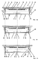
- FIGS. 1 show the first possible flow of the invention, wherein the limiters are positioned in the pick-up position. Analogously, this also applies to the positioning of the limiter after grasping the goods when it is located on the gripping device.
- FIG. 1a shows in side view a gripping device with a gripper and with two positioning actuators, which are located together with limiters in the open state on an inaccurately placed on shelves Good.
- FIG. 1b shows the gripping device with limiters, which are positioned at the edge of the inaccurate storage goods.
- Figure 1c shows the good, which is sucked on the gripper in the same position as on the pick-up position.
- FIG. 2 shows a circular good in plan view, which is in relation to the gripping device and its open delimiters in an indeterminate position at a pick-up position or gripped on the gripper (s).
- FIG. 3 shows the estate in the same location as in FIG. 2 but with limiters that have been positioned according to the invention at the edge of the goods.
- FIG. 4a shows in side view a gripping device with two carriers and with two positioning actuators, which are located together with limiters in the open state on an inaccurately placed on shelves Good.
- FIG. 4b shows the gripping device with limiters, which are positioned at the edge of the inaccurately placed goods lying on and with carriers that have traversed the goods for gripping.
- Figure 4c shows the estate in the same position, which is located lying on the carriers.
- FIG. 1a is the good 1 in the pick-up position on z.
- shelves 2 in an altitude that is known to the control system of the entire system.
- 2 mechanically supporting pins are shown as shelves.
- a shelf 2 can also serve differently designed carrier. So can serve as a shelf 2, a liquid surface on which the goods 1 floats.
- a gas cushion, in particular an air cushion, can be realized as a shelf 2.
- a combination of mechanical shelves 2 and liquid surfaces or air cushion for storing good is feasible.
- the trays 2 can serve as electrical contacts for transmitting current to the material located at least on one side in the treatment liquid.
- the coordinates of the pick-up positions of the entire production plant are known in the control system.
- the good 1 In the horizontal direction, the good 1 is shifted by an indeterminate offset 6.
- the reference line 4 or the zero point does not hit the center of the material 5.
- the gripping device 3 is in the pick-up position above the goods to be picked up 1. Their position in relation to the pick-up position ie the location of the reference line 4 and its altitude are known in the control system, because the gripping device 3 by means of z.
- As an adapter 7 with a handling device, not shown, or robot arm, which are controlled by the control system of the entire system is connected.
- At least two positioning actuators 8 are arranged on the gripping device 3, each consisting of a reversing axis 9 and a mechanically connected or integrated position measuring system 16, which are also controlled and monitored by the control system, not shown.
- On the axes 9 limiters 10 are fixed, located in the FIG. 1 a extend below the upper level of the shelves 2.
- the individual movement of each axis 9 is z. B. from an incremental position measuring system 16 with respect to a reference point or by an absolute measuring system 16 as path information individually measured.
- the limiters 10 are preferably designed so that the area in the area of the surface line is small, which has the good 1, in order to keep the possible contact area of good 1 and 10 limiters small. Suitable z. B. round, rectangular or triangular cross sections. Especially for wet processes are suitable for the limiter 10 materials with hydrophobic properties in order to avoid a transfer of liquids from the good to the limiters and vice versa.
- edge detectors 11 which can detect the edge 12 of the product 1, are arranged on the axles 9.
- edge detectors 11 which can detect the edge 12 of the product 1
- edge detectors 11 which can detect the edge 12 of the product 1
- non-contact measuring optical edge detectors z.
- Other non-contact sensors are suitable for detecting the edge 12 of the goods 1.
- Dependence on the material of the goods are z.
- the positioning actuators 8 and their axes 9 with the associated Wegmeßsytemen 16, and in combination with the attached limiters 10 and the edge detectors 11 each form a structural unit. Due to the reversing retraction and extension of the axes 9 of the positioning actuators 8, the limiters 10 are opened and closed. The opening is at least so far that when lowering the gripping device 3 at a pick-up position, the limiter 10, the good 1 do not touch even at the maximum occurring offset 6.
- the limiter 10 After lowering the gripping device 3 or after grasping the goods, the limiter 10 are positioned on the edge 12 of the goods 1. This limitation is under control of the control system of the plant.
- the completed positioning shows the FIG. 1 b .
- the edge detectors 11 next to the limiters 10 trigger during closing of the limiters in individually detecting the edge 12 via the control system or directly stopping the closing movements of the respective positioning actuators.
- the axes 9 of the positioning actuators 8 are then retracted so far that the edge 12 of the goods 1 is barely touched by the limiters 10.
- the size of the gaps 13 to be formed between the edge 12 and the generatrix of the limiter 10 facing this depends on the required positioning accuracy of the material at the target position. In practice, this gap z. B. 0.1 mm, thereby resulting in a maximum deviation of the position of the goods in the target position of also 0.1 mm.
- the dimensions of the goods have tolerances greater than the adjustable minimum gap 13.
- the invention proves the invention to be particularly advantageous because the tolerances of the dimensions of the goods 1 do not affect the positioning accuracy.
- the limiters are always positioned even with a tolerance-related Good 1, that the intended size of the gap 13 is achieved. This can be ensured even with larger tolerances of the dimensions of the goods 1 that the material center 5 is stored in the target position exactly on the target position.
- the Good 1 After being bounded in the FIGS. 1 the Good 1 first preferably grabbed by a gripper 14 by suction. Suitable z. B. vacuum grippers, suction devices and Bernoulli grippers or magnetic grippers. This situation shows the FIG. 1 c.
- the limiter 10 are in the closed position on Good 1. Therefore, a floating away of the goods during and after grasping is not possible.
- the gripper 14 or the gripping device 3 is transported by means of the handling device or robot arm together with the goods 1 to the target position. Only after dropping the limiter 10 are removed from the Good 1, ie opened. Therefore, the good 1 can not swim away during transport and especially when depositing.
- the limiters hold this in the position taken before picking them up.
- the individual occupied positions of the limiter 10, ie the axes 9 of the positioning 8 are in a position known to the control system. According to the invention these positions of the limiter 10 and their dependent on the shape of the goods number of the same and their orientation on the gripping device 3 are used to calculate the offset 6 and its direction.
- the control system calculates from the distance data determined by the distance measuring systems 16 of sufficient for the shape of the goods 1 Positionieraktoren 8, the actual position of the goods 1 or 5 Gutmitte with respect to the reference line 4, ie the offset 6 and its direction.
- the control system is then able to control the material 1 with correction of the offset 6 exactly in the target position and store it there.
- the required positioning accuracy is thus reliably achieved. This both tolerance tolerated good as well as very advantageous for different goods of different nominal dimensions within certain limits, eg. B. for solar cells with the dimensions 125 mm 2 and 156 mm 2 .
- FIG. 2 shows in plan view a round Good 1, z. B. a stored wafer whose Gutmitte 5 does not coincide with the reference line 4 of the gripping device 3.
- This reference line 4 has been controlled by the control system exactly in the desired position of the pickup position.
- the gripping device 3 is positioned with three maximum up to the pitch circle 17 open limiters 10 and attached edge detectors 11 on the Good 1. This end position 17 of the limiter 10 allows lowering, without touching the Good 1.
- FIG. 3 shows the situation with positioned at the edge 12 of the goods limiters.
- the edge 12 was detected individually by the three edge detectors 11.
- the axles 9 are retracted to different degrees into the positioning actuators 8 in accordance with the position of the goods 1 or the offset 6.
- This has the control system by means of the Wegmeßsysteme 16, which are connected to the Positionieraktoren 8 or form a structural unit, note.
- the center 5, ie the center of the circle can be calculated by the control system. This is where measured z. B. from the generatrices of the limiter 10 equal distances 15 or radii meet in one point.
- the estate of the handling device or robot arm can be stored exactly at the target position.
- a good with a different shape e.g. As a square solar cell with known dimensions, at least four Positionieraktoren 8 are required in accordance with the geometric requirements to calculate the center of gravity 5 and the direction and the amount of the offset 6 at an undetermined good.
- FIGS. 4 show a gripping device 3 with mechanical supports 18 for gripping and transporting the goods 1.
- the gripping device 3 is positioned in the pick-up position with open positioning actuators 8 and swung-out carriers 18.
- the at least two carriers 18 are z. B. pivotally or linearly movable by means of at least one actuator, not shown, arranged on the gripping device 3.
- the carrier 18 are designed in the example shown as a bracket with punctiform or large-scale support for the good.
- an elastic the material very gently bearing material, can be used on the contact surfaces of Good 1 and 18 carrier.
- the shape of the carrier 18 and its action area are dimensioned so that they can be positioned both above the largest load to be carried in the open state, as well as the smallest to be carried goods still secure capture and carry.
- FIG. 4b shows the beginning of grasping the goods or wearing.
- the carriers 18 are pivoted. They have hit the estate.
- the Positionieraktoren 8 with the limiters 10 are positioned at the edges 12 of the goods.
- the continuation of grasping and transporting shows the Figure 4c ,
- the material lies on the mechanical supports 18. It is secured against displacement during transport and when depositing in the target position by the positioned limiters 10.
Landscapes
- Manipulator (AREA)
- Container, Conveyance, Adherence, Positioning, Of Wafer (AREA)
Description
- Die Erfindung betrifft das Transportieren bzw. Handhaben von Substraten, z. B. als Wafer oder Solarzellen während der Herstellung derselben und/oder bei der späteren Verarbeitung dieser Güter. Diese bestehen z. B. aus dünnen Siliziumscheiben. Von daher sind sie sehr bruchempfindlich. Deshalb müssen sie beim Aufnehmen bzw. Ergreifen und Ablegen, oder allgemein beim Handhaben sehr stressfrei, d. h. ohne wesentliche Krafteinwirkung behandelt werden. Hinzu kommt, dass die bekannten Anlagen oder Prozesskammern zur Behandlung dieser Güter in der Regel ein sehr präzises Positionieren der Substrate an den Ablagestellen erfordern.
- Die Druckschrift
DE 202 12 107 U1 beschreibt einen Greifer für Bauteile, deren Lage beim Aufnehmen zunächst undefiniert ist. Nach dem Ergreifen des Gutes wird mittels mindestens einer Kamera, die an der Greifvorrichtung installiert ist, die Lage des Gutes am Greifer bestimmt und zwar während der Transportbewegung zur nächsten Position, d. h. zur Zielposition. Eine Steuereinrichtung wertet die Daten der Kamera aus, wodurch das präzise Ablegen des Gutes am Zielort mittels der Anlagensteuerung und der dort gespeicherten Positionsdaten des Zieles möglich ist. Zum Ergreifen des Gutes werden die bekannten Vakuumgreifer, Saugvorrichtungen und vorzugsweise Bernoulli-Greifer beschrieben. Diese haben jedoch den Nachteil, dass besonders beim Aufnehmen und dem vertikalen Ablegen des Gutes ein horizontales Verschieben bzw. Auswandern oder Wegschwimmen desselben erfolgen kann. Dieses Wegschwimmen ist mindestens beim Ablegen nicht mehr korrigierbar. Die Folge ist ein ungenaues Ablegen auf der Zielposition. - Die Druckschrift
DE 197 55 694 C2 beschreibt einen Bernoulli-Greifer zum Transport von Wafern. Zur Vermeidung des Auswanderns, d. h. zur Sicherheit dienen am Umfang des Gutes verteilt angeordnete verstellbare Führungsarme mit zylinderförmigen Enden, die über die Oberfläche des Greifers und damit über das Gut hinausragen. Die Führungsarme werden an die Geometrie und Maßtoleranzen des zu greifenden Gutes angepasst. Die zylinderförmigen Enden begrenzen das Gut, wodurch ein unzulässiges radiales Auswandern vermieden wird. - Der Träger bzw. Greifer ist an einem Manipulator befestigt, der ihn an eine Abholposition bringt, an der das Gut aufgenommen werden soll und an eine andere Stelle führt, an der das Gut wieder abgelegt werden soll. Dies setzt jedoch voraus, dass sich das abzuholende Gut in einer, dem Steuerungssystem bekannten Lage der jeweiligen Position befindet. Andernfalls käme es durch einen möglichen Zusammenstoß zu einer Beschädigung des Gutes und/oder zu einer anschließend ungenauen Ablage in der Zielposition.
- Während der Behandlung eines Gutes in einer Anlagenposition, d. h. in einer Behandlungsstation besteht in der Regel stets die Gefahr des Veränderns der Lage des Gutes. Weil das Steuerungssystem des Manipulators dann von der tatsächlichen Lage des abzuholenden Gutes keine Kenntnis hat, kann es drauf auch nicht reagieren.
- Aufgabe der Erfindung ist es, eine Greifvorrichtung bereitzustellen, insbesondere für bruchempfindliche Güter wie siliziumbasierte Wafer oder Solarzellen, die innerhalb von bestimmten Abmessungen beliebige Größen, d. h. unterschiedliche Nennmaße aufweisen können, die von einer Abholposition ungenau liegendes Gut stressfrei aufnehmen, in horizontaler oder geneigter Lage transportieren und in einer Zielposition exakt positioniert und unversehrt ablegen kann.
- Gelöst wird die Aufgabe durch die Vorrichtung gemäß Patentanspruch 1 und durch das Verfahren gemäß Patentanspruch 19. Die Unteransprüche beschreiben vorteilhafte Ausführungen der Erfindung.
- Die Erfindung besteht aus mindestens einer Greifvorrichtung, die z. B. an einem Handhabungsgerät oder einem Roboterarm einer Produktionsanlage befestigt ist oder sind. Die jeweilige dreidimensionale Position des Handhabungsgerätes oder des Roboterarmes einschließlich der Ausrichtung der Greifvorrichtung sind im Steuerungssystem der Produktionsanlage zur Nass- oder Trockenbehandlung des Gutes bekannt. Damit ist die exakte Position und Lage der Greifvorrichtung bekannt. In der Regel sind auch die exakten Positionen bzw. die Koordinaten der Ablagestellen der gesamten Anlage im Steuerungssystem bekannt, an denen von der Greifvorrichtung Güter aufzunehmen bzw. abzulegen sind. Nicht genau bekannt ist jedoch die Lage der Güter auf den Ablagestellen der jeweiligen Anlagenposition. Das Gut kann sich z. B. während einer Trockenbehandlung oder Nassbehandlung unbemerkt verschrieben. Insbesondere wenn das Gut ein geringes Gewicht aufweist, wie z. B. eine Solarzelle, dann muss mit einer horizontalen Verschiebung während der Behandlung gerechnet werden. Eine Verschiebung im Bereich von weniger als einem Millimeter kann schon für den nachfolgenden Prozess unzulässig groß sein.
- Diese Verschiebung wird durch die erfindungsgemäße Greifvorrichtung jeweils für den nachfolgenden Prozess korrigiert. Hierzu dienen Positionieraktoren, die an der Greifvorrichtung angeordnet sind und vom Steuerungssystem der gesamten Anlage ebenfalls gesteuert und überwacht werden. Die Positionieraktoren haben reversierend bewegte Achsen mit jeweils daran befestigten Sensoren als Kantendetektoren und mindestens je einem Begrenzer. Damit sind die dreidimensionale Lage der Positionieraktoren, der Kantendetektoren und der Begrenzer auf der Greifvorrichtung, die Richtungen der Achsbewegungen der Positionieraktoren und ihre momentane Stellung, d. h. ihre Weginformationen im Steuerungssystem bekannt. Mit diesen Daten berechnet das Steuerungssystem die Koordinaten, die die Greifvorrichtung beim Ablegen des Gutes in der Zielposition einnehmen muss. Als Bezugspunkt oder Nullpunkt soll für die Beschreibung der Erfindung nachfolgend die Mitte der Greifvorrichtung definiert werden. Jedoch könnte dafür auch jede andere Lage auf der Greifvorrichtung festgelegt werden.
- An der Unterseite der Greifvorrichtung ist in einer ersten Ausführung der Erfindung ein das Gut erfassender Greifer bevorzugt so angeordnet, dass sich das Zentrum des Greifers mit dem Bezugspunkt bzw. Nullpunkt auf einer gemeinsamen vertikalen Linie befinden. Als Greifer können z. B. die bekannten Vakuumgreifer, Saugvorrichtungen oder Bernoulli-Greifer verwendet werden. Des Weiteren ermöglicht die Erfindung in einer weiteren Ausführung auch die Verwendung von mechanischen Greifern als mindestens zwei Träger, die das Gut vom Rand her unterfahren und dieses durch vertikalen Hub tragend ergreifen und im Ziel absenkend ablegen. Bei ferromagnetischen Gütern sind auch magnetische Greifer verwendbar.
- Der Greifer bzw. die Träger nehmen das zu greifende Gut an der Abholposition auf, transportieren es in horizontaler oder geneigter Lage und legen es an der Zielposition ab. Diese Positionen bzw. die Koordinaten aller Ablagestellen der Produktionsanlage sind im Steuerungssystem sehr genau bekannt. Desgleichen ist auch die momentane räumliche Bezugslinie bzw. der Nullpunkt der Greifvorrichtung, die von dem Handhabungsgerät oder einem Roboterarm steuernd bewegt wird, im Steuerungssystem fortlaufend bekannt. Unbekannt ist jedoch die genaue Lage des Gutes in der Abholposition. Hier muss stets mit einem Versatz, der eine maximale Größe erreichen kann, gerechnet werden.
- Bei einem ersten möglichen Ablauf der Erfindung werden in der Abholposition vor dem Ergreifen des Gutes von der Greifvorrichtung am Umfang des abzuholenden Gutes verteilte mechanische Begrenzer derart positioniert, dass sich das Gut, ohne geklemmt zu werden, lateral nicht mehr verschieben kann. Hierzu werden die Begrenzer, die sich auf den Achsen der Positionieraktoren befinden, mittels dieser von einer maximal ausgefahrenen bzw. geöffneten Stellung, d. h. von einer Endposition in Richtung des Bezugspunktes, d. h. zum Rand des Gutes schließend bewegt. In räumlicher Nähe jedes Begrenzers und zusammen mit diesen an den Achsen der Positionieraktoren befestigt, befindet sich ein Kantendetektor, der das Gut bevorzugt berührungslos detektiert, z. B. eine Reflexlichtschranke mit Hintergrundausblendung oder eine Einweglichtschranke.
- Beim Einfahren bzw. Schließen der Begrenzer mittels der Achsen der Positionieraktoren erkennt jeder Kantendetektor individuell die äußere Kante des auf der Abholposition liegenden Gutes. Bei Erreichen der Kante wird die individuelle Bewegung jedes Positionieraktors sofort angehalten. Der Begrenzer und der jeweils zugehörige Kantendetektor sind voneinander beabstandet so auf der Achse des Positionieraktors angeordnet, dass auch bei einem möglichen Nachlauf des Positionieraktors nach dem Erkennen der Kante des Gutes dieses von dem jeweiligen Begrenzer aus seiner ungenauen Lage nicht verschoben wird. Der Begrenzer stoppt unmittelbar vor der zu begrenzenden Kante des Gutes.
- In Abwandlung der beschriebenen ersten Abläufe erlaubt die Erfindung auch das Ergreifen des in ungenauer Lage befindlichen Gutes mittels des Greifers oder der Träger, ohne die Begrenzer an der Kante zuvor positioniert zu haben. Der möglicherweise zusätzliche Lagefehler des Gutes durch ein Wegschwimmen oder Verschieben beim Aufnehmen wird in Kauf genommen. Erst nach dem Ergreifen des Gutes, d. h. während des gesamten Transportes bis spätestens zum Zeitpunkt des Beginns der Bewegung zum Ablegen werden die Begrenzer an der Kante des Gutes so positioniert, wie es oben beschrieben wurde. Das Ablegen in der Zielposition erfolgt dann mit den in Position befindlichen Begrenzern, wodurch ein Wegschwimmen oder Verschieben des Gutes verhindert wird. Somit kann auch bei diesem Ablauf das Gut in der Zielposition sehr genau abgelegt werden.
- In Abhängigkeit von der Form des Gutes werden mindestens zwei Positionieraktoren auf der Greifvorrichtung angeordnet. So sind zum Beispiel bei einem kreisrunden Gut drei Positionieraktoren und Begrenzer erforderlich, um das in unbekannter Lage befindliche Gut eindeutig zu detektieren und zu begrenzen. Bei dem ersten beschriebenen Ablauf der Erfindung wird das Gut vom Greifer erst nach der bevorzugt gleichzeitigen Positionierung aller Begrenzer gegriffen. Wegen der erfindungsgemäß positionierten Begrenzer verändert sich die unbestimmte Lage des Gutes nach dem Ergreifen auch am Greifer nicht. Wie oben beschrieben, können diese drei Begrenzer auch erst nach dem Ergreifen mittels des Greifers bzw. Trägers an der Kante des Gutes positioniert werden. In diesem Falle kann sich die Lage des in der Abholposition befindlichen Gutes am Greifer durch ein Wegschwimmen oder Verschieben nochmals unbestimmt verändern, was jedoch die Positioniergenauigkeit in der Zielposition nicht beeinflusst.
- Das Positionieren der Begrenzer an dem Rand des Gutes erfolgt mittels der Positionieraktoren und deren linear oder schwenkend verlagerbaren Achsen. Die Verlagerungen gehen von Endpositionen aus, die als Referenzpunkte im Steuerungssystem der Anlage bekannt sind. Die dabei individuell zurückgelegten Wege der Begrenzer zur mechanischen Begrenzung des Gutes werden zugleich von einem Wegmeßsystem als Wegdaten erfasst und an das Steuerungssystem weitergeleitet. Das Wegmeßsystem kann integraler Bestandteil des Positionieraktors sein. Es kann auch ein externer Sensor sein, der die Bewegung der Achse des Positionieraktors misst. Die Wegdaten, gemessen z. B. von bestimmten Referenzpunkten der Positionieraktoren, lassen eine eindeutige Bestimmung der Größe und der Richtung des Versatzes des Gutes zu, wenn entsprechend der Form des Gutes genügend viele Begrenzer am Umfang des Gutes verteilt positioniert worden sind.
- Mit Hilfe des berechneten Versatzes und dessen Richtung kann dann das Gut auf der Zielposition exakt vom Handhabungsgerät oder einem Roboterarm abgelegt werden. Die Soll-Koordinaten der Zielposition oder der Bezugspunkt der Greifvorrichtung werden hierzu im Steuerungssystem um den Versatz vorzeichengerecht korrigiert.
- Bei einem Gut mit der Form eines Vieleckes ist die Anzahl der Positionieraktoren so groß zu wählen, dass aus den Wegdaten der Positionieraktoren in Bezug zum Bezugspunkt bzw. Nullpunkt die Lage und Ausrichtung des Gutes eindeutig berechenbar ist. Eine über diese theoretische Anzahl hinausgehende Anzahl von Positionieraktoren erhöht die Genauigkeit der Positionierungen der Greifvorrichtung. So können bei einem quadratischen Gut, z. B. bei einer Solarzelle vier oder mehr Positionieraktoren verwendet werden.
- Die Lage des Gutes auf der Abholposition bestimmt die Positionen der Begrenzer an der Greifvorrichtung, die bis zum Ablegen auf der Zielposition nicht verändert werden. Bei einem unbegrenzten Ergreifen des Gutes von der Abholposition bestimmt die dann eingenommene Lage des Gutes am Greifer bzw. Träger die Positionen der Begrenzer an der Greifvorrichtung, die bis zum Ablegen auf der Zielposition nicht verändert werden. Erst nach dem Ablegen werden die Begrenzer wieder ausgefahren bzw. geöffnet. Dies stellt erfindungsgemäß sicher, dass das Gut während des Ablegens nicht wegschwimmen oder sich verschieben kann. Die einmal eingegrenzte Lage des Gutes bleibt bis zum endgültigen Ablegen sehr genau erhalten. Damit vermeidet die Erfindung sehr vorteilhaft den ansonsten störenden Nachteil besonders der Vakuumgreifer, Saugvorrichtungen und Bernoulli-Greifer, nämlich das unbestimmte Wegschwimmen beim Ablegen des Gutes. Gleiches gilt für Träger, die das Gut in schräger Lage transportieren.
- Die Erfindung wird nachfolgend an Hand der schematischen und nicht maßstäblichen
Figuren 1 bis 4 detailliert beschrieben. - Die
Figuren 1 zeigen den ersten möglichen Ablauf der Erfindung, wobei die Begrenzer in der Abholposition positioniert werden. Sinngemäß gilt dies auch für das Positionieren der Begrenzer erst nach dem Ergreifen des Gutes, wenn es sich an der Greifvorrichtung befindet. -
Figur 1a zeigt in der Seitenansicht eine Greifvorrichtung mit einem Greifer und mit zwei Positionieraktoren, die sich zusammen mit Begrenzern im geöffneten Zustand über einem ungenau auf Ablagen abgelegten Gut befinden.Figur 1b zeigt die Greifvorrichtung mit Begrenzern, die an dem Rand des ungenau auf Ablagen liegenden Gutes positioniert sind.Figur 1c zeigt das Gut, das sich am Greifer angesaugt in der selben Lage befindet, wie auf der Abholposition. -
Figur 2 zeigt ein kreisrundes Gut in der Draufsicht, das sich in Bezug zur Greifvorrichtung und deren geöffneten Begrenzern in einer unbestimmten Lage auf einer Abholposition oder gegriffen am Greifer bzw. den Trägern befindet. -
Figur 3 zeigt das Gut in der selben Lage wie inFigur 2 , jedoch mit Begrenzern, die erfindungsgemäß am Rand des Gutes positioniert worden sind. -
Figur 4a zeigt in der Seitenansicht eine Greifvorrichtung mit zwei Trägern und mit zwei Positionieraktoren, die sich zusammen mit Begrenzern im geöffneten Zustand über einem ungenau auf Ablagen abgelegten Gut befinden.Figur 4b zeigt die Greifvorrichtung mit Begrenzern, die an dem Rand des ungenau auf Ablagen liegenden Gutes positioniert sind und mit Trägern, die das Gut zum Ergreifen unterfahren haben.Figur 4c zeigt das Gut in der selben Lage, das sich gegriffen auf den Trägern liegend befindet. - In
Figur 1a liegt das Gut 1 in der Abholposition auf z. B. Ablagen 2 in einer Höhenlage, die dem Steuerungssystem der gesamten Anlage bekannt ist. Beispielhaft sind als Ablagen 2 mechanisch tragende Pins dargestellt. Als Ablage 2 können auch anders gestaltete Träger dienen. So kann als Ablage 2 auch eine Flüssigkeitsoberfläche dienen, auf der das Gut 1 schwimmt. Auch ein Gaspolster, insbesondere ein Luftpolster, ist als Ablage 2 realisierbar. Auch eine Kombination von mechanischen Ablagen 2 und Flüssigkeitsoberflächen oder Luftpolster zur Ablage von Gut ist realisierbar. Bei einer elektrolytischen Behandlung können dabei zum Beispiel die Ablagen 2 als elektrische Kontakte zur Stromübertragung auf das mindestens einseitig in der Behandlungsflüssigkeit befindliche Gut dienen. - Die Koordinaten der Abholpositionen der gesamten Produktionsanlage sind im Steuerungssystem bekannt. In der horizontalen Richtung ist das Gut 1 um einen unbestimmten Versatz 6 verschoben. Die hier in der Mitte der Greifvorrichtung 3 liegende Bezugslinie 4 bzw. der Nullpunkt trifft nicht die Gutmitte 5. Zwischen der Bezugslinie 4 und der Gutmitte 5 besteht ein Versatz 6, dessen Größe und Richtung im Steuerungssystem der Anlage nicht bekannt ist. Die Greifvorrichtung 3 befindet sich in der Abholposition über dem abzuholenden Gut 1. Ihre Lage in Bezug zur Abholposition d. h. die Lage der Bezugslinie 4 und ihre Höhenlage sind im Steuerungssystem bekannt, weil die Greifvorrichtung 3 mittels z. B. eines Adapters 7 mit einem nicht dargestellten Handhabungsgerät oder Roboterarm, die vom Steuerungssystem der gesamten Anlage gesteuert werden, verbunden ist.
- An der Greifvorrichtung 3 sind mindestens zwei Positionieraktoren 8 angeordnet, jeweils bestehend aus einer reversierenden Achse 9 und einem damit mechanisch verbundenen oder integrieren Wegmeßsystem 16, die ebenfalls vom nicht dargestellten Steuerungssystem gesteuert und überwacht werden. An den Achsen 9 sind Begrenzer 10 befestigt, die sich in der
Figur 1 a bis unterhalb der oberen Ebene der Ablagen 2 erstrecken. Die individuelle Bewegung jeder Achse 9 wird z. B. von einem inkrementalen Wegmeßsystem 16 in Bezug zu einem Referenzpunkt oder von einem absoluten Wegmeßsystem 16 als Weginformation individuell gemessen. - Die Begrenzer 10 sind bevorzugt so gestaltet, dass die Fläche im Bereich der Mantellinie klein ist, die zum Gut 1 weist, um die mögliche Berührungsfläche von Gut 1 und Begrenzer 10 klein zu halten. Geeignet sind z. B. runde, rechteckige oder dreieckige Querschnitte. Insbesondere für Nassprozesse eignen sich für die Begrenzer 10 Werkstoffe mit hydrophoben Eigenschaften, um eine Übertragung von Flüssigkeiten vom Gut zu den Begrenzern und umgekehrt zu vermeiden.
- In der Nähe der Begrenzer 10 sind jeweils an den Achsen 9 des Weiteren Kantendetektoren 11 angeordnet, die die Kante 12 des Gutes 1 detektieren können. Hierzu dienen bevorzugt berührungslos messende optische Kantendetektoren, z. B. Reflexlichtschranken mit Hintergrundausblendung oder Einweglichtschranken. Auch andere berührungslos messende Sensoren sind zur Erfassung der Kante 12 des Gutes 1 geeignet. In Abhängigkeit vom Werkstoff des Gutes sind dies z. B. induktive und kapazitive Kantendetektoren oder Ultraschallsensoren.
- Die Positionieraktoren 8 und ihre Achsen 9 mit den zugehörigen Wegmeßsytemen 16, sowie die in Kombination der daran befestigten Begrenzer 10 und der Kantendetektoren 11 bilden jeweils eine konstruktive Baueinheit. Durch das reversierende Ein- und Ausfahren der Achsen 9 der Positionieraktoren 8 werden die Begrenzer 10 geöffnet und geschlossen. Das Öffnen geschieht mindestens soweit, dass beim Absenken der Greifvorrichtung 3 an einer Abholposition die Begrenzer 10 das Gut 1 auch bei dem maximal vorkommenden Versatz 6 nicht berühren.
- Nach dem Absenken der Greifvorrichtung 3 oder nach dem Ergreifen des Gutes werden die Begrenzer 10 an der Kante 12 des Gutes 1 positioniert. Dieses Begrenzen erfolgt unter Kontrolle des Steuerungssystems der Anlage. Die erfolgte Positionierung zeigt die
Figur 1 b. Die Kantendetektoren 11 neben den Begrenzern 10 lösen während des Schließens der Begrenzer beim individuellen Detektieren der Kante 12 über das Steuerungssystem oder direkt das Anhalten der Schließbewegungen der jeweiligen Positionieraktoren aus. Die Achsen 9 der Positionieraktoren 8 sind dann soweit eingefahren, dass die Kante 12 des Gutes 1 von den Begrenzern 10 gerade noch nicht berührt wird. Die Größe der dabei zu bildende Spalten 13 zwischen der Kante 12 und der dieser gegenüber stehenden Mantellinie des Begrenzers 10 richtet sich nach der erforderlichen Positioniergenauigkeit des Gutes auf der Zielposition. In der Praxis kann dieser Spalt z. B. 0,1 mm betragen, wodurch sich dadurch eine maximale Abweichung der Lage des Gutes in der Zielposition von ebenfalls 0,1 mm ergibt. - In der Praxis weisen die Abmessungen der Güter Toleranzen auf, die größer als der einstellbare minimale Spalt 13 ist. Hier erweist sich die Erfindung als besonders vorteilhaft, weil die Toleranzen der Abmessungen des Gutes 1 die Positioniergenauigkeit nicht beeinflussen. Die Begrenzer werden auch bei einem toleranzbehafteten Gut 1 stets so positioniert, dass die vorgesehene Größe des Spaltes 13 erreicht wird. Damit kann auch bei größeren Toleranzen der Abmessungen des Gutes 1 sichergestellt werden, dass die Gutmitte 5 in der Zielposition genau auf der Sollposition abgelegt wird.
- Dies wäre mit einem Greifer nach dem Stand der Technik mit fest eingestellten seitlichen Begrenzern nicht möglich, denn diese müssen so weit eingestellt werden, dass beim Ergreifen das Gut mit der größten positiven Toleranz der Abmessungen und mit dem größten Versatz auf den Ablagen von den Begrenzern nicht getroffen, d. h. nicht beschädigt werden kann. Entsprechend sehr ungenau wird dann besonders das Gut mit den größten negativen Toleranzen der Abmessungen auf der Zielposition abgelegt.
- Nach dem Begrenzen wird in den
Figuren 1 das Gut 1 zunächst von einem Greifer 14 bevorzugt durch Ansaugen gegriffen. Geeignet sind z. B. Vakuumgreifer, Saugvorrichtungen und Bernoulli-Greifer oder magnetische Greifer. Diese Situation zeigt dieFigur 1 c. Die Begrenzer 10 befinden sich in der geschlossenen Position am Gut 1. Daher ist ein Wegschwimmen des Gutes beim und nach dem Ergreifen nicht möglich. Anschließend wird der Greifer 14 bzw. die Greifvorrichtung 3 mittels des Handhabungsgerätes oder Roboterarmes zusammen mit dem Gut 1 zur Zielposition transportiert. Erst nach dem Ablegen werden die Begrenzer 10 vom Gut 1 entfernt, d. h. geöffnet. Von daher kann das Gut 1 auch beim Transport und besonders beim Ablegen nicht wegschwimmen. Die Begrenzer halten dieses in der vor dem Aufnehmen von ihnen eingenommenen Lage. Die dabei individuell eingenommenen Stellungen der Begrenzer 10, d. h. der Achsen 9 der Positionieraktoren 8 sind in einer dem Steuerungssystem bekannten Lage. Erfindungsgemäß werden diese Stellungen der Begrenzer 10 sowie ihre von der Form des Gutes abhängige Anzahl derselben und ihre Ausrichtung auf der Greifvorrichtung 3 zur Berechnung des Versatzes 6 und dessen Richtung genutzt. Das Steuerungssystem berechnet aus den von den Wegmeßsystemen 16 ermittelten Wegdaten der für die Form des Gutes 1 ausreichend vielen Positionieraktoren 8 die tatsächliche Lage des Gutes 1 oder die Gutmitte 5 in Bezug zur Bezugslinie 4, d. h. den Versatz 6 und dessen Richtung. Das Steuerungssystem ist dann in der Lage, das Gut 1 unter Korrektur des Versatzes 6 exakt in die Zielposition zu steuern und es dort abzulegen. Die erforderliche Positioniergenauigkeit wird damit zuverlässig erreicht. Dies sowohl bei toleranzbehaftetem Gut als auch sehr vorteilhaft bei unterschiedlichen Gütern verschiedener Nennmaße innerhalb von bestimmten Grenzen, z. B. für Solarzellen mit den Abmessungen 125 mm2 und 156 mm2. - Die
Figur 2 zeigt in der Draufsicht ein rundes Gut 1, z. B. einen abgelegten Wafer, dessen Gutmitte 5 sich mit dem Bezugslinie 4 der Greifvorrichtung 3 nicht deckt. Diese Bezugslinie 4 ist vom Steuerungssystem exakt in die Sollposition der Abholposition gesteuert worden. Es besteht ein Versatz 6. Die Greifvorrichtung 3 ist mit drei maximal bis zum Teilkreis 17 geöffneten Begrenzern 10 und daran befestigten Kantendetektoren 11 über dem Gut 1 positioniert. Diese Endposition 17 der Begrenzer 10 ermöglicht das Absenken, ohne dabei das Gut 1 zu berühren. - Die
Figur 3 zeigt die Situation mit an der Kante 12 des Gutes positionierten Begrenzern. Die Kante 12 wurde von den drei Kantendetektoren 11 individuell erfasst. Die Achsen 9 sind entsprechend der Lage des Gutes 1 bzw. des Versatzes 6 unterschiedlich weit in die Positionieraktoren 8 eingefahren. Hierüber hat das Steuerungssystem mittels der Wegmeßsysteme 16, die mit den Positionieraktoren 8 verbunden sind oder eine konstruktive Baueinheit bilden, Kenntnis. Mit der bekannten Zusatzinformation, dass es sich in diesem Beispiel um ein kreisrundes Gut handelt, kann die Gutmitte 5, d. h. der Mittelpunkt des Kreises vom Steuerungssystem berechnet werden. Dieser liegt dort, wo sich gemessen z. B. von den Mantellinien der Begrenzer 10 gleich lange Strecken 15 bzw. Radien in einem Punkte treffen. Damit und weil ein Wegschwimmen des Gutes durch die Begrenzer ausgeschlossen worden ist, kann das Gut vom Handhabungsgerät oder Roboterarm an der Zielposition exakt abgelegt werden. Bei einem Gut mit einer anderen Form, z. B. eine quadratische Solarzelle mit bekannten Abmessungen, sind entsprechend der geometrischen Erfordernisse mindestens vier Positionieraktoren 8 erforderlich, um bei einem unbestimmt liegenden Gut die Gutmitte 5 sowie die Richtung und den Betrag des Versatzes 6 zu berechnen. - Die
Figuren 4 zeigen eine Greifvorrichtung 3 mit mechanischen Trägern 18 zum Ergreifen und Transportieren des Gutes 1. In derFigur 1a ist die Greifvorrichtung 3 in der Abholposition mit geöffneten Positionieraktoren 8 und ausgeschwenkten Trägern 18 positioniert. Die mindestens zwei Träger 18 sind z. B. schwenkbar oder linear beweglich mittels mindestens eines nicht dargestellten Aktors an der Greifvorrichtung 3 angeordnet. Die Träger 18 sind in dem dargestellten Beispiel als Bügel mit punktförmiger oder großflächiger Auflage für das Gut gestaltet. Auch ein elastischer, das Gut sehr schonend tragender Werkstoff, kann an den Berührungsflächen von Gut 1 und Träger 18 verwendet werden. Die Form der Träger 18 sowie ihr Aktionsbereich sind so dimensioniert, dass Sie sowohl über dem größten zu tragenden Gut im geöffneten Zustand positioniert werden können, als auch das kleinste zu tragende Gut noch sicher erfassen und tragen können. - Die
Figur 4b zeigt den Beginn des Ergreifens des Gutes bzw. des Tragens. Die Träger 18 sind eingeschwenkt. Sie haben das Gut unterfahren. Die Positionieraktoren 8 mit den Begrenzern 10 sind an den Kanten 12 des Gutes positioniert. Die Fortsetzung des Ergreifens und Transportierens zeigt dieFigur 4c . Das Gut liegt auf den mechanischen Trägern 18. Es wird gegen ein Verschieben während des Transportes und beim Ablegen in der Zielposition durch die positionierten Begrenzer 10 gesichert. -
- 1
- Gut, Substrat, Wafer, Solarzelle
- 2
- Ablage
- 3
- Greifvorrichtung
- 4
- Bezugslinie, Nullpunkt
- 5
- Gutmitte
- 6
- Versatz
- 7
- Adapter
- 8
- Positionieraktor
- 9
- Achse
- 10
- Begrenzer
- 11
- Kantendetektor, Sensor
- 12
- Kante des Gutes
- 13
- Spalt
- 14
- Greifer
- 15
- Strecke, Radius
- 16
- Wegmeßsystem
- 17
- Teilkreis, Endposition
- 18
- Träger
Claims (16)
- Vorrichtung zum Transport in bevorzugt horizontaler oder geneigter Lage von Gut (1) wie bruchempfindlichen Substraten als Wafer oder Solarzellen in gesteuerten Produktionsanlagen von einer Ablagestelle eines Nass- oder Trockenprozesses zur nächsten mittels einer Greifvorrichtung (3), mit mindestens einem Greifer (14) oder Träger (18), der oder die sich an einem Handhabungsgerät oder an einem Roboterarm befinden, gekennzeichnet je Greifer (14) oder Träger (18) durch mindestens zwei Positionieraktoren (8) zur kontrollierten gemeinsamen Verlagerung je eines Kantendetektors (11), mit mindestens einem Begrenzer (10).
- Vorrichtung nach Patentanspruch 1, gekennzeichnet durch ein Wegmeßsystem (16), das mit der Achse (9) des Positionieraktors (8) und damit auch mit dem Kantendetektor (11), und mindestens mit einem Begrenzer (10) zu deren kontrollierten gemeinsamen Verlagerung mechanisch verbunden ist.
- Vorrichtung nach Patentanspruch 1 oder 2, gekennzeichnet durch ein Wegmeßsystem (16), als inkrementales Wegmeßsystem mit einem Referenzpunkt an einer Endposition (17) oder als absolutes Wegmeßsystem.
- Vorrichtung nach einem der Patentansprüche 1 bis 3, gekennzeichnet durch einen Positionieraktor (8) als pneumatischen, elektrischen, hydraulischen oder magnetischen Linearantrieb oder Schwenkantrieb.
- Vorrichtung nach einem der Patentansprüche 1 bis 4, gekennzeichnet durch Kantendetektoren (11) zur Erfassung der Kante (12) des Gutes als optische, magnetische, induktive, kapazitive Sensoren oder Ultraschallsensoren.
- Vorrichtung nach einem der Patentansprüche 1 bis 5, gekennzeichnet durch eine Justierung der oder des Begrenzer(s) (10) und des Kantendetektors (11) auf der Achse (9) derart, dass nach dem Einfahren aller Begrenzer (10) das Gut (1) an dessen Kante (12) nicht geklemmt wird.
- Vorrichtung nach einem der Patentansprüche 1 bis 6, gekennzeichnet durch mindestens zwei Träger (18) als punktförmig tragende Bügel oder großflächige Auflagen zum Ergreifen des Gutes durch Unterfahren und Ausheben desselben.
- Vorrichtung nach einem der Patentansprüche 1 bis 7, gekennzeichnet durch eine Anordnung und Verteilung der Positionieraktoren (8) und ihre Ausrichtungen auf der Greifvorrichtung (3) derart, dass bei eingefahrenen Begrenzern (10) das begrenzte Gut nicht wegschwimmen oder verschoben werden kann.
- Verfahren zum Transport in bevorzugt horizontaler oder geneigter Lage von Gut (1) wie bruchempfindlichen Substraten als Wafer oder Solarzellen in gesteuerten Produktionsanlagen von einer Ablagestelle eines Nass- oder Trockenprozesses zur nächsten mittels einer Greifvorrichtung (3), mit mindestens einem Greifer (14) oder Träger (18), der oder die sich an einem Handhabungsgerät oder an einem Roboterarm befinden, unter Verwendung der Vorrichtung nach Anspruch 1, gekennzeichnet durch die Verfahrensschritte:a) Positionieren der Greifvorrichtung (3) mit ausgefahrenen Begrenzern (10) und Trägern (18) über dem aufzunehmenden Gut (1), das sich in einer toleranzbehafteten Lage in der Abholposition befindet; undb) Ergreifen des Gutes (1) mittels des Greifers (14) oder der Träger (18); undc) Transport des Gutes zur Zielposition; undf) Absenken der Greifvorrichtung (3) und Ablegen des Gutes auf Ablagen (2) der Zielposition; undg) Öffnen der Begrenzer (10) nach dem Ablegen; wobeih) die Begrenzer (10) durch eine Schließbewegung mittels individueller Positionieraktoren (8) an der Kante (12) des in unbekannter Lage befindlichen Gutes positioniert werden, und dass dabei aus den mittels Wegmeßsystemen (16) individuell gemessenen Positionen der Begrenzer, die dem Steuerungssystem der Anlage mitgeteilt werden, der Versatz (6) und die Richtung des Versatzes berechnet wird, wobei dieses Positionieren der Begrenzer (10) zwischen den Verfahrensschritten a) und b) oder b) und c) oder während des Verfahrensschrittes c) eingefügt wird.
- Verfahren nach Patentanspruch 9, dadurch gekennzeichnet, dass das Ergreifen des Gutes (1) saugend durch Unterdruck oder durch Unterfahren mittels mindestens zwei Träger (18) und Ausheben erfolgt.
- Verfahren nach Patentanspruch 9 oder 10, dadurch gekennzeichnet, dass mittels des berechneten Versatzes (6) und dessen Richtung die Sollkoordinaten der Zielpositionen derart vom Steuerungssystem vorzeichengerecht korrigiert werden, dass das Gut an der Zielposition vom Handhabungsgerät oder Roboterarm korrekt abgelegt wird.
- Verfahren nach einem der Patentansprüche 9 bis 11, dadurch gekennzeichnet, dass beim Schließen der Begrenzer (10) die mit ihnen verbundenen Kantendetektoren (11) bei Erreichen der Kante (12) des Gutes diese erkennen und die Schließbewegungen der Positionieraktoren (8) individuell mittels des Steuerungssystems oder direkt gesteuert so anhalten, dass einerseits das Gut nicht geklemmt wird und andererseits eine zulässige Breite des Spaltes (13) nicht überschritten wird.
- Verfahren nach einem der Patentansprüche 9 bis 12, dadurch gekennzeichnet, dass mindestens beim Ablegen ein Wegschwimmen oder Verschieben des Gutes durch die positionierten Begrenzer (10) verhindert wird.
- Verfahren nach einem der Patentansprüche 9 bis 13, dadurch gekennzeichnet, dass die Wegmeßsysteme (16) die gemessenen Wegdaten in Bezug zu jeweiligen Referenzpunkten oder Endpositionen als Messwerte dem Steuerungssystem zur Berechnung des Versatzes (6) und dessen Richtung mitteilt.
- Verfahren nach einem der Patentansprüche 9 bis 14, dadurch gekennzeichnet, dass Gut mit unterschiedlichen Formen oder Vielecken durch eine dafür ausreichend große Anzahl von Begrenzern (10) begrenzt wird, die eine eindeutige Berechnung des Versatzes und dessen Richtung ermöglicht.
- Verfahren nach einem der Patentansprüche 9 bis 15, dadurch gekennzeichnet, dass unterschiedlich große Nennmaße der Güter durch entsprechend weite lineare oder schwenkende Bewegungen der Achsen (9) und/oder der Träger (18) gehandhabt werden.
Applications Claiming Priority (2)
| Application Number | Priority Date | Filing Date | Title |
|---|---|---|---|
| DE102008045255A DE102008045255A1 (de) | 2008-09-01 | 2008-09-01 | Vorrichtung und Verfahren zum Transportieren von Substraten |
| PCT/EP2009/005531 WO2010022843A1 (de) | 2008-09-01 | 2009-07-30 | Vorrichtung und verfahren zum transportieren von substraten |
Publications (2)
| Publication Number | Publication Date |
|---|---|
| EP2183772A1 EP2183772A1 (de) | 2010-05-12 |
| EP2183772B1 true EP2183772B1 (de) | 2011-02-09 |
Family
ID=41186146
Family Applications (1)
| Application Number | Title | Priority Date | Filing Date |
|---|---|---|---|
| EP09777553A Not-in-force EP2183772B1 (de) | 2008-09-01 | 2009-07-30 | Vorrichtung und verfahren zum transportieren von substraten |
Country Status (4)
| Country | Link |
|---|---|
| EP (1) | EP2183772B1 (de) |
| AT (1) | ATE498200T1 (de) |
| DE (2) | DE102008045255A1 (de) |
| WO (1) | WO2010022843A1 (de) |
Families Citing this family (1)
| Publication number | Priority date | Publication date | Assignee | Title |
|---|---|---|---|---|
| CN117855132B (zh) * | 2024-03-07 | 2024-05-03 | 泓浒(苏州)半导体科技有限公司 | 基于伯努利原理的晶圆传送控制方法及传送控制系统 |
Family Cites Families (8)
| Publication number | Priority date | Publication date | Assignee | Title |
|---|---|---|---|---|
| DE3915038A1 (de) * | 1989-05-08 | 1990-11-22 | Balzers Hochvakuum | Halte- und transportvorrichtung fuer eine scheibe |
| DE4037204C2 (de) * | 1990-11-22 | 1994-06-09 | Fraunhofer Ges Forschung | Greifersystem, insbesondere zur Reinraumanwendung |
| DE19755694C2 (de) | 1997-12-16 | 2000-05-31 | Sez Semiconduct Equip Zubehoer | Handhabungsvorrichtung für dünne, scheibenförmige Gegenstände |
| US6113165A (en) * | 1998-10-02 | 2000-09-05 | Taiwan Semiconductor Manufacturing Co., Ltd. | Self-sensing wafer holder and method of using |
| DE20212107U1 (de) | 2002-08-06 | 2003-03-06 | Manz Automation AG, 72768 Reutlingen | Greifvorrichtung |
| TWI270952B (en) * | 2003-02-20 | 2007-01-11 | Applied Materials Inc | Methods and apparatus for determining a position of a substrate relative to a support stage |
| US8016541B2 (en) * | 2003-09-10 | 2011-09-13 | Brooks Automation, Inc. | Substrate handling system for aligning and orienting substrates during a transfer operation |
| JP4866782B2 (ja) * | 2007-04-27 | 2012-02-01 | 富士フイルム株式会社 | 基板クランプ機構及び描画システム |
-
2008
- 2008-09-01 DE DE102008045255A patent/DE102008045255A1/de not_active Withdrawn
-
2009
- 2009-07-30 WO PCT/EP2009/005531 patent/WO2010022843A1/de not_active Ceased
- 2009-07-30 EP EP09777553A patent/EP2183772B1/de not_active Not-in-force
- 2009-07-30 AT AT09777553T patent/ATE498200T1/de active
- 2009-07-30 DE DE502009000367T patent/DE502009000367D1/de active Active
Also Published As
| Publication number | Publication date |
|---|---|
| WO2010022843A1 (de) | 2010-03-04 |
| DE102008045255A1 (de) | 2010-03-04 |
| ATE498200T1 (de) | 2011-02-15 |
| DE502009000367D1 (de) | 2011-03-24 |
| EP2183772A1 (de) | 2010-05-12 |
Similar Documents
| Publication | Publication Date | Title |
|---|---|---|
| DE69420616T2 (de) | Aufnahme- und Fördereinheit für Stapel von Zuschnitten | |
| EP2195267B2 (de) | Verfahren zum entstapeln von plattenförmigen teilen | |
| DE102013106819B4 (de) | Verfahren zum robotergestützten Stapeln von Gegenständen | |
| DE102012019841B4 (de) | Verfahren und Vorrichtung für das Umsetzen großflächiger Platten in extremer Übergröße | |
| EP3758900B1 (de) | Anlage zur bearbeitung von flächigen werkstücken | |
| DE102014008444A1 (de) | Vorrichtung zum automatisierten Entnehmen von in einem Behälter angeordneten Werkstücken | |
| EP2909117A2 (de) | Vorrichtung und verfahren zum schnellen versetzen von platten | |
| DE102020127981B3 (de) | Wendevorrichtung zum Handhaben empfindlicher Substrate bei der Belichtung von zweidimensionalen Strukturen auf beiden Substratoberflächen | |
| DE102012019839A1 (de) | Verfahren und Vorrichtung für das Befördern großflächiger Platten in extremer Übergröße | |
| DE102015210842B3 (de) | Vorrichtung und Verfahren zum Greifen, Vereinzeln, Transportieren und/oder Ablegen von verschlossenen und/oder unverschlossenen Petrischalen | |
| EP3680922B1 (de) | Verfahren und positioniersystem zur herstellung von transformatorkernen | |
| DE102019115571B4 (de) | Schnelles Abtransportieren von geschnittenen Teilen aus einer Verarbeitungsanlage | |
| DE202012009644U1 (de) | Vorrichtung für das Befördern großflächiger Platten in extremer Übergröße | |
| WO2014121875A1 (de) | Vorrichtung und verfahren zum palettieren von stapeln | |
| EP3595827A1 (de) | Zentriervorrichtung | |
| DE202012010085U1 (de) | Vorrichtung zum schnellen Versetzen von Platten | |
| EP3509973A1 (de) | Robotische transportvorrichtung zum transportieren von kleinteilen und mit der robotischen vorrichtung durchführbares verfahren | |
| DE202012009650U1 (de) | Vorrichtung für das Umsetzen großflächiger Platten in extremer Übergröße | |
| WO2010022843A1 (de) | Vorrichtung und verfahren zum transportieren von substraten | |
| EP3630421B1 (de) | Verfahren zur ausrichtung zweier werkstücke zur ausbildung einer fügeverbindung und manipulator | |
| DE102013022533B3 (de) | Verfahren zum robotergestützten Stapeln von Gegenständen | |
| EP2321845B1 (de) | Vorrichtung und verfahren zum handhaben von substraten | |
| DE112017006520T5 (de) | Übergabesystem und verfahren zu dessen betrieb | |
| DE102022125564B3 (de) | Verfahren zum Handhaben von Gegenständen und Handhabungsanlage | |
| EP3093879B1 (de) | Endeffector eines waferhandlingsystems sowie waferhandlingsystem |
Legal Events
| Date | Code | Title | Description |
|---|---|---|---|
| PUAI | Public reference made under article 153(3) epc to a published international application that has entered the european phase |
Free format text: ORIGINAL CODE: 0009012 |
|
| 17P | Request for examination filed |
Effective date: 20100317 |
|
| AK | Designated contracting states |
Kind code of ref document: A1 Designated state(s): AT BE BG CH CY CZ DE DK EE ES FI FR GB GR HR HU IE IS IT LI LT LU LV MC MK MT NL NO PL PT RO SE SI SK SM TR |
|
| AX | Request for extension of the european patent |
Extension state: AL BA RS |
|
| GRAP | Despatch of communication of intention to grant a patent |
Free format text: ORIGINAL CODE: EPIDOSNIGR1 |
|
| GRAS | Grant fee paid |
Free format text: ORIGINAL CODE: EPIDOSNIGR3 |
|
| GRAA | (expected) grant |
Free format text: ORIGINAL CODE: 0009210 |
|
| AK | Designated contracting states |
Kind code of ref document: B1 Designated state(s): AT BE BG CH CY CZ DE DK EE ES FI FR GB GR HR HU IE IS IT LI LT LU LV MC MK MT NL NO PL PT RO SE SI SK SM TR |
|
| REG | Reference to a national code |
Ref country code: GB Ref legal event code: FG4D Free format text: NOT ENGLISH |
|
| REG | Reference to a national code |
Ref country code: CH Ref legal event code: EP |
|
| REG | Reference to a national code |
Ref country code: IE Ref legal event code: FG4D Free format text: LANGUAGE OF EP DOCUMENT: GERMAN |
|
| REF | Corresponds to: |
Ref document number: 502009000367 Country of ref document: DE Date of ref document: 20110324 Kind code of ref document: P |
|
| REG | Reference to a national code |
Ref country code: DE Ref legal event code: R096 Ref document number: 502009000367 Country of ref document: DE Effective date: 20110324 |
|
| REG | Reference to a national code |
Ref country code: NL Ref legal event code: VDEP Effective date: 20110209 |
|
| LTIE | Lt: invalidation of european patent or patent extension |
Effective date: 20110209 |
|
| PG25 | Lapsed in a contracting state [announced via postgrant information from national office to epo] |
Ref country code: LV Free format text: LAPSE BECAUSE OF FAILURE TO SUBMIT A TRANSLATION OF THE DESCRIPTION OR TO PAY THE FEE WITHIN THE PRESCRIBED TIME-LIMIT Effective date: 20110209 Ref country code: SE Free format text: LAPSE BECAUSE OF FAILURE TO SUBMIT A TRANSLATION OF THE DESCRIPTION OR TO PAY THE FEE WITHIN THE PRESCRIBED TIME-LIMIT Effective date: 20110209 Ref country code: PT Free format text: LAPSE BECAUSE OF FAILURE TO SUBMIT A TRANSLATION OF THE DESCRIPTION OR TO PAY THE FEE WITHIN THE PRESCRIBED TIME-LIMIT Effective date: 20110609 Ref country code: ES Free format text: LAPSE BECAUSE OF FAILURE TO SUBMIT A TRANSLATION OF THE DESCRIPTION OR TO PAY THE FEE WITHIN THE PRESCRIBED TIME-LIMIT Effective date: 20110520 Ref country code: GR Free format text: LAPSE BECAUSE OF FAILURE TO SUBMIT A TRANSLATION OF THE DESCRIPTION OR TO PAY THE FEE WITHIN THE PRESCRIBED TIME-LIMIT Effective date: 20110510 Ref country code: LT Free format text: LAPSE BECAUSE OF FAILURE TO SUBMIT A TRANSLATION OF THE DESCRIPTION OR TO PAY THE FEE WITHIN THE PRESCRIBED TIME-LIMIT Effective date: 20110209 Ref country code: HR Free format text: LAPSE BECAUSE OF FAILURE TO SUBMIT A TRANSLATION OF THE DESCRIPTION OR TO PAY THE FEE WITHIN THE PRESCRIBED TIME-LIMIT Effective date: 20110209 Ref country code: NO Free format text: LAPSE BECAUSE OF FAILURE TO SUBMIT A TRANSLATION OF THE DESCRIPTION OR TO PAY THE FEE WITHIN THE PRESCRIBED TIME-LIMIT Effective date: 20110509 |
|
| PG25 | Lapsed in a contracting state [announced via postgrant information from national office to epo] |
Ref country code: FI Free format text: LAPSE BECAUSE OF FAILURE TO SUBMIT A TRANSLATION OF THE DESCRIPTION OR TO PAY THE FEE WITHIN THE PRESCRIBED TIME-LIMIT Effective date: 20110209 Ref country code: BG Free format text: LAPSE BECAUSE OF FAILURE TO SUBMIT A TRANSLATION OF THE DESCRIPTION OR TO PAY THE FEE WITHIN THE PRESCRIBED TIME-LIMIT Effective date: 20110509 Ref country code: PL Free format text: LAPSE BECAUSE OF FAILURE TO SUBMIT A TRANSLATION OF THE DESCRIPTION OR TO PAY THE FEE WITHIN THE PRESCRIBED TIME-LIMIT Effective date: 20110209 Ref country code: NL Free format text: LAPSE BECAUSE OF FAILURE TO SUBMIT A TRANSLATION OF THE DESCRIPTION OR TO PAY THE FEE WITHIN THE PRESCRIBED TIME-LIMIT Effective date: 20110209 Ref country code: CY Free format text: LAPSE BECAUSE OF FAILURE TO SUBMIT A TRANSLATION OF THE DESCRIPTION OR TO PAY THE FEE WITHIN THE PRESCRIBED TIME-LIMIT Effective date: 20110209 Ref country code: SI Free format text: LAPSE BECAUSE OF FAILURE TO SUBMIT A TRANSLATION OF THE DESCRIPTION OR TO PAY THE FEE WITHIN THE PRESCRIBED TIME-LIMIT Effective date: 20110209 |
|
| REG | Reference to a national code |
Ref country code: IE Ref legal event code: FD4D |
|
| PG25 | Lapsed in a contracting state [announced via postgrant information from national office to epo] |
Ref country code: DK Free format text: LAPSE BECAUSE OF FAILURE TO SUBMIT A TRANSLATION OF THE DESCRIPTION OR TO PAY THE FEE WITHIN THE PRESCRIBED TIME-LIMIT Effective date: 20110209 Ref country code: IE Free format text: LAPSE BECAUSE OF FAILURE TO SUBMIT A TRANSLATION OF THE DESCRIPTION OR TO PAY THE FEE WITHIN THE PRESCRIBED TIME-LIMIT Effective date: 20110209 Ref country code: EE Free format text: LAPSE BECAUSE OF FAILURE TO SUBMIT A TRANSLATION OF THE DESCRIPTION OR TO PAY THE FEE WITHIN THE PRESCRIBED TIME-LIMIT Effective date: 20110209 |
|
| PG25 | Lapsed in a contracting state [announced via postgrant information from national office to epo] |
Ref country code: CZ Free format text: LAPSE BECAUSE OF FAILURE TO SUBMIT A TRANSLATION OF THE DESCRIPTION OR TO PAY THE FEE WITHIN THE PRESCRIBED TIME-LIMIT Effective date: 20110209 Ref country code: SK Free format text: LAPSE BECAUSE OF FAILURE TO SUBMIT A TRANSLATION OF THE DESCRIPTION OR TO PAY THE FEE WITHIN THE PRESCRIBED TIME-LIMIT Effective date: 20110209 Ref country code: RO Free format text: LAPSE BECAUSE OF FAILURE TO SUBMIT A TRANSLATION OF THE DESCRIPTION OR TO PAY THE FEE WITHIN THE PRESCRIBED TIME-LIMIT Effective date: 20110209 |
|
| PLBE | No opposition filed within time limit |
Free format text: ORIGINAL CODE: 0009261 |
|
| STAA | Information on the status of an ep patent application or granted ep patent |
Free format text: STATUS: NO OPPOSITION FILED WITHIN TIME LIMIT |
|
| PG25 | Lapsed in a contracting state [announced via postgrant information from national office to epo] |
Ref country code: MT Free format text: LAPSE BECAUSE OF FAILURE TO SUBMIT A TRANSLATION OF THE DESCRIPTION OR TO PAY THE FEE WITHIN THE PRESCRIBED TIME-LIMIT Effective date: 20110209 |
|
| 26N | No opposition filed |
Effective date: 20111110 |
|
| BERE | Be: lapsed |
Owner name: RENA G.M.B.H. Effective date: 20110731 |
|
| PG25 | Lapsed in a contracting state [announced via postgrant information from national office to epo] |
Ref country code: MC Free format text: LAPSE BECAUSE OF NON-PAYMENT OF DUE FEES Effective date: 20110731 |
|
| REG | Reference to a national code |
Ref country code: DE Ref legal event code: R097 Ref document number: 502009000367 Country of ref document: DE Effective date: 20111110 |
|
| PG25 | Lapsed in a contracting state [announced via postgrant information from national office to epo] |
Ref country code: BE Free format text: LAPSE BECAUSE OF NON-PAYMENT OF DUE FEES Effective date: 20110731 |
|
| PG25 | Lapsed in a contracting state [announced via postgrant information from national office to epo] |
Ref country code: IT Free format text: LAPSE BECAUSE OF FAILURE TO SUBMIT A TRANSLATION OF THE DESCRIPTION OR TO PAY THE FEE WITHIN THE PRESCRIBED TIME-LIMIT Effective date: 20110209 |
|
| PG25 | Lapsed in a contracting state [announced via postgrant information from national office to epo] |
Ref country code: MK Free format text: LAPSE BECAUSE OF FAILURE TO SUBMIT A TRANSLATION OF THE DESCRIPTION OR TO PAY THE FEE WITHIN THE PRESCRIBED TIME-LIMIT Effective date: 20110209 |
|
| PG25 | Lapsed in a contracting state [announced via postgrant information from national office to epo] |
Ref country code: SM Free format text: LAPSE BECAUSE OF FAILURE TO SUBMIT A TRANSLATION OF THE DESCRIPTION OR TO PAY THE FEE WITHIN THE PRESCRIBED TIME-LIMIT Effective date: 20110209 |
|
| PG25 | Lapsed in a contracting state [announced via postgrant information from national office to epo] |
Ref country code: LU Free format text: LAPSE BECAUSE OF NON-PAYMENT OF DUE FEES Effective date: 20110730 |
|
| PG25 | Lapsed in a contracting state [announced via postgrant information from national office to epo] |
Ref country code: IS Free format text: LAPSE BECAUSE OF FAILURE TO SUBMIT A TRANSLATION OF THE DESCRIPTION OR TO PAY THE FEE WITHIN THE PRESCRIBED TIME-LIMIT Effective date: 20110209 |
|
| PG25 | Lapsed in a contracting state [announced via postgrant information from national office to epo] |
Ref country code: TR Free format text: LAPSE BECAUSE OF FAILURE TO SUBMIT A TRANSLATION OF THE DESCRIPTION OR TO PAY THE FEE WITHIN THE PRESCRIBED TIME-LIMIT Effective date: 20110209 |
|
| PG25 | Lapsed in a contracting state [announced via postgrant information from national office to epo] |
Ref country code: HU Free format text: LAPSE BECAUSE OF FAILURE TO SUBMIT A TRANSLATION OF THE DESCRIPTION OR TO PAY THE FEE WITHIN THE PRESCRIBED TIME-LIMIT Effective date: 20110209 |
|
| PGFP | Annual fee paid to national office [announced via postgrant information from national office to epo] |
Ref country code: DE Payment date: 20130724 Year of fee payment: 5 Ref country code: CH Payment date: 20130723 Year of fee payment: 5 |
|
| PGFP | Annual fee paid to national office [announced via postgrant information from national office to epo] |
Ref country code: FR Payment date: 20130719 Year of fee payment: 5 Ref country code: GB Payment date: 20130723 Year of fee payment: 5 |
|
| REG | Reference to a national code |
Ref country code: DE Ref legal event code: R119 Ref document number: 502009000367 Country of ref document: DE |
|
| REG | Reference to a national code |
Ref country code: CH Ref legal event code: PL |
|
| GBPC | Gb: european patent ceased through non-payment of renewal fee |
Effective date: 20140730 |
|
| REG | Reference to a national code |
Ref country code: DE Ref legal event code: R119 Ref document number: 502009000367 Country of ref document: DE Effective date: 20150203 |
|
| REG | Reference to a national code |
Ref country code: FR Ref legal event code: ST Effective date: 20150331 |
|
| PG25 | Lapsed in a contracting state [announced via postgrant information from national office to epo] |
Ref country code: DE Free format text: LAPSE BECAUSE OF NON-PAYMENT OF DUE FEES Effective date: 20150203 Ref country code: CH Free format text: LAPSE BECAUSE OF NON-PAYMENT OF DUE FEES Effective date: 20140731 Ref country code: LI Free format text: LAPSE BECAUSE OF NON-PAYMENT OF DUE FEES Effective date: 20140731 |
|
| PG25 | Lapsed in a contracting state [announced via postgrant information from national office to epo] |
Ref country code: FR Free format text: LAPSE BECAUSE OF NON-PAYMENT OF DUE FEES Effective date: 20140731 Ref country code: GB Free format text: LAPSE BECAUSE OF NON-PAYMENT OF DUE FEES Effective date: 20140730 |
|
| REG | Reference to a national code |
Ref country code: AT Ref legal event code: MM01 Ref document number: 498200 Country of ref document: AT Kind code of ref document: T Effective date: 20140730 |
|
| PG25 | Lapsed in a contracting state [announced via postgrant information from national office to epo] |
Ref country code: AT Free format text: LAPSE BECAUSE OF NON-PAYMENT OF DUE FEES Effective date: 20140730 |