EP2183161B1 - Self-energizing gripper for strapping machine - Google Patents
Self-energizing gripper for strapping machine Download PDFInfo
- Publication number
- EP2183161B1 EP2183161B1 EP08797747A EP08797747A EP2183161B1 EP 2183161 B1 EP2183161 B1 EP 2183161B1 EP 08797747 A EP08797747 A EP 08797747A EP 08797747 A EP08797747 A EP 08797747A EP 2183161 B1 EP2183161 B1 EP 2183161B1
- Authority
- EP
- European Patent Office
- Prior art keywords
- gripper
- gripping element
- links
- strap
- accordance
- Prior art date
- Legal status (The legal status is an assumption and is not a legal conclusion. Google has not performed a legal analysis and makes no representation as to the accuracy of the status listed.)
- Active
Links
- 239000000463 material Substances 0.000 claims abstract description 10
- 238000007789 sealing Methods 0.000 description 3
- 230000002411 adverse Effects 0.000 description 2
- 238000012986 modification Methods 0.000 description 2
- 230000004048 modification Effects 0.000 description 2
- 229910000831 Steel Inorganic materials 0.000 description 1
- 230000001154 acute effect Effects 0.000 description 1
- 238000012423 maintenance Methods 0.000 description 1
- 239000002184 metal Substances 0.000 description 1
- 230000035945 sensitivity Effects 0.000 description 1
- 239000010959 steel Substances 0.000 description 1
Images

Classifications
-
- B—PERFORMING OPERATIONS; TRANSPORTING
- B65—CONVEYING; PACKING; STORING; HANDLING THIN OR FILAMENTARY MATERIAL
- B65B—MACHINES, APPARATUS OR DEVICES FOR, OR METHODS OF, PACKAGING ARTICLES OR MATERIALS; UNPACKING
- B65B13/00—Bundling articles
- B65B13/18—Details of, or auxiliary devices used in, bundling machines or bundling tools
- B65B13/24—Securing ends of binding material
- B65B13/32—Securing ends of binding material by welding, soldering, or heat-sealing; by applying adhesive
- B65B13/322—Friction welding
-
- B—PERFORMING OPERATIONS; TRANSPORTING
- B65—CONVEYING; PACKING; STORING; HANDLING THIN OR FILAMENTARY MATERIAL
- B65B—MACHINES, APPARATUS OR DEVICES FOR, OR METHODS OF, PACKAGING ARTICLES OR MATERIALS; UNPACKING
- B65B13/00—Bundling articles
- B65B13/18—Details of, or auxiliary devices used in, bundling machines or bundling tools
- B65B13/24—Securing ends of binding material
- B65B13/32—Securing ends of binding material by welding, soldering, or heat-sealing; by applying adhesive
Definitions
- This invention pertains to a gripper for a strapping machine. More particularly, this invention pertains to a gripper for use in the strapping head of a strapping machine for plastic strapping material.
- Strapping machines are well-known in the art. There are two principle types of strapping machines, manual and automatic, table-top or freestanding machines. Strapping machines are typically designed for use with either plastic or metal (steel) strapping. These machines position, tension and seal strap around a load to bundle or secure the load.
- a typical strapping machine includes a frame-like support for the overall machine, a working area to, for example, support a load, a feed head to feed strap around the load and to retract strap prior to tensioning, a chute through which the strap is fed around the load, a strapping head to secure the strap to itself and one or more dispensers for dispensing the strap material to the strapping head.
- the strapping head serves a number of functions. First, it clamps or grips a free end of the strap (end grip) as it returns to the strapping head. Next, it clamps or grips a trailing end of the strap following retraction and during tensioning of the strap (tension grip). Then, it grips the strap again (both courses of strap) on the opposite or inside of the strap loop (loop gripper), as it severs the sealed strap from the feed or dispenser side (to permit removing the strapped load from the machine) and seals the overlapping courses of strapping together.
- One or more of the grippers may be of the self actuating type. That is, rather than relying on an applied (e.g., cylinder-provided) force, the movement of the strap urges a pivoting gripper element into greater (higher force) contact with the strap.
- These known self-energizing grippers use a single pivot, lobed element with an asymmetric curved gripping surface to capture the strap between the gripping surface and a clamping surface.
- the gripping surface is curved, the area of contact between the gripper and the strap is small. This can result in the strap being deformed, which can affect refeeding the strap, as during a next strapping cycle.
- a self energizing gripper that is not adversely effected by variations in strap gauge.
- such a self-energizing gripper will not fail to grip with an overly thick strap.
- such a gripper does not rely on a small contact are to secure the strap.
- such a gripper does not deform the strap as it grips the strap.
- a self-energizing gripper is used in a strapping machine having a rigid surface along which a strapping material traverses and against which the strapping material is clamped.
- the gripper includes first and second links mounted at respective first ends to the strapping machine for pivotal movement and a gripping element pivotally mounted to respective second ends of each the first and second links.
- the gripping element includes a substantially planar gripping element surface.
- the first and second links are mounted to the gripping element for pivotal movement of the gripping element along an arcuate path toward and away from the rigid surface.
- the gripping element surface remains parallel as the gripping element moves along the arc between an open gripper position and a closed gripper position.
- the self energizing gripper is not adversely effected by variations in strap gauge and as such will not fail to grip an overly thick or overly thin strap.
- the gripper uses a relatively larger contact area to secure the strap. Because the gripper has a flat contact or gripper surface, it does not deform the strap as it grips the strap.
- a present gripper includes a biasing element operably connected to the links to urge the gripping element to the closed gripper position.
- the links are mounted parallel to one another and the gripping element surface is substantially planar.
- a cam element can be mounted to one of the links such that contact with the cam urges the gripping element to the open gripper position.
- the parallelogram link arrangement is configured such that an axis of each of the links forms an angle with the rigid surface and movement of the gripping element along the arcuate path toward and away from the rigid surface is through an angle of less than 90 degrees and maintains that gripping element surface parallel to the rigid surface.
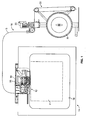
- FIG. 1 is a front view of an overhead strapping machine having a self-energizing gripper embodying with the principles of the present invention
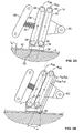
- FIGS. 2A and 2B are an enlarged partial views of the self energizing gripper in the closed and open gripper states, respectively;
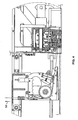
- FIG. 3 is an illustration of the strapper showing the gripper in an open state
- FIG. 4 is an illustration of the strapper showing the gripper in a closed state.
- the strapper 10 includes, generally, a frame 14, a strap chute 16, a sealing head or module 18, a feed or drive head (or module) 20 and a strap dispenser 22.
- the dispenser 22 and feed head 20 can be separately located (generally nearby), to facilitate maintenance on the dispenser 22 (e.g., reloading strap reels R) and the feed head 20 as needed.
- Packages P to be strapped are positioned within the chute 16. Packages can be of any size that fits within the chute 16.
- the sealer module 18 has a number of grippers. For example, an end grip 24 clamps the free end F of the strap S as it returns to the strapping head 18. A tension grip 26 clamps the trailing end T of the strap following retraction and during tensioning of the strap, and a loop grip 28 clamps both courses of strap on the opposite or inside of the strap loop L, as the sealed strap loop L is severed from the feed or dispenser 22 side and the seal (sealing the overlapping courses of strapping together) is formed.
- grippers For example, an end grip 24 clamps the free end F of the strap S as it returns to the strapping head 18.
- a tension grip 26 clamps the trailing end T of the strap following retraction and during tensioning of the strap, and a loop grip 28 clamps both courses of strap on the opposite or inside of the strap loop L, as the sealed strap loop L is severed from the feed or dispenser 22 side and the seal (sealing the overlapping courses of strapping together) is formed.
- Some of the grippers are actuated by a mechanical or electromechanical element to exert the full force necessary to clamp the strap.
- a cylinder or cam element 30 can exert a force on a gripper element (for example loop grip 28) that clamps down onto the strap S.
- Other grippers are of the self-energizing type in which the tension force of the strap S urges the gripper tighter.
- the present self-energizing gripper 12 uses a gripping element 34 that has a relatively large, flat or relatively flat gripping head surface 36.
- the element 34 is mounted by multiple (preferably two) pivot links 38, 40, for pivotal movement, into and out of engagement with the strap S, which is passed between the gripping element 34 and a platen or anvil 42.
- the platen 42 is a rigid, flat or substantially flat surface along which the strap S traverses toward the sealing head 18.
- the pivot links 38, 40 are fixed (but mounted for pivotal movement) at respective pivot locations 44, 46 (to the strapper 10) and are pivotally mounted to the gripping element 34 at their opposite ends as indicated at 48, 50.
- the links 38, 40 are parallel (e.g., A 38 and A 40 are parallel) and equal length (e.g., d 38 and d 40 between respective pivots 44/48 and 46/50) and as such, although the gripping element 34 moves in a pivotal or arcuate motion, the gripping head surface 36 remains parallel to the platen 42 surface as the gripping element 34 moves or pivots between the open and closed gripper positions ( FIGS. 3 and 4 , respectively).
- This parallelogram link configuration provides means for mounting the element 34 to the strapping machine 10 such that the element 34 pivots into and out of contact with the strap S, but the contact surface 36 remains parallel to the strap S to maximize the contact area (indicated generally at 52).
- the angle ⁇ through which the links 38, 40 (and thus the element 34) pivot is acute, i.e., less than 90 degrees.
- the contact area 52 between the gripping head surface 36 and the strap S is substantially larger than known single pivot grippers. Accordingly, there is less opportunity for the gripper 12 to deform the strap S when the gripping head surface 36 is in contact with the strap S. Moreover, the flat gripping head surface 36 is substantially less sensitive to variations in strap thickness or gauge t s , in part because of the flat surface 36, but also because of the increased distance d 38 , d 40 between the fixed pivot axes 44, 46 and the gripping head surface 36. This also provides a relatively large contact angle ⁇ .
- the present gripping head surface 36 is textured or roughened, as by forming a diamond-pattern in the surface 36.
- the gripping element 34 is urged toward contact with the strap S by a biasing element, such as the illustrated coil spring 54.
- the spring 54 is intended to urge the gripping head element 34 into contact with the strap S, rather than to provide a substantial contact force between the gripping element 34 and the strap S.
- the spring 54 is mounted to the machine 10 at a location (indicated at 56) that is fixed relative to the moving gripper 12.
- the spring 54 contacts one of the links (an outboard link 38) on a side of the link 38 to urge the element 34 into contact with the strap S and platen 42.
- a release function for the gripper 12 is provided in two ways.
- the opposite link (the inboard link 40) includes a cam element 60 mounted thereto. The cam 60 is disposed such that a force applied to the cam 60 (as indicated by the arrow at 62) will urge the element 34 (and the links 38, 40) to pivot to open the gripper 12.
- movement of the gripping element 34 to open the gripper 12 is against the spring 54 force.
- Contact on and movement of the cam 60 can be effected by relative movement of the cam 60 and a release element, or movement of the strapping head and or tensioning assembly such that the cam 60 contacts a (relatively) fixed element (see surface 64 in FIG. 3 ) on the strapping machine 10.
Abstract
Description
- This invention pertains to a gripper for a strapping machine. More particularly, this invention pertains to a gripper for use in the strapping head of a strapping machine for plastic strapping material.
- Strapping machines are well-known in the art. There are two principle types of strapping machines, manual and automatic, table-top or freestanding machines. Strapping machines are typically designed for use with either plastic or metal (steel) strapping. These machines position, tension and seal strap around a load to bundle or secure the load.
- A typical strapping machine includes a frame-like support for the overall machine, a working area to, for example, support a load, a feed head to feed strap around the load and to retract strap prior to tensioning, a chute through which the strap is fed around the load, a strapping head to secure the strap to itself and one or more dispensers for dispensing the strap material to the strapping head.
- In a plastic strapping machine, the strapping head serves a number of functions. First, it clamps or grips a free end of the strap (end grip) as it returns to the strapping head. Next, it clamps or grips a trailing end of the strap following retraction and during tensioning of the strap (tension grip). Then, it grips the strap again (both courses of strap) on the opposite or inside of the strap loop (loop gripper), as it severs the sealed strap from the feed or dispenser side (to permit removing the strapped load from the machine) and seals the overlapping courses of strapping together.
- One or more of the grippers may be of the self actuating type. That is, rather than relying on an applied (e.g., cylinder-provided) force, the movement of the strap urges a pivoting gripper element into greater (higher force) contact with the strap. These known self-energizing grippers use a single pivot, lobed element with an asymmetric curved gripping surface to capture the strap between the gripping surface and a clamping surface.
- Although these self energizing grippers function well to secure the strap, there are drawbacks. First, because the gripper element pivot is close to the gripping surface, the gripper is sensitive to strap thickness. For example, a thicker strap will increase the contact angle such that the gripper may not properly self energize. This requires the pivot location (axis) to be adjusted for different strap gauges.
- Moreover, because the gripping surface is curved, the area of contact between the gripper and the strap is small. This can result in the strap being deformed, which can affect refeeding the strap, as during a next strapping cycle.
- Efforts to increase the contact area between the gripping surface and the strap include increasing the area of the clamping surface, as by forming a curve in the surface, however, it has been observed that such efforts show the same drawbacks as that of the conventional gripper, that is, sensitivity to strap thickness and strap deformation.
- Accordingly, there exists a need for a self energizing gripper that is not adversely effected by variations in strap gauge. Desirably, such a self-energizing gripper will not fail to grip with an overly thick strap. More desirably, such a gripper does not rely on a small contact are to secure the strap. More desirably still, such a gripper does not deform the strap as it grips the strap.
- A self-energizing gripper is used in a strapping machine having a rigid surface along which a strapping material traverses and against which the strapping material is clamped. The gripper includes first and second links mounted at respective first ends to the strapping machine for pivotal movement and a gripping element pivotally mounted to respective second ends of each the first and second links. The gripping element includes a substantially planar gripping element surface.
- The first and second links are mounted to the gripping element for pivotal movement of the gripping element along an arcuate path toward and away from the rigid surface. The gripping element surface remains parallel as the gripping element moves along the arc between an open gripper position and a closed gripper position.
- The self energizing gripper is not adversely effected by variations in strap gauge and as such will not fail to grip an overly thick or overly thin strap. The gripper uses a relatively larger contact area to secure the strap. Because the gripper has a flat contact or gripper surface, it does not deform the strap as it grips the strap.
- A present gripper includes a biasing element operably connected to the links to urge the gripping element to the closed gripper position. Preferably, the links are mounted parallel to one another and the gripping element surface is substantially planar. A cam element can be mounted to one of the links such that contact with the cam urges the gripping element to the open gripper position.
- The parallelogram link arrangement is configured such that an axis of each of the links forms an angle with the rigid surface and movement of the gripping element along the arcuate path toward and away from the rigid surface is through an angle of less than 90 degrees and maintains that gripping element surface parallel to the rigid surface.
- These and other features and advantages of the present invention will be apparent from the following detailed description, in conjunction with the appended claims.
- The benefits and advantages of the present invention will become more readily apparent to those of ordinary skill in the relevant art after reviewing the following detailed description and accompanying drawings, wherein:
-
FIG. 1 is a front view of an overhead strapping machine having a self-energizing gripper embodying with the principles of the present invention; -
FIGS. 2A and 2B are an enlarged partial views of the self energizing gripper in the closed and open gripper states, respectively; -
FIG. 3 is an illustration of the strapper showing the gripper in an open state; and -
FIG. 4 is an illustration of the strapper showing the gripper in a closed state. - While the present invention is susceptible of embodiment in various forms, there is shown in the drawings and will hereinafter be described a presently preferred embodiment with the understanding that the present disclosure is to be considered an exemplification of the invention and is not intended to limit the invention to the specific embodiment illustrated.
- It should be further understood that the title of this section of this specification, namely, "Detailed Description Of The Invention", relates to a requirement of the United States Patent Office, and does not imply, nor should be inferred to limit the subject matter disclosed herein.
- Referring now to the figures and in particular to
FIG. 1 there is illustrated a strappingmachine 10 having a self-energizinggripper 12 embodying the principles of the present invention. Thestrapper 10 includes, generally, aframe 14, astrap chute 16, a sealing head ormodule 18, a feed or drive head (or module) 20 and astrap dispenser 22. As illustrated, thedispenser 22 andfeed head 20 can be separately located (generally nearby), to facilitate maintenance on the dispenser 22 (e.g., reloading strap reels R) and thefeed head 20 as needed. Packages P to be strapped are positioned within thechute 16. Packages can be of any size that fits within thechute 16. - The
sealer module 18 has a number of grippers. For example, an end grip 24 clamps the free end F of the strap S as it returns to the strappinghead 18. Atension grip 26 clamps the trailing end T of the strap following retraction and during tensioning of the strap, and aloop grip 28 clamps both courses of strap on the opposite or inside of the strap loop L, as the sealed strap loop L is severed from the feed or dispenser 22 side and the seal (sealing the overlapping courses of strapping together) is formed. - Some of the grippers are actuated by a mechanical or electromechanical element to exert the full force necessary to clamp the strap. For example, a cylinder or
cam element 30 can exert a force on a gripper element (for example loop grip 28) that clamps down onto the strap S. Other grippers are of the self-energizing type in which the tension force of the strap S urges the gripper tighter. - Referring to
FIGS. 2A and 2B , the present self-energizing gripper 12 (shown in the closed and open states, respectively), uses agripping element 34 that has a relatively large, flat or relatively flat grippinghead surface 36. Theelement 34 is mounted by multiple (preferably two)pivot links gripping element 34 and a platen oranvil 42. Theplaten 42 is a rigid, flat or substantially flat surface along which the strap S traverses toward the sealinghead 18. - The
pivot links respective pivot locations 44, 46 (to the strapper 10) and are pivotally mounted to thegripping element 34 at their opposite ends as indicated at 48, 50. Thelinks respective pivots 44/48 and 46/50) and as such, although thegripping element 34 moves in a pivotal or arcuate motion, the grippinghead surface 36 remains parallel to theplaten 42 surface as the grippingelement 34 moves or pivots between the open and closed gripper positions (FIGS. 3 and4 , respectively). This parallelogram link configuration provides means for mounting theelement 34 to the strappingmachine 10 such that theelement 34 pivots into and out of contact with the strap S, but thecontact surface 36 remains parallel to the strap S to maximize the contact area (indicated generally at 52). The angle α through which thelinks 38, 40 (and thus the element 34) pivot is acute, i.e., less than 90 degrees. - Because the gripping
head surface 36 is flat or relatively flat, thecontact area 52 between thegripping head surface 36 and the strap S is substantially larger than known single pivot grippers. Accordingly, there is less opportunity for thegripper 12 to deform the strap S when the grippinghead surface 36 is in contact with the strap S. Moreover, the flatgripping head surface 36 is substantially less sensitive to variations in strap thickness or gauge ts, in part because of theflat surface 36, but also because of the increased distance d38, d40 between the fixed pivot axes 44, 46 and thegripping head surface 36. This also provides a relatively large contact angle β. The presentgripping head surface 36 is textured or roughened, as by forming a diamond-pattern in thesurface 36. - The gripping
element 34 is urged toward contact with the strap S by a biasing element, such as the illustratedcoil spring 54. Thespring 54 is intended to urge the grippinghead element 34 into contact with the strap S, rather than to provide a substantial contact force between thegripping element 34 and the strap S. Thespring 54 is mounted to themachine 10 at a location (indicated at 56) that is fixed relative to the movinggripper 12. Thespring 54 contacts one of the links (an outboard link 38) on a side of thelink 38 to urge theelement 34 into contact with the strap S andplaten 42. - In a
present gripper 12, a release function for thegripper 12 is provided in two ways. First, by virtue of the pivot arrangement of thegripping element 34 andpivot links gripping element 34 away from theplaten 42 which in turn "opens" the gripper 12 (FIG. 3 ). In addition, the opposite link (the inboard link 40) includes acam element 60 mounted thereto. Thecam 60 is disposed such that a force applied to the cam 60 (as indicated by the arrow at 62) will urge the element 34 (and thelinks 38, 40) to pivot to open thegripper 12. In both instances, movement of thegripping element 34 to open thegripper 12 is against thespring 54 force. Contact on and movement of thecam 60 can be effected by relative movement of thecam 60 and a release element, or movement of the strapping head and or tensioning assembly such that thecam 60 contacts a (relatively) fixed element (seesurface 64 inFIG. 3 ) on the strappingmachine 10. - In a typical strapping cycle, after the free end F of the strapping material S has been clamped in the
end gripper 24 and tension is being pulled in the strap (by movement of the tension gripper 12 (assembly) away from the strappinghead 18, while gripping the material, the force of thespring 54 urges thestrap tension gripper 12 into contact with the strap S, and the tension (force) in the strap urges (pulls) thetension gripping element 34 toward the platen 42 (e.g., the gripper is self energizing). The greater the tensile force that is exerted on the strap S, the greater the force that "closes" thegripper 12. Once the cycle is complete and thetension gripper 12 is to be opened, contact between the tensiongripper release cam 60 and the release element or other (relatively) fixedelement 64 opens thegripper 12. - All patents referred to herein, are incorporated herein by reference, whether or not specifically done so within the text of this disclosure.
- In the present disclosure, the words "a" or "an" are to be taken to include both the singular and the plural. Conversely, any reference to plural items shall, where appropriate, include the singular.
- From the foregoing it will be observed that numerous modifications and variations can be effectuated without departing from the true spirit and scope of the novel concepts of the present invention. It is to be understood that no limitation with respect to the specific embodiments illustrated is intended or should be inferred. The disclosure is intended to cover by the appended claims all such modifications as fall within the scope of the claims.
Claims (13)
- A self-energizing gripper (12) for a strapping machine (10) having a rigid surface (42) along which a strapping material (S) traverses and against which the strapping material (S) is clamped,
characterized by the gripper (12) comprising:a gripping element (34) having a substantially planar gripping element surface (36); andmeans (38, 40) for mounting the gripping element (34) to the strapping machine (10) wherein the gripping element (34) pivots relative to the strapping machine (10) and wherein the gripping element surface (36) remains parallel to the rigid surface (42) as the gripping element (34) pivots between an open gripper position and a closed gripper position. - The gripper (12) in accordance with claim 1 wherein the means for mounting the gripping element is a parallelogram link (38, 40).
- The gripper (12) in accordance with claim 2 wherein the parallelogram link includes a pair of parallel, equal length links (38, 40) operably mounted to the strapping machine (10) and operably mounted to the gripping element (34) for pivotal movement thereof.
- The gripper (12) in accordance with claim 2 including a biasing element (54) operably connected to one of the links (38) to urge the gripping element (34) to the closed gripper position.
- The gripper (12) in accordance with claim 2 including a cam element (60) mounted to one of the links (40), wherein contact with the cam urges the gripping element (34) to the open gripper position.
- The gripper (12) in accordance with claim 4 including a cam element (60) mounted to the other of the links (38), wherein contact with the cam urges the gripping element (34) to the open gripper position.
- The gripper (12) in accordance with claim 1, wherein said means for mounting are formed by
first and second links (38, 40) mounted at respective first ends (44, 46) to the strapping machine (10) for pivotal movement; and
the gripping element (34) pivotally mounted to respective second ends (48, 50) of each the first and second links (38, 40),
wherein the first and second links (38, 40) are mounted to the gripping element (34) for pivotal movement of the gripping element along an arcuate path toward and away from the rigid surface (42), and wherein the gripping element surface (36) remains parallel as the gripping element (34) moves along the arc between the open gripper position and the closed gripper position. - The gripper (12) in accordance with claim 7 including a biasing element (54) operably connected to the links (38, 40) to urge the gripping element (34) to the closed gripper position.
- The gripper (12) in accordance with claim 8 wherein the spring (54) is mounted to one of the links (38).
- The gripper (12) in accordance with claim 7 wherein the links (38, 40) are mounted parallel to one another.
- The gripper (12) in accordance with claim 8 including a cam element (60) mounted to one of the links (40), wherein contact with the cam urges the gripping element (34) to the open gripper position.
- The gripper (12) in accordance with claim 10 wherein an axis (A38, A40) of each of the links (38, 40) forms an angle with the rigid surface (42) and wherein movement of the gripping element (34) along the arcuate path toward and away from the rigid surface is through an angle of less than 90 degrees.
- The gripper (12) in accordance with claim 7 wherein the gripping element surface (36) is textured.
Applications Claiming Priority (2)
| Application Number | Priority Date | Filing Date | Title |
|---|---|---|---|
| US11/851,984 US7428867B1 (en) | 2007-09-07 | 2007-09-07 | Self-energizing gripper for strapping machine |
| PCT/US2008/072963 WO2009032490A1 (en) | 2007-09-07 | 2008-08-13 | Self-energizing gripper for strapping machine |
Publications (2)
| Publication Number | Publication Date |
|---|---|
| EP2183161A1 EP2183161A1 (en) | 2010-05-12 |
| EP2183161B1 true EP2183161B1 (en) | 2012-06-06 |
Family
ID=39776446
Family Applications (1)
| Application Number | Title | Priority Date | Filing Date |
|---|---|---|---|
| EP08797747A Active EP2183161B1 (en) | 2007-09-07 | 2008-08-13 | Self-energizing gripper for strapping machine |
Country Status (9)
| Country | Link |
|---|---|
| US (1) | US7428867B1 (en) |
| EP (1) | EP2183161B1 (en) |
| JP (1) | JP5199368B2 (en) |
| KR (1) | KR101507135B1 (en) |
| CN (1) | CN101778772B (en) |
| AU (1) | AU2008296650B2 (en) |
| CA (1) | CA2694174C (en) |
| ES (1) | ES2388362T3 (en) |
| WO (1) | WO2009032490A1 (en) |
Families Citing this family (5)
| Publication number | Priority date | Publication date | Assignee | Title |
|---|---|---|---|---|
| US7395754B1 (en) * | 2007-12-19 | 2008-07-08 | Illinois Tool Works Inc. | Quick access guide with integrated strap chute opener |
| US10518914B2 (en) | 2008-04-23 | 2019-12-31 | Signode Industrial Group Llc | Strapping device |
| DE102011075629B4 (en) | 2011-05-11 | 2016-09-15 | Smb Schwede Maschinenbau Gmbh | Method for controlling the tape drive device of a strapping machine and corresponding strapping machine |
| JP6162524B2 (en) * | 2013-07-31 | 2017-07-12 | グローリー株式会社 | Paper sheet bundling device |
| KR101701205B1 (en) | 2016-04-08 | 2017-03-02 | 주식회사 삼정제이피에스 | Head module for coil packaging |
Family Cites Families (15)
| Publication number | Priority date | Publication date | Assignee | Title |
|---|---|---|---|---|
| CH439080A (en) * | 1965-07-16 | 1967-06-30 | Signode Corp | Method for forming a ligature around an object |
| US3442734A (en) * | 1965-08-13 | 1969-05-06 | Signode Corp | Combination strap tensioning and sealing tool |
| US3545499A (en) * | 1968-10-14 | 1970-12-08 | Cyclops Corp | Sealer head mechanism of an automatic strapping machine |
| US4313779A (en) * | 1979-07-30 | 1982-02-02 | Signode Corporation | All electric friction fusion strapping tool |
| SE420673B (en) * | 1980-02-06 | 1981-10-26 | Sikob Ab | PROCEDURE AND MACHINE FOR HANDLING FALLED CLENA THREAD OR SIMILAR VEGAS |
| JPS61164918A (en) * | 1984-12-29 | 1986-07-25 | ニチロ工業株式会社 | Method and device for feeding and stretching band in packaging machine |
| JP2813874B2 (en) * | 1996-01-20 | 1998-10-22 | 東晃鋼業株式会社 | Banding device |
| NZ332892A (en) * | 1997-12-01 | 1999-05-28 | Orgapack Gmbh | Strapping apparatus comprises band supply unit, tensioning unit, closure unit, band guidance unit and pivotally mounted band clamping part and a self locking band clamp |
| DE19831665A1 (en) * | 1998-07-15 | 2000-01-20 | Cyklop Gmbh | Welding thermoplastic strapping, especially of polypropylene, for packaging by measuring thickness changes in the strapping |
| EP0999132B1 (en) * | 1998-10-29 | 2003-10-15 | Orgapack GmbH | Strapping device |
| US6584891B1 (en) * | 2000-03-15 | 2003-07-01 | Enterprises International, Inc. | Apparatus and methods for wire-tying bundles of objects |
| US6401764B1 (en) | 2000-03-27 | 2002-06-11 | Illinois Tool Works Inc. | Gripper for strapping machine |
| JP4627609B2 (en) * | 2001-06-14 | 2011-02-09 | 有限会社 ディーエス福山 | Clamp |
| US6532722B2 (en) * | 2001-07-18 | 2003-03-18 | Illinois Tool Works | Strapping machine weld head with vibrating anvil |
| FI115376B (en) * | 2001-09-21 | 2005-04-29 | Plustech Oy | Binding device and method for forming rice stock |
-
2007
- 2007-09-07 US US11/851,984 patent/US7428867B1/en active Active
-
2008
- 2008-08-13 WO PCT/US2008/072963 patent/WO2009032490A1/en active Application Filing
- 2008-08-13 AU AU2008296650A patent/AU2008296650B2/en active Active
- 2008-08-13 CN CN2008801031071A patent/CN101778772B/en active Active
- 2008-08-13 EP EP08797747A patent/EP2183161B1/en active Active
- 2008-08-13 CA CA2694174A patent/CA2694174C/en active Active
- 2008-08-13 ES ES08797747T patent/ES2388362T3/en active Active
- 2008-08-13 JP JP2010524081A patent/JP5199368B2/en active Active
- 2008-08-13 KR KR1020107004890A patent/KR101507135B1/en active IP Right Grant
Also Published As
| Publication number | Publication date |
|---|---|
| KR20100054140A (en) | 2010-05-24 |
| ES2388362T3 (en) | 2012-10-11 |
| CN101778772A (en) | 2010-07-14 |
| CA2694174C (en) | 2012-11-27 |
| EP2183161A1 (en) | 2010-05-12 |
| WO2009032490A1 (en) | 2009-03-12 |
| JP5199368B2 (en) | 2013-05-15 |
| CN101778772B (en) | 2012-03-21 |
| CA2694174A1 (en) | 2009-03-12 |
| AU2008296650B2 (en) | 2011-02-24 |
| KR101507135B1 (en) | 2015-03-27 |
| AU2008296650A1 (en) | 2009-03-12 |
| JP2010537907A (en) | 2010-12-09 |
| US7428867B1 (en) | 2008-09-30 |
Similar Documents
| Publication | Publication Date | Title |
|---|---|---|
| EP2183161B1 (en) | Self-energizing gripper for strapping machine | |
| EP0658479B1 (en) | Strap feeding and tensioning apparatus and method | |
| CA2694202C (en) | Strapping machine with improved tension, seal and feed arrangement | |
| KR100777044B1 (en) | Strapper with improved winding and cutting assembly | |
| EP0460880B1 (en) | Twist tie feed device | |
| JP4651904B2 (en) | Paper sheet bundling machine | |
| CA2444387C (en) | Strapper with improved winder | |
| EP3294633B1 (en) | Tension head with tension wheel cam biasing element for modular steel strapping machine | |
| JP2001146206A (en) | Method and apparatus for banding bundle of sheets | |
| JP4681392B2 (en) | Tape feeding and tightening mechanism of automatic packing machine | |
| US20040244607A1 (en) | Twist tie feed device | |
| US3220338A (en) | Package binding system | |
| JP4443285B2 (en) | Tape winding device | |
| JPH088966Y2 (en) | Paper binding device | |
| EP3434604B1 (en) | Tape sealer and method for winding adhesive tape around an object | |
| JPS596768B2 (en) | Packing machine tape feed tension device | |
| EP3960642B1 (en) | Automatic-strap-feeding system for feeding strap into a strapping machine | |
| JPH0811815A (en) | Strapping and packing machine | |
| JP2512447Y2 (en) | Stacking device for paper sheets | |
| JPH0138005Y2 (en) | ||
| JPS5842248Y2 (en) | packing machine | |
| JPH0717527A (en) | Automatic bundling apparatus for cylindrical sheet | |
| JPH0651494B2 (en) | Paper bundle guide device for paper bundle banding device |
Legal Events
| Date | Code | Title | Description |
|---|---|---|---|
| PUAI | Public reference made under article 153(3) epc to a published international application that has entered the european phase |
Free format text: ORIGINAL CODE: 0009012 |
|
| 17P | Request for examination filed |
Effective date: 20100202 |
|
| AK | Designated contracting states |
Kind code of ref document: A1 Designated state(s): AT BE BG CH CY CZ DE DK EE ES FI FR GB GR HR HU IE IS IT LI LT LU LV MC MT NL NO PL PT RO SE SI SK TR |
|
| AX | Request for extension of the european patent |
Extension state: AL BA MK RS |
|
| DAX | Request for extension of the european patent (deleted) | ||
| 17Q | First examination report despatched |
Effective date: 20110330 |
|
| GRAP | Despatch of communication of intention to grant a patent |
Free format text: ORIGINAL CODE: EPIDOSNIGR1 |
|
| GRAS | Grant fee paid |
Free format text: ORIGINAL CODE: EPIDOSNIGR3 |
|
| GRAA | (expected) grant |
Free format text: ORIGINAL CODE: 0009210 |
|
| AK | Designated contracting states |
Kind code of ref document: B1 Designated state(s): AT BE BG CH CY CZ DE DK EE ES FI FR GB GR HR HU IE IS IT LI LT LU LV MC MT NL NO PL PT RO SE SI SK TR |
|
| REG | Reference to a national code |
Ref country code: GB Ref legal event code: FG4D |
|
| REG | Reference to a national code |
Ref country code: AT Ref legal event code: REF Ref document number: 560900 Country of ref document: AT Kind code of ref document: T Effective date: 20120615 Ref country code: CH Ref legal event code: EP |
|
| REG | Reference to a national code |
Ref country code: IE Ref legal event code: FG4D |
|
| REG | Reference to a national code |
Ref country code: DE Ref legal event code: R096 Ref document number: 602008016214 Country of ref document: DE Effective date: 20120802 |
|
| REG | Reference to a national code |
Ref country code: NL Ref legal event code: T3 |
|
| REG | Reference to a national code |
Ref country code: SE Ref legal event code: TRGR |
|
| REG | Reference to a national code |
Ref country code: ES Ref legal event code: FG2A Ref document number: 2388362 Country of ref document: ES Kind code of ref document: T3 Effective date: 20121011 |
|
| PG25 | Lapsed in a contracting state [announced via postgrant information from national office to epo] |
Ref country code: FI Free format text: LAPSE BECAUSE OF FAILURE TO SUBMIT A TRANSLATION OF THE DESCRIPTION OR TO PAY THE FEE WITHIN THE PRESCRIBED TIME-LIMIT Effective date: 20120606 Ref country code: CY Free format text: LAPSE BECAUSE OF FAILURE TO SUBMIT A TRANSLATION OF THE DESCRIPTION OR TO PAY THE FEE WITHIN THE PRESCRIBED TIME-LIMIT Effective date: 20120606 Ref country code: NO Free format text: LAPSE BECAUSE OF FAILURE TO SUBMIT A TRANSLATION OF THE DESCRIPTION OR TO PAY THE FEE WITHIN THE PRESCRIBED TIME-LIMIT Effective date: 20120906 Ref country code: LT Free format text: LAPSE BECAUSE OF FAILURE TO SUBMIT A TRANSLATION OF THE DESCRIPTION OR TO PAY THE FEE WITHIN THE PRESCRIBED TIME-LIMIT Effective date: 20120606 |
|
| PGFP | Annual fee paid to national office [announced via postgrant information from national office to epo] |
Ref country code: SE Payment date: 20120829 Year of fee payment: 5 |
|
| REG | Reference to a national code |
Ref country code: AT Ref legal event code: MK05 Ref document number: 560900 Country of ref document: AT Kind code of ref document: T Effective date: 20120606 |
|
| REG | Reference to a national code |
Ref country code: LT Ref legal event code: MG4D Effective date: 20120606 |
|
| PG25 | Lapsed in a contracting state [announced via postgrant information from national office to epo] |
Ref country code: SI Free format text: LAPSE BECAUSE OF FAILURE TO SUBMIT A TRANSLATION OF THE DESCRIPTION OR TO PAY THE FEE WITHIN THE PRESCRIBED TIME-LIMIT Effective date: 20120606 Ref country code: GR Free format text: LAPSE BECAUSE OF FAILURE TO SUBMIT A TRANSLATION OF THE DESCRIPTION OR TO PAY THE FEE WITHIN THE PRESCRIBED TIME-LIMIT Effective date: 20120907 Ref country code: HR Free format text: LAPSE BECAUSE OF FAILURE TO SUBMIT A TRANSLATION OF THE DESCRIPTION OR TO PAY THE FEE WITHIN THE PRESCRIBED TIME-LIMIT Effective date: 20120606 Ref country code: LV Free format text: LAPSE BECAUSE OF FAILURE TO SUBMIT A TRANSLATION OF THE DESCRIPTION OR TO PAY THE FEE WITHIN THE PRESCRIBED TIME-LIMIT Effective date: 20120606 |
|
| PG25 | Lapsed in a contracting state [announced via postgrant information from national office to epo] |
Ref country code: RO Free format text: LAPSE BECAUSE OF FAILURE TO SUBMIT A TRANSLATION OF THE DESCRIPTION OR TO PAY THE FEE WITHIN THE PRESCRIBED TIME-LIMIT Effective date: 20120606 Ref country code: AT Free format text: LAPSE BECAUSE OF FAILURE TO SUBMIT A TRANSLATION OF THE DESCRIPTION OR TO PAY THE FEE WITHIN THE PRESCRIBED TIME-LIMIT Effective date: 20120606 Ref country code: BE Free format text: LAPSE BECAUSE OF FAILURE TO SUBMIT A TRANSLATION OF THE DESCRIPTION OR TO PAY THE FEE WITHIN THE PRESCRIBED TIME-LIMIT Effective date: 20120606 Ref country code: EE Free format text: LAPSE BECAUSE OF FAILURE TO SUBMIT A TRANSLATION OF THE DESCRIPTION OR TO PAY THE FEE WITHIN THE PRESCRIBED TIME-LIMIT Effective date: 20120606 Ref country code: CZ Free format text: LAPSE BECAUSE OF FAILURE TO SUBMIT A TRANSLATION OF THE DESCRIPTION OR TO PAY THE FEE WITHIN THE PRESCRIBED TIME-LIMIT Effective date: 20120606 Ref country code: SK Free format text: LAPSE BECAUSE OF FAILURE TO SUBMIT A TRANSLATION OF THE DESCRIPTION OR TO PAY THE FEE WITHIN THE PRESCRIBED TIME-LIMIT Effective date: 20120606 Ref country code: IS Free format text: LAPSE BECAUSE OF FAILURE TO SUBMIT A TRANSLATION OF THE DESCRIPTION OR TO PAY THE FEE WITHIN THE PRESCRIBED TIME-LIMIT Effective date: 20121006 |
|
| PGFP | Annual fee paid to national office [announced via postgrant information from national office to epo] |
Ref country code: NL Payment date: 20120825 Year of fee payment: 5 |
|
| PG25 | Lapsed in a contracting state [announced via postgrant information from national office to epo] |
Ref country code: PL Free format text: LAPSE BECAUSE OF FAILURE TO SUBMIT A TRANSLATION OF THE DESCRIPTION OR TO PAY THE FEE WITHIN THE PRESCRIBED TIME-LIMIT Effective date: 20120606 Ref country code: PT Free format text: LAPSE BECAUSE OF FAILURE TO SUBMIT A TRANSLATION OF THE DESCRIPTION OR TO PAY THE FEE WITHIN THE PRESCRIBED TIME-LIMIT Effective date: 20121008 |
|
| PG25 | Lapsed in a contracting state [announced via postgrant information from national office to epo] |
Ref country code: MC Free format text: LAPSE BECAUSE OF NON-PAYMENT OF DUE FEES Effective date: 20120831 |
|
| PLBE | No opposition filed within time limit |
Free format text: ORIGINAL CODE: 0009261 |
|
| STAA | Information on the status of an ep patent application or granted ep patent |
Free format text: STATUS: NO OPPOSITION FILED WITHIN TIME LIMIT |
|
| PG25 | Lapsed in a contracting state [announced via postgrant information from national office to epo] |
Ref country code: DK Free format text: LAPSE BECAUSE OF FAILURE TO SUBMIT A TRANSLATION OF THE DESCRIPTION OR TO PAY THE FEE WITHIN THE PRESCRIBED TIME-LIMIT Effective date: 20120606 |
|
| 26N | No opposition filed |
Effective date: 20130307 |
|
| REG | Reference to a national code |
Ref country code: IE Ref legal event code: MM4A |
|
| REG | Reference to a national code |
Ref country code: DE Ref legal event code: R097 Ref document number: 602008016214 Country of ref document: DE Effective date: 20130307 |
|
| PG25 | Lapsed in a contracting state [announced via postgrant information from national office to epo] |
Ref country code: IE Free format text: LAPSE BECAUSE OF NON-PAYMENT OF DUE FEES Effective date: 20120813 Ref country code: BG Free format text: LAPSE BECAUSE OF FAILURE TO SUBMIT A TRANSLATION OF THE DESCRIPTION OR TO PAY THE FEE WITHIN THE PRESCRIBED TIME-LIMIT Effective date: 20120906 |
|
| PG25 | Lapsed in a contracting state [announced via postgrant information from national office to epo] |
Ref country code: MT Free format text: LAPSE BECAUSE OF FAILURE TO SUBMIT A TRANSLATION OF THE DESCRIPTION OR TO PAY THE FEE WITHIN THE PRESCRIBED TIME-LIMIT Effective date: 20120606 |
|
| REG | Reference to a national code |
Ref country code: NL Ref legal event code: V1 Effective date: 20140301 |
|
| REG | Reference to a national code |
Ref country code: CH Ref legal event code: PL |
|
| REG | Reference to a national code |
Ref country code: SE Ref legal event code: EUG |
|
| PG25 | Lapsed in a contracting state [announced via postgrant information from national office to epo] |
Ref country code: CH Free format text: LAPSE BECAUSE OF NON-PAYMENT OF DUE FEES Effective date: 20130831 Ref country code: TR Free format text: LAPSE BECAUSE OF FAILURE TO SUBMIT A TRANSLATION OF THE DESCRIPTION OR TO PAY THE FEE WITHIN THE PRESCRIBED TIME-LIMIT Effective date: 20120606 Ref country code: NL Free format text: LAPSE BECAUSE OF NON-PAYMENT OF DUE FEES Effective date: 20140301 Ref country code: SE Free format text: LAPSE BECAUSE OF NON-PAYMENT OF DUE FEES Effective date: 20130814 Ref country code: LI Free format text: LAPSE BECAUSE OF NON-PAYMENT OF DUE FEES Effective date: 20130831 |
|
| REG | Reference to a national code |
Ref country code: GB Ref legal event code: 732E Free format text: REGISTERED BETWEEN 20140424 AND 20140430 |
|
| PG25 | Lapsed in a contracting state [announced via postgrant information from national office to epo] |
Ref country code: LU Free format text: LAPSE BECAUSE OF NON-PAYMENT OF DUE FEES Effective date: 20120813 |
|
| PG25 | Lapsed in a contracting state [announced via postgrant information from national office to epo] |
Ref country code: HU Free format text: LAPSE BECAUSE OF FAILURE TO SUBMIT A TRANSLATION OF THE DESCRIPTION OR TO PAY THE FEE WITHIN THE PRESCRIBED TIME-LIMIT Effective date: 20080813 |
|
| REG | Reference to a national code |
Ref country code: GB Ref legal event code: 732E Free format text: REGISTERED BETWEEN 20140717 AND 20140723 |
|
| REG | Reference to a national code |
Ref country code: DE Ref legal event code: R081 Ref document number: 602008016214 Country of ref document: DE Owner name: PREMARK PACKAGING LLC, GLENVIEW, US Free format text: FORMER OWNER: ILLINOIS TOOL WORKS INC., GLENVIEW, ILL., US Effective date: 20140729 Ref country code: DE Ref legal event code: R081 Ref document number: 602008016214 Country of ref document: DE Owner name: SIGNODE INTERNATIONAL IP HOLDINGS LLC, GLENVIE, US Free format text: FORMER OWNER: ILLINOIS TOOL WORKS INC., GLENVIEW, ILL., US Effective date: 20140729 |
|
| REG | Reference to a national code |
Ref country code: FR Ref legal event code: TP Owner name: PREMARK PACKAGING LLC, US Effective date: 20140827 |
|
| REG | Reference to a national code |
Ref country code: DE Ref legal event code: R081 Ref document number: 602008016214 Country of ref document: DE Owner name: SIGNODE INTERNATIONAL IP HOLDINGS LLC, GLENVIE, US Free format text: FORMER OWNER: PREMARK PACKAGING LLC, GLENVIEW, ILL., US Effective date: 20140912 |
|
| REG | Reference to a national code |
Ref country code: FR Ref legal event code: TP Owner name: SIGNODE INTERNATIONAL IP HOLDINGS LLC, US Effective date: 20150127 |
|
| REG | Reference to a national code |
Ref country code: FR Ref legal event code: PLFP Year of fee payment: 8 |
|
| REG | Reference to a national code |
Ref country code: ES Ref legal event code: PC2A Owner name: SIGNODE INTERNATIONAL IP HOLDINGS LLC Effective date: 20160510 |
|
| REG | Reference to a national code |
Ref country code: FR Ref legal event code: PLFP Year of fee payment: 9 |
|
| PGFP | Annual fee paid to national office [announced via postgrant information from national office to epo] |
Ref country code: ES Payment date: 20160826 Year of fee payment: 9 |
|
| REG | Reference to a national code |
Ref country code: FR Ref legal event code: PLFP Year of fee payment: 10 |
|
| REG | Reference to a national code |
Ref country code: FR Ref legal event code: PLFP Year of fee payment: 11 |
|
| REG | Reference to a national code |
Ref country code: ES Ref legal event code: FD2A Effective date: 20181029 |
|
| PG25 | Lapsed in a contracting state [announced via postgrant information from national office to epo] |
Ref country code: ES Free format text: LAPSE BECAUSE OF NON-PAYMENT OF DUE FEES Effective date: 20170814 |
|
| PGFP | Annual fee paid to national office [announced via postgrant information from national office to epo] |
Ref country code: IT Payment date: 20230822 Year of fee payment: 16 Ref country code: GB Payment date: 20230828 Year of fee payment: 16 |
|
| PGFP | Annual fee paid to national office [announced via postgrant information from national office to epo] |
Ref country code: FR Payment date: 20230825 Year of fee payment: 16 Ref country code: DE Payment date: 20230829 Year of fee payment: 16 |