EP2182864B1 - Devices for controlled flexion restriction of spinal segments - Google Patents
Devices for controlled flexion restriction of spinal segments Download PDFInfo
- Publication number
- EP2182864B1 EP2182864B1 EP08746344.4A EP08746344A EP2182864B1 EP 2182864 B1 EP2182864 B1 EP 2182864B1 EP 08746344 A EP08746344 A EP 08746344A EP 2182864 B1 EP2182864 B1 EP 2182864B1
- Authority
- EP
- European Patent Office
- Prior art keywords
- tether
- superior
- inferior
- compliance
- connecting segment
- Prior art date
- Legal status (The legal status is an assumption and is not a legal conclusion. Google has not performed a legal analysis and makes no representation as to the accuracy of the status listed.)
- Active
Links
Images


Classifications
-
- A—HUMAN NECESSITIES
- A61—MEDICAL OR VETERINARY SCIENCE; HYGIENE
- A61B—DIAGNOSIS; SURGERY; IDENTIFICATION
- A61B17/00—Surgical instruments, devices or methods
- A61B17/56—Surgical instruments or methods for treatment of bones or joints; Devices specially adapted therefor
- A61B17/58—Surgical instruments or methods for treatment of bones or joints; Devices specially adapted therefor for osteosynthesis, e.g. bone plates, screws or setting implements
- A61B17/68—Internal fixation devices, including fasteners and spinal fixators, even if a part thereof projects from the skin
- A61B17/70—Spinal positioners or stabilisers, e.g. stabilisers comprising fluid filler in an implant
- A61B17/7062—Devices acting on, attached to, or simulating the effect of, vertebral processes, vertebral facets or ribs ; Tools for such devices
-
- A—HUMAN NECESSITIES
- A61—MEDICAL OR VETERINARY SCIENCE; HYGIENE
- A61B—DIAGNOSIS; SURGERY; IDENTIFICATION
- A61B17/00—Surgical instruments, devices or methods
- A61B17/56—Surgical instruments or methods for treatment of bones or joints; Devices specially adapted therefor
- A61B17/58—Surgical instruments or methods for treatment of bones or joints; Devices specially adapted therefor for osteosynthesis, e.g. bone plates, screws or setting implements
- A61B17/68—Internal fixation devices, including fasteners and spinal fixators, even if a part thereof projects from the skin
- A61B17/70—Spinal positioners or stabilisers, e.g. stabilisers comprising fluid filler in an implant
- A61B17/7053—Spinal positioners or stabilisers, e.g. stabilisers comprising fluid filler in an implant with parts attached to bones or to each other by flexible wires, straps, sutures or cables
-
- A—HUMAN NECESSITIES
- A61—MEDICAL OR VETERINARY SCIENCE; HYGIENE
- A61B—DIAGNOSIS; SURGERY; IDENTIFICATION
- A61B17/00—Surgical instruments, devices or methods
- A61B17/56—Surgical instruments or methods for treatment of bones or joints; Devices specially adapted therefor
- A61B17/58—Surgical instruments or methods for treatment of bones or joints; Devices specially adapted therefor for osteosynthesis, e.g. bone plates, screws or setting implements
- A61B17/68—Internal fixation devices, including fasteners and spinal fixators, even if a part thereof projects from the skin
- A61B17/70—Spinal positioners or stabilisers, e.g. stabilisers comprising fluid filler in an implant
- A61B17/7062—Devices acting on, attached to, or simulating the effect of, vertebral processes, vertebral facets or ribs ; Tools for such devices
- A61B17/7067—Devices bearing against one or more spinous processes and also attached to another part of the spine; Tools therefor
-
- A—HUMAN NECESSITIES
- A61—MEDICAL OR VETERINARY SCIENCE; HYGIENE
- A61B—DIAGNOSIS; SURGERY; IDENTIFICATION
- A61B90/00—Instruments, implements or accessories specially adapted for surgery or diagnosis and not covered by any of the groups A61B1/00 - A61B50/00, e.g. for luxation treatment or for protecting wound edges
- A61B90/06—Measuring instruments not otherwise provided for
- A61B2090/064—Measuring instruments not otherwise provided for for measuring force, pressure or mechanical tension
Definitions
- the present invention is related to but does not claim priority from application serial no. 11/076,469, filed on March 9, 2005 , which claimed the benefit of prior provisional application 60/551,235, filed on March 9, 2004 ; application no. 11/777,366 (Attorney Docket No. 026398-000110US); filed on July 13, 2007; application no. 11/827,980 (Attorney Docket No. 026398-000120US); filed on July 13, 2007; PCT application no. US 2007/081815 (Attorney Docket No. 026398-000130PC); filed on October 18, 2007; PCT application no. US 2007/081822 (Attorney Docket No. 026398-000140PC); filed on October 18, 2007; and application no. 11/975,674 (Attorney Docket No. 026398-000150US); filed on October 19, 2007.
- the present invention relates generally to medical devices. More particularly, the present invention relates to devices for restricting spinal flexion in patients having back pain or other spinal conditions.
- discogenic pain also known as internal disc disruption.
- Patients suffering from discogenic pain tend to be young, otherwise healthy individuals who present with pain localized to the back.
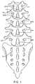
- Discogenic pain usually occurs at the lower lumbar discs of the spine ( Fig. 1 ). Pain is typically exacerbated when patients put their lumbar spines into flexion (i.e. by sitting or bending forward) and relieved when they put their lumbar spines into extension (i.e. the standing position, or arching backwards).
- Discogenic pain can be quite disabling, and for some patients, can dramatically affect their ability to work and otherwise enjoy their lives.
- Such discogenic low back pain can be thought of as flexion instability and is related to flexion instability that is manifested in other conditions.
- the most prevalent of these is spondylolisthesis, a spinal condition in which abnormal segmental translation is exacerbated by segmental flexion.
- Bone cerclage devices that can encircle the spinous processes or other vertebral elements and thereby create a restraint to motion.
- Physicians typically apply a tension or elongation to the devices that applies a constant and high force on the anatomy, thereby fixing the segment in one position and allowing effectively no motion.
- the lack of motion allowed after the application of such a device is thought useful to improve the likelihood of fusion performed concomitantly; if the fusion does not take, these devices will fail through breakage of the device or of the spinous process to which the device is attached.
- These devices are designed for static applications and are not designed to allow for a dynamic elastic resistance to flexion across a range of motion.
- the purpose of bone cerclage devices and the other techniques described above is to almost completely restrict measurable motion of the vertebral segment of interest. This loss of motion at a given segment gives rise to abnormal loading and motion at adjacent segments, leading eventually to adjacent segment morbidity.
- a spinal implant has been designed which inhibits spinal flexion while allowing substantially unrestricted spinal extension.
- the implant is placed over one or more adjacent pairs of spinous processes and provides an elastic restraint to the spreading apart of the spinous processes which occurs during flexion.
- Such devices and methods for their use are described in U.S. Patent Publication No. 2005/02161017A1, published on September 29, 2005 , and having common inventors with the present application.
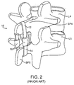
- an implant 10 as described in the '017 application typically comprises an upper strap component 12 and a lower strap component 14 joined by a pair of compliance members 16.
- the upper strap 12 is shown disposed over the top of the spinous process SP4 of L4 while the lower strap 14 is shown extending across the bottom of the spinous process SP5 of L5.
- the compliance member 16 will typically include an internal element, such as elastomeric members 72a and 72b ( Fig. 7 of the '017 application) which are attached to inelastic cables 76a and 76b in such a way that the cables may be "elastically" or “compliantly” pulled apart as the spinous processes SP4 and SP5 move apart during flexion.
- the compliance or elasticity is provided by the cables compressing the elastomeric members 72a and 72b between stoppers elements 78a, 78b, 80a, and 80b at their respective ends.
- the implant provides an elastic tension on the spinous processes which provides a force that resists flexion. The force increases as the processes move further apart and the rubber or elastomeric blocks become more compressed.
- the straps or cables themselves will be essentially non-compliant so that the degree of elasticity or compliance may be controlled and provided solely by the nature of the elastomeric members in compliance members 16.
- the "compressive" compliance members of the '017 application can have difficulty in providing controlled elastic tension within the relatively low 25 N/mm to 75 N/mm range set forth in the application.
- the use of compressive rubber or elastomeric blocks in the compliance members also limits the length of device elongation which can be achieved. Even if the initial compression provided by the block is within the target elastic resistance range, the stiffness of the compressive block would be expected to rise quickly and potentially fall outside of the target range as the block is further compressed by pulling of the spinous processes on the upper and lower straps.
- even such relatively “low” stiffnesses above 25N/mm can present some risk of damage or trauma to the spinous processes and other parts of the vertebrae and spine.
- the size of the compressive block may be increased.
- Increasing the size of the compressive block increases the overall size of the device and is undesirable.
- the need to have the straps or cables traverse the entire length of the compressive block also increases the size and complexity of the implant structure. Increasing the size of the device is undesirable for many reasons, including making implantation more difficult, while increasing the complexity of the device is undesirable as it increases the risk of failure.
- the improved devices could reliably and repeatedly provide relatively low initial tension on the spinous processes and a relatively low elastic resistance to flexion, even over relatively long lengths of travel. Moreover, any risk of damage to the vertebrae of spine should be minimized.
- the devices should have a relatively small size with a decreased complexity in order to facilitate implantation and reduce the risk of failure. Furthermore, the devices should be designed to continue to function even after being cycled for long periods of time (e.g. up to multiple years of implantation) through high numbers of cycles (e.g. up to millions of cycles) and as such should exhibit primarily elastic behavior with minimal plasticity, i.e., low creep. At least some of these objectives will be met by the inventions described hereinbelow.
- US Patent Publication No. 2005/0216017A1 has been described above.
- US 2005/0192581 describes an orthopedic tether which can have a stiffness from at least 1N/mm to at least 200N/mm and which can be used for many purposes, including wrapping spinous processes.
- Other patents and published applications of interest include: U.S. Patent Nos.
- WO 2005/112835 describes a prosthetic ligament having fasteners fixated in either the superior and inferior vertebrae or the superior and inferior prosthetic facet joint components.
- the fasteners may be selected from phone screws, hooks, wires, pins.
- the prosthetic facet joint ligament may have a tensibility of between 5 and 50N/mm.
- US 2005/216017 A1 discloses a spinal implant system for restricting flexion of a spine comprising an elongate band 22 with two ends and a connector 26 coupling the two ends of the elongated band to form the band into a loop to encircle two spinous processes, whereby the spring constant of the band being in the range from 25 N/mm to 75 N/mm.
- the present invention is set out in the appended claims. Described herein are spinal implants and methods for their use in restricting spinal flexion for the treatment of discogenic pain and other spinal conditions, such as spondylolisthesis, where the physician may desire to control spinal flexion.
- the implants and methods are particularly intended to dynamically limit flexion of at least one spinal segment by applying an elastic resistance between spinous processes on a pair of vertebrae, typically adjacent vertebrae, or between a spinous process, usually on L5, and a sacrum.
- the intent of the implants and methods is to limit motion between the vertebra while allowing at least several degrees of measurable motion. This will restrict flexion at the segment of interest without abnormally loading adjacent vertebral segments.
- the described methods and systems will provide a minimum and preferably no elastic resistance to extension of the spinal segments.
- the preferred methods and systems will usually be coupled to the spinous processes via flexible straps which, by virtue of their placement around the spinous processes and their flexible nature, make it very difficult for the preferred methods and systems of the present invention to provide any resistance to extension.
- the implants will usually be free from structure located between adjacent spinous processes, although in some cases structure may be provided where the structure does not substantially interfere with or impede the convergence of the spinous processes as the spine undergoes extension. While some small amount of elastic resistance to extension might be found, it will preferably be below 3 N/mm, more preferably below 1 N/mm, and usually below 0.5 N/mm.
- the preferred methods and systems will provide a minimum and preferably no elastic resistance to lateral bending or rotation of the spinal segments.
- the preferred methods and systems will usually be coupled to the spinous processes via flexible straps which, by virtue of their placement around the spinous processes and their flexible nature, make it very difficult for the preferred methods and systems of the present invention to provide any resistance to lateral bending or rotation. This is particularly true in the lumbar spine where the range of motion in rotation is usually limited to 3°. While some small amount of elastic resistance to lateral bending or rotation might be found, it will preferably be below 3 N/mm, more preferably below 1 N/mm, and usually below 0.5 N/mm.
- spinal segment refers to the smallest physiological motion unit of the spine which exhibits mechanical characteristics similar to those of the entire spine.
- the spinal segment also referred to as a “functional spinal unit” (FSU)
- FSU functional spinal unit
- the spinal segment or FSU see White and Panjabi, Clinical Biomechanics of the Spine, J.B. Lippincott, Philadelphia, 1990 .
- neutral position refers to the position in which the patient's spine rests in a relaxed standing position.
- the "neutral position” will vary from patient to patient. Usually, such a neutral position will be characterized by a slight curvature or lordosis of the spine where the spine has a slight anterior convexity and slight posterior concavity.
- the presence of the constraint of the present invention may modify the neutral position, e.g. the device may apply an initial force which defines a new neutral position having some small extension of the untreated spine.
- neutral position of the spinal segment refers to the position of a spinal segment when the spine is in the neutral position.
- “segmental flexion” refers to the motion between adjacent vertebrae in a spinal segment as the patient bends forward. Referring to Fig. 1A , as a patient bends forward from the neutral position of the spine, i.e. to the right relative to a curved axis A, the distance between individual vertebrae L on the anterior side decreases so that the anterior portion of the intervertebral disks D are compressed. In contrast, the individual spinous processes SP on the posterior side move apart in the direction indicated by arrow B. Segmental flexion thus refers to the relative movement between adjacent vertebrae as the patient bends forward from the neutral position illustrated in Fig. 1A .
- “segmental extension” refers to the motion of the individual vertebrae L as the patient bends backward and the spine extends from the neutral position illustrated in Fig. 1A . As the patient bends backward, the anterior ends of the individual vertebrae will move apart. The individual spinous processes SP on adjacent vertebrae will move closer together in a direction opposite to that indicated by arrow B.
- the phrase "elastic resistance” refers to an application of constraining force to resist motion between successive, usually adjacent, spinous processes such that increased motion of the spinous processes results in a greater constraining force.
- the elastic resistance will, in the inventions described herein, inhibit motion of individual spinal segments by, upon deformation, generating a constraining force transmitted directly to the spinous processes or to one or more spinous process and the sacrum.
- the elastic resistance can be described in units of stiffness, usually in units of force per deflection such as Newtons per millimeter (N/mm). In some cases, the elastic resistance will generally be constant (within ⁇ 5%) over the expected range of motion of the spinous processes or spinous process and sacrum.
- the elastic resistance may be non-linear, potentially varying from 33 % to 100 % of the initial resistance over the physiologic range of motion.
- the preoperative range of motion of the spinous process spreading from the neutral or upright position to a maximum flexion-bending position will be in the range from 2 mm to 20 mm, typically from 4 mm to 12 mm.
- the post-operative range of motion of the spinous process spreading from the neutral or upright position to a maximum flexion-bending position will be reduced and will usually be in the range from 1 mm to 10 mm, typically from 2 mm to 5 mm.
- Such spinous process spreading causes the device to undergo deformations of similar magnitude.
- a method for restricting flexion of at least one spinal segment comprises implanting a constraining structure having a superior end coupled to a superior spinous process and an inferior end coupled to an inferior spinous process or a part of the sacrum.
- the constraining structure provides an elastic resistance to flexion beyond a neutral position of the spinal segment in the ranges set forth above.
- the constraining structure provides substantially no resistance to extension of the spinal segment beyond the neutral position, typically being below the forces set forth above.
- the constraining structure may be implanted by placing a superior tether structure over or through the superior spinous process and placing an inferior tether structure over or through the inferior spinous process or part of the sacrum.
- the tether structures are preferably non-distensible and joined by at least one compliance member which provides the desired elastic resistance to flexion.
- the superior and inferior tether structures will be joined by a pair of compliance members which are symmetrically placed on the right and left sides of a midline of the spinal segment, where each compliance member provides about one half of the total elastic resistance to be applied to the spinal segment. That is, the individual compliance members will preferably provide an elastic resistance below 12.5 N/mm, usually below 10 N/mm, typically in the range from 3.75 N/mm to 8.75 N/mm, and preferably in the range from 5 N/mm to 7.5 N/mm.
- the elastic resistance to flexion applied by the constraining structure is exerted when the spinal segment moves beyond the neutral position and will depend on several factors including the elastic characteristics of the constraining structure, the position of the constraining structure on the spinous processes, the dimensions of the constraining structure, and the patient's anatomy and movement.
- the constraining structure will usually be positioned so that the upper and lower tethers engage the middle anterior region of the spinous process, and the dimensions of the constraining structure will usually be adjusted so that the tethers are taut, i.e. free from slack, but essentially free from tension (axial load) when the spinal segment is in its neutral position, i.e., free from flexion and extension. As the segment flexes beyond the neutral position, the constraining structure will immediately provide an elastic resistance in the ranges set forth above.
- the dimensions and assembly of the construct will be selected so that the tethers and compliance members are slightly pre-tensioned even before the compliance members are under load.
- the constraining structure will apply a predetermined resistive force, typically in the range from 5N to 25N, as soon as the spinal segment flexes from the neutral position.
- the compliance members would apply a zero resistive force at the instant they are placed under load.
- the constraining structure will provide increasing elastic resistance in the ranges set forth above.
- the constraining structures will apply minimal or no force when the spinal segment is in the neutral position. In some instances, however, it may be desirable to tighten the constraining structure over the spinous processes so that a relatively low finite force (typically in the range from 1N to 25N, usually from 5N to 15N) is applied even before flexion while the spinal segment remains at a neutral position.
- a relatively low finite force typically in the range from 1N to 25N, usually from 5N to 15N
- the relatively low elastic resistance afforded by the constraining structures of the present invention is advantageous because the resulting low forces allow the constraining structure to resist flexion sufficiently to improve the underlying pain or instability with a reduced risk of injury from excessive force.
- the preferred elastic resistance ranges set forth above provide sufficient constraint to effect a significant change in flexion in the typical patient while allowing a significant safety margin to avoid the risk of injury.
- the elastic resistance provided by the constraints of the present invention will limit the separation of the spinous processes on the treated spinal segment which is desirable both to reduce flexion-related pain and spinal instability.
- the resistance to flexion provided by the elastic constraints of the present invention will reduce the angular range-of-motion (ROM) relative to the angular ROM in the absence of constraint.
- Angular ROM is the change in angle between the inferior end plate of the superior vertebral body of the treated segment and the superior endplate of the inferior vertebral body of the treated segment when the segment undergoes flexion.
- the treatments afforded by the elastic constraints of the present invention will provide a relatively low angular ROM for the treated segment, but typically a ROM higher than that of a fused segment.
- the described methods and devices will allow a controlled degree of flexion to take place.
- the methods and devices will allow a degree of flexion which is equal to at least about 25% of the flexion that would be observed in the absence of constraint, more typically being at least about 50%.
- the constraint structures will act to restore the stiffness of a spinal segment which is "lax" relative to adjacent segments.
- a patient with flexion-related pain or instability suffers from a particular looseness or laxity at the painful segment.
- the painful, lax segment will preferentially flex relative to the stiffer adjacent segments.
- the stiffness of the treated segment can be "normalized” immediately as the patient begins to impart flexion to the spine.
- premature and/or excessive flexion of the target spinal segment can be inhibited or eliminated.
- Compliance members with different stiffnesses, elongations (lengths of travel), and other characteristics can be selected for particular patients based on their condition. For example, patients suffering from a severe loss of stiffness in the target spinal segment(s) may be treated with devices that provide more elastic resistance. Conversely, patients with only a minimal loss of natural segmental stiffness can be treated with devices that provide less elastic resistance. Similarly, bigger patients may benefit from compliance members having a greater maximum elongation, while smaller patients may benefit from compliance members having a shorter maximum elongation.
- the present invention can provide for "pre-tensioning" of the constraining structure. As described above, one way to accomplish this is by shortening the constraining structure such that a small amount of tension is held by the constraining structure when the spine is in the neutral or slightly extended initial position. Alternatively, pre-tensioned compliance elements can be provided to pre-tension the constraining structure without changing its length.
- the tension or compression elements utilized in the compliance members of the present invention such as coil springs, elastomeric bodies, and the like, will typically present little or no elastic resistance when they are first deformed. Thus, there will be some degree of elongation of the compliance members prior to the spinal segment receiving a therapeutic resistance.
- the tension or compression members may be pre-tensioned to have an initial static resistive force which must be overcome to initiate deformation.
- a constrained spinal segment will not begin to flex at the instant the patient begins to flex her or his spine which is an advantage when treating lax spinal segments.
- the constraint has at least one dimension that is adjustable to allow tightening over the spinous processes or spinous process and sacrum intra-operatively.
- the constraint will also provide a resistance to flexion of the spinal segment beyond the neutral position in the ranges set forth above.
- the constraint provides little or no elastic resistance to extension beyond the neutral position within the limits set forth above.
- the constraint comprises a superior tether structure adapted to couple to the superior spinous process and an inferior tether structure adapted to couple to the inferior spinous process or sacrum.
- the tether structures may be a single, continuous segment, such as a band, cable, cord, strap, braid, webbing, or the like.
- the tether structure may comprise two or more individual components attached in a series, in parallel, or in any other configurations.
- the tether structures will be non-compliant so that they are essentially non-extensible when subjected to an axial force, typically elongating less than 5%, usually elongating less than 2% when subjected to a force of 100 N; in the context of the application of such tether structures across a pair of spinous processes or a spinous process and sacrum, such elongations will typically by less than 2mm, usually less than 1mm.
- the devices will comprise at least two compliance members arranged to lie symmetrically on either side of a midline of the spinal segment when the tether structures are placed over the spinous processes or spinous process and sacrum.
- the constraining structures will be implanted for a number of years, often over millions of use cycles, it is desirable that the elastic constraints remain dimensionally constant and have constant elastic characteristics.
- the dimensional stability of the devices will be improved, particularly relative to other constraining structures which employ elongate polymeric cables for constraining adjacent spinous processes.
- the tethers joining the compliance members will be non-distensible and have a very high tensile strength, preferably greater than 500N, more preferably greater than 2000N.
- Such a high tensile strength will minimize "creep" (elongation over time) in the tether structures, preferably so that the long-term creep of the tethers under physiologic loads will be less than 10%, usually less than 5% and preferably less than 1%, over millions of use cycles and many years so that overall elongation of the constraint contributed by the tethers over the implanted life of the constraint will be less than 2mm, usually less than 1 mm, and preferably less than 0.5 mm.
- the use of woven tethers, such as woven polymeric tethers is strictly advantageous for their flexibility in non-loaded directions, and since the fibers are oriented in a direction which is aligned with that of the load.
- the dimensional stability can be improved by appropriate selection of materials and design.
- a system for restricting flexion of at least one spinal segment comprises a superior tether structure, an inferior tether structure, a right compliance member, and a left compliance member.
- the superior tether structure is adapted to couple to a superior spinous process and includes a right connecting segment and a left connecting segment.
- the tether structure will be very flexible but essentially non-extensible so that it will stretch very little when subjected to the axial loads experienced after it is implanted. The particular limits on extensibility are described above.
- the inferior tether structure will have similar properties and is adapted to couple to the inferior spinous process or to a sacrum.
- the right compliance member includes a tension element having an upper end connectable to the right connecting segment of the superior tether structure and a lower end connectable to the right connecting segment of the inferior tether structure.
- the left compliance member includes a tension element having an upper end connectable to the left connecting segment of the superior tether structure and a lower end connectable to the left connecting element of the inferior tether structure.
- each of the tether structures is usually pre-attached to one end of the tension element of each of the two compliance members.
- the pre-attached end will be fixedly attached.
- the other, free end of each tether structure will usually be received in an adjustable connecting element or component which is part of the other compliance member, as described in more detail below.
- the adjustable connecting element will preferably be reversibly adjustable, allowing positioning and repositioning of the tether relative to the compliance member without damaging either component.
- a particularly preferred example of such an adjustment member is a roller which is described in detail hereinafter.
- the compliance members may comprise a sheath which covers the tension element.
- the sheath may incorporate battens which prevent the sheath from interacting with the coils (e.g. by pinching or wearing).
- the compliance members may each comprise an element that limits elongation, such as a cord or the like. Usually, such elongation limit prevents elongation of the tension element to 20 mm, preferably to 10 mm beyond its neutral unstressed condition.
- the tension elements each comprise a coil spring having a superior tether connector and an inferior tether connector.
- One of the tether connectors on each tension element will be adapted for fixed attachment while the other will be adapted for adjustable attachment.
- the coil spring and tether connectors are formed from a single piece of material, such as a metal blank or rod. Alternatively, they may be formed from a single polymeric blank.
- the adjustable connector may comprise a rotatable roller for adjustably receiving a connecting segment of the free tether structure from the other compliance member.
- the tension elements comprise an elastomeric body having a superior tether connector and an inferior tether connector.
- the elastomeric body typically comprises a beam having discrete superior and inferior passages to define the tether connectors.
- the elastomeric body may comprise a ring having a central opening which defines both the tether connectors.
- the elastomeric body comprises an elastomer having a relatively low durometer, such as silicone rubber as well as various thermoplastics and thermosetting elastomers.
- the elastomeric body may be pre-cycled and tensioned to stabilize the stiffness value. The stiffness value will typically be in the ranges set forth above.
- the systems 10 comprise a superior tether structure 12, and inferior tether structure 14, and right compliance member 16 and a left compliance member 18.
- the superior tether structure 12 will typically be a continuous band, cable, strap, cord, or other structure which extends between the two compliance members and provides a saddle region 20 which is adapted to lie over and conform to a superior surface of a superior spinous process SSP as described in more detail in the related prior applications which have been incorporated herein by reference.
- the inferior tether structure 14 will typically comprise a band, cable, or the like which is constructed similarly if not identically to the superior tether structure 12 and has a saddle region 22 adapted to lie over and conform to an inferior surface of an inferior spinous process 22.
- the inferior tether structure 14 may comprise separate bands, cables, straps, cords, or the like, 14a and 14b, shown in broken line, which have anchors 15a and 15b at their lower ends and are adapted to be separately attached to an inferior vertebrae or more commonly to a sacrum.
- the use of such separate tether structures for inferior attachment are described in more detail in co-pending application 11/827,980 (Attorney Docket No. 026398-000120US).
- the tether structures will usually be flexible but effectively non-compliant so that they allow minimum elongation under tensile load.
- the right and left compliance members 16 and 18 will usually have similar or identical constructions and include an adjustable attachment component 32 and a fixed attachment component 34 for securing connecting segments of the superior and inferior tether structures 12 and 14.
- each compliance member 16 and 18 will have one of the tether structures 12 and 14 pre-attached to the fixed attachment component 34.
- the two subassemblies can then be introduced onto opposite sides of the spinous processes, and the tether structures placed over the spinous processes or otherwise attached to the vertebral bodies, as generally described in co-pending application 11/875,674 (Attorney Docket No. 026398-000150US).
- the tension elements 30 will elastically elongate as tension is applied by the superior and inferior tether structures 12 and 14 through the attachments 32 and 34, in the direction shown by arrow 36.
- the superior and inferior tether structures 12 and 14 will also move apart, as shown generally in broken line in Fig. 3 .
- a tension element 30 will elastically resist the spreading with a force determined by the mechanical properties of the tension member.
- the tension members will be selected to have a tensile or elastic stiffness, also known as a spring constant, in the relatively low ranges set forth above.
- a tensile or elastic stiffness also known as a spring constant
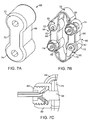
- a first exemplary tension element 40 constructed in accordance with the principles of the present invention is illustrated in Figs. 4, 5A and 5B .
- the tension element 40 comprises a helical spring structure 41 formed from a single piece of material.
- the tension member 40 includes an adjustable tether connector 42 and a fixed tether connector 44, both of which are preferably formed integrally or monolithically with the helical spring structure 41.
- the helical spring structure 41 and both tether connectors 42 and 44 will be formed from one piece of material, usually being a metal such as titanium, but optionally being a polymer, ceramic, reinforced glass or other composite, or other material having desired elastic and mechanical properties and capable of being formed into the desired geometry.
- the tension member 40 is machined or laser cut from a titanium rod.
- a suitable polymeric material will be polyethylene ether ketone (PEEK).
- PEEK polyethylene ether ketone
- Other features may be built into the tension member 40, such as a stress relief hole 46.
- Components that mate with the adjustable tether connector may potentially include a roller and a lock-nut; such components could be made from the same material as the tension element and adjustable tether connector (e.g. titanium components if the tension member is titanium), or they could be made from a different material (e.g. injection molded PEEK).
- the exterior of the tension member 40 may be covered with a protective cover, such as the elastomeric sheath 50 illustrated in Fig. 5A .
- the sheath 50 may be placed over the body of the tension member 40, as illustrated in Fig. 5B , in order to prevent the intrusion of tissue and body materials into the spaces between the turns of the coil and interior of the element.
- a free end 53 of the tether structure 52 may be attached to the adjustable tether connector 42, as illustrated in Fig. 6A through 6C .
- a barrel locking mechanism 54 is rotationally aligned such that a slot 56 is aligned with an inlet opening 58 on the top of the connector 42 and an outlet opening 60 on the side of the connector.
- the inlet opening 58 is located centrally and providing a primarily axial load on the compliance member, thereby evenly loading the compliance member and having the advantages described above.
- the free end 55 of tether 52 is then advanced through the inlet opening 58, slot 56, and outlet opening 60, as illustrated in Fig. 6C .
- this simple locking mechanism allows tether 52 to be appropriately tensioned for the individual patient before locking the tether in place.
- a locking feature e.g. set screw, nut, or pin (not shown) would then be used to lock the tether and roller in place, providing additional resistance to unfurling and opening. The tensioning could be performed separately and/or simultaneously during implantation of the constraint assembly. Additional features of the mechanism such as pins, shoulders, or other features which control the travel of the roller or lock-nut may aid in the alignment and operation of the mechanism.
- Another tether structure (not illustrated) will be attached to the fixed connector 44 at the other end of the tension element 40, typically using a pin (not illustrated).
- the pin may be anchored in a pair of receiving holes 62, and a free end of the tether wrapped over the pin and firmly attached.
- the fixed tether structure will be pre-attached at the time of manufacture so that the treating physician can implant each of the pair of tension members, with one tether structure attached to the fixed tether connector.
- the remaining free ends of each tether structure 52 may then be deployed around the spinous processes (or attached to a sacrum) in a pattern generally as shown in Fig. 3 .
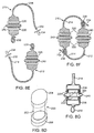
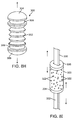
- FIG. 7A-7C An alternative tension element 66 comprising an elastomeric body 68 is illustrated in Figs. 7A-7C .
- the elastomeric body 68 comprises a central tensile segment 70 joined by a pair of ring connectors 72 and 74.
- the entire structure will be molded or cast from an elastomeric material having mechanical properties that provide the desired elastic stiffness or spring force, as set forth above.
- a particularly suitable elastomer is silicone rubber, but other thermoplastics and thermosetting elastomers could also be used.
- the tension elements 66 may be joined to tether structures 76 and 78, as shown in Fig. 7B .
- each tether structure 76 and 78 is fixably attached to one tension element 66 at one end and adjustably attached to the other tension element at the other end.
- one end of the superior tether structure 76 is fixedly attached to the upper end of the left tension member 66 by wrapping around a shackle 80 which is attached to the ring connector 72 with a pin or bolt 82.
- one end of the inferior tether structure 78 is fixedly attached to ring connector 72 on the lower end of the right tension element 66 using a shackle 82.
- adjustable attachment of the tether structures 76 and 78 is provided by a cord 84 which may be loosened or tightened in a locking structure comprising mating surfaces on a nut 86 and pin 88 assembly, as shown in Fig. 7C .
- the pin 88 is received in the ring connector 74 and holds a threaded cup 90 in place.
- the nut 86 is threadably received in the cup 90 and can be axially translated relative to the mating surface of pin 88.
- the cord 84 may be passed freely through the assembly when the nut 86 is loosened. Once the desired tension is placed on the tether structure 76 or 78, the nut 86 can be tightened to hold the cord 84 in place.
- FIGs. 8A-8C A further alternative embodiment of a tension element 100 is illustrated in Figs. 8A-8C .
- the tension element 100 comprises a single elastomeric ring structure 102 having a large central opening 104.
- the elastomeric ring can be formed from any of the elastomers listed above for element 66.
- a pair of the tension elements 100 may be held in place by tether structures 106, as illustrated in Fig. 8B . Ends of the tether structures 106 may be looped through the central opening 104 to provide a continuous circumferential structure. As illustrated in Fig. 8B , there is no adjustability of the circumferential length of the structure.
- tether ends may be left free so that the loop may be tightened and then held in place, for example using crimping structure 110, as illustrated in Fig. 8C .
- crimping structure 110 as illustrated in Fig. 8C .
- four tether structures could be used, each pre-attached in the form of a permanent, closed loop around each end of each ring.
- Two inferior structures could then be attached (e.g. by crimping) to each other, and two superior structures could similarly be attached to each other.
- an alternative elastomeric tension element 200 comprises an elongate elastomeric body 202 having an upper cap member 204 and a lower cap member 206.
- the body 202 is formed from any of the elastomeric materials listed above and will provide an elastic resistance to elongation when opposite tensile forces are placed on the caps 204 and 206.
- the elastomeric tension elements 200 may be incorporated into a superior tether structure 210 and an inferior tether structure 212, as seen in Figs. 8E and 8F .
- Each of the tether structures 210 and 212 comprises a sheath 214 which is formed from a braided polymer or other substiantially non-distensible fabric, textile or other material, typically being formed from polyester or polyethylene.
- the sheath has a generally tubular structure, and the braided or other fabric structure allows it to be radially expanded to accommodate an elastic tension element 200 at one end. As best seen in Fig.
- the elastic tension element 200 is placed in an end of the sheath 214 and secured by rings or bands 220 which are placed over the exterior of the sheath and which are held in place by collars 222.
- the collars 222 are typically formed from biologically inert polymer or metal, such as PEEK or titanium, and serve to transfer load from the sheath 214 to the cap members 204 and 206 and thus the elastomeric body 202 as a tensile load is placed on the sheath 214.
- a particularly convenient approach is to form a connecting loop 230 at the end of the sheath 214 which holds the elastic tensioning element 200.
- the loop 230 may be formed simply by stretching and folding the end of the sheath and attaching the end to the body of the sheath, by heat sealing, adhesives, crimps, or the like.
- the two tether structures 210 and 212 may be joined into a continuous loop for placement over the spinous processes by drawing distal ends 232 of each sheath 214 through the loop 230 of the opposite tether structure, as best seen in Fig. 8F .
- the distal end may be fixed in place, typically using an anchor 234 which can be crimped in place.
- a slack region 240 will be provided in the sheath 214 between the retention rings 220 to allow desired elongation of the elastomeric body 202.
- Figs. 8H and 8I illustrate particular embodiments for elastomeric tension and compression elements suitable for use in the spinous process constraint systems.
- the elastomeric tension element 300 is formed similarly to tension element 200 and includes an elastomeric body 302 having an upper cap member 304 and a lower cap member 306.
- the tension member 300 will typically also include collars 308 which are used to couple the tension member to tether structures.
- the body is formed with a corrugated or "accordion" profile. The accordion profile allows the degree of elasticity to be increased relative to a similar sized elastomeric body having a cylindrical profile.
- the elastomeric compression member 320 is illustrated in Fig. 8I .
- the elastomeric compression member 320 may be formed from any of the elastomeric materials described above, but will be formed to have a number of holes or voids 322.
- the formation of elastomers having such holes or voids may be accomplished by molding or extruding the elastomer with materials that are later removed to leave the voids in place.
- the presence of such voids in the elastomeric body 320 serves to enhance or help control the compressive elasticity of the member.
- the superior and inferior tether members 330 and 332 will pass through the body and be anchored on opposite ends to end caps 334 and 336, respectively, so that axial tension on the tether structures, as indicated by the outward arrows, will compress the elastomeric body 320, as indicated by the inwardly facing arrows.
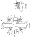
- FIG. 9A-9B Another flexion restriction system 120, as illustrated in Figs. 9A-9B , comprises a pair of leaf spring structures 122, each of which includes an S-shaped center portion 122 and two tether connectors 126. Superior and inferior tether structures 130 and 132 respectively, each have two free ends which are adjustably received in the tether connectors 126. Each of the tether connectors 126 includes a screw with clamping surfaces 132 which may be loosened or tightened in order to permit adjustment of the tension on the tether structure as desired, as shown in Fig. 9B .
- the S-shaped center portion 124 of the leaf spring structure 122 may be formed from a metal, polymer, reinforced composite, or any other material which can be fabricated to provide an elastic stiffness or spring constant within the ranges described above.
- the tether connectors 126 may be formed integrally or monolithically with the center portions 124, or alternatively may be formed separately and adhered using adhesives, fasteners, or the like.
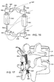
- the system 140 comprises a pair of compliance members 142 attached to superior and inferior tether structures 144 and 146, respectively.
- the compliance members 142 each comprise a fixed tether connector 148 and an adjustable tether connector 150.
- the tether connectors 148 and 150 are joined by a coil spring 152 (best seen in Fig. 10B ) which is enclosed within a textile sheath 154.
- the superior tether structure 144 is fixably connected to the fixed tether connector 148 on the left hand side compliance member 142, while the inferior tether structure 146 is fixedly connected to the fixed connector 148 on the right compliance member 142.
- Each of the adjustable tether connectors 150 includes a latch arm cam lock 156 which may be lifted or opened, as shown in Fig. 10A , to allow a free end of the tether structure 144 or 146 to be advanced therebeneath so that the tether can be tightened or cinched over an adjacent spinous process. Once the tether structure 144 or 146 has been sufficiently tightened, the latch arm 156 may be closed, as shown in Fig. 10B , to hold the tether structure 144 or 146 firmly in place. To prevent loosening, each latch arm cam lock 146 may be provided with surface textures or other gripping features such as spikes or chevrons 158.
- the coil spring 152 may be secured to the fixed and adjustable tether connectors 148 and 150 by any conventional technique. In certain cases, however, it may be desirable to provide a pivotable or adjustable connection, as shown in Fig. 11 .
- ball joints 160 may be formed on superior and inferior connectors 162 and 164, respectively.
- a coil spring 166 may have converging ends 168 which can be secured over the ball joints to provide a universal joint therebetween.
- Coil spring tension members may be secured to both fixed and adjustable tether connectors, such as connectors 148 and 150 in Figs. 10A and 10B , in a variety of ways.
- a tether connector 250 may be attached to an end of a coil spring 252 using a threaded receiving component 254 which can be screwed in to the coil spring, as illustrated in Fig. 10D .
- the threaded receiving component 254 mates with the coil spring, typically by threadably engaging the internal grooves on the coil spring, thus evenly spreading the tension across the end of the spring.
- the receiving component 254 can be welded in place, held in place by a suitable adhesive, or be held in place by various secondary fasteners, such as screws, rivits, or the like.
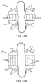
- the flexible restraint system 170 may be identical in all respects to the flexible restraint system 140 as described previously. Instead of a mesh sheath, however, the flexible restraint system 170 includes a sheath having a plurality of battens or wires 172 which reduce interactions between the sheath and restraint system, as well as provide an axial constraint to limit the maximum axial separation of the fixed and adjustable tether connectors 174 and 176, respectively. As shown in Fig. 12A , the battens 172 are axially compressed so that they bow outwardly, distancing the sheath from the tensile member. In Fig. 12B , the fixed and adjustable tether connectors 174 and 176 have moved to their maximum axial separation, straightening the battens 172.
- the flexible restraint system 180 is similar to those of both systems 170 and 140, except that the sheath structure has an accordion fold to provide for lengthening and shortening together with the movement of fixed and adjustable tether connectors 182 and 184, respectively.
- the accordion folds both permit greater gross elongation of the sheath with lower material strains than in a purely cylindrical sheath and potentially reduce interaction between the sheath and tensile member.
- the sheath with the accordion fold may or may not act as a constraint on maximum elongation of the compliance members.
- the sheath could also be used with separate tension members for providing the maximum elongation limit.
- a compliance member 260 includes a spring compression member 262 placed in a housing 264 and a superior tether structure 266 which is secured to a piston 268 which is free to slide within an interior chamber 270 of the housing 264.
- the coil spring 262 is disposed between an upper surface of the piston 268 and the lower surface of the top end of the housing 260. If the coil spring 262 is sized so that it occupies the space between the piston and the top end of the housing without any compression, then the compliance member 260 will have no pre-tensioning or pre-loading.
- the spring 262 will be chosen to be slightly longer than the distance between the piston and the top end of the housing so that the spring 262 is under compression even when there is no tension being placed on the superior tether 266 or the inferior tether 267.
- the degree of pre-tensioning can be controlled by selecting the position of retaining shoulders 270 formed on the interior surface of the housing 264.
- the compliance member 260 will apply elastic resistance to spreading of tension members 266 and 267 as the spring compresses in the direction of the arrows.
- Compliance member 280 includes a tension spring member 282 received in the interior 284 of housing 286.
- a superior tether structure 288 is attached to an upper end of the housing 286 and an inferior tether structure 290 is attached to a piston 292 slidably received in the interior 284 of the housing.
- Movement of the piston 292 is constrained by a shoulder 294 formed about the circumference of the interior 284. If the spring 282 is selected so that its length is equal to the length between the piston (when engaged against the shoulder 294) and the upper end of the interior 284, then there will be no pre-tensioning of the spring. If, however, the spring is selected so that it is shorter than the distance between the piston 292 and the upper end of the chamber 284, then the spring will be in tension at all times, even prior to elongation by placing a force between the tether structures. In this way, the initial displacement of the tether structures relative to each other will act to overcome the pre-tensioning force of the spring.
- Fig. 15A the relationship between force F and displacement D for a compliance member without pre-tensioning is illustrated.
- the spring force Prior to displacement, when the displacement is zero, the spring force will be essentially zero. The spring force will increase linearly from zero depending on the spring constant k as illustrated.
- the tension member 262 or 284 is pre-tensioned, however, the initial force imparted by the compliance member will be F 0 (greater than zero), as shown in Fig. 15B .
- the magnitude of Fo is determined by the degree of pre-tensioning, typically being in the range from 0N to 50N, usually from 5N to 25N, for the compliance members herein. Once displacement begins, however, the increase in force (F-F 0 ) will be linear and again determined by the spring constant k.
- spinous constraint structures have generally included flexible, typically non-distensible, tethers or bands adjoining the superior and inferior ends of the compliance members.
- the compliance members could be joined by a rigid frame structure 340, as illustrated in Fig. 16 .
- compliance members 342 could be joined to superior and inferior yokes 344 and 346, each of which include a central engagement member 348 for placement over the superior and inferior spinous processes.
- the engagement members 348 could be pivotally attached between a pair of adjacent wing members 350.
- the wings members 350 could be coupled to the compliance members 342 using rods or posts 352, where the rods or posts 352 are optionally threaded to allow adjustment and tightening of the yokes 344 and 346 over the spinous processes.
- the compliance members 342 could have any of the tension members and coupling structures described previously in order to connect to the posts 352.
- compliance members 360 could be joined by superior and inferior tether structures 362 and 364 each of which comprises a plurality of individual coupling elements 366.
- the individual coupling elements 366 could include filaments, strands, fibers, wires, small diameter cables, and the like, composed of polymers, metals, metal-polymer composites, and the like.
- Coupling elements could be simple constant diameter elongate elements, but could alternatively comprise regions of different characteristics, including elastic regions, spring-like regions, rigid regions, or the like.
- the individual fibers will typically be free to move relative to each other so that they independently function to couple the compliance members 360 together.
- the individual coupling elements 366 could be woven or braided together along a portion of or their entire lengths.
- An advantage of the use of individual coupling elements is that the elements may spread and conform to the particular geometry of the spinous process providing a more stable connection.
- Certain embodiments, in the coupling elements could be composed entirely or in part of a material that promotes tissue ingrowth, such as tantalum.
- an upper tether member 380 can be provided with a scale or other indicia 382 that indicates the displacement or band length.
- the scale or indicia 382 could be calibrated to show displacement force.
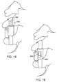
- the displacement or force measurement could also be provided in an indicator window 390 in a compliance member 392, as shown in Fig. 19 .
- the indicia will be visible by the physician during the implantation procedure.
- the indicia could be transmitted for reading during implantation procedure and optionally after implantation.
- the indicia could be configured so that it is visible on imaging procedures, such as x-rays, MRI'S and the like.
Landscapes
- Health & Medical Sciences (AREA)
- Orthopedic Medicine & Surgery (AREA)
- Life Sciences & Earth Sciences (AREA)
- Neurology (AREA)
- Surgery (AREA)
- Heart & Thoracic Surgery (AREA)
- Engineering & Computer Science (AREA)
- Biomedical Technology (AREA)
- Nuclear Medicine, Radiotherapy & Molecular Imaging (AREA)
- Medical Informatics (AREA)
- Molecular Biology (AREA)
- Animal Behavior & Ethology (AREA)
- General Health & Medical Sciences (AREA)
- Public Health (AREA)
- Veterinary Medicine (AREA)
- Surgical Instruments (AREA)
- Prostheses (AREA)
Applications Claiming Priority (2)
| Application Number | Priority Date | Filing Date | Title |
|---|---|---|---|
| US93689707P | 2007-06-22 | 2007-06-22 | |
| PCT/US2008/060908 WO2009002594A1 (en) | 2007-06-22 | 2008-04-18 | Methods and devices for controlled flexion restriction of spinal segments |
Publications (3)
| Publication Number | Publication Date |
|---|---|
| EP2182864A1 EP2182864A1 (en) | 2010-05-12 |
| EP2182864A4 EP2182864A4 (en) | 2013-01-02 |
| EP2182864B1 true EP2182864B1 (en) | 2016-06-08 |
Family
ID=40137307
Family Applications (1)
| Application Number | Title | Priority Date | Filing Date |
|---|---|---|---|
| EP08746344.4A Active EP2182864B1 (en) | 2007-06-22 | 2008-04-18 | Devices for controlled flexion restriction of spinal segments |
Country Status (5)
| Country | Link |
|---|---|
| US (1) | US8403961B2 (enExample) |
| EP (1) | EP2182864B1 (enExample) |
| JP (2) | JP2010530780A (enExample) |
| CN (1) | CN101715323A (enExample) |
| WO (1) | WO2009002594A1 (enExample) |
Families Citing this family (154)
| Publication number | Priority date | Publication date | Assignee | Title |
|---|---|---|---|---|
| US8523904B2 (en) | 2004-03-09 | 2013-09-03 | The Board Of Trustees Of The Leland Stanford Junior University | Methods and systems for constraint of spinous processes with attachment |
| US8034085B2 (en) | 2004-05-28 | 2011-10-11 | Depuy Spine, Inc. | Non-fusion spinal correction systems and methods |
| EP1814474B1 (en) | 2004-11-24 | 2011-09-14 | Samy Abdou | Devices for inter-vertebral orthopedic device placement |
| US7901437B2 (en) | 2007-01-26 | 2011-03-08 | Jackson Roger P | Dynamic stabilization member with molded connection |
| US8123749B2 (en) * | 2005-03-24 | 2012-02-28 | Depuy Spine, Inc. | Low profile spinal tethering systems |
| US8162982B2 (en) | 2006-10-19 | 2012-04-24 | Simpirica Spine, Inc. | Methods and systems for constraint of multiple spine segments |
| US8029541B2 (en) | 2006-10-19 | 2011-10-04 | Simpirica Spine, Inc. | Methods and systems for laterally stabilized constraint of spinous processes |
| US8187307B2 (en) * | 2006-10-19 | 2012-05-29 | Simpirica Spine, Inc. | Structures and methods for constraining spinal processes with single connector |
| US20100036424A1 (en) * | 2007-06-22 | 2010-02-11 | Simpirica Spine, Inc. | Methods and systems for increasing the bending stiffness and constraining the spreading of a spinal segment |
| CN101854872B (zh) * | 2007-09-14 | 2014-04-30 | 新特斯有限责任公司 | 椎间间隔器 |
| US8303591B1 (en) * | 2008-03-18 | 2012-11-06 | Dallen Medical, Inc. | Load shaping for dynamic tensioning mechanisms and methods |
| US8308771B2 (en) | 2008-06-06 | 2012-11-13 | Simpirica Spine, Inc. | Methods and apparatus for locking a band |
| WO2009149399A1 (en) | 2008-06-06 | 2009-12-10 | Simpirica Spine, Inc. | Methods and apparatus for deploying spinous process constraints |
| WO2010028165A1 (en) | 2008-09-03 | 2010-03-11 | Simpirica Spine, Inc.6 | Methods and apparatus for coupling a prosthesis to a spinal segment |
| US9044278B2 (en) * | 2008-11-06 | 2015-06-02 | Spinal Kinetics Inc. | Inter spinous process spacer with compressible core providing dynamic stabilization |
| EP2346425A4 (en) | 2008-11-12 | 2012-04-18 | Simpirica Spine Inc | MODULATED STRAIN APPARATUS AND METHODS OF USE |
| IT1392200B1 (it) * | 2008-12-17 | 2012-02-22 | N B R New Biotechnology Res | Stabilizzatore vertebrale modulare. |
| US8540452B2 (en) * | 2008-12-31 | 2013-09-24 | Spinex Tec, Llc | Flexible joint arrangement incorporating flexure members |
| EP2395931A4 (en) * | 2009-02-02 | 2013-10-30 | Simpirica Spine Inc | CROSSBOW BELT ANCHORING AND USE METHOD THEREFOR |
| JP5681122B2 (ja) | 2009-03-10 | 2015-03-04 | シンピライカ スパイン, インコーポレイテッド | 外科用テザー装置および使用方法 |
| WO2010104935A1 (en) | 2009-03-10 | 2010-09-16 | Simpirica Spine, Inc. | Surgical tether apparatus and methods of use |
| US8562653B2 (en) | 2009-03-10 | 2013-10-22 | Simpirica Spine, Inc. | Surgical tether apparatus and methods of use |
| US8628577B1 (en) | 2009-03-19 | 2014-01-14 | Ex Technology, Llc | Stable device for intervertebral distraction and fusion |
| US8668719B2 (en) | 2009-03-30 | 2014-03-11 | Simpirica Spine, Inc. | Methods and apparatus for improving shear loading capacity of a spinal segment |
| US9668771B2 (en) | 2009-06-15 | 2017-06-06 | Roger P Jackson | Soft stabilization assemblies with off-set connector |
| CA2768867C (en) | 2009-07-22 | 2018-04-24 | Spinex Tec, Llc. | Methods and apparatuses for vertebral body distraction and fusion employing a coaxial screw gear sleeve mechanism |
| US10098758B2 (en) | 2009-10-15 | 2018-10-16 | Globus Medical, Inc. | Expandable fusion device and method of installation thereof |
| US9155628B2 (en) | 2009-10-15 | 2015-10-13 | Globus Medical, Inc. | Expandable fusion device and method of installation thereof |
| US11344430B2 (en) | 2009-10-15 | 2022-05-31 | Globus Medical, Inc. | Expandable fusion device and method of installation thereof |
| US8556979B2 (en) * | 2009-10-15 | 2013-10-15 | Globus Medical, Inc. | Expandable fusion device and method of installation thereof |
| US10806596B2 (en) | 2009-10-15 | 2020-10-20 | Globus Medical, Inc. | Expandable fusion device and method installation thereof |
| US8679183B2 (en) * | 2010-06-25 | 2014-03-25 | Globus Medical | Expandable fusion device and method of installation thereof |
| US8062375B2 (en) | 2009-10-15 | 2011-11-22 | Globus Medical, Inc. | Expandable fusion device and method of installation thereof |
| US11564807B2 (en) | 2009-10-15 | 2023-01-31 | Globus Medical, Inc. | Expandable fusion device and method of installation thereof |
| US9216095B2 (en) | 2009-10-15 | 2015-12-22 | Globus Medical, Inc. | Expandable fusion device and method of installation thereof |
| US10327917B2 (en) | 2009-10-15 | 2019-06-25 | Globus Medical, Inc. | Expandable fusion device and method of installation thereof |
| US8709086B2 (en) * | 2009-10-15 | 2014-04-29 | Globus Medical, Inc. | Expandable fusion device and method of installation thereof |
| US11103366B2 (en) | 2009-10-15 | 2021-08-31 | Globus Medical, Inc. | Expandable fusion device and method of installation thereof |
| US8685098B2 (en) | 2010-06-25 | 2014-04-01 | Globus Medical, Inc. | Expandable fusion device and method of installation thereof |
| US8764806B2 (en) | 2009-12-07 | 2014-07-01 | Samy Abdou | Devices and methods for minimally invasive spinal stabilization and instrumentation |
| US8636746B2 (en) | 2009-12-31 | 2014-01-28 | Spinex Tec, Llc | Methods and apparatus for insertion of vertebral body distraction and fusion devices |
| US8353963B2 (en) | 2010-01-12 | 2013-01-15 | Globus Medical | Expandable spacer and method for use thereof |
| US9913726B2 (en) | 2010-02-24 | 2018-03-13 | Globus Medical, Inc. | Expandable intervertebral spacer and method of posterior insertion thereof |
| US9301850B2 (en) | 2010-04-12 | 2016-04-05 | Globus Medical, Inc. | Expandable vertebral implant |
| US8870880B2 (en) | 2010-04-12 | 2014-10-28 | Globus Medical, Inc. | Angling inserter tool for expandable vertebral implant |
| AU2011245125A1 (en) * | 2010-04-30 | 2012-11-08 | Neuraxis Llc | Intersegmental motion preservation system for use in the spine and methods for use thereof |
| US9597200B2 (en) | 2010-06-25 | 2017-03-21 | Globus Medical, Inc | Expandable fusion device and method of installation thereof |
| US10758367B2 (en) | 2010-09-03 | 2020-09-01 | Globus Medical Inc. | Expandable fusion device and method of installation thereof |
| US9351848B2 (en) | 2010-09-03 | 2016-05-31 | Globus Medical, Inc. | Expandable fusion device and method of installation thereof |
| US10842644B2 (en) | 2010-09-03 | 2020-11-24 | Globus Medical, Inc. | Expandable fusion device and method of installation thereof |
| US12370057B2 (en) | 2010-09-03 | 2025-07-29 | Globus Medical, Inc. | Expandable fusion device and method of installation thereof |
| US11446162B2 (en) | 2010-09-03 | 2022-09-20 | Globus Medical, Inc. | Expandable fusion device and method of installation thereof |
| US9566168B2 (en) | 2010-09-03 | 2017-02-14 | Globus Medical, Inc. | Expandable fusion device and method of installation thereof |
| US10869768B2 (en) | 2010-09-03 | 2020-12-22 | Globus Medical Inc. | Expandable fusion device and method of installation thereof |
| US9907673B2 (en) | 2010-09-03 | 2018-03-06 | Globus Medical, Inc. | Expandable fusion device and method of installation thereof |
| US8845732B2 (en) | 2010-09-03 | 2014-09-30 | Globus Medical, Inc. | Expandable fusion device and method of installation thereof |
| US10835387B2 (en) | 2010-09-03 | 2020-11-17 | Globus Medical Inc. | Expandable fusion device and method of installation thereof |
| US8632595B2 (en) | 2010-09-03 | 2014-01-21 | Globus Medical, Inc. | Expandable fusion device and method of installation thereof |
| US12059358B2 (en) | 2010-09-03 | 2024-08-13 | Globus Medical Inc. | Expandable fusion device and method of installation thereof |
| US8491659B2 (en) | 2010-09-03 | 2013-07-23 | Globus Medical, Inc. | Expandable fusion device and method of installation thereof |
| US10085849B2 (en) | 2010-09-03 | 2018-10-02 | Globus Medical, Inc. | Expandable fusion device and method of installation thereof |
| US9855151B2 (en) | 2010-09-03 | 2018-01-02 | Globus Medical, Inc | Expandable fusion device and method of installation thereof |
| US9474625B2 (en) | 2010-09-03 | 2016-10-25 | Globus Medical, Inc | Expandable fusion device and method of installation thereof |
| US10779957B2 (en) | 2010-09-03 | 2020-09-22 | Globus Medical, Inc. | Expandable fusion device and method of installation thereof |
| US11793654B2 (en) | 2010-09-03 | 2023-10-24 | Globus Medical, Inc. | Expandable fusion device and method of installation thereof |
| US10945858B2 (en) | 2010-09-03 | 2021-03-16 | Globus Medical, Inc. | Expandable interspinous process fixation device |
| US10709573B2 (en) | 2010-09-03 | 2020-07-14 | Globus Medical Inc. | Expandable fusion device and method of installation thereof |
| US8435298B2 (en) | 2010-09-03 | 2013-05-07 | Globus Medical, Inc. | Expandable fusion device and method of installation thereof |
| US10512550B2 (en) | 2010-09-03 | 2019-12-24 | Globus Medical, Inc. | Expandable interspinous process fixation device |
| US8696710B2 (en) * | 2010-10-06 | 2014-04-15 | Simpirica Spine, Inc. | Device and accessories for limiting flexion |
| US8496689B2 (en) | 2011-02-23 | 2013-07-30 | Farzad Massoudi | Spinal implant device with fusion cage and fixation plates and method of implanting |
| US8425560B2 (en) | 2011-03-09 | 2013-04-23 | Farzad Massoudi | Spinal implant device with fixation plates and lag screws and method of implanting |
| US8845728B1 (en) | 2011-09-23 | 2014-09-30 | Samy Abdou | Spinal fixation devices and methods of use |
| US8864833B2 (en) | 2011-09-30 | 2014-10-21 | Globus Medical, Inc. | Expandable fusion device and method of installation thereof |
| US8617220B2 (en) * | 2012-01-04 | 2013-12-31 | Warsaw Orthopedic, Inc. | System and method for correction of a spinal disorder |
| US20130226240A1 (en) | 2012-02-22 | 2013-08-29 | Samy Abdou | Spinous process fixation devices and methods of use |
| US9044342B2 (en) | 2012-05-30 | 2015-06-02 | Globus Medical, Inc. | Expandable interbody spacer |
| US9198767B2 (en) | 2012-08-28 | 2015-12-01 | Samy Abdou | Devices and methods for spinal stabilization and instrumentation |
| ITPI20120106A1 (it) * | 2012-10-19 | 2014-04-20 | Giancarlo Guizzardi | Dispositivo e sistema per artrodesi vertebrale |
| US9320617B2 (en) | 2012-10-22 | 2016-04-26 | Cogent Spine, LLC | Devices and methods for spinal stabilization and instrumentation |
| GB201220042D0 (en) * | 2012-11-07 | 2012-12-19 | Murray David W | Adjusting spinal curvature |
| US10350081B2 (en) | 2012-12-11 | 2019-07-16 | Globus Medical, Inc. | Expandable vertebral implant |
| US10299934B2 (en) | 2012-12-11 | 2019-05-28 | Globus Medical, Inc | Expandable vertebral implant |
| US9011493B2 (en) | 2012-12-31 | 2015-04-21 | Globus Medical, Inc. | Spinous process fixation system and methods thereof |
| US9782265B2 (en) | 2013-02-15 | 2017-10-10 | Globus Medical, Inc | Articulating and expandable vertebral implant |
| US10117754B2 (en) | 2013-02-25 | 2018-11-06 | Globus Medical, Inc. | Expandable intervertebral implant |
| US9554918B2 (en) | 2013-03-01 | 2017-01-31 | Globus Medical, Inc. | Articulating expandable intervertebral implant |
| US9770343B2 (en) | 2013-03-01 | 2017-09-26 | Globus Medical Inc. | Articulating expandable intervertebral implant |
| US10004607B2 (en) | 2013-03-01 | 2018-06-26 | Globus Medical, Inc. | Articulating expandable intervertebral implant |
| US9204972B2 (en) | 2013-03-01 | 2015-12-08 | Globus Medical, Inc. | Articulating expandable intervertebral implant |
| US9198772B2 (en) | 2013-03-01 | 2015-12-01 | Globus Medical, Inc. | Articulating expandable intervertebral implant |
| US9186258B2 (en) | 2013-03-15 | 2015-11-17 | Globus Medical, Inc. | Expandable intervertebral implant |
| US9149367B2 (en) | 2013-03-15 | 2015-10-06 | Globus Medical Inc | Expandable intervertebral implant |
| US9456906B2 (en) | 2013-03-15 | 2016-10-04 | Globus Medical, Inc. | Expandable intervertebral implant |
| US9572677B2 (en) | 2013-03-15 | 2017-02-21 | Globus Medical, Inc. | Expandable intervertebral implant |
| US9233009B2 (en) | 2013-03-15 | 2016-01-12 | Globus Medical, Inc. | Expandable intervertebral implant |
| CN103705296A (zh) * | 2014-01-17 | 2014-04-09 | 李照文 | 棘板间万向动态稳定器 |
| US9402739B2 (en) | 2014-02-07 | 2016-08-02 | Globus Medical, Inc. | Variable lordosis spacer and related methods of use |
| US9662224B2 (en) | 2014-02-07 | 2017-05-30 | Globus Medical, Inc. | Variable lordosis spacer and related methods of use |
| US9839528B2 (en) | 2014-02-07 | 2017-12-12 | Globus Medical, Inc. | Variable lordosis spacer and related methods of use |
| US9486328B2 (en) | 2014-04-01 | 2016-11-08 | Ex Technology, Llc | Expandable intervertebral cage |
| US8940049B1 (en) | 2014-04-01 | 2015-01-27 | Ex Technology, Llc | Expandable intervertebral cage |
| US9901459B2 (en) | 2014-12-16 | 2018-02-27 | Globus Medical, Inc. | Expandable fusion devices and methods of installation thereof |
| US9814602B2 (en) | 2015-05-14 | 2017-11-14 | Globus Medical, Inc. | Expandable intervertebral implants and methods of installation thereof |
| US10765532B2 (en) | 2015-05-21 | 2020-09-08 | Globus Medical, Inc. | Device and method for deployment of an anchoring device for intervertebral spinal fusion |
| US10433975B2 (en) | 2015-05-21 | 2019-10-08 | Globus Medical, Inc. | Device and method for deployment of an anchoring device for intervertebral spinal fusion |
| US10631997B2 (en) | 2015-05-21 | 2020-04-28 | Globus Medical, Inc. | Device and method for deployment of an anchoring device for intervertebral spinal fusion |
| US9848996B2 (en) | 2015-06-17 | 2017-12-26 | Globus Medical, Inc. | Variable lordotic interbody spacer |
| US10016282B2 (en) | 2015-07-17 | 2018-07-10 | Globus Medical, Inc. | Intervertebral spacer and plate |
| US11045326B2 (en) | 2015-07-17 | 2021-06-29 | Global Medical Inc | Intervertebral spacer and plate |
| US10137009B2 (en) | 2015-09-02 | 2018-11-27 | Globus Medical, Inc. | Expandable intervertebral fusion devices and methods of installation thereof |
| US10034768B2 (en) | 2015-09-02 | 2018-07-31 | Globus Medical, Inc. | Implantable systems, devices and related methods |
| US10857003B1 (en) | 2015-10-14 | 2020-12-08 | Samy Abdou | Devices and methods for vertebral stabilization |
| US10219914B2 (en) | 2015-11-10 | 2019-03-05 | Globus Medical, Inc. | Stabilized expandable intervertebral spacer |
| US10524928B2 (en) | 2015-12-15 | 2020-01-07 | Globus Medical, Inc | Stabilized intervertebral spacer |
| US10369004B2 (en) | 2015-12-16 | 2019-08-06 | Globus Medical, Inc. | Expandable intervertebralspacer |
| US10206788B2 (en) | 2015-12-21 | 2019-02-19 | Southern Spine, Llc | Expandable interbody devices and related instruments and methods for spinal fusion surgery |
| WO2017123801A1 (en) * | 2016-01-13 | 2017-07-20 | Aro Medical Aps | Methods, systems and apparatuses for torsional stabillization |
| US9974575B2 (en) | 2016-02-02 | 2018-05-22 | Globus Medical, Inc. | Expandable spinal fixation system |
| FR3047658B1 (fr) * | 2016-02-15 | 2018-02-09 | Backbone | Implant intervertebral de stabilisation dynamique et son outil de positionnement |
| US9844446B2 (en) | 2016-05-05 | 2017-12-19 | Globus Medical, Inc. | Expandable vertebral implant |
| DE102016210574A1 (de) * | 2016-06-14 | 2017-12-14 | Fasciotens Gmbh | Vorrichtung zur Verminderung der Retraktion einer Faszie oder eines Weichteilmantels bei einem offenen Weichteildefekt |
| US9974662B2 (en) | 2016-06-29 | 2018-05-22 | Globus Medical, Inc. | Expandable fusion device and method of installation thereof |
| US10052215B2 (en) | 2016-06-29 | 2018-08-21 | Globus Medical, Inc. | Expandable fusion device and method of installation thereof |
| WO2018009671A1 (en) | 2016-07-07 | 2018-01-11 | Stern Mark S | Spinous laminar clamp assembly |
| US12161563B2 (en) | 2016-09-14 | 2024-12-10 | Globus Medical, Inc. | Systems and methods for expandable corpectomy spacer implantation |
| US11596526B2 (en) | 2016-09-14 | 2023-03-07 | Globus Medical Inc. | Systems and methods for expandable corpectomy spacer implantation |
| US10973648B1 (en) | 2016-10-25 | 2021-04-13 | Samy Abdou | Devices and methods for vertebral bone realignment |
| US10744000B1 (en) | 2016-10-25 | 2020-08-18 | Samy Abdou | Devices and methods for vertebral bone realignment |
| WO2018200573A1 (en) * | 2017-04-24 | 2018-11-01 | Southern Spine, Llc | Convertible dynamic interspinous process devices and methods for spinal surgery |
| US10709569B2 (en) | 2017-11-09 | 2020-07-14 | Globus Medical, Inc. | Expandable intervertebral implant |
| US11179248B2 (en) | 2018-10-02 | 2021-11-23 | Samy Abdou | Devices and methods for spinal implantation |
| US11234835B2 (en) | 2019-03-05 | 2022-02-01 | Octagon Spine Llc | Transversely expandable minimally invasive intervertebral cage |
| US11497622B2 (en) | 2019-03-05 | 2022-11-15 | Ex Technology, Llc | Transversely expandable minimally invasive intervertebral cage and insertion and extraction device |
| US11179242B2 (en) | 2019-07-18 | 2021-11-23 | Globus Medical, Inc. | Expanding intervertebral implants |
| US11259933B2 (en) | 2019-09-06 | 2022-03-01 | Globus Medical Inc. | Expandable motion preservation spacer |
| US11337824B2 (en) | 2019-12-20 | 2022-05-24 | Globus Medical, Inc. | Stabilizing vertebrae with articulating implants |
| US11154405B2 (en) | 2020-01-23 | 2021-10-26 | Globus Medical, Inc. | Articulating expandable interbody fusions devices |
| US11191650B2 (en) | 2020-02-03 | 2021-12-07 | Globus Medical Inc. | Expandable fusions devices, instruments, and methods thereof |
| US11298240B2 (en) | 2020-06-16 | 2022-04-12 | Globus Medical, Inc. | Expanding intervertebral implants |
| US11357640B2 (en) | 2020-07-08 | 2022-06-14 | Globus Medical Inc. | Expandable interbody fusions devices |
| US11491020B2 (en) | 2020-07-09 | 2022-11-08 | Globus Medical, Inc. | Articulating and expandable interbody fusions devices |
| US20220117749A1 (en) | 2020-07-09 | 2022-04-21 | Globus Medical, Inc. | Intradiscal fixation systems |
| US12097126B2 (en) | 2021-09-29 | 2024-09-24 | Ex Technology, Llc | Expandable intervertebral cage |
| US12324748B2 (en) | 2021-12-02 | 2025-06-10 | Globus Medical, Inc. | Expandable fusion device with integrated deployable retention spikes |
| US11896499B2 (en) | 2021-12-02 | 2024-02-13 | Globus Medical, Inc | Expandable fusion device with integrated deployable retention spikes |
| US12011364B2 (en) | 2022-06-15 | 2024-06-18 | Globus Medical, Inc | Expandable footprint implant |
| US11883080B1 (en) | 2022-07-13 | 2024-01-30 | Globus Medical, Inc | Reverse dynamization implants |
| US12011365B2 (en) | 2022-07-18 | 2024-06-18 | Octagon Spine Llc | Transversely expandable minimally invasive inter vertebral cage |
| US12403017B2 (en) | 2023-03-21 | 2025-09-02 | Globus Medical, Inc. | Expandable footprint implant |
| CN116492117B (zh) * | 2023-06-27 | 2023-09-22 | 北京爱康宜诚医疗器材有限公司 | 一种自锁式椎间融合器 |
| US12485020B2 (en) | 2023-06-27 | 2025-12-02 | Globus Medical, Inc. | Expandable intervertebral interbody implants |
| US12427038B2 (en) | 2023-06-27 | 2025-09-30 | Globus Medical Inc. | Expandable intervertebral interbody implants |
| US12396866B2 (en) | 2023-09-27 | 2025-08-26 | Globus Medical, Inc. | Expandable anterior lumbar implants |
Citations (2)
| Publication number | Priority date | Publication date | Assignee | Title |
|---|---|---|---|---|
| US20040122427A1 (en) * | 2002-10-10 | 2004-06-24 | Holmes David C. | Apparatus and method for restoring biomechanical function to a motion segment unit of the spine |
| WO2004098452A2 (en) * | 2003-05-02 | 2004-11-18 | Yale University | Dynamic spine stabilizer |
Family Cites Families (168)
| Publication number | Priority date | Publication date | Assignee | Title |
|---|---|---|---|---|
| US3648691A (en) | 1970-02-24 | 1972-03-14 | Univ Colorado State Res Found | Method of applying vertebral appliance |
| US4246660A (en) | 1978-12-26 | 1981-01-27 | Queen's University At Kingston | Artificial ligament |
| US4643178A (en) | 1984-04-23 | 1987-02-17 | Fabco Medical Products, Inc. | Surgical wire and method for the use thereof |
| US4743260A (en) | 1985-06-10 | 1988-05-10 | Burton Charles V | Method for a flexible stabilization system for a vertebral column |
| US4708132A (en) | 1986-01-24 | 1987-11-24 | Pfizer-Hospital Products Group, Inc. | Fixation device for a ligament or tendon prosthesis |
| ZA875425B (en) | 1986-07-23 | 1988-04-27 | Gore & Ass | Mechanical ligament |
| US4794916A (en) | 1986-11-20 | 1989-01-03 | Porterfield James A | Lumbar stabilizer |
| US4772286A (en) | 1987-02-17 | 1988-09-20 | E. Marlowe Goble | Ligament attachment method and apparatus |
| FR2623085B1 (fr) * | 1987-11-16 | 1992-08-14 | Breard Francis | Implant chirurgical pour limiter le mouvement relatif des vertebres |
| FR2625097B1 (fr) | 1987-12-23 | 1990-05-18 | Cote Sarl | Prothese inter-epineuse composee dans une matiere semi-elastique et comportant un oeillet de transfilage a son extremite et de coussinets inter-epineux |
| US5011494A (en) | 1988-09-16 | 1991-04-30 | Clemson University | Soft tissue implant with micron-scale surface texture to optimize anchorage |
| US4870957A (en) | 1988-12-27 | 1989-10-03 | Marlowe Goble E | Ligament anchor system |
| US5116340A (en) | 1989-01-26 | 1992-05-26 | Songer Robert J | Surgical securance apparatus |
| US4966600A (en) | 1989-01-26 | 1990-10-30 | Songer Robert J | Surgical securance method |
| FR2642645B1 (fr) | 1989-02-03 | 1992-08-14 | Breard Francis | Stabilisateur intervertebral souple ainsi que procede et appareillage pour le controle de sa tension avant mise en place sur le rachis |
| USRE36221E (en) | 1989-02-03 | 1999-06-01 | Breard; Francis Henri | Flexible inter-vertebral stabilizer as well as process and apparatus for determining or verifying its tension before installation on the spinal column |
| US4955910A (en) | 1989-07-17 | 1990-09-11 | Boehringer Mannheim Corporation | Fixation system for an elongated prosthesis |
| US5002574A (en) | 1989-08-18 | 1991-03-26 | Minnesota Mining And Manufacturing Co. | Tensioning means for prosthetic devices |
| US5108433A (en) | 1989-08-18 | 1992-04-28 | Minnesota Mining And Manufacturing Company | Tensioning means for prosthetic devices |
| EP0453393B1 (de) | 1990-04-20 | 1993-10-06 | SULZER Medizinaltechnik AG | Implantat, insbesondere Zwischenwirbelprothese |
| FR2666981B1 (fr) | 1990-09-21 | 1993-06-25 | Commarmond Jacques | Ligament synthetique vertebral. |
| FR2681525A1 (fr) | 1991-09-19 | 1993-03-26 | Medical Op | Dispositif de stabilisation souple ou semi rigide du rachis notamment humain par voie posterieure. |
| FR2693364B1 (fr) * | 1992-07-07 | 1995-06-30 | Erpios Snc | Prothese intervertebrale permettant une stabilisation des contraintes rotatoires et de flexion-extension. |
| GB9217578D0 (en) * | 1992-08-19 | 1992-09-30 | Surgicarft Ltd | Surgical implants,etc |
| US5540703A (en) | 1993-01-06 | 1996-07-30 | Smith & Nephew Richards Inc. | Knotted cable attachment apparatus formed of braided polymeric fibers |
| US5456722A (en) | 1993-01-06 | 1995-10-10 | Smith & Nephew Richards Inc. | Load bearing polymeric cable |
| US5496318A (en) | 1993-01-08 | 1996-03-05 | Advanced Spine Fixation Systems, Inc. | Interspinous segmental spine fixation device |
| US5415661A (en) | 1993-03-24 | 1995-05-16 | University Of Miami | Implantable spinal assist device |
| US5540698A (en) | 1993-04-21 | 1996-07-30 | Amei Technologies Inc. | System and method for securing a medical cable |
| US5449361A (en) | 1993-04-21 | 1995-09-12 | Amei Technologies Inc. | Orthopedic cable tensioner |
| FR2709246B1 (fr) | 1993-08-27 | 1995-09-29 | Martin Jean Raymond | Orthèse vertébrale implantée dynamique. |
| US5395374A (en) | 1993-09-02 | 1995-03-07 | Danek Medical, Inc. | Orthopedic cabling method and apparatus |
| US5354917A (en) | 1993-11-12 | 1994-10-11 | Texaco Chemical Company | Use of supported rhodium catalysts in the preparation of tertiary butyl alcohol from tertiary butyl hydroperoxide |
| FR2712481B1 (fr) | 1993-11-18 | 1996-01-12 | Graf Henry | Perfectionnements aux stabilisateurs inter-vertébraux souples. |
| US5415658A (en) | 1993-12-14 | 1995-05-16 | Pioneer Laboratories, Inc. | Surgical cable loop connector |
| FR2714591B1 (fr) | 1994-01-06 | 1996-03-01 | Euros Sa | Elément prothétique pour l'articulation lombo-sacrée. |
| US5462542A (en) | 1994-01-24 | 1995-10-31 | United States Surgical Corporation | Sternum buckle with serrated strap |
| CA2141911C (en) | 1994-02-24 | 2002-04-23 | Jude S. Sauer | Surgical crimping device and method of use |
| FR2717675B1 (fr) | 1994-03-24 | 1996-05-03 | Jean Taylor | Cale inter-épineuse. |
| US5458601A (en) | 1994-03-28 | 1995-10-17 | Medical University Of South Carolina | Adjustable ligament anchor |
| FR2722980B1 (fr) | 1994-07-26 | 1996-09-27 | Samani Jacques | Implant vertebral inter-epineux |
| DE69526113D1 (de) | 1994-11-16 | 2002-05-02 | Advanced Spine Fixation Syst | Greifhaken zur fixierung der wirbelsäulen-segmente |
| US5645084A (en) | 1995-06-07 | 1997-07-08 | Danek Medical, Inc. | Method for spinal fusion without decortication |
| EP0873718A3 (en) | 1995-04-28 | 1998-11-04 | Gazzani, Romolo Igino | Devices for osteosynthesis |
| US5707379A (en) | 1995-10-20 | 1998-01-13 | Coral Medical | Method and apparatus for intracorporeal suturing |
| DE19627864C2 (de) | 1996-07-11 | 2003-05-08 | Aesculap Ag & Co Kg | Chirurgische Spannvorrichtung |
| US6835207B2 (en) | 1996-07-22 | 2004-12-28 | Fred Zacouto | Skeletal implant |
| KR100189371B1 (ko) | 1996-08-23 | 1999-06-01 | 전주범 | 디지털 복조기의 인터폴레이터 |
| AU4480097A (en) | 1996-09-20 | 1998-04-14 | Medicinelodge, Inc. | Adjustable length strap and footing for ligament mounting and method for its use |
| US6712819B2 (en) | 1998-10-20 | 2004-03-30 | St. Francis Medical Technologies, Inc. | Mating insertion instruments for spinal implants and methods of use |
| US6451019B1 (en) | 1998-10-20 | 2002-09-17 | St. Francis Medical Technologies, Inc. | Supplemental spine fixation device and method |
| US6068630A (en) | 1997-01-02 | 2000-05-30 | St. Francis Medical Technologies, Inc. | Spine distraction implant |
| US7201751B2 (en) | 1997-01-02 | 2007-04-10 | St. Francis Medical Technologies, Inc. | Supplemental spine fixation device |
| CA2279936C (en) | 1997-02-11 | 2005-06-14 | Gary Karlin Michelson | Single-lock anterior cervical plating system |
| JP2992878B2 (ja) * | 1997-04-09 | 1999-12-20 | 茂夫 佐野 | 人工椎間関節 |
| US6828357B1 (en) | 1997-07-31 | 2004-12-07 | Metabolix, Inc. | Polyhydroxyalkanoate compositions having controlled degradation rates |
| US6053921A (en) | 1997-08-26 | 2000-04-25 | Spinal Concepts, Inc. | Surgical cable system and method |
| US5964769A (en) | 1997-08-26 | 1999-10-12 | Spinal Concepts, Inc. | Surgical cable system and method |
| US6322279B1 (en) | 1997-11-04 | 2001-11-27 | Sports Carriers, Inc. | Adjustable attachment device |
| US6395018B1 (en) | 1998-02-09 | 2002-05-28 | Wilfrido R. Castaneda | Endovascular graft and process for bridging a defect in a main vessel near one of more branch vessels |
| FR2775183B1 (fr) | 1998-02-20 | 2000-08-04 | Jean Taylor | Prothese inter-epineuse |
| US6224630B1 (en) | 1998-05-29 | 2001-05-01 | Advanced Bio Surfaces, Inc. | Implantable tissue repair device |
| US6652527B2 (en) | 1998-10-20 | 2003-11-25 | St. Francis Medical Technologies, Inc. | Supplemental spine fixation device and method |
| US5989256A (en) | 1999-01-19 | 1999-11-23 | Spineology, Inc. | Bone fixation cable ferrule |
| US6299613B1 (en) | 1999-04-23 | 2001-10-09 | Sdgi Holdings, Inc. | Method for the correction of spinal deformities through vertebral body tethering without fusion |
| US6436099B1 (en) | 1999-04-23 | 2002-08-20 | Sdgi Holdings, Inc. | Adjustable spinal tether |
| US6296643B1 (en) | 1999-04-23 | 2001-10-02 | Sdgi Holdings, Inc. | Device for the correction of spinal deformities through vertebral body tethering without fusion |
| FR2799640B1 (fr) | 1999-10-15 | 2002-01-25 | Spine Next Sa | Implant intervetebral |
| US6378289B1 (en) | 1999-11-19 | 2002-04-30 | Pioneer Surgical Technology | Methods and apparatus for clamping surgical wires or cables |
| US6558389B2 (en) | 1999-11-30 | 2003-05-06 | Ron Clark | Endosteal tibial ligament fixation with adjustable tensioning |
| GB9929599D0 (en) | 1999-12-15 | 2000-02-09 | Atlantech Medical Devices Limi | A graft suspension device |
| US6629975B1 (en) | 1999-12-20 | 2003-10-07 | Pioneer Laboratories, Icn. | Multiple lumen crimp |
| US6899716B2 (en) | 2000-02-16 | 2005-05-31 | Trans1, Inc. | Method and apparatus for spinal augmentation |
| US6248106B1 (en) | 2000-02-25 | 2001-06-19 | Bret Ferree | Cross-coupled vertebral stabilizers |
| US6402750B1 (en) * | 2000-04-04 | 2002-06-11 | Spinlabs, Llc | Devices and methods for the treatment of spinal disorders |
| US6312431B1 (en) | 2000-04-24 | 2001-11-06 | Wilson T. Asfora | Vertebrae linking system |
| US6605091B1 (en) | 2000-06-30 | 2003-08-12 | Pioneer Laboratories, Inc. | Surgical cable assembly and method |
| FR2811543B1 (fr) | 2000-07-12 | 2003-07-04 | Spine Next Sa | Implant intersomatique |
| FR2811540B1 (fr) | 2000-07-12 | 2003-04-25 | Spine Next Sa | Implant intervertebral amortissant |
| EP1192908A3 (en) | 2000-10-02 | 2004-05-26 | Howmedica Osteonics Corp. | System and method for spinal reconstruction |
| US6468309B1 (en) | 2000-10-05 | 2002-10-22 | Cleveland Clinic Foundation | Method and apparatus for stabilizing adjacent bones |
| US6656185B2 (en) | 2000-10-24 | 2003-12-02 | Spineology Inc. | Tension band clip |
| FR2817461B1 (fr) | 2000-12-01 | 2003-08-15 | Henry Graf | Dispositif de stabilisation intervertebral |
| US6752831B2 (en) | 2000-12-08 | 2004-06-22 | Osteotech, Inc. | Biocompatible osteogenic band for repair of spinal disorders |
| FR2818530B1 (fr) | 2000-12-22 | 2003-10-31 | Spine Next Sa | Implant intervertebral a cale deformable |
| US6364883B1 (en) | 2001-02-23 | 2002-04-02 | Albert N. Santilli | Spinous process clamp for spinal fusion and method of operation |
| US6652585B2 (en) | 2001-02-28 | 2003-11-25 | Sdgi Holdings, Inc. | Flexible spine stabilization system |
| FR2822051B1 (fr) | 2001-03-13 | 2004-02-27 | Spine Next Sa | Implant intervertebral a fixation auto-bloquante |
| US6582433B2 (en) | 2001-04-09 | 2003-06-24 | St. Francis Medical Technologies, Inc. | Spine fixation device and method |
| GB0114783D0 (en) | 2001-06-16 | 2001-08-08 | Sengupta Dilip K | A assembly for the stabilisation of vertebral bodies of the spine |
| FR2828398B1 (fr) | 2001-08-08 | 2003-09-19 | Jean Taylor | Ensemble de stabilisation de vertebres |
| US6736815B2 (en) | 2001-09-06 | 2004-05-18 | Core Medical, Inc. | Apparatus and methods for treating spinal discs |
| US6695852B2 (en) | 2001-10-31 | 2004-02-24 | Spineology, Inc. | Tension tools for tension band clip |
| US7285121B2 (en) | 2001-11-05 | 2007-10-23 | Warsaw Orthopedic, Inc. | Devices and methods for the correction and treatment of spinal deformities |
| FR2832917B1 (fr) | 2001-11-30 | 2004-09-24 | Spine Next Sa | Implant intervertebral a cale elastiquement deformable |
| US6669729B2 (en) | 2002-03-08 | 2003-12-30 | Kingsley Richard Chin | Apparatus and method for the replacement of posterior vertebral elements |
| FR2844179B1 (fr) | 2002-09-10 | 2004-12-03 | Jean Taylor | Ensemble de soutien vertebral posterieur |
| US7608094B2 (en) | 2002-10-10 | 2009-10-27 | U.S. Spinal Technologies, Llc | Percutaneous facet fixation system |
| FR2845587B1 (fr) | 2002-10-14 | 2005-01-21 | Scient X | Dispositif dynamique de liaison intervertebrale a debattement controle multidirectionnel |
| US20060064165A1 (en) * | 2004-09-23 | 2006-03-23 | St. Francis Medical Technologies, Inc. | Interspinous process implant including a binder and method of implantation |
| US7909853B2 (en) * | 2004-09-23 | 2011-03-22 | Kyphon Sarl | Interspinous process implant including a binder and method of implantation |
| US8221463B2 (en) | 2002-10-29 | 2012-07-17 | Kyphon Sarl | Interspinous process implants and methods of use |
| US20050055096A1 (en) | 2002-12-31 | 2005-03-10 | Depuy Spine, Inc. | Functional spinal unit prosthetic |
| US7101398B2 (en) | 2002-12-31 | 2006-09-05 | Depuy Acromed, Inc. | Prosthetic facet joint ligament |
| WO2007035884A2 (en) | 2005-09-20 | 2007-03-29 | Pioneer Surgical Technology, Inc. | Spinal fixation systems |
| FR2851154B1 (fr) | 2003-02-19 | 2006-07-07 | Sdgi Holding Inc | Dispositif inter-epineux pour freiner les mouvements de deux vertebres successives, et procede de fabrication d'un coussin lui etant destine |
| US7713287B2 (en) * | 2003-05-02 | 2010-05-11 | Applied Spine Technologies, Inc. | Dynamic spine stabilizer |
| EP1628563B1 (en) | 2003-05-23 | 2009-09-23 | Globus Medical, Inc. | Spine stabilization system |
| FR2858546B1 (fr) | 2003-08-04 | 2006-04-28 | Spine Next Sa | Prothese de disque intervertebral |
| WO2005037150A1 (en) | 2003-10-16 | 2005-04-28 | Osteotech, Inc. | System and method for flexible correction of bony motion segment |
| US7591837B2 (en) | 2003-10-28 | 2009-09-22 | Pyramid Spine, Llc | Facet triangle spinal fixation device and method of use |
| US8632570B2 (en) | 2003-11-07 | 2014-01-21 | Biedermann Technologies Gmbh & Co. Kg | Stabilization device for bones comprising a spring element and manufacturing method for said spring element |
| US8133500B2 (en) | 2003-12-04 | 2012-03-13 | Kensey Nash Bvf Technology, Llc | Compressed high density fibrous polymers suitable for implant |
| US7553320B2 (en) | 2003-12-10 | 2009-06-30 | Warsaw Orthopedic, Inc. | Method and apparatus for replacing the function of facet joints |
| US20050192581A1 (en) * | 2004-02-27 | 2005-09-01 | Molz Fred J. | Radiopaque, coaxial orthopedic tether design and method |
| US8523904B2 (en) | 2004-03-09 | 2013-09-03 | The Board Of Trustees Of The Leland Stanford Junior University | Methods and systems for constraint of spinous processes with attachment |
| US7458981B2 (en) * | 2004-03-09 | 2008-12-02 | The Board Of Trustees Of The Leland Stanford Junior University | Spinal implant and method for restricting spinal flexion |
| WO2006071251A2 (en) | 2004-04-07 | 2006-07-06 | Tiax Llc | Tourniquet and method of using same |
| US7452351B2 (en) | 2004-04-16 | 2008-11-18 | Kyphon Sarl | Spinal diagnostic methods and apparatus |
| US7524324B2 (en) | 2004-04-28 | 2009-04-28 | Kyphon Sarl | System and method for an interspinous process implant as a supplement to a spine stabilization implant |
| US20050267470A1 (en) | 2004-05-13 | 2005-12-01 | Mcbride Duncan Q | Spinal stabilization system to flexibly connect vertebrae |
| US20080033552A1 (en) | 2004-05-17 | 2008-02-07 | Canon Kasushiki Kaisha | Sensor Device |
| CA2566645A1 (en) * | 2004-05-20 | 2005-12-01 | Depuy Spine, Inc. | Functional spinal unit prosthetic |
| US7708765B2 (en) | 2004-08-03 | 2010-05-04 | K Spine, Inc. | Spine stabilization device and method |
| FR2874167B1 (fr) | 2004-08-12 | 2006-11-10 | Philippe Mengus | Amortisseur inter epineux |
| US7559951B2 (en) | 2004-09-30 | 2009-07-14 | Depuy Products, Inc. | Adjustable, remote-controllable orthopaedic prosthesis and associated method |
| US7766940B2 (en) | 2004-12-30 | 2010-08-03 | Depuy Spine, Inc. | Posterior stabilization system |
| US20060084976A1 (en) | 2004-09-30 | 2006-04-20 | Depuy Spine, Inc. | Posterior stabilization systems and methods |
| US7918875B2 (en) | 2004-10-25 | 2011-04-05 | Lanx, Inc. | Interspinous distraction devices and associated methods of insertion |
| US20060106381A1 (en) | 2004-11-18 | 2006-05-18 | Ferree Bret A | Methods and apparatus for treating spinal stenosis |
| US8267967B2 (en) | 2004-12-15 | 2012-09-18 | Stryker Spine | Methods and apparatus for modular and variable spinal fixation |
| US20060195102A1 (en) | 2005-02-17 | 2006-08-31 | Malandain Hugues F | Apparatus and method for treatment of spinal conditions |
| FR2884136B1 (fr) | 2005-04-08 | 2008-02-22 | Spinevision Sa | Implant chirurgical intervertebral formant rotule |
| US7862590B2 (en) | 2005-04-08 | 2011-01-04 | Warsaw Orthopedic, Inc. | Interspinous process spacer |
| US20060271055A1 (en) | 2005-05-12 | 2006-11-30 | Jeffery Thramann | Spinal stabilization |
| BRPI0611059A2 (pt) | 2005-06-06 | 2016-08-30 | Synthes Gmbh | espaçador intra-espinhal para implantação entre processos espinhais da espinha e método para fabricar o mesmo |
| US7837688B2 (en) * | 2005-06-13 | 2010-11-23 | Globus Medical | Spinous process spacer |
| EP1895947A2 (en) | 2005-06-17 | 2008-03-12 | Abbott Laboratories | Improved method of treating degenerative spinal disorders |
| US8273088B2 (en) | 2005-07-08 | 2012-09-25 | Depuy Spine, Inc. | Bone removal tool |
| US20080183209A1 (en) | 2005-09-23 | 2008-07-31 | Spinal Kinetics, Inc. | Spinal Stabilization Device |
| US20070083200A1 (en) | 2005-09-23 | 2007-04-12 | Gittings Darin C | Spinal stabilization systems and methods |
| US20070233096A1 (en) | 2006-02-13 | 2007-10-04 | Javier Garcia-Bengochea | Dynamic inter-spinous device |
| US8105357B2 (en) | 2006-04-28 | 2012-01-31 | Warsaw Orthopedic, Inc. | Interspinous process brace |
| US7862569B2 (en) | 2006-06-22 | 2011-01-04 | Kyphon Sarl | System and method for strengthening a spinous process |
| US20070299445A1 (en) | 2006-06-22 | 2007-12-27 | Shadduck John H | Spine treatment devices and methods |
| US20080021466A1 (en) | 2006-07-20 | 2008-01-24 | Shadduck John H | Spine treatment devices and methods |
| US20080051784A1 (en) | 2006-08-03 | 2008-02-28 | Sohrab Gollogly | Bone repositioning apparatus and methodology |
| US20080097431A1 (en) | 2006-09-22 | 2008-04-24 | Paul Peter Vessa | Flexible spinal stabilization |
| JP2010506693A (ja) | 2006-10-19 | 2010-03-04 | シンピライカ スパイン, インコーポレイテッド | 単一コネクタを用いて棘突起を拘束する構造および方法 |
| US8029541B2 (en) | 2006-10-19 | 2011-10-04 | Simpirica Spine, Inc. | Methods and systems for laterally stabilized constraint of spinous processes |
| US20080262549A1 (en) * | 2006-10-19 | 2008-10-23 | Simpirica Spine, Inc. | Methods and systems for deploying spinous process constraints |
| US8187307B2 (en) | 2006-10-19 | 2012-05-29 | Simpirica Spine, Inc. | Structures and methods for constraining spinal processes with single connector |
| US8162982B2 (en) | 2006-10-19 | 2012-04-24 | Simpirica Spine, Inc. | Methods and systems for constraint of multiple spine segments |
| US20080177298A1 (en) | 2006-10-24 | 2008-07-24 | St. Francis Medical Technologies, Inc. | Tensioner Tool and Method for Implanting an Interspinous Process Implant Including a Binder |
| US20080114357A1 (en) | 2006-11-15 | 2008-05-15 | Warsaw Orthopedic, Inc. | Inter-transverse process spacer device and method for use in correcting a spinal deformity |
| US8109978B2 (en) | 2006-11-28 | 2012-02-07 | Anova Corporation | Methods of posterior fixation and stabilization of a spinal segment |
| EP2120748B1 (en) | 2006-12-10 | 2016-08-24 | Paradigm Spine, LLC | Posterior dynamic stabilization system |
| US9173686B2 (en) | 2007-05-09 | 2015-11-03 | Ebi, Llc | Interspinous implant |
| EP1994901A1 (en) | 2007-05-24 | 2008-11-26 | Bio Medical S.r.L. | Intervertebral support device |
| US20100036424A1 (en) | 2007-06-22 | 2010-02-11 | Simpirica Spine, Inc. | Methods and systems for increasing the bending stiffness and constraining the spreading of a spinal segment |
| US8696714B2 (en) | 2007-11-02 | 2014-04-15 | The Board Of Trustees Of The Leland Stanford Junior University | Intervertebral stabilization devices |
| WO2009149407A1 (en) | 2008-06-06 | 2009-12-10 | Simpirica Spine, Inc. | Methods and apparatus for locking a band |
| US8308771B2 (en) * | 2008-06-06 | 2012-11-13 | Simpirica Spine, Inc. | Methods and apparatus for locking a band |
| WO2009149399A1 (en) | 2008-06-06 | 2009-12-10 | Simpirica Spine, Inc. | Methods and apparatus for deploying spinous process constraints |
| WO2010028165A1 (en) | 2008-09-03 | 2010-03-11 | Simpirica Spine, Inc.6 | Methods and apparatus for coupling a prosthesis to a spinal segment |
| US8562653B2 (en) | 2009-03-10 | 2013-10-22 | Simpirica Spine, Inc. | Surgical tether apparatus and methods of use |
| WO2010104935A1 (en) | 2009-03-10 | 2010-09-16 | Simpirica Spine, Inc. | Surgical tether apparatus and methods of use |
| US8668719B2 (en) | 2009-03-30 | 2014-03-11 | Simpirica Spine, Inc. | Methods and apparatus for improving shear loading capacity of a spinal segment |
-
2008
- 2008-04-18 JP JP2010513286A patent/JP2010530780A/ja active Pending
- 2008-04-18 CN CN200880021440A patent/CN101715323A/zh active Pending
- 2008-04-18 US US12/106,103 patent/US8403961B2/en active Active
- 2008-04-18 WO PCT/US2008/060908 patent/WO2009002594A1/en not_active Ceased
- 2008-04-18 EP EP08746344.4A patent/EP2182864B1/en active Active
-
2013
- 2013-12-02 JP JP2013248835A patent/JP2014061432A/ja active Pending
Patent Citations (2)
| Publication number | Priority date | Publication date | Assignee | Title |
|---|---|---|---|---|
| US20040122427A1 (en) * | 2002-10-10 | 2004-06-24 | Holmes David C. | Apparatus and method for restoring biomechanical function to a motion segment unit of the spine |
| WO2004098452A2 (en) * | 2003-05-02 | 2004-11-18 | Yale University | Dynamic spine stabilizer |
Also Published As
| Publication number | Publication date |
|---|---|
| WO2009002594A1 (en) | 2008-12-31 |
| CN101715323A (zh) | 2010-05-26 |
| JP2014061432A (ja) | 2014-04-10 |
| US20080319487A1 (en) | 2008-12-25 |
| US8403961B2 (en) | 2013-03-26 |
| JP2010530780A (ja) | 2010-09-16 |
| EP2182864A1 (en) | 2010-05-12 |
| EP2182864A4 (en) | 2013-01-02 |
Similar Documents
| Publication | Publication Date | Title |
|---|---|---|
| EP2182864B1 (en) | Devices for controlled flexion restriction of spinal segments | |
| US8403964B2 (en) | Methods and systems for increasing the bending stiffness and constraining the spreading of a spinal segment | |
| US20230085446A1 (en) | Methods and systems for increasing the bending stiffness of a spinal segment with elongation limit | |
| US12178478B2 (en) | Device and method for treatment of spinal deformity | |
| JP5555711B2 (ja) | 脊椎分節の屈曲および伸展を制限する方法およびデバイス | |
| JP5466229B2 (ja) | バンドを固定するための方法および装置 | |
| JP5571664B2 (ja) | 脊椎ロッドシステムおよび使用方法 | |
| US20130325065A1 (en) | Spinous process cerclage for bone graft containment | |
| EP2419034A1 (en) | Structures and methods for constraining spinal processes with single connector | |
| US20130325068A1 (en) | Flexion limiting device with spinous process attachment |
Legal Events
| Date | Code | Title | Description |
|---|---|---|---|
| PUAI | Public reference made under article 153(3) epc to a published international application that has entered the european phase |
Free format text: ORIGINAL CODE: 0009012 |
|
| 17P | Request for examination filed |
Effective date: 20100111 |
|
| AK | Designated contracting states |
Kind code of ref document: A1 Designated state(s): AT BE BG CH CY CZ DE DK EE ES FI FR GB GR HR HU IE IS IT LI LT LU LV MC MT NL NO PL PT RO SE SI SK TR |
|
| AX | Request for extension of the european patent |
Extension state: AL BA MK RS |
|
| RIN1 | Information on inventor provided before grant (corrected) |
Inventor name: MALANDAIN, HUGUES Inventor name: KOTHARI, MANISH Inventor name: CAHILL, COLIN Inventor name: LITHERLAND, CRAIG Inventor name: ALAMIN, TODD Inventor name: FIELDING, LOUIS Inventor name: BENNETT, IAN |
|
| DAX | Request for extension of the european patent (deleted) | ||
| A4 | Supplementary search report drawn up and despatched |
Effective date: 20121204 |
|
| RIC1 | Information provided on ipc code assigned before grant |
Ipc: A61B 17/58 20060101AFI20121128BHEP |
|
| RIN1 | Information on inventor provided before grant (corrected) |
Inventor name: BENNETT, IAN Inventor name: MALANDAIN, HUGUES Inventor name: FIELDING, LOUIS Inventor name: CAHILL, COLIN Inventor name: LITHERLAND, CRAIG Inventor name: ALAMIN, TODD Inventor name: KOTHARI, MANISH |
|
| 17Q | First examination report despatched |
Effective date: 20150310 |
|
| GRAP | Despatch of communication of intention to grant a patent |
Free format text: ORIGINAL CODE: EPIDOSNIGR1 |
|
| INTG | Intention to grant announced |
Effective date: 20151217 |
|
| GRAS | Grant fee paid |
Free format text: ORIGINAL CODE: EPIDOSNIGR3 |
|
| GRAA | (expected) grant |
Free format text: ORIGINAL CODE: 0009210 |
|
| RAP1 | Party data changed (applicant data changed or rights of an application transferred) |
Owner name: EMPIRICAL SPINE, INC. |
|
| AK | Designated contracting states |
Kind code of ref document: B1 Designated state(s): AT BE BG CH CY CZ DE DK EE ES FI FR GB GR HR HU IE IS IT LI LT LU LV MC MT NL NO PL PT RO SE SI SK TR |
|
| REG | Reference to a national code |
Ref country code: GB Ref legal event code: FG4D |
|
| REG | Reference to a national code |
Ref country code: CH Ref legal event code: EP |
|
| REG | Reference to a national code |
Ref country code: IE Ref legal event code: FG4D |
|
| REG | Reference to a national code |
Ref country code: AT Ref legal event code: REF Ref document number: 804659 Country of ref document: AT Kind code of ref document: T Effective date: 20160715 |
|
| REG | Reference to a national code |
Ref country code: DE Ref legal event code: R096 Ref document number: 602008044618 Country of ref document: DE |
|
| REG | Reference to a national code |
Ref country code: LT Ref legal event code: MG4D |
|
| REG | Reference to a national code |
Ref country code: NL Ref legal event code: MP Effective date: 20160608 |
|
| PG25 | Lapsed in a contracting state [announced via postgrant information from national office to epo] |
Ref country code: LT Free format text: LAPSE BECAUSE OF FAILURE TO SUBMIT A TRANSLATION OF THE DESCRIPTION OR TO PAY THE FEE WITHIN THE PRESCRIBED TIME-LIMIT Effective date: 20160608 Ref country code: NO Free format text: LAPSE BECAUSE OF FAILURE TO SUBMIT A TRANSLATION OF THE DESCRIPTION OR TO PAY THE FEE WITHIN THE PRESCRIBED TIME-LIMIT Effective date: 20160908 Ref country code: FI Free format text: LAPSE BECAUSE OF FAILURE TO SUBMIT A TRANSLATION OF THE DESCRIPTION OR TO PAY THE FEE WITHIN THE PRESCRIBED TIME-LIMIT Effective date: 20160608 |
|
| REG | Reference to a national code |
Ref country code: AT Ref legal event code: MK05 Ref document number: 804659 Country of ref document: AT Kind code of ref document: T Effective date: 20160608 |
|
| PG25 | Lapsed in a contracting state [announced via postgrant information from national office to epo] |
Ref country code: LV Free format text: LAPSE BECAUSE OF FAILURE TO SUBMIT A TRANSLATION OF THE DESCRIPTION OR TO PAY THE FEE WITHIN THE PRESCRIBED TIME-LIMIT Effective date: 20160608 Ref country code: SE Free format text: LAPSE BECAUSE OF FAILURE TO SUBMIT A TRANSLATION OF THE DESCRIPTION OR TO PAY THE FEE WITHIN THE PRESCRIBED TIME-LIMIT Effective date: 20160608 Ref country code: NL Free format text: LAPSE BECAUSE OF FAILURE TO SUBMIT A TRANSLATION OF THE DESCRIPTION OR TO PAY THE FEE WITHIN THE PRESCRIBED TIME-LIMIT Effective date: 20160608 Ref country code: GR Free format text: LAPSE BECAUSE OF FAILURE TO SUBMIT A TRANSLATION OF THE DESCRIPTION OR TO PAY THE FEE WITHIN THE PRESCRIBED TIME-LIMIT Effective date: 20160909 Ref country code: ES Free format text: LAPSE BECAUSE OF FAILURE TO SUBMIT A TRANSLATION OF THE DESCRIPTION OR TO PAY THE FEE WITHIN THE PRESCRIBED TIME-LIMIT Effective date: 20160608 Ref country code: HR Free format text: LAPSE BECAUSE OF FAILURE TO SUBMIT A TRANSLATION OF THE DESCRIPTION OR TO PAY THE FEE WITHIN THE PRESCRIBED TIME-LIMIT Effective date: 20160608 |
|
| PG25 | Lapsed in a contracting state [announced via postgrant information from national office to epo] |
Ref country code: CZ Free format text: LAPSE BECAUSE OF FAILURE TO SUBMIT A TRANSLATION OF THE DESCRIPTION OR TO PAY THE FEE WITHIN THE PRESCRIBED TIME-LIMIT Effective date: 20160608 Ref country code: IS Free format text: LAPSE BECAUSE OF FAILURE TO SUBMIT A TRANSLATION OF THE DESCRIPTION OR TO PAY THE FEE WITHIN THE PRESCRIBED TIME-LIMIT Effective date: 20161008 Ref country code: IT Free format text: LAPSE BECAUSE OF FAILURE TO SUBMIT A TRANSLATION OF THE DESCRIPTION OR TO PAY THE FEE WITHIN THE PRESCRIBED TIME-LIMIT Effective date: 20160608 Ref country code: SK Free format text: LAPSE BECAUSE OF FAILURE TO SUBMIT A TRANSLATION OF THE DESCRIPTION OR TO PAY THE FEE WITHIN THE PRESCRIBED TIME-LIMIT Effective date: 20160608 Ref country code: EE Free format text: LAPSE BECAUSE OF FAILURE TO SUBMIT A TRANSLATION OF THE DESCRIPTION OR TO PAY THE FEE WITHIN THE PRESCRIBED TIME-LIMIT Effective date: 20160608 Ref country code: RO Free format text: LAPSE BECAUSE OF FAILURE TO SUBMIT A TRANSLATION OF THE DESCRIPTION OR TO PAY THE FEE WITHIN THE PRESCRIBED TIME-LIMIT Effective date: 20160608 |
|
| PG25 | Lapsed in a contracting state [announced via postgrant information from national office to epo] |
Ref country code: PT Free format text: LAPSE BECAUSE OF FAILURE TO SUBMIT A TRANSLATION OF THE DESCRIPTION OR TO PAY THE FEE WITHIN THE PRESCRIBED TIME-LIMIT Effective date: 20161010 Ref country code: AT Free format text: LAPSE BECAUSE OF FAILURE TO SUBMIT A TRANSLATION OF THE DESCRIPTION OR TO PAY THE FEE WITHIN THE PRESCRIBED TIME-LIMIT Effective date: 20160608 Ref country code: BE Free format text: LAPSE BECAUSE OF FAILURE TO SUBMIT A TRANSLATION OF THE DESCRIPTION OR TO PAY THE FEE WITHIN THE PRESCRIBED TIME-LIMIT Effective date: 20160608 Ref country code: PL Free format text: LAPSE BECAUSE OF FAILURE TO SUBMIT A TRANSLATION OF THE DESCRIPTION OR TO PAY THE FEE WITHIN THE PRESCRIBED TIME-LIMIT Effective date: 20160608 |
|
| REG | Reference to a national code |
Ref country code: DE Ref legal event code: R097 Ref document number: 602008044618 Country of ref document: DE |
|
| PLBE | No opposition filed within time limit |
Free format text: ORIGINAL CODE: 0009261 |
|
| STAA | Information on the status of an ep patent application or granted ep patent |
Free format text: STATUS: NO OPPOSITION FILED WITHIN TIME LIMIT |
|
| REG | Reference to a national code |
Ref country code: FR Ref legal event code: PLFP Year of fee payment: 10 |
|
| 26N | No opposition filed |
Effective date: 20170309 |
|
| PG25 | Lapsed in a contracting state [announced via postgrant information from national office to epo] |
Ref country code: SI Free format text: LAPSE BECAUSE OF FAILURE TO SUBMIT A TRANSLATION OF THE DESCRIPTION OR TO PAY THE FEE WITHIN THE PRESCRIBED TIME-LIMIT Effective date: 20160608 Ref country code: DK Free format text: LAPSE BECAUSE OF FAILURE TO SUBMIT A TRANSLATION OF THE DESCRIPTION OR TO PAY THE FEE WITHIN THE PRESCRIBED TIME-LIMIT Effective date: 20160608 |
|
| REG | Reference to a national code |
Ref country code: CH Ref legal event code: PL |
|
| REG | Reference to a national code |
Ref country code: IE Ref legal event code: MM4A |
|
| PG25 | Lapsed in a contracting state [announced via postgrant information from national office to epo] |
Ref country code: MC Free format text: LAPSE BECAUSE OF FAILURE TO SUBMIT A TRANSLATION OF THE DESCRIPTION OR TO PAY THE FEE WITHIN THE PRESCRIBED TIME-LIMIT Effective date: 20160608 |
|
| PG25 | Lapsed in a contracting state [announced via postgrant information from national office to epo] |
Ref country code: LU Free format text: LAPSE BECAUSE OF NON-PAYMENT OF DUE FEES Effective date: 20170418 Ref country code: LI Free format text: LAPSE BECAUSE OF NON-PAYMENT OF DUE FEES Effective date: 20170430 Ref country code: CH Free format text: LAPSE BECAUSE OF NON-PAYMENT OF DUE FEES Effective date: 20170430 |
|
| REG | Reference to a national code |
Ref country code: FR Ref legal event code: PLFP Year of fee payment: 11 |
|
| PG25 | Lapsed in a contracting state [announced via postgrant information from national office to epo] |
Ref country code: IE Free format text: LAPSE BECAUSE OF NON-PAYMENT OF DUE FEES Effective date: 20170418 |
|
| PG25 | Lapsed in a contracting state [announced via postgrant information from national office to epo] |
Ref country code: MT Free format text: LAPSE BECAUSE OF NON-PAYMENT OF DUE FEES Effective date: 20170418 |
|
| PG25 | Lapsed in a contracting state [announced via postgrant information from national office to epo] |
Ref country code: HU Free format text: LAPSE BECAUSE OF FAILURE TO SUBMIT A TRANSLATION OF THE DESCRIPTION OR TO PAY THE FEE WITHIN THE PRESCRIBED TIME-LIMIT; INVALID AB INITIO Effective date: 20080418 |
|
| PG25 | Lapsed in a contracting state [announced via postgrant information from national office to epo] |
Ref country code: BG Free format text: LAPSE BECAUSE OF FAILURE TO SUBMIT A TRANSLATION OF THE DESCRIPTION OR TO PAY THE FEE WITHIN THE PRESCRIBED TIME-LIMIT Effective date: 20160608 |
|
| PG25 | Lapsed in a contracting state [announced via postgrant information from national office to epo] |
Ref country code: CY Free format text: LAPSE BECAUSE OF NON-PAYMENT OF DUE FEES Effective date: 20160608 |
|
| PG25 | Lapsed in a contracting state [announced via postgrant information from national office to epo] |
Ref country code: TR Free format text: LAPSE BECAUSE OF FAILURE TO SUBMIT A TRANSLATION OF THE DESCRIPTION OR TO PAY THE FEE WITHIN THE PRESCRIBED TIME-LIMIT Effective date: 20160608 |
|
| PGFP | Annual fee paid to national office [announced via postgrant information from national office to epo] |
Ref country code: DE Payment date: 20250429 Year of fee payment: 18 |
|
| PGFP | Annual fee paid to national office [announced via postgrant information from national office to epo] |
Ref country code: GB Payment date: 20250428 Year of fee payment: 18 |
|
| PGFP | Annual fee paid to national office [announced via postgrant information from national office to epo] |
Ref country code: FR Payment date: 20250425 Year of fee payment: 18 |