EP2182207A2 - Commande de transmission de zone étendue de parcs éoliens - Google Patents
Commande de transmission de zone étendue de parcs éoliens Download PDFInfo
- Publication number
- EP2182207A2 EP2182207A2 EP09173575A EP09173575A EP2182207A2 EP 2182207 A2 EP2182207 A2 EP 2182207A2 EP 09173575 A EP09173575 A EP 09173575A EP 09173575 A EP09173575 A EP 09173575A EP 2182207 A2 EP2182207 A2 EP 2182207A2
- Authority
- EP
- European Patent Office
- Prior art keywords
- windfarm
- voltage
- transmission system
- wind turbine
- controller
- Prior art date
- Legal status (The legal status is an assumption and is not a legal conclusion. Google has not performed a legal analysis and makes no representation as to the accuracy of the status listed.)
- Granted
Links
- 230000005540 biological transmission Effects 0.000 title claims abstract description 171
- 238000005259 measurement Methods 0.000 claims abstract description 52
- 230000010355 oscillation Effects 0.000 claims abstract description 33
- 238000013016 damping Methods 0.000 claims abstract description 25
- 238000004891 communication Methods 0.000 claims abstract description 16
- 230000001360 synchronised effect Effects 0.000 claims abstract description 15
- 238000010248 power generation Methods 0.000 claims description 19
- 230000000116 mitigating effect Effects 0.000 claims description 6
- 230000008901 benefit Effects 0.000 abstract description 4
- 230000001965 increasing effect Effects 0.000 abstract description 4
- 238000000034 method Methods 0.000 description 17
- 230000004044 response Effects 0.000 description 15
- 230000000087 stabilizing effect Effects 0.000 description 12
- 239000003990 capacitor Substances 0.000 description 8
- 230000008859 change Effects 0.000 description 8
- 230000001052 transient effect Effects 0.000 description 8
- 238000010586 diagram Methods 0.000 description 5
- 238000004458 analytical method Methods 0.000 description 4
- 238000013459 approach Methods 0.000 description 4
- 230000001276 controlling effect Effects 0.000 description 4
- VNWKTOKETHGBQD-UHFFFAOYSA-N methane Chemical compound C VNWKTOKETHGBQD-UHFFFAOYSA-N 0.000 description 4
- 238000004088 simulation Methods 0.000 description 4
- 238000012544 monitoring process Methods 0.000 description 3
- 230000001105 regulatory effect Effects 0.000 description 3
- 239000003245 coal Substances 0.000 description 2
- 239000002283 diesel fuel Substances 0.000 description 2
- 230000000694 effects Effects 0.000 description 2
- 239000012530 fluid Substances 0.000 description 2
- 239000003502 gasoline Substances 0.000 description 2
- 230000006872 improvement Effects 0.000 description 2
- 230000000977 initiatory effect Effects 0.000 description 2
- 239000003345 natural gas Substances 0.000 description 2
- 238000012545 processing Methods 0.000 description 2
- 230000003068 static effect Effects 0.000 description 2
- XLYOFNOQVPJJNP-UHFFFAOYSA-N water Substances O XLYOFNOQVPJJNP-UHFFFAOYSA-N 0.000 description 2
- VOXZDWNPVJITMN-ZBRFXRBCSA-N 17β-estradiol Chemical compound OC1=CC=C2[C@H]3CC[C@](C)([C@H](CC4)O)[C@@H]4[C@@H]3CCC2=C1 VOXZDWNPVJITMN-ZBRFXRBCSA-N 0.000 description 1
- 241000036569 Carp sprivivirus Species 0.000 description 1
- 101100233916 Saccharomyces cerevisiae (strain ATCC 204508 / S288c) KAR5 gene Proteins 0.000 description 1
- 241001125815 Triglidae Species 0.000 description 1
- 230000003321 amplification Effects 0.000 description 1
- 238000006243 chemical reaction Methods 0.000 description 1
- 230000005611 electricity Effects 0.000 description 1
- 238000005516 engineering process Methods 0.000 description 1
- 230000002708 enhancing effect Effects 0.000 description 1
- 230000007613 environmental effect Effects 0.000 description 1
- 230000005284 excitation Effects 0.000 description 1
- 230000001747 exhibiting effect Effects 0.000 description 1
- 239000002803 fossil fuel Substances 0.000 description 1
- 239000007789 gas Substances 0.000 description 1
- 238000012423 maintenance Methods 0.000 description 1
- 239000011159 matrix material Substances 0.000 description 1
- 238000012986 modification Methods 0.000 description 1
- 230000004048 modification Effects 0.000 description 1
- 238000003199 nucleic acid amplification method Methods 0.000 description 1
- 230000003534 oscillatory effect Effects 0.000 description 1
- 230000002265 prevention Effects 0.000 description 1
- 230000008569 process Effects 0.000 description 1
- 230000001681 protective effect Effects 0.000 description 1
- 238000005070 sampling Methods 0.000 description 1
- 239000003381 stabilizer Substances 0.000 description 1
- -1 steam Substances 0.000 description 1
- 238000012546 transfer Methods 0.000 description 1
Images


Classifications
-
- F—MECHANICAL ENGINEERING; LIGHTING; HEATING; WEAPONS; BLASTING
- F03—MACHINES OR ENGINES FOR LIQUIDS; WIND, SPRING, OR WEIGHT MOTORS; PRODUCING MECHANICAL POWER OR A REACTIVE PROPULSIVE THRUST, NOT OTHERWISE PROVIDED FOR
- F03D—WIND MOTORS
- F03D7/00—Controlling wind motors
- F03D7/02—Controlling wind motors the wind motors having rotation axis substantially parallel to the air flow entering the rotor
- F03D7/028—Controlling wind motors the wind motors having rotation axis substantially parallel to the air flow entering the rotor controlling wind motor output power
- F03D7/0284—Controlling wind motors the wind motors having rotation axis substantially parallel to the air flow entering the rotor controlling wind motor output power in relation to the state of the electric grid
-
- F—MECHANICAL ENGINEERING; LIGHTING; HEATING; WEAPONS; BLASTING
- F03—MACHINES OR ENGINES FOR LIQUIDS; WIND, SPRING, OR WEIGHT MOTORS; PRODUCING MECHANICAL POWER OR A REACTIVE PROPULSIVE THRUST, NOT OTHERWISE PROVIDED FOR
- F03D—WIND MOTORS
- F03D7/00—Controlling wind motors
- F03D7/02—Controlling wind motors the wind motors having rotation axis substantially parallel to the air flow entering the rotor
- F03D7/04—Automatic control; Regulation
- F03D7/042—Automatic control; Regulation by means of an electrical or electronic controller
- F03D7/048—Automatic control; Regulation by means of an electrical or electronic controller controlling wind farms
-
- H—ELECTRICITY
- H02—GENERATION; CONVERSION OR DISTRIBUTION OF ELECTRIC POWER
- H02J—CIRCUIT ARRANGEMENTS OR SYSTEMS FOR SUPPLYING OR DISTRIBUTING ELECTRIC POWER; SYSTEMS FOR STORING ELECTRIC ENERGY
- H02J3/00—Circuit arrangements for ac mains or ac distribution networks
- H02J3/24—Arrangements for preventing or reducing oscillations of power in networks
-
- H—ELECTRICITY
- H02—GENERATION; CONVERSION OR DISTRIBUTION OF ELECTRIC POWER
- H02J—CIRCUIT ARRANGEMENTS OR SYSTEMS FOR SUPPLYING OR DISTRIBUTING ELECTRIC POWER; SYSTEMS FOR STORING ELECTRIC ENERGY
- H02J3/00—Circuit arrangements for ac mains or ac distribution networks
- H02J3/38—Arrangements for parallely feeding a single network by two or more generators, converters or transformers
- H02J3/381—Dispersed generators
-
- H—ELECTRICITY
- H02—GENERATION; CONVERSION OR DISTRIBUTION OF ELECTRIC POWER
- H02J—CIRCUIT ARRANGEMENTS OR SYSTEMS FOR SUPPLYING OR DISTRIBUTING ELECTRIC POWER; SYSTEMS FOR STORING ELECTRIC ENERGY
- H02J3/00—Circuit arrangements for ac mains or ac distribution networks
- H02J3/38—Arrangements for parallely feeding a single network by two or more generators, converters or transformers
- H02J3/46—Controlling of the sharing of output between the generators, converters, or transformers
-
- F—MECHANICAL ENGINEERING; LIGHTING; HEATING; WEAPONS; BLASTING
- F05—INDEXING SCHEMES RELATING TO ENGINES OR PUMPS IN VARIOUS SUBCLASSES OF CLASSES F01-F04
- F05B—INDEXING SCHEME RELATING TO WIND, SPRING, WEIGHT, INERTIA OR LIKE MOTORS, TO MACHINES OR ENGINES FOR LIQUIDS COVERED BY SUBCLASSES F03B, F03D AND F03G
- F05B2270/00—Control
- F05B2270/30—Control parameters, e.g. input parameters
- F05B2270/337—Electrical grid status parameters, e.g. voltage, frequency or power demand
-
- H—ELECTRICITY
- H02—GENERATION; CONVERSION OR DISTRIBUTION OF ELECTRIC POWER
- H02J—CIRCUIT ARRANGEMENTS OR SYSTEMS FOR SUPPLYING OR DISTRIBUTING ELECTRIC POWER; SYSTEMS FOR STORING ELECTRIC ENERGY
- H02J2300/00—Systems for supplying or distributing electric power characterised by decentralized, dispersed, or local generation
- H02J2300/20—The dispersed energy generation being of renewable origin
- H02J2300/28—The renewable source being wind energy
-
- Y—GENERAL TAGGING OF NEW TECHNOLOGICAL DEVELOPMENTS; GENERAL TAGGING OF CROSS-SECTIONAL TECHNOLOGIES SPANNING OVER SEVERAL SECTIONS OF THE IPC; TECHNICAL SUBJECTS COVERED BY FORMER USPC CROSS-REFERENCE ART COLLECTIONS [XRACs] AND DIGESTS
- Y02—TECHNOLOGIES OR APPLICATIONS FOR MITIGATION OR ADAPTATION AGAINST CLIMATE CHANGE
- Y02E—REDUCTION OF GREENHOUSE GAS [GHG] EMISSIONS, RELATED TO ENERGY GENERATION, TRANSMISSION OR DISTRIBUTION
- Y02E10/00—Energy generation through renewable energy sources
- Y02E10/70—Wind energy
- Y02E10/72—Wind turbines with rotation axis in wind direction
-
- Y—GENERAL TAGGING OF NEW TECHNOLOGICAL DEVELOPMENTS; GENERAL TAGGING OF CROSS-SECTIONAL TECHNOLOGIES SPANNING OVER SEVERAL SECTIONS OF THE IPC; TECHNICAL SUBJECTS COVERED BY FORMER USPC CROSS-REFERENCE ART COLLECTIONS [XRACs] AND DIGESTS
- Y02—TECHNOLOGIES OR APPLICATIONS FOR MITIGATION OR ADAPTATION AGAINST CLIMATE CHANGE
- Y02E—REDUCTION OF GREENHOUSE GAS [GHG] EMISSIONS, RELATED TO ENERGY GENERATION, TRANSMISSION OR DISTRIBUTION
- Y02E10/00—Energy generation through renewable energy sources
- Y02E10/70—Wind energy
- Y02E10/76—Power conversion electric or electronic aspects
-
- Y—GENERAL TAGGING OF NEW TECHNOLOGICAL DEVELOPMENTS; GENERAL TAGGING OF CROSS-SECTIONAL TECHNOLOGIES SPANNING OVER SEVERAL SECTIONS OF THE IPC; TECHNICAL SUBJECTS COVERED BY FORMER USPC CROSS-REFERENCE ART COLLECTIONS [XRACs] AND DIGESTS
- Y02—TECHNOLOGIES OR APPLICATIONS FOR MITIGATION OR ADAPTATION AGAINST CLIMATE CHANGE
- Y02E—REDUCTION OF GREENHOUSE GAS [GHG] EMISSIONS, RELATED TO ENERGY GENERATION, TRANSMISSION OR DISTRIBUTION
- Y02E40/00—Technologies for an efficient electrical power generation, transmission or distribution
- Y02E40/70—Smart grids as climate change mitigation technology in the energy generation sector
-
- Y—GENERAL TAGGING OF NEW TECHNOLOGICAL DEVELOPMENTS; GENERAL TAGGING OF CROSS-SECTIONAL TECHNOLOGIES SPANNING OVER SEVERAL SECTIONS OF THE IPC; TECHNICAL SUBJECTS COVERED BY FORMER USPC CROSS-REFERENCE ART COLLECTIONS [XRACs] AND DIGESTS
- Y02—TECHNOLOGIES OR APPLICATIONS FOR MITIGATION OR ADAPTATION AGAINST CLIMATE CHANGE
- Y02E—REDUCTION OF GREENHOUSE GAS [GHG] EMISSIONS, RELATED TO ENERGY GENERATION, TRANSMISSION OR DISTRIBUTION
- Y02E60/00—Enabling technologies; Technologies with a potential or indirect contribution to GHG emissions mitigation
-
- Y—GENERAL TAGGING OF NEW TECHNOLOGICAL DEVELOPMENTS; GENERAL TAGGING OF CROSS-SECTIONAL TECHNOLOGIES SPANNING OVER SEVERAL SECTIONS OF THE IPC; TECHNICAL SUBJECTS COVERED BY FORMER USPC CROSS-REFERENCE ART COLLECTIONS [XRACs] AND DIGESTS
- Y04—INFORMATION OR COMMUNICATION TECHNOLOGIES HAVING AN IMPACT ON OTHER TECHNOLOGY AREAS
- Y04S—SYSTEMS INTEGRATING TECHNOLOGIES RELATED TO POWER NETWORK OPERATION, COMMUNICATION OR INFORMATION TECHNOLOGIES FOR IMPROVING THE ELECTRICAL POWER GENERATION, TRANSMISSION, DISTRIBUTION, MANAGEMENT OR USAGE, i.e. SMART GRIDS
- Y04S10/00—Systems supporting electrical power generation, transmission or distribution
- Y04S10/22—Flexible AC transmission systems [FACTS] or power factor or reactive power compensating or correcting units
Definitions
- the invention relates generally to stability control of electrical windfarm systems within an electric power system and more specifically to control of dynamic and voltage stability of an electric power system by controlling electrical windfarm systems.
- an electric power system includes a plurality of power generation assets, which are spread over a geographic area.
- the electric power system also includes systems that consume power (loads) that may also be spread over the geographic area.
- the electric power system also includes a grid, a network of electric power lines and associated equipment used to transmit and distribute electricity over a geographic area.
- the infrastructure of the grid may include, but is not limited to devices for interconnection, control, maintenance, and improvement of the electric power system operation.
- the electric power system includes a centralized control system operatively connected to the power generation assets for controlling a power output of each of the power generation assets, for example, using processing logic.
- the network operator usually operates the centralized control system.
- the power output of the power generation assets controlled by the centralized control system may include, but is not limited to an amount of electrical power, and a voltage for the electrical power.
- the power generation assets include individual power generating stations.
- the power generating station may for example, each serve a geographic region within the grid by delivering electrical power to such regions.
- the power generation assets may each include any type of power source.
- the power generation assets may include a power source that generates electrical power at least partially from coal, water, a combustible fluid such as gasoline, natural gas, diesel fuel, etc., nuclear, wind, and solar energy.
- Wind energy is often used to generate electrical power at power plants, often referred to as windfarms, using, for example, the rotation of large wind turbines to drive electrical generators.
- Windfarms and their associated windfarm controllers can control reactive power supply, and to a more limited extent active power.
- Larsen in US Patents No. 7,119,452 , No. 7,166,928 , and No. 7,224,081 , describes a voltage control for wind generators including a farm-level controller with a reactive power command and a wind turbine generator control system.
- Wind turbine generator voltage control may be provided by regulating the voltage according to a reference set by a higher-than-generator-level (substation or farm level) controller.
- Reactive power may be regulated over a longer term (e.g. few seconds) while wind turbine generator terminal voltage is regulated over a shorter term (e.g. fraction of a second) to mitigate the effect of fast grid transients.
- wind turbine generators with larger power output are being produced and windfarms with greater numbers of wind turbine generators are being brought into operation.
- the power output from the windfarms in the future may comprise a significantly larger part of the total power being supplied and transmitted along the transmission grid.
- the maximum operating capacity of transmission systems can often be limited by voltage stability, voltage limits, and electromechanical oscillations rather than by thermal loading limits. If these constraints can be overcome, network assets can be better utilized and in some cases investment in additional assets can be avoided.
- FIG. 1 illustrates a representative response curve for a transmission system collapse due to increased power transfer between areas and how application of inventive controls for wind farms may extend the operation of the transmission system, preventing voltage collapse.
- the vertical axis represents transmission system voltage power flow 175 and the horizontal axis represents power flow 180.
- P power flow
- solid line power flow line
- the power P that can be transmitted in the system must be limited below Pmax 1 194 due to voltage collapse. If the power increases close to Pmax 1 194, the voltage 180 "collapses" considerably, normally causing protective relaying operations and load disconnections. In practice, an operating margin (not shown) is maintained below Pmax 1 194 to avoid collapse.
- Electromechanical oscillation modes that can occur can be local, where individual synchronous generators in the power generation assets oscillate against the electric power system (of the order 0.3 to 1 Hz), inter-area, where groups of generators oscillate over a long distance system oscillates (0.2 to 1.0 Hz), and complex oscillations which can be a combination of local and inter-area modes.
- Electromechanical oscillations will most likely occur within traditional generators in the network.
- Present wind turbine generator (WTG) technologies do not participate on the oscillation (although they can affect their damping).
- potential new WTG concepts hydroaulic torque converters with synchronous machines directly connected could actively participate in the electromechanical oscillation modes.
- FACTS Flexible AC transmission systems
- SVC static VAR compensator
- STATCOM Static synchronous compensator
- SVC and STATCOM electrical devices for providing fast-acting reactive power compensation on high voltage electrical transmission networks.
- Other solutions consist of building additional lines and utilizing series capacitors in long lines.
- the FACTS approaches incur the cost for the hardware fixes.
- Various aspects of the present invention relate to a system and method for using windfarm voltage control capabilities to provide stability in a transmission system.
- the windfarm voltage control capabilities may to used: 1) to avoid voltage collapse on a stressed grid system, and 2) to provide damping for electromechanical oscillations in the grid to which the windfarms may be connected.
- the enhancement stems from the ability of a local windfarm controller to control the output reactive power of the local wind turbines. This is possible due to power electronic converters used in the wind turbines and their ability to supply reactive power even at zero wind speeds.
- the windfarm may be supplied with wide-area measurements, which are incorporated into the controller.
- the coordination of multiple windfarms to assist in stabilizing the transmission grid is also a feature of the present invention. Improved stability and voltage control of transmission networks, in a robust way, may be provided during and post-fault events. This can ultimately increase utilization of network assets using available equipment in a windfarm.
- a wind turbine generator control system is provided.
- the control system is provided for at least one windfarm including at least one wind turbine generator connected through a collection bus and main transformer to a point of common connection with a power transmission network.
- the power transmission network includes a plurality of generator/load groups physically distributed within the transmission network and including at least one non-renewable energy source.
- the wind turbine generator control system includes a windfarm controller for each of the at least one windfarms, wherein the windfarm controller controls operation of the at least one wind turbine generator within the windfarm.
- the control system also includes at least one measurement point on the transmission system for measurement of transmission system operating parameters and a plurality of sensors for measurement of transmission system parameters related to control of the one or more windfarms.
- a coordinated controller employs the measured transmission system parameters for windfarm to generating output signals enhancing stability of the transmission system.
- a communication means is provided for transmitting the transmission system parameters to the coordinated controller and transmitting the control signals to at least one windfarm.
- the transmission network may include multiple generator/load groups with at least one non-renewable energy source physically distributed within the transmission network and at least one windfarm with a windfarm controller.
- the windfarm may include at least one wind turbine generator connected through a collection bus and main transformer to a point of common connection with the power transmission network.
- the method includes measuring at least one transmission system operating parameter at at least one point on the transmission network.
- the method also includes transmitting the at least one transmission system operating parameter from the at least one point on the transmission network to a coordinated windfarm controller.
- the coordinated controller determines in response to least one of the measured transmission system parameters an operating command for at least one windfarm relating to stability of the transmission system.
- the operating command to the windfarms for stability of the transmission sytem are transmitted from the coordinated controller to the at least one windfarm.
- the commanded output from the windfarms is provided to the transmission network at the point of common connection.
- the following embodiments of the present invention may have many advantages, including improved dynamic and voltage stability of utility transmission systems through the coordinated control of windfarms.
- Means of electrical measurements of the system are supplied to one or more windfarm controllers, which in turn perform a regulation function improving the voltage performance and/or damping of electromechanical oscillations in the utility grid.
- the control structure may be of a decentralized nature, which maintains operation in case of communication failures. The benefits are better voltage performance, improved damping to electromechanical oscillations and ultimately increased utilization of assets, reducing the need to install additional network assets.
- one or more windfarms in a grid may be supplied with wide-area measurements of the transmission system.
- the wide-area measurements are input into a coordinated controller.
- the coordinated controller may provide regulation for a single windfarm or multiple windfarms.
- the regulation performed by the coordinated controller may assist in maintaining the voltage on the grid and preventing voltage collapse, may assist in providing damping for oscillations on the grid, or provide a combination of voltage control and damping.
- the wide-area measurements may or may not be in the form of synchronized phasors.
- Wide Area Measurements (also associated with the terms Wide Area Monitoring) comprise the sensors, electronic devices and communications networks to enable fast monitoring of remote locations.
- the communications networks operate over geographically dispersed regions with high-speed and reliablility.
- the information on the communicated across the system must be transmitted in "real-time", that is to say that the data is guaranteed to arrive within a fixed and prespecified time delay.
- the electronic devices can typically be "Intelligent Electronic Devices” as defined in Technical Report IEC TR 61850-1, First edition 2003-04 , " Communication networks and systems in substations - Part 1: Introduction and overview". Communications protocols include IEEE Standard 1344-1995 Standard For Synchrophasors For Power System, dated 03/30/2001 .
- IEEE Standard 1344-1995 addresses synchronized phasor measurement systems in substations, including synchronization of data-to-phasor conversions, data sampling, formats for timing input and phasor data output from a phasor measurement unit (PMU). It does not specify response time, hardware, accuracy software or a process for computing phasors.
- the standard describes communication protocols within a substation or local area network (LAN), such as one for a windfarm or other power generating/load area. This standard does not cover the exchange of data between a substation and a remote monitoring or control centre.
- FIG. 2 illustrates a schematic representation of a transmission system 5 connecting several groups of generators and loads together with one (or more) wind turbines arranged in one or more windfarms.
- Group 1 10, Group 2 20 and Group 3 30 generator/load groups represent and may include one or more generators supplying electrical power from one or more energy sources such as coal, steam, water, a combustible fluid such as gasoline, natural gas, diesel fuel, solar energy, nuclear power, and a gas turbine power station.
- the individual generator/load group may supply loads local to the group such as industrial, commercial and residential facilities.
- the transmission system may further be tied together with one or more windfarms 40 including one or more wind turbine generators 45 by transmission lines 50.
- the transmission system includes parameters such as active power (P), reactive power (Q), current magnitude (I) and current phase angle ( ⁇ ) between the generator groups. These parameters include a notation in subscripts representing the relationship between the generator/load groups.
- the quantity P 32 represents the active power flow from Group 3 to Group 2 measured at the output of Group 3, in the direction of the arrow marked on the diagram. The direction of this arrow is arbitrary and only describes the convention used here for the direction of positive flow. Any of the quantities may be negative in value.
- the quantities ⁇ i and V i represent the phase angle and magnitude of voltage vector measured at the Group i.
- suitable points may be provided for measurements of parameters P, Q, I, ⁇ , ⁇ i and V i .
- the parameters may be provided remotely to a windfarm controller to facilitate voltage stability on the transmission grid and control of electromechanical oscillations, which can occur between and among the generator/load groups. Measurement of the above parameters may be achieved at the generator/load groups, for the windfarm and at other points within the transmission grid by instruments comparable to those defined in Technical Report IEC TR 61850-1, First edition 2003-04 .
- the data may be measured and handled as synchronized phasors.
- synchronized phasors are referenced to highly precise and accurate common time references such as a global positioning system clock and may be incorporated within a high-speed transmission system, measurements taken even over widely distributed geographic areas may be accurately compared for the purpose of controlling widely dispersed elements, such as parts of a transmission system.
- Data handling for synchronized phasor measurements may be performed according to IEEE Standard 1344-1995 "Standard For Synchrophasors For Power Systems", dated 03/30/2001 .
- FIG. 3 illustrates a configuration of windfarms with windfarm controllers and other control devices within a transmission system including generating/load areas.
- the transmission system 300 includes two windfarms 325 representing a plurality of windfarms of any number that may be connected to the transmission system 300 through a point of common connection 315.
- the transmission system 300 further includes a plurality of generating/load areas, represented by two areas, Area 1 305 and Area 2310.
- a transmission line 330 is provided between Area 1 305 and Area 2310. Transmission system parameters are denoted consistent with the nomenclature previously described with respect to FIG. 2 .
- Each windfarm 325 may include a plurality of wind turbine generators (WTG) 340 and the associated connection transformer 345 for each individual WTG 340 connected to a collector bus 350.
- a main transformer T 355 connects the collector bus 350 for each windfarm to the point of common connection 315 for the transmission line 330.
- the windfarm 325 may further include other assets such as shunt capacitors 360 and on-load tap changers (OLTCs) 365 for main transformers 355.
- a local windfarm controller 385 may provide overall control for operation of the WTG 340 and other control elements within the windfarm 325. Local windfarm controllers 385 may provide for the real and reactive power control of wind turbine generators.
- power (P) flows from Area 1 305 towards Area 2 310 via the transmission line 320.
- the system parameters are measured by instruments 390 and supplied to a coordinated windfarm controller 395, which coordinates the response of one or more windfarms 325 and/or other assets such as the shunt capacitors 360 and on-load tap changers (OLTCs) 365 within the windfarms 325.
- OLTCs on-load tap changers
- Signals 391, 392, 393 representing the sensed transmission system parameters may be provided to the coordinated windfarm controller 395 to assist in avoiding voltage collapse on the transmission line.
- Prevention of voltage collapse on the transmission line may be provided through regulation of reactive power of the windfarms via control signals.
- the windfarms may also include shunt capacitors 360 and other control devices, operating by control signal 397 under the direction of the local windfarm controller 385.
- the shunt capacitors may assist in preventing voltage collapse on the transmission line.
- a plurality of transmission system parameter may be provided to the coordinated windfarm controller.
- active power may be reduced as a variable for controlling voltage collapse.
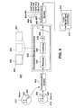
- FIG. 4 illustrates a wind turbine control system 400 with a controller, referred to as a "coordinated windfarm controller” that may be used to limit voltage oscillations occurring in a transmission system, such as the one illustrated in FIG. 3 .
- Measurement of system parameters may be obtained from the system at measurements points at a plurality of locations. The measurement points may be represented by a first point 401 and a second point 402 representative of area 1 403 and area 2 404, respectively. The measurements described above may be provided as synchronized phasors.
- Measurement instruments 405 sense system parameters and provide the measurements to a communications network 415 for transmittal to the coordinated windfarm controller 430.
- An embodiment of the coordinated windfarm controller 430 includes an implementation for algorithm, may contain a washout filter element 435, a lead-lag compensator 440 and a gain 445 with output limiter 450.
- the washout filter 435 is a high pass filter that rejects steady state and very low frequency inputs, while passing transient of medium to high frequency inputs. It is used so that the controller does not affect the steady state operating point of the system, but instead to allow modifications around the operating point. Additional filters such as low pass filters can be included.
- the lead-lag compensator 440 is a filter that is designed to advance or retard the phase of frequency components at the desired frequencies and is applied to improve damping characteristics within the feedback control circuit.
- the gain 445 represented by value K is the ratio of output to input signal.
- the saturation component 450 produces an output identical the input value unless the input is greater than some upper predefined limit or less than a lower predefined limit, in which case the output is set to the upper or lower limit respectively.
- Output 460 of the coordinated windfarm controller 430 is then transmitted by the communications network 425 to the local windfarm controller 410.
- the output signal 430 could be at least one of a windfarm voltage reference change ( ⁇ Vref(WP)) 460, windfarm reactive power reference change ( ⁇ Qref(WP)) 465, individual wind turbine voltage reference change ( ⁇ Vref(WT)) 470, an a individual wind turbine reactive power reference change ( ⁇ Qref(WT)) 475, or in other formats useful for a windfarm control system (such as described in Larsen, in US Patents No. 7,119,452 , No. 7,166,928 , and No. 7,224,081 ).
- the above-described embodiment describes the control for a single windfarm 475, but such control may be extended to multiple windfarms.
- the coordinated windfarm controller 430 may be located physically on a computer system 480 incorporated as part of a windfarm management system 485 which may be present at the windfarm 475, physically located on a computer system of the utility system operator 490, or it maybe be implemented on an independent computer system 495.
- application of the inventive stability controls for transmission line voltage exercised through control of wind farms connected to the transmission network may extend the operation of the transmission system, preventing voltage collapse.
- the capacity of the system to transmit power before the onset of voltage collapse is extended (dashed line) 195 to Pmax2 198.
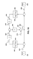
- FIG. 5 illustrates an embodiment of an inventive coordinated windfarm controller that may be used to limit voltage oscillations occurring in a transmission system, such as the one illustrated in FIG. 1 .
- Fig. 5 represents an extension of the case of Fig. 4 where control is extended to multiple windfarms. Not shown are the detailed elements included in the controller but essentially the functions of the controller in Fig. 4 are extended to the multiple inputs and outputs case.
- the coordinated windfarm control system 500 includes a plurality of local windfarm controllers, represented as windfarm controller 1 571, windfarm controller 2 572, and windfarm controller n 575 to provide stability control a transmission grid.
- the coordinated windfarm control system 500 is not limited to control of any specific number of windfarms.
- the coordinated windfarm controller 500 receives a plurality of measurement sets (represented as measurement set 1 511, measurement set 2 512, Across, measurement set n 515).
- Each of the measurement sets may include transmission system parameters, which may include (P, Q, I, ⁇ , ⁇ i and V i ) from a plurality of different measurement points 520, 521, Across 525 on the transmission network.
- Measurement sets 511, 512, ??, 515 are transmitted by a communication network 525 from sensors 531, 532, ....535 at the measure points to the coordinated windfarm controller 550.
- Outputs signals from the coordinated windfarm controller 550 are transmitted by the communication network 545 to the respective windfarms controller 571, 572 ... 575.
- the output of the coordinated controller provides control signals for m different windfarms so as to improve damping of electromechanical oscillations on the transmission line.
- the elements of the coordinated controller may include a washout filter extended to the multi-input multi-output case, a filter exhibiting properties of the lead-lag filter in Fig 4 (multi-input multi-output), an amplification matrix, and saturation limits on the outputs.
- the multiple control signals to the windfarms may include at least one of a windfarm voltage reference change ( ⁇ Vref(WP)) 460, windfarm reactive power reference change ( ⁇ Qref(WP)) 465, individual wind turbine voltage reference change ( ⁇ Vref(WT)) 470, an a individual wind turbine reactive power reference change ( ⁇ Qref(WT)) 475, previously described with respect to single windfarm controller 430 of FIG. 4 .
- FIG. 6 illustrates an embodiment of an inventive coordinated controller providing control for wind turbines and associated reactive control devices within multiple wind farms.
- the coordinated system controller 605 provides outputs for control of a plurality of system reactive control devices, in addition to the stabilizing control signal 665 to windfarms 695.
- Such reactive control devices may include passive shunt capacitors 670 and on load tap changers 675.
- the inputs are a reference voltage (Vref) 610 which may be preprogrammed or set by the utility system operator and can be updated from time to time. (Vref) 610 is compared to a measurement of voltage (Vremote) 625 which is from a defined point P1 626 on the transmssion system and may be remote from any point P2 696 from which the windfarms 695 connected to the network the system.
- Vref reference voltage
- Vremote a measurement of voltage
- the coordinated systen controller 605 may include a proportional-integral (P+I) regulator algorithm (filter) 630 and then a distribution algorithm (Network Solutions) 640 whose technical effect is to supply command signals to one or more windfarms and/or passive devices such as the shunt capacitors 670 and on-load tap changers 675.
- the limitations 645 may include reactive power and voltage for the various windfarms and nodes of the transmission grid may be considered in the processing of the algorithm.
- the command signals to the windfarms may include reactive power reference (Qref(WP)) 680 or voltage reference (Vref(WP) 685).
- FIG. 7 illustrates a schematic representation for a transmission network including two areas with both power generation capability and load supply capability connected to a windfarm.
- Generator transmission/load area 1 710 and area 2 720 are connected by transmission lines 725 which include reactance 723.
- a plurality of wind turbine generators 740 are connected through connection transformers 745 to collection bus 750.
- Collection bus is tied to a point of common connection 715 through main transformer 755.
- Generator transmission/load area 1 710 and generator transmission/load area 2 720 supply local area loads PL1 724 and PL2 725, respectively.
- Generator transmission/load area 1 710 and generator transmission/load area 2 720 provide output voltages of E1 at reference angle ⁇ 1 and output voltage of E2 at reference angle ⁇ 2, respectively.
- FIG. 8 illustrates a Laplace block-diagram representation of the network of FIG. 7 for small signal analysis of electromechanical oscillation.
- M1 and M2 represent the equivalent inertia of area 1 and area 2, respectively.
- D1 and D2 represent load-damping constants of area 1 and area 2, respectively.
- E1 and E2 represent the voltage magnitudes for area 1 and area 2, respectively.
- ⁇ 1 and ⁇ 2 represent the voltage angle with respect to the same reference for area 1 and area 2, respectively.
- PL1 and PL2 represent load power consumption in area 1 and area 2, respectively.
- ⁇ 1 and ⁇ 2 represent frequency of area 1 and area 2, respectively.
- X represents the effective total reactance between area 1 and area 2.
- ⁇ 1o and ⁇ 2o represent the initial voltage angle with respect to the same reference.
- a differential power flow is driven between area 1 and area 2.
- the differential power flow between area 1 and area 2 must be strong enough to maintain the two areas in synchronism.
- the differential power flow may be damped out, may oscillate, or may grow to a point where system trips occur.
- FIGs. 9A-9C illustrates a time simulation of a load switching event of the transmission network of FIG. 7 without a stabilizing loop.
- FIG. 9A illustrates a transient response for current 910 flowing between areas.
- FIG. 9B illustrates a transient response for power 920 flowing between areas.
- FIG. 9C illustrates a response for voltage 930 at the point of connection (POC) between the windfarm and the grid ( FIG. 7 ).
- the transient is initiated by a load shift at T1 940 initiating an oscillation of resonant mode for the current 910, power 920 and voltage 930. Peak amplitudes A 1 970, A 2 975 and A 3 980 of the oscillations for current, power and voltage are shown.
- FIG. 10 illustrates a Laplace block-diagram representation of networks for small signal analysis of electromechanical oscillation, including a stabilizing loop.
- the Laplace small signal model of FIG. 8 may be modified by incorporating a synchronizing power flow ⁇ P s 888 added to the output of torque generating block T 880 at summer 890 to produce a modified differential power flow ⁇ P 12 895.
- the new synchronizing power flow ⁇ P s 888 may be generated with the inventive windfarm controller.
- FIG. 11 illustrates an embodiment of an inventive windfarm coordinated controller incorporating a stabilizing loop for improved damping of network electromechanical oscillation.
- System parameters (I 1 , V 1 , ⁇ 1 and P 1 ) and (I 2 , V 2 , ⁇ 2 and P 2 ) may be measured by a wide area measurement system as in FIG. 2 and FIG3 .
- ⁇ I 12 1120 (current flow from area 1 to area 2) may be inferred from differential power flow ⁇ P 12 1110 and Eo 115.
- ⁇ I 12 1120 may be applied to coordinated windfarm controller 1140 including washout filter 1141, lead-lag filter 1142, gain factor 1143, and system limiter 1144 to provide a ⁇ Q ref 1150 to be transmitted to the local windfarm controller 1160 for windfarm 1170 within the transmission system to stabilize oscillations.
- the windfarm 1170 may generate a differential voltage output ⁇ V, resulting in a differential current output ⁇ Io 1185, providing a differential power output to the transmission network ⁇ P s 1190.
- FIGs. 12A-12D illustrates a time simulation of a load switching event of the transmission network of FIG. 7 incorporating an embodiment of the inventive stabilizing loop.
- FIG. 12A illustrates a transient response for current 1210 flowing between areas.
- FIG. 12B illustrates a transient response for power 1220 flowing between areas.
- FIG. 12C illustrates a response for voltage 1230 at the point of connection (POC) between the windfarm and the grid ( FIG. 7 ).
- FIG. 12D illustrates a reactive power command 1250 incorporating the stabilizing loop of FIG. 11 .
- the transient is initiated by a load shift at T1 1250 initiating a damped oscillatory response for the current 1210, power 1220 and voltage 1230. Peak amplitudes of the transient response 1270, 1275 and 1280 for current, power and voltage are significantly reduced over the peak amplitudes for oscillations 970, 975 and 980 of the unstabilized system of FIG. 9A-9C .
- windfarm power controls can be further exploited by making use of wide-area measurements and high bandwidth communication networks.
- wide-area measurements and high bandwidth communication networks Considering a single instance of a windfarm, the capability to provide reactive power at the point of interconnection using the power electronic converter of each turbine, can improve damping and voltage performance.
- An additional term to these controllers incorporating wide-are measurements is used to improve system stability.
- a set of windfarms with a coordinated set of controller settings, with each windfarm supplied by a small number of possibly different wide-are measurements could further improve the overall system performance.
- An alternative approach includes a centralized controller with access to network-wide measurements and high bandwidth controller to windfarm communications for actuation signals.
Landscapes
- Engineering & Computer Science (AREA)
- Power Engineering (AREA)
- Life Sciences & Earth Sciences (AREA)
- Sustainable Development (AREA)
- Sustainable Energy (AREA)
- Chemical & Material Sciences (AREA)
- Combustion & Propulsion (AREA)
- Mechanical Engineering (AREA)
- General Engineering & Computer Science (AREA)
- Control Of Eletrric Generators (AREA)
- Wind Motors (AREA)
Applications Claiming Priority (1)
| Application Number | Priority Date | Filing Date | Title |
|---|---|---|---|
| US12/262,951 US8058753B2 (en) | 2008-10-31 | 2008-10-31 | Wide area transmission control of windfarms |
Publications (4)
| Publication Number | Publication Date |
|---|---|
| EP2182207A2 true EP2182207A2 (fr) | 2010-05-05 |
| EP2182207A3 EP2182207A3 (fr) | 2012-08-08 |
| EP2182207B1 EP2182207B1 (fr) | 2013-12-25 |
| EP2182207B2 EP2182207B2 (fr) | 2022-01-19 |
Family
ID=41818344
Family Applications (1)
| Application Number | Title | Priority Date | Filing Date |
|---|---|---|---|
| EP09173575.3A Active EP2182207B2 (fr) | 2008-10-31 | 2009-10-21 | Commande de transmission de zone étendue de parcs éoliens |
Country Status (5)
| Country | Link |
|---|---|
| US (1) | US8058753B2 (fr) |
| EP (1) | EP2182207B2 (fr) |
| CN (1) | CN101725480B (fr) |
| DK (1) | DK2182207T4 (fr) |
| ES (1) | ES2447569T5 (fr) |
Cited By (16)
| Publication number | Priority date | Publication date | Assignee | Title |
|---|---|---|---|---|
| US8058753B2 (en) * | 2008-10-31 | 2011-11-15 | General Electric Company | Wide area transmission control of windfarms |
| WO2012000514A3 (fr) * | 2010-06-30 | 2012-03-22 | Vestas Wind Systems A/S | Système, procédé et produit de programme informatique destinés à utiliser un parc éolien comme stabilisateur de système d'énergie variable |
| WO2012041543A1 (fr) * | 2010-09-28 | 2012-04-05 | Siemens Aktiengesellschaft | Dispositif de commande d'amortissement d'oscillation de puissance |
| WO2013004252A3 (fr) * | 2011-09-30 | 2013-10-24 | Vestas Wind Systems A/S | Dispositif de commande pour l'atténuation d'oscillations du réseau |
| WO2015078474A1 (fr) * | 2013-11-28 | 2015-06-04 | Vestas Wind Systems A/S | Dispositif de commande de centrale électrique pour générer une référence de puissance pour des générateurs d'éoliennes |
| EP2636894A3 (fr) * | 2012-03-06 | 2015-07-01 | RWE Innogy GmbH | Système d'éolienne offshore |
| EP2945278A1 (fr) * | 2014-05-12 | 2015-11-18 | Alstom Technology Ltd | Système d'excitation statique pour générateurs |
| EP3005515A4 (fr) * | 2013-12-06 | 2017-05-17 | Rajiv Kumar Varma | Contrôleur de modulateur multivariable pour installation de génération d'énergie |
| WO2017210124A1 (fr) * | 2016-05-28 | 2017-12-07 | PXiSE Energy Solutions, LLC | Système de commande à base de synchrophaseur de découplage pour ressources d'énergie réparties |
| US10424935B2 (en) | 2009-09-15 | 2019-09-24 | Rajiv Kumar Varma | Multivariable modulator controller for power generation facility |
| US10452032B1 (en) | 2016-09-08 | 2019-10-22 | PXiSE Energy Solutions, LLC | Optimizing power contribution of distributed energy resources for real time power demand scheduling |
| US10599175B1 (en) | 2017-02-28 | 2020-03-24 | PXiSE Energy Solutions, LLC | Time synchronized frequency and voltage regulation of electric power balancing areas |
| US10615604B2 (en) | 2016-05-28 | 2020-04-07 | PXiSE Energy Solutions, LLC | Decoupling synchrophasor based control system for distributed energy resources |
| US10990072B2 (en) | 2017-11-28 | 2021-04-27 | PXiSE Energy Solutions, LLC | Maintaining power grid stability using predicted data |
| US11056912B1 (en) | 2021-01-25 | 2021-07-06 | PXiSE Energy Solutions, LLC | Power system optimization using hierarchical clusters |
| CN116545037A (zh) * | 2023-07-03 | 2023-08-04 | 广东电网有限责任公司中山供电局 | 一种面向分布式资源集群的轻量化边缘控制方法及装置 |
Families Citing this family (44)
| Publication number | Priority date | Publication date | Assignee | Title |
|---|---|---|---|---|
| WO2008137836A1 (fr) * | 2007-05-04 | 2008-11-13 | The University Of Alabama | Commande de convertisseur d'éoliennes à vitesse variable |
| EP2242159B1 (fr) * | 2009-04-17 | 2016-04-13 | Vestas Wind Systems A/S | Parc éolien, procédé de correction de déséquilibres de tension et turbine d'éolienne |
| ES2586334T3 (es) * | 2009-08-21 | 2016-10-13 | Vestas Wind Systems A/S | Sistema y método para monitorizar filtros de potencia y detectar un fallo de filtro de potencia en un generador eléctrico de turbina eólica |
| US8227929B2 (en) * | 2009-09-25 | 2012-07-24 | General Electric Company | Multi-use energy storage for renewable sources |
| JP5320311B2 (ja) * | 2010-01-18 | 2013-10-23 | 三菱重工業株式会社 | 可変速発電装置及びその制御方法 |
| ES2613869T3 (es) * | 2010-01-26 | 2017-05-26 | Vestas Wind Systems A/S | Método para la emulación de una máquina síncrona |
| WO2011150932A2 (fr) * | 2010-06-03 | 2011-12-08 | Vestas Wind Systems A/S | Procédé et agencement de commande pour la commande de condensateurs centraux dans des centrales éoliennes |
| US9391554B2 (en) | 2010-08-25 | 2016-07-12 | University Of Alabama | Control of a permanent magnet synchronous generator wind turbine |
| US20120175962A1 (en) * | 2011-01-11 | 2012-07-12 | Converteam Technology Ltd. | Power Collection and Transmission Systems |
| CN102624023B (zh) * | 2011-01-31 | 2014-07-09 | 华锐风电科技(集团)股份有限公司 | 双馈型机组风电场的无功电压控制系统 |
| US8977403B2 (en) * | 2011-06-22 | 2015-03-10 | Mitsubishi Heavy Industries, Ltd. | Remote monitoring apparatus, wind turbine generator system, and method of controlling remote monitoring apparatus |
| WO2013037846A1 (fr) * | 2011-09-12 | 2013-03-21 | Alstom Technology Ltd | Amortissement d'oscillation sous-synchrone par un appareil à dérivation |
| WO2013071098A1 (fr) * | 2011-11-11 | 2013-05-16 | Power Quality Renaissance, Llc | Suivi réactif pour génération distribuée et charges d'une ou plusieurs autres unités de commande réactives |
| US9201410B2 (en) | 2011-12-23 | 2015-12-01 | General Electric Company | Methods and systems for optimizing farm-level metrics in a wind farm |
| RU2482588C1 (ru) * | 2012-04-06 | 2013-05-20 | Открытое акционерное общество "Федеральная сетевая компания Единой энергетической системы" | Устройство формирования синхронизированных данных о состоянии энергообъекта |
| CN102624010A (zh) * | 2012-04-19 | 2012-08-01 | 四川电力科学研究院 | 一种适用于交直流混联外送电网的动态无功补偿控制方法 |
| EP2841766B1 (fr) * | 2012-04-27 | 2021-06-02 | Siemens Gamesa Renewable Energy Service GmbH | Parc éolien permettant une régulation locale rapide de la puissance réactive |
| IN2015DN02395A (fr) * | 2012-09-17 | 2015-09-04 | Vestas Wind Sys As | |
| WO2014056504A2 (fr) * | 2012-10-08 | 2014-04-17 | Vestas Wind Systems A/S | Système de compensation d'impédance de ligne |
| US9680307B2 (en) * | 2012-12-21 | 2017-06-13 | General Electric Company | System and method for voltage regulation of a renewable energy plant |
| US9203333B2 (en) * | 2013-09-05 | 2015-12-01 | General Electric Company | System and method for voltage control of wind generators |
| US10411472B2 (en) | 2013-10-22 | 2019-09-10 | Abb Schweiz Ag | Method for controlling electrical power in a microgrid and arrangement comprising distributed generators |
| EP2869419B1 (fr) * | 2013-10-29 | 2019-10-02 | General Electric Technology GmbH | Réseau de transmission de puissance |
| US9828971B2 (en) * | 2014-11-20 | 2017-11-28 | General Electric Company | System and method for optimizing wind turbine operation |
| GB201507349D0 (en) | 2015-04-29 | 2015-06-10 | Alstom Grid Uk Ltd | Control of an electrical power network |
| WO2016177376A1 (fr) * | 2015-05-06 | 2016-11-10 | Vestas Wind Systems A/S | Système de production d'énergie d'éolienne |
| DE102015212562A1 (de) * | 2015-07-06 | 2017-01-12 | Siemens Aktiengesellschaft | Energieerzeugungsanlage und Verfahren zu deren Betrieb |
| CN106844795A (zh) * | 2015-12-03 | 2017-06-13 | 甘肃省电力公司风电技术中心 | 一种风电场内部风向场确认方法 |
| CN105447658A (zh) * | 2016-01-06 | 2016-03-30 | 长沙理工大学 | 一种含风电随机模糊注入电力系统波动的电压崩溃点求取方法 |
| US10027118B2 (en) | 2016-05-19 | 2018-07-17 | General Electric Company | System and method for balancing reactive power loading between renewable energy power systems |
| EP3469679B1 (fr) * | 2016-06-13 | 2022-07-27 | Vestas Wind Systems A/S | Améliorations concernant l'interconnexion de multiples centrales électriques à énergie renouvelable |
| US10418817B2 (en) | 2016-07-29 | 2019-09-17 | Cummins Power Generation Ip, Inc. | Synchronization of parallel gensets with source arbitration |
| US10291028B2 (en) | 2016-07-29 | 2019-05-14 | Cummins Power Generation Ip, Inc. | Masterless distributed power transfer control |
| US9806690B1 (en) * | 2016-09-30 | 2017-10-31 | AEP Transmission Holding Company, LLC | Subsynchronous oscillation relay |
| EP3322061A1 (fr) * | 2016-11-14 | 2018-05-16 | Nordex Energy GmbH | Procédé d'amortissement d'oscillations électromécaniques dans un système électrique |
| ES2776410T3 (es) * | 2016-11-14 | 2020-07-30 | Nordex Energy Gmbh | Método de amortiguación de oscilaciones electromecánicas en un sistema de alimentación |
| US10389125B2 (en) * | 2017-03-07 | 2019-08-20 | Thomas Alexander Wilkins | Expanded reactive following for distributed generation and loads of other reactive controller(s) |
| US10428797B2 (en) * | 2017-07-05 | 2019-10-01 | Inventus Holdings, Llc | Wind farm power regulation |
| US10720773B2 (en) * | 2018-01-02 | 2020-07-21 | City University Of Hong Kong | Electric circuit and associated method for regulating power transfer in a power grid |
| US11063441B2 (en) | 2018-10-18 | 2021-07-13 | General Electric Company | Systems and methods for managing resonance in wind turbine power systems |
| WO2020214913A1 (fr) * | 2019-04-18 | 2020-10-22 | University Of Washington | Systèmes et procédés de stabilisation de système électrique et de commande d'amortissement d'oscillation |
| EP3734799A1 (fr) * | 2019-05-02 | 2020-11-04 | Siemens Gamesa Renewable Energy A/S | Pilotage d'une éolienne et sa méthode |
| EP3866293A3 (fr) | 2020-01-21 | 2021-12-01 | Vestas Wind Systems A/S | Procédé de commande d'éolienne |
| US11726436B2 (en) * | 2021-08-19 | 2023-08-15 | General Electric Renovables Espana, S.L. | System and method for controlling a power generating system |
Citations (1)
| Publication number | Priority date | Publication date | Assignee | Title |
|---|---|---|---|---|
| US7119452B2 (en) | 2003-09-03 | 2006-10-10 | General Electric Company | Voltage control for wind generators |
Family Cites Families (30)
| Publication number | Priority date | Publication date | Assignee | Title |
|---|---|---|---|---|
| US4400659A (en) * | 1980-05-30 | 1983-08-23 | Benjamin Barron | Methods and apparatus for maximizing and stabilizing electric power derived from wind driven source |
| US6600240B2 (en) * | 1997-08-08 | 2003-07-29 | General Electric Company | Variable speed wind turbine generator |
| NL1009543C2 (nl) * | 1998-07-02 | 2000-01-07 | Lagerwey Windturbine B V | Inrichting voor het omzetten van windenergie in elektrische energie. |
| JP3755075B2 (ja) * | 1999-01-22 | 2006-03-15 | 株式会社日立製作所 | 電力変動補償装置 |
| SE514934C2 (sv) * | 1999-09-06 | 2001-05-21 | Abb Ab | Anläggning för generering av elektrisk effekt med hjälp av vindkraftspark samt förfarande för drift av en sådan anlägning. |
| WO2001091279A1 (fr) * | 2000-05-23 | 2001-11-29 | Vestas Wind Systems A/S | Eolienne a vitesse variable pourvue d'un convertisseur de matrice |
| US20020084655A1 (en) * | 2000-12-29 | 2002-07-04 | Abb Research Ltd. | System, method and computer program product for enhancing commercial value of electrical power produced from a renewable energy power production facility |
| TR201807396T4 (tr) * | 2001-04-20 | 2018-06-21 | Wobben Properties Gmbh | Bir rüzgar enerjisi santralinin çalıştırılması için yöntem. |
| JP5216181B2 (ja) * | 2001-09-28 | 2013-06-19 | アロイス・ヴォベン | ウインドパークの運転方法 |
| JP2003169500A (ja) * | 2001-11-30 | 2003-06-13 | Mitsubishi Electric Corp | 同期機の励磁制御装置 |
| US7015595B2 (en) * | 2002-02-11 | 2006-03-21 | Vestas Wind Systems A/S | Variable speed wind turbine having a passive grid side rectifier with scalar power control and dependent pitch control |
| DE10210099A1 (de) * | 2002-03-08 | 2003-10-02 | Aloys Wobben | Inselnetz und Verfahren zum Betrieb eines Inselnetzes |
| US7071579B2 (en) * | 2002-06-07 | 2006-07-04 | Global Energyconcepts,Llc | Wind farm electrical system |
| WO2004025803A1 (fr) * | 2002-09-13 | 2004-03-25 | Abb Ab | Reseau alimente par energie eolienne |
| US6858953B2 (en) * | 2002-12-20 | 2005-02-22 | Hawaiian Electric Company, Inc. | Power control interface between a wind farm and a power transmission system |
| US6924565B2 (en) * | 2003-08-18 | 2005-08-02 | General Electric Company | Continuous reactive power support for wind turbine generators |
| JP4269941B2 (ja) * | 2004-01-08 | 2009-05-27 | 株式会社日立製作所 | 風力発電装置およびその制御方法 |
| JP3918837B2 (ja) * | 2004-08-06 | 2007-05-23 | 株式会社日立製作所 | 風力発電装置 |
| DE102004048341A1 (de) † | 2004-10-01 | 2006-04-13 | Repower Systems Ag | Windpark mit robuster Blindleistungsregelung und Verfahren zum Betrieb |
| WO2006127844A2 (fr) * | 2005-05-24 | 2006-11-30 | Satcon Technology Corporation | Dispositif, systeme, et procede de fourniture d'une periode de grace anti panne basse tension a parc a eoliennes |
| US20070124025A1 (en) * | 2005-11-29 | 2007-05-31 | General Electric Company | Windpark turbine control system and method for wind condition estimation and performance optimization |
| DK1914420T3 (en) * | 2006-10-19 | 2015-08-24 | Siemens Ag | Wind energy installation and method for controlling the output power from a wind power installation |
| GB2444528B (en) * | 2006-12-09 | 2011-07-06 | Converteam Ltd | Methods for synchronising a plurality of generators |
| US20090055030A1 (en) * | 2007-08-21 | 2009-02-26 | Ingeteam, S.A. | Control of active power reserve in a wind-farm |
| CN100476651C (zh) * | 2007-08-23 | 2009-04-08 | 上海交通大学 | 大型海上风力发电场监控系统 |
| US20090160187A1 (en) * | 2007-12-19 | 2009-06-25 | Scholte-Wassink Hartmut | Control system and method for operating a wind farm in a balanced state |
| US7994658B2 (en) * | 2008-02-28 | 2011-08-09 | General Electric Company | Windfarm collector system loss optimization |
| US7839024B2 (en) * | 2008-07-29 | 2010-11-23 | General Electric Company | Intra-area master reactive controller for tightly coupled windfarms |
| US8058753B2 (en) * | 2008-10-31 | 2011-11-15 | General Electric Company | Wide area transmission control of windfarms |
| US7999418B2 (en) * | 2008-12-22 | 2011-08-16 | General Electric Company | Electrical system and control method |
-
2008
- 2008-10-31 US US12/262,951 patent/US8058753B2/en active Active
-
2009
- 2009-10-21 ES ES09173575T patent/ES2447569T5/es active Active
- 2009-10-21 EP EP09173575.3A patent/EP2182207B2/fr active Active
- 2009-10-21 DK DK09173575.3T patent/DK2182207T4/da active
- 2009-10-30 CN CN2009102088923A patent/CN101725480B/zh active Active
Patent Citations (3)
| Publication number | Priority date | Publication date | Assignee | Title |
|---|---|---|---|---|
| US7119452B2 (en) | 2003-09-03 | 2006-10-10 | General Electric Company | Voltage control for wind generators |
| US7166928B2 (en) | 2003-09-03 | 2007-01-23 | General Electric Company | Voltage control for wind generators |
| US7224081B2 (en) | 2003-09-03 | 2007-05-29 | General Electric Company | Voltage control for wind generators |
Non-Patent Citations (2)
| Title |
|---|
| "Proc. 38th Hawaii Intl. Conf. System Sciences", 2005, article "A Real-Time Wide-Area Control Framework for Mitigating Small-Signal Instability in Large Electric Power Systems" |
| KAMWA; GRONDIN; HEBERT: "IEEE Trans. Power Systems", vol. 16, February 2001, article "Wide-Area Measurements Based Stabilizing Control of Large Power Systems - A Decentralized/Hierarchical Approach", pages: 136 - 152 |
Cited By (34)
| Publication number | Priority date | Publication date | Assignee | Title |
|---|---|---|---|---|
| US8058753B2 (en) * | 2008-10-31 | 2011-11-15 | General Electric Company | Wide area transmission control of windfarms |
| US10424935B2 (en) | 2009-09-15 | 2019-09-24 | Rajiv Kumar Varma | Multivariable modulator controller for power generation facility |
| US11271405B2 (en) | 2009-09-15 | 2022-03-08 | Rajiv Kumar Varma | Multivariable modulator controller for power generation facility |
| WO2012000514A3 (fr) * | 2010-06-30 | 2012-03-22 | Vestas Wind Systems A/S | Système, procédé et produit de programme informatique destinés à utiliser un parc éolien comme stabilisateur de système d'énergie variable |
| US8618694B2 (en) | 2010-06-30 | 2013-12-31 | Vestas Wind Systems A/S | System, method, and computer program product for utilizing a wind park as a variable power system stabilizer |
| US9528499B2 (en) | 2010-09-28 | 2016-12-27 | Siemens Aktiengesellschaft | Power oscillation damping controller |
| WO2012041543A1 (fr) * | 2010-09-28 | 2012-04-05 | Siemens Aktiengesellschaft | Dispositif de commande d'amortissement d'oscillation de puissance |
| EP2594004B1 (fr) * | 2010-09-28 | 2015-03-04 | Siemens Aktiengesellschaft | Amortissement d'oscillation d'énergie électrique par un dispositif de production d'énergie électrique à base de convertisseur |
| US9133825B2 (en) | 2010-09-28 | 2015-09-15 | Siemens Aktiengesellschaft | Power oscillation damping by a converter-based power generation device |
| WO2013004252A3 (fr) * | 2011-09-30 | 2013-10-24 | Vestas Wind Systems A/S | Dispositif de commande pour l'atténuation d'oscillations du réseau |
| US9647457B2 (en) | 2011-09-30 | 2017-05-09 | Vestas Wind Systems A/S | Control device for damping grid oscillations |
| EP3101274A1 (fr) * | 2012-03-06 | 2016-12-07 | RWE Innogy GmbH | Systeme d'eolienne |
| EP2636894A3 (fr) * | 2012-03-06 | 2015-07-01 | RWE Innogy GmbH | Système d'éolienne offshore |
| US11401917B2 (en) | 2013-11-28 | 2022-08-02 | Vestas Wind Systems A/S | Power plant controller for generating a power reference to wind turbine generators |
| WO2015078474A1 (fr) * | 2013-11-28 | 2015-06-04 | Vestas Wind Systems A/S | Dispositif de commande de centrale électrique pour générer une référence de puissance pour des générateurs d'éoliennes |
| US10539117B2 (en) | 2013-11-28 | 2020-01-21 | Vestas Wind Systems A/S | Power plant controller for generating a power reference to wind turbine generators |
| EP3005515B1 (fr) | 2013-12-06 | 2020-06-24 | Rajiv Kumar Varma | Contrôleur de modulateur multivariable pour installation de génération d'énergie |
| EP3005515A4 (fr) * | 2013-12-06 | 2017-05-17 | Rajiv Kumar Varma | Contrôleur de modulateur multivariable pour installation de génération d'énergie |
| EP3745550A1 (fr) * | 2013-12-06 | 2020-12-02 | Rajiv Kumar Varma | Commande modulateur à variables multiples pour installation de génération d'énergie |
| US9735719B2 (en) | 2014-05-12 | 2017-08-15 | General Electric Technology Gmbh | Static exciter system for generators |
| EP2945278A1 (fr) * | 2014-05-12 | 2015-11-18 | Alstom Technology Ltd | Système d'excitation statique pour générateurs |
| US10027119B2 (en) | 2016-05-28 | 2018-07-17 | PXiSE Energy Solutions, LLC | Decoupling synchrophasor based control system for multiple distributed energy resources |
| US10615604B2 (en) | 2016-05-28 | 2020-04-07 | PXiSE Energy Solutions, LLC | Decoupling synchrophasor based control system for distributed energy resources |
| US10714938B2 (en) | 2016-05-28 | 2020-07-14 | PXiSE Energy Solutions, LLC | Decoupling synchrophasor based control system for multiple distributed energy resources |
| AU2017273433B2 (en) * | 2016-05-28 | 2020-10-08 | PXiSE Energy Solutions, LLC | Decoupling synchrophasor based control system for distributed energy resources |
| GB2566184B (en) * | 2016-05-28 | 2021-11-10 | Pxise Energy Solutions Llc | Decoupling synchrophasor based control system for distributed energy resources |
| GB2566184A (en) * | 2016-05-28 | 2019-03-06 | Pxise Energy Solutions Llc | Decoupling synchrophasor based control system for distributed energy resources |
| WO2017210124A1 (fr) * | 2016-05-28 | 2017-12-07 | PXiSE Energy Solutions, LLC | Système de commande à base de synchrophaseur de découplage pour ressources d'énergie réparties |
| US10452032B1 (en) | 2016-09-08 | 2019-10-22 | PXiSE Energy Solutions, LLC | Optimizing power contribution of distributed energy resources for real time power demand scheduling |
| US10599175B1 (en) | 2017-02-28 | 2020-03-24 | PXiSE Energy Solutions, LLC | Time synchronized frequency and voltage regulation of electric power balancing areas |
| US10990072B2 (en) | 2017-11-28 | 2021-04-27 | PXiSE Energy Solutions, LLC | Maintaining power grid stability using predicted data |
| US11056912B1 (en) | 2021-01-25 | 2021-07-06 | PXiSE Energy Solutions, LLC | Power system optimization using hierarchical clusters |
| CN116545037A (zh) * | 2023-07-03 | 2023-08-04 | 广东电网有限责任公司中山供电局 | 一种面向分布式资源集群的轻量化边缘控制方法及装置 |
| CN116545037B (zh) * | 2023-07-03 | 2023-09-26 | 广东电网有限责任公司中山供电局 | 一种面向分布式资源集群的轻量化边缘控制方法及装置 |
Also Published As
| Publication number | Publication date |
|---|---|
| EP2182207B2 (fr) | 2022-01-19 |
| EP2182207B1 (fr) | 2013-12-25 |
| US20100109447A1 (en) | 2010-05-06 |
| US8058753B2 (en) | 2011-11-15 |
| ES2447569T3 (es) | 2014-03-12 |
| CN101725480A (zh) | 2010-06-09 |
| DK2182207T4 (da) | 2022-04-11 |
| ES2447569T5 (es) | 2022-05-09 |
| EP2182207A3 (fr) | 2012-08-08 |
| CN101725480B (zh) | 2013-05-08 |
| DK2182207T3 (da) | 2014-02-10 |
Similar Documents
| Publication | Publication Date | Title |
|---|---|---|
| EP2182207B1 (fr) | Commande de transmission de zone étendue de parcs éoliens | |
| Nieto et al. | Power quality improvement in power grids with the integration of energy storage systems | |
| Gevorgian et al. | Review of PREPA technical requirements for interconnecting wind and solar generation | |
| Sørensen et al. | Wind farm models and control strategies | |
| Krishnan et al. | A robust decentralized wide area damping controller for wind generators and FACTS controllers considering load model uncertainties | |
| CN102280879B (zh) | 风电场大规模储能电站功率调节方法及系统 | |
| Rodriguez-Amenedo et al. | Operation and coordinated control of fixed and variable speed wind farms | |
| Zhang et al. | Wind power transmission through LCC-HVDC with wind turbine inertial and primary frequency supports | |
| CN106300427A (zh) | 一种统一潮流控制器在风电机组并网运行中应用的方法 | |
| Zhang et al. | Research overview of sub-synchronous oscillation in DFIG-BASED wind farms connected to grid | |
| Subburaja et al. | Battery connected DFIG wind system analysis for strong/weak grid scenarios | |
| Yan et al. | Analysis of SSO characteristics of D-PMSGs based wind farm under weak AC system | |
| Gevorgian et al. | Wgrid-49 GMLC project report: Understanding the role of short-term energy storage and large motor loads for active power controls by wind power | |
| Sajadi et al. | Great Lakes O Shore Wind Project: Utility and Regional Integration Study | |
| Aluko | Modelling and performance analysis of doubly fed induction generator wind farm | |
| Wu et al. | State-of-the-art review on frequency and voltage regulation techniques from wind farms | |
| Sabo et al. | A Review of Power System Oscillations for a Grid-Connected Photovoltaic (PV) System | |
| Lallu | REACTIVE POWER MANAGEMENT OF DISTRIBUTION NETWORKS USING DISTRIBUTED ENERGY SOURCES FOR IMPROVING POWER SYSTEM STABILITY | |
| Kaberere | Analysis Of The Impact Of Wind Power Generation On The Kenyan Power System’s Small Signal Stability Mkabane Cherema Cynthia | |
| Ekstrand et al. | Stability Related Issues for High Wind Power Penetration: Exploring possibilities to enhance grid stability from synthetic inertia in a future scenario | |
| Tahaguas | Modeling and simulation of power system dynamics for studying the impacts of increasing wind power in a weak grid system | |
| Woldu | Modeling and simulation of power system dynamics for studying the impacts of increasing wind power in a weak grid system | |
| Peters | Control of Non-Synchronous Generating Plants to Improve Stability in Weak Grid Environments | |
| Badreldien | Modern Control of Smart Power Grids | |
| Baldwin | Control System Architecture |
Legal Events
| Date | Code | Title | Description |
|---|---|---|---|
| PUAI | Public reference made under article 153(3) epc to a published international application that has entered the european phase |
Free format text: ORIGINAL CODE: 0009012 |
|
| AK | Designated contracting states |
Kind code of ref document: A2 Designated state(s): AT BE BG CH CY CZ DE DK EE ES FI FR GB GR HR HU IE IS IT LI LT LU LV MC MK MT NL NO PL PT RO SE SI SK SM TR |
|
| AX | Request for extension of the european patent |
Extension state: AL BA RS |
|
| PUAL | Search report despatched |
Free format text: ORIGINAL CODE: 0009013 |
|
| AK | Designated contracting states |
Kind code of ref document: A3 Designated state(s): AT BE BG CH CY CZ DE DK EE ES FI FR GB GR HR HU IE IS IT LI LT LU LV MC MK MT NL NO PL PT RO SE SI SK SM TR |
|
| AX | Request for extension of the european patent |
Extension state: AL BA RS |
|
| RIC1 | Information provided on ipc code assigned before grant |
Ipc: H02J 3/38 20060101ALI20120704BHEP Ipc: F03D 7/02 20060101ALI20120704BHEP Ipc: F03D 7/04 20060101AFI20120704BHEP Ipc: H02J 3/24 20060101ALI20120704BHEP |
|
| 17P | Request for examination filed |
Effective date: 20130208 |
|
| RIC1 | Information provided on ipc code assigned before grant |
Ipc: F03D 7/02 20060101ALI20130702BHEP Ipc: F03D 7/04 20060101AFI20130702BHEP Ipc: H02J 3/38 20060101ALI20130702BHEP Ipc: H02J 3/24 20060101ALI20130702BHEP |
|
| GRAP | Despatch of communication of intention to grant a patent |
Free format text: ORIGINAL CODE: EPIDOSNIGR1 |
|
| INTG | Intention to grant announced |
Effective date: 20130816 |
|
| GRAS | Grant fee paid |
Free format text: ORIGINAL CODE: EPIDOSNIGR3 |
|
| GRAA | (expected) grant |
Free format text: ORIGINAL CODE: 0009210 |
|
| STAA | Information on the status of an ep patent application or granted ep patent |
Free format text: STATUS: THE PATENT HAS BEEN GRANTED |
|
| AK | Designated contracting states |
Kind code of ref document: B1 Designated state(s): AT BE BG CH CY CZ DE DK EE ES FI FR GB GR HR HU IE IS IT LI LT LU LV MC MK MT NL NO PL PT RO SE SI SK SM TR |
|
| REG | Reference to a national code |
Ref country code: GB Ref legal event code: FG4D |
|
| REG | Reference to a national code |
Ref country code: CH Ref legal event code: EP |
|
| REG | Reference to a national code |
Ref country code: AT Ref legal event code: REF Ref document number: 646804 Country of ref document: AT Kind code of ref document: T Effective date: 20140115 |
|
| REG | Reference to a national code |
Ref country code: IE Ref legal event code: FG4D |
|
| REG | Reference to a national code |
Ref country code: DK Ref legal event code: T3 Effective date: 20140204 |
|
| REG | Reference to a national code |
Ref country code: DE Ref legal event code: R096 Ref document number: 602009020939 Country of ref document: DE Effective date: 20140213 |
|
| REG | Reference to a national code |
Ref country code: ES Ref legal event code: FG2A Ref document number: 2447569 Country of ref document: ES Kind code of ref document: T3 Effective date: 20140312 |
|
| PG25 | Lapsed in a contracting state [announced via postgrant information from national office to epo] |
Ref country code: HR Free format text: LAPSE BECAUSE OF FAILURE TO SUBMIT A TRANSLATION OF THE DESCRIPTION OR TO PAY THE FEE WITHIN THE PRESCRIBED TIME-LIMIT Effective date: 20131225 Ref country code: LT Free format text: LAPSE BECAUSE OF FAILURE TO SUBMIT A TRANSLATION OF THE DESCRIPTION OR TO PAY THE FEE WITHIN THE PRESCRIBED TIME-LIMIT Effective date: 20131225 Ref country code: FI Free format text: LAPSE BECAUSE OF FAILURE TO SUBMIT A TRANSLATION OF THE DESCRIPTION OR TO PAY THE FEE WITHIN THE PRESCRIBED TIME-LIMIT Effective date: 20131225 Ref country code: SE Free format text: LAPSE BECAUSE OF FAILURE TO SUBMIT A TRANSLATION OF THE DESCRIPTION OR TO PAY THE FEE WITHIN THE PRESCRIBED TIME-LIMIT Effective date: 20131225 Ref country code: NO Free format text: LAPSE BECAUSE OF FAILURE TO SUBMIT A TRANSLATION OF THE DESCRIPTION OR TO PAY THE FEE WITHIN THE PRESCRIBED TIME-LIMIT Effective date: 20140325 |
|
| REG | Reference to a national code |
Ref country code: NL Ref legal event code: VDEP Effective date: 20131225 |
|
| REG | Reference to a national code |
Ref country code: AT Ref legal event code: MK05 Ref document number: 646804 Country of ref document: AT Kind code of ref document: T Effective date: 20131225 |
|
| REG | Reference to a national code |
Ref country code: LT Ref legal event code: MG4D |
|
| PG25 | Lapsed in a contracting state [announced via postgrant information from national office to epo] |
Ref country code: LV Free format text: LAPSE BECAUSE OF FAILURE TO SUBMIT A TRANSLATION OF THE DESCRIPTION OR TO PAY THE FEE WITHIN THE PRESCRIBED TIME-LIMIT Effective date: 20131225 |
|
| PG25 | Lapsed in a contracting state [announced via postgrant information from national office to epo] |
Ref country code: EE Free format text: LAPSE BECAUSE OF FAILURE TO SUBMIT A TRANSLATION OF THE DESCRIPTION OR TO PAY THE FEE WITHIN THE PRESCRIBED TIME-LIMIT Effective date: 20131225 Ref country code: BE Free format text: LAPSE BECAUSE OF FAILURE TO SUBMIT A TRANSLATION OF THE DESCRIPTION OR TO PAY THE FEE WITHIN THE PRESCRIBED TIME-LIMIT Effective date: 20131225 Ref country code: IS Free format text: LAPSE BECAUSE OF FAILURE TO SUBMIT A TRANSLATION OF THE DESCRIPTION OR TO PAY THE FEE WITHIN THE PRESCRIBED TIME-LIMIT Effective date: 20140425 |
|
| PG25 | Lapsed in a contracting state [announced via postgrant information from national office to epo] |
Ref country code: NL Free format text: LAPSE BECAUSE OF FAILURE TO SUBMIT A TRANSLATION OF THE DESCRIPTION OR TO PAY THE FEE WITHIN THE PRESCRIBED TIME-LIMIT Effective date: 20131225 Ref country code: AT Free format text: LAPSE BECAUSE OF FAILURE TO SUBMIT A TRANSLATION OF THE DESCRIPTION OR TO PAY THE FEE WITHIN THE PRESCRIBED TIME-LIMIT Effective date: 20131225 Ref country code: CY Free format text: LAPSE BECAUSE OF FAILURE TO SUBMIT A TRANSLATION OF THE DESCRIPTION OR TO PAY THE FEE WITHIN THE PRESCRIBED TIME-LIMIT Effective date: 20131225 Ref country code: RO Free format text: LAPSE BECAUSE OF FAILURE TO SUBMIT A TRANSLATION OF THE DESCRIPTION OR TO PAY THE FEE WITHIN THE PRESCRIBED TIME-LIMIT Effective date: 20131225 Ref country code: CZ Free format text: LAPSE BECAUSE OF FAILURE TO SUBMIT A TRANSLATION OF THE DESCRIPTION OR TO PAY THE FEE WITHIN THE PRESCRIBED TIME-LIMIT Effective date: 20131225 Ref country code: PL Free format text: LAPSE BECAUSE OF FAILURE TO SUBMIT A TRANSLATION OF THE DESCRIPTION OR TO PAY THE FEE WITHIN THE PRESCRIBED TIME-LIMIT Effective date: 20131225 Ref country code: SK Free format text: LAPSE BECAUSE OF FAILURE TO SUBMIT A TRANSLATION OF THE DESCRIPTION OR TO PAY THE FEE WITHIN THE PRESCRIBED TIME-LIMIT Effective date: 20131225 Ref country code: PT Free format text: LAPSE BECAUSE OF FAILURE TO SUBMIT A TRANSLATION OF THE DESCRIPTION OR TO PAY THE FEE WITHIN THE PRESCRIBED TIME-LIMIT Effective date: 20140428 |
|
| REG | Reference to a national code |
Ref country code: DE Ref legal event code: R026 Ref document number: 602009020939 Country of ref document: DE |
|
| PLBI | Opposition filed |
Free format text: ORIGINAL CODE: 0009260 |
|
| PLAX | Notice of opposition and request to file observation + time limit sent |
Free format text: ORIGINAL CODE: EPIDOSNOBS2 |
|
| 26 | Opposition filed |
Opponent name: ENERCON GMBH Effective date: 20140925 |
|
| REG | Reference to a national code |
Ref country code: DE Ref legal event code: R026 Ref document number: 602009020939 Country of ref document: DE Effective date: 20140925 |
|
| PLAF | Information modified related to communication of a notice of opposition and request to file observations + time limit |
Free format text: ORIGINAL CODE: EPIDOSCOBS2 |
|
| PLBB | Reply of patent proprietor to notice(s) of opposition received |
Free format text: ORIGINAL CODE: EPIDOSNOBS3 |
|
| PG25 | Lapsed in a contracting state [announced via postgrant information from national office to epo] |
Ref country code: SI Free format text: LAPSE BECAUSE OF FAILURE TO SUBMIT A TRANSLATION OF THE DESCRIPTION OR TO PAY THE FEE WITHIN THE PRESCRIBED TIME-LIMIT Effective date: 20131225 Ref country code: LU Free format text: LAPSE BECAUSE OF FAILURE TO SUBMIT A TRANSLATION OF THE DESCRIPTION OR TO PAY THE FEE WITHIN THE PRESCRIBED TIME-LIMIT Effective date: 20141021 Ref country code: MC Free format text: LAPSE BECAUSE OF FAILURE TO SUBMIT A TRANSLATION OF THE DESCRIPTION OR TO PAY THE FEE WITHIN THE PRESCRIBED TIME-LIMIT Effective date: 20131225 |
|
| REG | Reference to a national code |
Ref country code: CH Ref legal event code: PL |
|
| GBPC | Gb: european patent ceased through non-payment of renewal fee |
Effective date: 20141021 |
|
| REG | Reference to a national code |
Ref country code: IE Ref legal event code: MM4A |
|
| PG25 | Lapsed in a contracting state [announced via postgrant information from national office to epo] |
Ref country code: LI Free format text: LAPSE BECAUSE OF NON-PAYMENT OF DUE FEES Effective date: 20141031 Ref country code: CH Free format text: LAPSE BECAUSE OF NON-PAYMENT OF DUE FEES Effective date: 20141031 Ref country code: GB Free format text: LAPSE BECAUSE OF NON-PAYMENT OF DUE FEES Effective date: 20141021 |
|
| REG | Reference to a national code |
Ref country code: FR Ref legal event code: ST Effective date: 20150630 |
|
| PG25 | Lapsed in a contracting state [announced via postgrant information from national office to epo] |
Ref country code: FR Free format text: LAPSE BECAUSE OF NON-PAYMENT OF DUE FEES Effective date: 20141031 |
|
| PG25 | Lapsed in a contracting state [announced via postgrant information from national office to epo] |
Ref country code: IE Free format text: LAPSE BECAUSE OF NON-PAYMENT OF DUE FEES Effective date: 20141021 |
|
| PG25 | Lapsed in a contracting state [announced via postgrant information from national office to epo] |
Ref country code: SM Free format text: LAPSE BECAUSE OF FAILURE TO SUBMIT A TRANSLATION OF THE DESCRIPTION OR TO PAY THE FEE WITHIN THE PRESCRIBED TIME-LIMIT Effective date: 20131225 |
|
| PG25 | Lapsed in a contracting state [announced via postgrant information from national office to epo] |
Ref country code: BG Free format text: LAPSE BECAUSE OF FAILURE TO SUBMIT A TRANSLATION OF THE DESCRIPTION OR TO PAY THE FEE WITHIN THE PRESCRIBED TIME-LIMIT Effective date: 20131225 Ref country code: IT Free format text: LAPSE BECAUSE OF FAILURE TO SUBMIT A TRANSLATION OF THE DESCRIPTION OR TO PAY THE FEE WITHIN THE PRESCRIBED TIME-LIMIT Effective date: 20131225 Ref country code: GR Free format text: LAPSE BECAUSE OF FAILURE TO SUBMIT A TRANSLATION OF THE DESCRIPTION OR TO PAY THE FEE WITHIN THE PRESCRIBED TIME-LIMIT Effective date: 20140326 |
|
| PG25 | Lapsed in a contracting state [announced via postgrant information from national office to epo] |
Ref country code: TR Free format text: LAPSE BECAUSE OF FAILURE TO SUBMIT A TRANSLATION OF THE DESCRIPTION OR TO PAY THE FEE WITHIN THE PRESCRIBED TIME-LIMIT Effective date: 20131225 Ref country code: MT Free format text: LAPSE BECAUSE OF FAILURE TO SUBMIT A TRANSLATION OF THE DESCRIPTION OR TO PAY THE FEE WITHIN THE PRESCRIBED TIME-LIMIT Effective date: 20131225 Ref country code: HU Free format text: LAPSE BECAUSE OF FAILURE TO SUBMIT A TRANSLATION OF THE DESCRIPTION OR TO PAY THE FEE WITHIN THE PRESCRIBED TIME-LIMIT; INVALID AB INITIO Effective date: 20091021 |
|
| PLAY | Examination report in opposition despatched + time limit |
Free format text: ORIGINAL CODE: EPIDOSNORE2 |
|
| PLBC | Reply to examination report in opposition received |
Free format text: ORIGINAL CODE: EPIDOSNORE3 |
|
| APAH | Appeal reference modified |
Free format text: ORIGINAL CODE: EPIDOSCREFNO |
|
| APBM | Appeal reference recorded |
Free format text: ORIGINAL CODE: EPIDOSNREFNO |
|
| APBP | Date of receipt of notice of appeal recorded |
Free format text: ORIGINAL CODE: EPIDOSNNOA2O |
|
| PG25 | Lapsed in a contracting state [announced via postgrant information from national office to epo] |
Ref country code: MK Free format text: LAPSE BECAUSE OF FAILURE TO SUBMIT A TRANSLATION OF THE DESCRIPTION OR TO PAY THE FEE WITHIN THE PRESCRIBED TIME-LIMIT Effective date: 20131225 |
|
| APBQ | Date of receipt of statement of grounds of appeal recorded |
Free format text: ORIGINAL CODE: EPIDOSNNOA3O |
|
| APAH | Appeal reference modified |
Free format text: ORIGINAL CODE: EPIDOSCREFNO |
|
| APBU | Appeal procedure closed |
Free format text: ORIGINAL CODE: EPIDOSNNOA9O |
|
| PUAH | Patent maintained in amended form |
Free format text: ORIGINAL CODE: 0009272 |
|
| STAA | Information on the status of an ep patent application or granted ep patent |
Free format text: STATUS: PATENT MAINTAINED AS AMENDED |
|
| 27A | Patent maintained in amended form |
Effective date: 20220119 |
|
| AK | Designated contracting states |
Kind code of ref document: B2 Designated state(s): AT BE BG CH CY CZ DE DK EE ES FI FR GB GR HR HU IE IS IT LI LT LU LV MC MK MT NL NO PL PT RO SE SI SK SM TR |
|
| REG | Reference to a national code |
Ref country code: DE Ref legal event code: R102 Ref document number: 602009020939 Country of ref document: DE |
|
| REG | Reference to a national code |
Ref country code: DK Ref legal event code: T4 Effective date: 20220407 |
|
| REG | Reference to a national code |
Ref country code: ES Ref legal event code: DC2A Ref document number: 2447569 Country of ref document: ES Kind code of ref document: T5 Effective date: 20220509 |
|
| P01 | Opt-out of the competence of the unified patent court (upc) registered |
Effective date: 20230530 |
|
| PGFP | Annual fee paid to national office [announced via postgrant information from national office to epo] |
Ref country code: DK Payment date: 20230920 Year of fee payment: 15 |
|
| REG | Reference to a national code |
Ref country code: DE Ref legal event code: R081 Ref document number: 602009020939 Country of ref document: DE Owner name: GENERAL ELECTRIC RENOVABLES ESPANA, S.L., ES Free format text: FORMER OWNER: GENERAL ELECTRIC CO., SCHENECTADY, N.Y., US |
|
| PGFP | Annual fee paid to national office [announced via postgrant information from national office to epo] |
Ref country code: ES Payment date: 20231102 Year of fee payment: 15 |
|
| PGFP | Annual fee paid to national office [announced via postgrant information from national office to epo] |
Ref country code: DE Payment date: 20230920 Year of fee payment: 15 |