EP2181939A2 - Insulating microwave interactive packaging - Google Patents
Insulating microwave interactive packaging Download PDFInfo
- Publication number
- EP2181939A2 EP2181939A2 EP20100000695 EP10000695A EP2181939A2 EP 2181939 A2 EP2181939 A2 EP 2181939A2 EP 20100000695 EP20100000695 EP 20100000695 EP 10000695 A EP10000695 A EP 10000695A EP 2181939 A2 EP2181939 A2 EP 2181939A2
- Authority
- EP
- European Patent Office
- Prior art keywords
- microwave
- packaging material
- sheet
- insulating
- layer
- Prior art date
- Legal status (The legal status is an assumption and is not a legal conclusion. Google has not performed a legal analysis and makes no representation as to the accuracy of the status listed.)
- Granted
Links
Images


Classifications
-
- B—PERFORMING OPERATIONS; TRANSPORTING
- B65—CONVEYING; PACKING; STORING; HANDLING THIN OR FILAMENTARY MATERIAL
- B65D—CONTAINERS FOR STORAGE OR TRANSPORT OF ARTICLES OR MATERIALS, e.g. BAGS, BARRELS, BOTTLES, BOXES, CANS, CARTONS, CRATES, DRUMS, JARS, TANKS, HOPPERS, FORWARDING CONTAINERS; ACCESSORIES, CLOSURES, OR FITTINGS THEREFOR; PACKAGING ELEMENTS; PACKAGES
- B65D81/00—Containers, packaging elements, or packages, for contents presenting particular transport or storage problems, or adapted to be used for non-packaging purposes after removal of contents
- B65D81/34—Containers, packaging elements, or packages, for contents presenting particular transport or storage problems, or adapted to be used for non-packaging purposes after removal of contents for packaging foodstuffs or other articles intended to be cooked or heated within the package
- B65D81/3446—Containers, packaging elements, or packages, for contents presenting particular transport or storage problems, or adapted to be used for non-packaging purposes after removal of contents for packaging foodstuffs or other articles intended to be cooked or heated within the package specially adapted to be heated by microwaves
- B65D81/3453—Rigid containers, e.g. trays, bottles, boxes, cups
-
- B—PERFORMING OPERATIONS; TRANSPORTING
- B32—LAYERED PRODUCTS
- B32B—LAYERED PRODUCTS, i.e. PRODUCTS BUILT-UP OF STRATA OF FLAT OR NON-FLAT, e.g. CELLULAR OR HONEYCOMB, FORM
- B32B27/00—Layered products comprising a layer of synthetic resin
- B32B27/06—Layered products comprising a layer of synthetic resin as the main or only constituent of a layer, which is next to another layer of the same or of a different material
- B32B27/10—Layered products comprising a layer of synthetic resin as the main or only constituent of a layer, which is next to another layer of the same or of a different material of paper or cardboard
-
- B—PERFORMING OPERATIONS; TRANSPORTING
- B32—LAYERED PRODUCTS
- B32B—LAYERED PRODUCTS, i.e. PRODUCTS BUILT-UP OF STRATA OF FLAT OR NON-FLAT, e.g. CELLULAR OR HONEYCOMB, FORM
- B32B27/00—Layered products comprising a layer of synthetic resin
- B32B27/36—Layered products comprising a layer of synthetic resin comprising polyesters
-
- B—PERFORMING OPERATIONS; TRANSPORTING
- B32—LAYERED PRODUCTS
- B32B—LAYERED PRODUCTS, i.e. PRODUCTS BUILT-UP OF STRATA OF FLAT OR NON-FLAT, e.g. CELLULAR OR HONEYCOMB, FORM
- B32B29/00—Layered products comprising a layer of paper or cardboard
-
- B—PERFORMING OPERATIONS; TRANSPORTING
- B65—CONVEYING; PACKING; STORING; HANDLING THIN OR FILAMENTARY MATERIAL
- B65D—CONTAINERS FOR STORAGE OR TRANSPORT OF ARTICLES OR MATERIALS, e.g. BAGS, BARRELS, BOTTLES, BOXES, CANS, CARTONS, CRATES, DRUMS, JARS, TANKS, HOPPERS, FORWARDING CONTAINERS; ACCESSORIES, CLOSURES, OR FITTINGS THEREFOR; PACKAGING ELEMENTS; PACKAGES
- B65D5/00—Rigid or semi-rigid containers of polygonal cross-section, e.g. boxes, cartons or trays, formed by folding or erecting one or more blanks made of paper
- B65D5/42—Details of containers or of foldable or erectable container blanks
- B65D5/44—Integral, inserted or attached portions forming internal or external fittings
- B65D5/52—External stands or display elements for contents
-
- B—PERFORMING OPERATIONS; TRANSPORTING
- B65—CONVEYING; PACKING; STORING; HANDLING THIN OR FILAMENTARY MATERIAL
- B65D—CONTAINERS FOR STORAGE OR TRANSPORT OF ARTICLES OR MATERIALS, e.g. BAGS, BARRELS, BOTTLES, BOXES, CANS, CARTONS, CRATES, DRUMS, JARS, TANKS, HOPPERS, FORWARDING CONTAINERS; ACCESSORIES, CLOSURES, OR FITTINGS THEREFOR; PACKAGING ELEMENTS; PACKAGES
- B65D5/00—Rigid or semi-rigid containers of polygonal cross-section, e.g. boxes, cartons or trays, formed by folding or erecting one or more blanks made of paper
- B65D5/42—Details of containers or of foldable or erectable container blanks
- B65D5/54—Lines of weakness to facilitate opening of container or dividing it into separate parts by cutting or tearing
- B65D5/545—Lines of weakness to facilitate opening of container or dividing it into separate parts by cutting or tearing for opening containers formed by erecting a "cross-like" blank
- B65D5/5455—Lines of weakness to facilitate opening of container or dividing it into separate parts by cutting or tearing for opening containers formed by erecting a "cross-like" blank the lines of weakness being provided in a closure hinged to an edge of the container body
-
- B—PERFORMING OPERATIONS; TRANSPORTING
- B65—CONVEYING; PACKING; STORING; HANDLING THIN OR FILAMENTARY MATERIAL
- B65D—CONTAINERS FOR STORAGE OR TRANSPORT OF ARTICLES OR MATERIALS, e.g. BAGS, BARRELS, BOTTLES, BOXES, CANS, CARTONS, CRATES, DRUMS, JARS, TANKS, HOPPERS, FORWARDING CONTAINERS; ACCESSORIES, CLOSURES, OR FITTINGS THEREFOR; PACKAGING ELEMENTS; PACKAGES
- B65D81/00—Containers, packaging elements, or packages, for contents presenting particular transport or storage problems, or adapted to be used for non-packaging purposes after removal of contents
- B65D81/34—Containers, packaging elements, or packages, for contents presenting particular transport or storage problems, or adapted to be used for non-packaging purposes after removal of contents for packaging foodstuffs or other articles intended to be cooked or heated within the package
- B65D81/3446—Containers, packaging elements, or packages, for contents presenting particular transport or storage problems, or adapted to be used for non-packaging purposes after removal of contents for packaging foodstuffs or other articles intended to be cooked or heated within the package specially adapted to be heated by microwaves
- B65D81/3461—Flexible containers, e.g. bags, pouches, envelopes
-
- B—PERFORMING OPERATIONS; TRANSPORTING
- B65—CONVEYING; PACKING; STORING; HANDLING THIN OR FILAMENTARY MATERIAL
- B65D—CONTAINERS FOR STORAGE OR TRANSPORT OF ARTICLES OR MATERIALS, e.g. BAGS, BARRELS, BOTTLES, BOXES, CANS, CARTONS, CRATES, DRUMS, JARS, TANKS, HOPPERS, FORWARDING CONTAINERS; ACCESSORIES, CLOSURES, OR FITTINGS THEREFOR; PACKAGING ELEMENTS; PACKAGES
- B65D81/00—Containers, packaging elements, or packages, for contents presenting particular transport or storage problems, or adapted to be used for non-packaging purposes after removal of contents
- B65D81/38—Containers, packaging elements, or packages, for contents presenting particular transport or storage problems, or adapted to be used for non-packaging purposes after removal of contents with thermal insulation
- B65D81/3813—Containers, packaging elements, or packages, for contents presenting particular transport or storage problems, or adapted to be used for non-packaging purposes after removal of contents with thermal insulation rigid container being in the form of a box, tray or like container
- B65D81/3823—Containers, packaging elements, or packages, for contents presenting particular transport or storage problems, or adapted to be used for non-packaging purposes after removal of contents with thermal insulation rigid container being in the form of a box, tray or like container formed of different materials, e.g. laminated or foam filling between walls
-
- B—PERFORMING OPERATIONS; TRANSPORTING
- B65—CONVEYING; PACKING; STORING; HANDLING THIN OR FILAMENTARY MATERIAL
- B65D—CONTAINERS FOR STORAGE OR TRANSPORT OF ARTICLES OR MATERIALS, e.g. BAGS, BARRELS, BOTTLES, BOXES, CANS, CARTONS, CRATES, DRUMS, JARS, TANKS, HOPPERS, FORWARDING CONTAINERS; ACCESSORIES, CLOSURES, OR FITTINGS THEREFOR; PACKAGING ELEMENTS; PACKAGES
- B65D81/00—Containers, packaging elements, or packages, for contents presenting particular transport or storage problems, or adapted to be used for non-packaging purposes after removal of contents
- B65D81/38—Containers, packaging elements, or packages, for contents presenting particular transport or storage problems, or adapted to be used for non-packaging purposes after removal of contents with thermal insulation
- B65D81/3888—Containers, packaging elements, or packages, for contents presenting particular transport or storage problems, or adapted to be used for non-packaging purposes after removal of contents with thermal insulation wrappers or flexible containers, e.g. pouches, bags
- B65D81/3893—Containers, packaging elements, or packages, for contents presenting particular transport or storage problems, or adapted to be used for non-packaging purposes after removal of contents with thermal insulation wrappers or flexible containers, e.g. pouches, bags formed with double walls, i.e. hollow
-
- H—ELECTRICITY
- H05—ELECTRIC TECHNIQUES NOT OTHERWISE PROVIDED FOR
- H05B—ELECTRIC HEATING; ELECTRIC LIGHT SOURCES NOT OTHERWISE PROVIDED FOR; CIRCUIT ARRANGEMENTS FOR ELECTRIC LIGHT SOURCES, IN GENERAL
- H05B6/00—Heating by electric, magnetic or electromagnetic fields
- H05B6/64—Heating using microwaves
- H05B6/647—Aspects related to microwave heating combined with other heating techniques
- H05B6/6491—Aspects related to microwave heating combined with other heating techniques combined with the use of susceptors
- H05B6/6494—Aspects related to microwave heating combined with other heating techniques combined with the use of susceptors for cooking
-
- B—PERFORMING OPERATIONS; TRANSPORTING
- B65—CONVEYING; PACKING; STORING; HANDLING THIN OR FILAMENTARY MATERIAL
- B65D—CONTAINERS FOR STORAGE OR TRANSPORT OF ARTICLES OR MATERIALS, e.g. BAGS, BARRELS, BOTTLES, BOXES, CANS, CARTONS, CRATES, DRUMS, JARS, TANKS, HOPPERS, FORWARDING CONTAINERS; ACCESSORIES, CLOSURES, OR FITTINGS THEREFOR; PACKAGING ELEMENTS; PACKAGES
- B65D2581/00—Containers, packaging elements, or packages, for contents presenting particular transport or storage problems, or adapted to be used for non-packaging purposes after removal of contents
- B65D2581/34—Containers, packaging elements, or packages, for contents presenting particular transport or storage problems, or adapted to be used for non-packaging purposes after removal of contents for packaging foodstuffs or other articles intended to be cooked or heated within
- B65D2581/3437—Containers, packaging elements, or packages, for contents presenting particular transport or storage problems, or adapted to be used for non-packaging purposes after removal of contents for packaging foodstuffs or other articles intended to be cooked or heated within specially adapted to be heated by microwaves
- B65D2581/3439—Means for affecting the heating or cooking properties
- B65D2581/344—Geometry or shape factors influencing the microwave heating properties
-
- B—PERFORMING OPERATIONS; TRANSPORTING
- B65—CONVEYING; PACKING; STORING; HANDLING THIN OR FILAMENTARY MATERIAL
- B65D—CONTAINERS FOR STORAGE OR TRANSPORT OF ARTICLES OR MATERIALS, e.g. BAGS, BARRELS, BOTTLES, BOXES, CANS, CARTONS, CRATES, DRUMS, JARS, TANKS, HOPPERS, FORWARDING CONTAINERS; ACCESSORIES, CLOSURES, OR FITTINGS THEREFOR; PACKAGING ELEMENTS; PACKAGES
- B65D2581/00—Containers, packaging elements, or packages, for contents presenting particular transport or storage problems, or adapted to be used for non-packaging purposes after removal of contents
- B65D2581/34—Containers, packaging elements, or packages, for contents presenting particular transport or storage problems, or adapted to be used for non-packaging purposes after removal of contents for packaging foodstuffs or other articles intended to be cooked or heated within
- B65D2581/3437—Containers, packaging elements, or packages, for contents presenting particular transport or storage problems, or adapted to be used for non-packaging purposes after removal of contents for packaging foodstuffs or other articles intended to be cooked or heated within specially adapted to be heated by microwaves
- B65D2581/3439—Means for affecting the heating or cooking properties
- B65D2581/3447—Heat attenuators, blocking agents or heat insulators for temperature control
-
- B—PERFORMING OPERATIONS; TRANSPORTING
- B65—CONVEYING; PACKING; STORING; HANDLING THIN OR FILAMENTARY MATERIAL
- B65D—CONTAINERS FOR STORAGE OR TRANSPORT OF ARTICLES OR MATERIALS, e.g. BAGS, BARRELS, BOTTLES, BOXES, CANS, CARTONS, CRATES, DRUMS, JARS, TANKS, HOPPERS, FORWARDING CONTAINERS; ACCESSORIES, CLOSURES, OR FITTINGS THEREFOR; PACKAGING ELEMENTS; PACKAGES
- B65D2581/00—Containers, packaging elements, or packages, for contents presenting particular transport or storage problems, or adapted to be used for non-packaging purposes after removal of contents
- B65D2581/34—Containers, packaging elements, or packages, for contents presenting particular transport or storage problems, or adapted to be used for non-packaging purposes after removal of contents for packaging foodstuffs or other articles intended to be cooked or heated within
- B65D2581/3437—Containers, packaging elements, or packages, for contents presenting particular transport or storage problems, or adapted to be used for non-packaging purposes after removal of contents for packaging foodstuffs or other articles intended to be cooked or heated within specially adapted to be heated by microwaves
- B65D2581/3439—Means for affecting the heating or cooking properties
- B65D2581/3455—Packages having means for improving the internal circulation of air
- B65D2581/3456—Means for holding the contents at a distance from the base of the package, e.g. raised islands or protrusions
-
- B—PERFORMING OPERATIONS; TRANSPORTING
- B65—CONVEYING; PACKING; STORING; HANDLING THIN OR FILAMENTARY MATERIAL
- B65D—CONTAINERS FOR STORAGE OR TRANSPORT OF ARTICLES OR MATERIALS, e.g. BAGS, BARRELS, BOTTLES, BOXES, CANS, CARTONS, CRATES, DRUMS, JARS, TANKS, HOPPERS, FORWARDING CONTAINERS; ACCESSORIES, CLOSURES, OR FITTINGS THEREFOR; PACKAGING ELEMENTS; PACKAGES
- B65D2581/00—Containers, packaging elements, or packages, for contents presenting particular transport or storage problems, or adapted to be used for non-packaging purposes after removal of contents
- B65D2581/34—Containers, packaging elements, or packages, for contents presenting particular transport or storage problems, or adapted to be used for non-packaging purposes after removal of contents for packaging foodstuffs or other articles intended to be cooked or heated within
- B65D2581/3437—Containers, packaging elements, or packages, for contents presenting particular transport or storage problems, or adapted to be used for non-packaging purposes after removal of contents for packaging foodstuffs or other articles intended to be cooked or heated within specially adapted to be heated by microwaves
- B65D2581/3439—Means for affecting the heating or cooking properties
- B65D2581/3455—Packages having means for improving the internal circulation of air
- B65D2581/3458—Convective heating chambers, e.g. hot air channels
-
- B—PERFORMING OPERATIONS; TRANSPORTING
- B65—CONVEYING; PACKING; STORING; HANDLING THIN OR FILAMENTARY MATERIAL
- B65D—CONTAINERS FOR STORAGE OR TRANSPORT OF ARTICLES OR MATERIALS, e.g. BAGS, BARRELS, BOTTLES, BOXES, CANS, CARTONS, CRATES, DRUMS, JARS, TANKS, HOPPERS, FORWARDING CONTAINERS; ACCESSORIES, CLOSURES, OR FITTINGS THEREFOR; PACKAGING ELEMENTS; PACKAGES
- B65D2581/00—Containers, packaging elements, or packages, for contents presenting particular transport or storage problems, or adapted to be used for non-packaging purposes after removal of contents
- B65D2581/34—Containers, packaging elements, or packages, for contents presenting particular transport or storage problems, or adapted to be used for non-packaging purposes after removal of contents for packaging foodstuffs or other articles intended to be cooked or heated within
- B65D2581/3437—Containers, packaging elements, or packages, for contents presenting particular transport or storage problems, or adapted to be used for non-packaging purposes after removal of contents for packaging foodstuffs or other articles intended to be cooked or heated within specially adapted to be heated by microwaves
- B65D2581/3439—Means for affecting the heating or cooking properties
- B65D2581/3459—Means for holding the package at a distance from the microwave oven floor, e.g. stands
- B65D2581/3462—Means for holding the package at a distance from the microwave oven floor, e.g. stands separate from the package, e.g. separate stands
-
- B—PERFORMING OPERATIONS; TRANSPORTING
- B65—CONVEYING; PACKING; STORING; HANDLING THIN OR FILAMENTARY MATERIAL
- B65D—CONTAINERS FOR STORAGE OR TRANSPORT OF ARTICLES OR MATERIALS, e.g. BAGS, BARRELS, BOTTLES, BOXES, CANS, CARTONS, CRATES, DRUMS, JARS, TANKS, HOPPERS, FORWARDING CONTAINERS; ACCESSORIES, CLOSURES, OR FITTINGS THEREFOR; PACKAGING ELEMENTS; PACKAGES
- B65D2581/00—Containers, packaging elements, or packages, for contents presenting particular transport or storage problems, or adapted to be used for non-packaging purposes after removal of contents
- B65D2581/34—Containers, packaging elements, or packages, for contents presenting particular transport or storage problems, or adapted to be used for non-packaging purposes after removal of contents for packaging foodstuffs or other articles intended to be cooked or heated within
- B65D2581/3437—Containers, packaging elements, or packages, for contents presenting particular transport or storage problems, or adapted to be used for non-packaging purposes after removal of contents for packaging foodstuffs or other articles intended to be cooked or heated within specially adapted to be heated by microwaves
- B65D2581/3463—Means for applying microwave reactive material to the package
- B65D2581/3466—Microwave reactive material applied by vacuum, sputter or vapor deposition
-
- B—PERFORMING OPERATIONS; TRANSPORTING
- B65—CONVEYING; PACKING; STORING; HANDLING THIN OR FILAMENTARY MATERIAL
- B65D—CONTAINERS FOR STORAGE OR TRANSPORT OF ARTICLES OR MATERIALS, e.g. BAGS, BARRELS, BOTTLES, BOXES, CANS, CARTONS, CRATES, DRUMS, JARS, TANKS, HOPPERS, FORWARDING CONTAINERS; ACCESSORIES, CLOSURES, OR FITTINGS THEREFOR; PACKAGING ELEMENTS; PACKAGES
- B65D2581/00—Containers, packaging elements, or packages, for contents presenting particular transport or storage problems, or adapted to be used for non-packaging purposes after removal of contents
- B65D2581/34—Containers, packaging elements, or packages, for contents presenting particular transport or storage problems, or adapted to be used for non-packaging purposes after removal of contents for packaging foodstuffs or other articles intended to be cooked or heated within
- B65D2581/3437—Containers, packaging elements, or packages, for contents presenting particular transport or storage problems, or adapted to be used for non-packaging purposes after removal of contents for packaging foodstuffs or other articles intended to be cooked or heated within specially adapted to be heated by microwaves
- B65D2581/3463—Means for applying microwave reactive material to the package
- B65D2581/3467—Microwave reactive layer shaped by delamination, demetallizing or embossing
-
- B—PERFORMING OPERATIONS; TRANSPORTING
- B65—CONVEYING; PACKING; STORING; HANDLING THIN OR FILAMENTARY MATERIAL
- B65D—CONTAINERS FOR STORAGE OR TRANSPORT OF ARTICLES OR MATERIALS, e.g. BAGS, BARRELS, BOTTLES, BOXES, CANS, CARTONS, CRATES, DRUMS, JARS, TANKS, HOPPERS, FORWARDING CONTAINERS; ACCESSORIES, CLOSURES, OR FITTINGS THEREFOR; PACKAGING ELEMENTS; PACKAGES
- B65D2581/00—Containers, packaging elements, or packages, for contents presenting particular transport or storage problems, or adapted to be used for non-packaging purposes after removal of contents
- B65D2581/34—Containers, packaging elements, or packages, for contents presenting particular transport or storage problems, or adapted to be used for non-packaging purposes after removal of contents for packaging foodstuffs or other articles intended to be cooked or heated within
- B65D2581/3437—Containers, packaging elements, or packages, for contents presenting particular transport or storage problems, or adapted to be used for non-packaging purposes after removal of contents for packaging foodstuffs or other articles intended to be cooked or heated within specially adapted to be heated by microwaves
- B65D2581/3471—Microwave reactive substances present in the packaging material
- B65D2581/3472—Aluminium or compounds thereof
-
- B—PERFORMING OPERATIONS; TRANSPORTING
- B65—CONVEYING; PACKING; STORING; HANDLING THIN OR FILAMENTARY MATERIAL
- B65D—CONTAINERS FOR STORAGE OR TRANSPORT OF ARTICLES OR MATERIALS, e.g. BAGS, BARRELS, BOTTLES, BOXES, CANS, CARTONS, CRATES, DRUMS, JARS, TANKS, HOPPERS, FORWARDING CONTAINERS; ACCESSORIES, CLOSURES, OR FITTINGS THEREFOR; PACKAGING ELEMENTS; PACKAGES
- B65D2581/00—Containers, packaging elements, or packages, for contents presenting particular transport or storage problems, or adapted to be used for non-packaging purposes after removal of contents
- B65D2581/34—Containers, packaging elements, or packages, for contents presenting particular transport or storage problems, or adapted to be used for non-packaging purposes after removal of contents for packaging foodstuffs or other articles intended to be cooked or heated within
- B65D2581/3437—Containers, packaging elements, or packages, for contents presenting particular transport or storage problems, or adapted to be used for non-packaging purposes after removal of contents for packaging foodstuffs or other articles intended to be cooked or heated within specially adapted to be heated by microwaves
- B65D2581/3486—Dielectric characteristics of microwave reactive packaging
- B65D2581/3489—Microwave reflector, i.e. microwave shield
-
- B—PERFORMING OPERATIONS; TRANSPORTING
- B65—CONVEYING; PACKING; STORING; HANDLING THIN OR FILAMENTARY MATERIAL
- B65D—CONTAINERS FOR STORAGE OR TRANSPORT OF ARTICLES OR MATERIALS, e.g. BAGS, BARRELS, BOTTLES, BOXES, CANS, CARTONS, CRATES, DRUMS, JARS, TANKS, HOPPERS, FORWARDING CONTAINERS; ACCESSORIES, CLOSURES, OR FITTINGS THEREFOR; PACKAGING ELEMENTS; PACKAGES
- B65D2581/00—Containers, packaging elements, or packages, for contents presenting particular transport or storage problems, or adapted to be used for non-packaging purposes after removal of contents
- B65D2581/34—Containers, packaging elements, or packages, for contents presenting particular transport or storage problems, or adapted to be used for non-packaging purposes after removal of contents for packaging foodstuffs or other articles intended to be cooked or heated within
- B65D2581/3437—Containers, packaging elements, or packages, for contents presenting particular transport or storage problems, or adapted to be used for non-packaging purposes after removal of contents for packaging foodstuffs or other articles intended to be cooked or heated within specially adapted to be heated by microwaves
- B65D2581/3486—Dielectric characteristics of microwave reactive packaging
- B65D2581/3494—Microwave susceptor
-
- B—PERFORMING OPERATIONS; TRANSPORTING
- B65—CONVEYING; PACKING; STORING; HANDLING THIN OR FILAMENTARY MATERIAL
- B65D—CONTAINERS FOR STORAGE OR TRANSPORT OF ARTICLES OR MATERIALS, e.g. BAGS, BARRELS, BOTTLES, BOXES, CANS, CARTONS, CRATES, DRUMS, JARS, TANKS, HOPPERS, FORWARDING CONTAINERS; ACCESSORIES, CLOSURES, OR FITTINGS THEREFOR; PACKAGING ELEMENTS; PACKAGES
- B65D2585/00—Containers, packaging elements or packages specially adapted for particular articles or materials
- B65D2585/30—Containers, packaging elements or packages specially adapted for particular articles or materials for articles particularly sensitive to damage by shock or pressure
- B65D2585/36—Containers, packaging elements or packages specially adapted for particular articles or materials for articles particularly sensitive to damage by shock or pressure for biscuits or other bakery products
- B65D2585/363—Containers, packaging elements or packages specially adapted for particular articles or materials for articles particularly sensitive to damage by shock or pressure for biscuits or other bakery products specific products
- B65D2585/366—Pizza
-
- Y—GENERAL TAGGING OF NEW TECHNOLOGICAL DEVELOPMENTS; GENERAL TAGGING OF CROSS-SECTIONAL TECHNOLOGIES SPANNING OVER SEVERAL SECTIONS OF THE IPC; TECHNICAL SUBJECTS COVERED BY FORMER USPC CROSS-REFERENCE ART COLLECTIONS [XRACs] AND DIGESTS
- Y10—TECHNICAL SUBJECTS COVERED BY FORMER USPC
- Y10S—TECHNICAL SUBJECTS COVERED BY FORMER USPC CROSS-REFERENCE ART COLLECTIONS [XRACs] AND DIGESTS
- Y10S99/00—Foods and beverages: apparatus
- Y10S99/14—Induction heating
-
- Y—GENERAL TAGGING OF NEW TECHNOLOGICAL DEVELOPMENTS; GENERAL TAGGING OF CROSS-SECTIONAL TECHNOLOGIES SPANNING OVER SEVERAL SECTIONS OF THE IPC; TECHNICAL SUBJECTS COVERED BY FORMER USPC CROSS-REFERENCE ART COLLECTIONS [XRACs] AND DIGESTS
- Y10—TECHNICAL SUBJECTS COVERED BY FORMER USPC
- Y10T—TECHNICAL SUBJECTS COVERED BY FORMER US CLASSIFICATION
- Y10T428/00—Stock material or miscellaneous articles
- Y10T428/249921—Web or sheet containing structurally defined element or component
Definitions
- This invention relates generally to the field of microwave packaging for food products and more specifically to the insulation of microwave packaging materials, including microwave interactive packaging material.
- microwave packaging materials may be either microwave transparent, for example, paper, paperboard, or many plastics, or they may be microwave interactive, for example, metal foils or thin metal deposits.
- Microwave transparent materials generally provide, for example, food product support, packaging form, insulation, and vapor barrier functions in packaging.
- Microwave interactive materials generally provide, for example, enhanced surface heating, microwave shielding, enhanced microwave transmission, and energy distribution functions in packaging.
- Microwave packaging is generally created and configured for a particular food product or type of food product using materials chosen to best exploit the cooking ability of a microwave oven with respect to that food product.
- a microwave package design primarily for heating corn kernels to create popcorn is disclosed in U.S. Patent No. 4,943,456 issued to Pollart et al. (the '456 patent).
- the '456 patent describes a package constructed of an inner bag of polyester and an outer bag of paper.
- a microwave heating element is printed on either the inner surface of the outer bag or the outer surface of the inner bag, such that the heating element resides between the two bags.
- the heater element may be a solid area or patterned, as in a grid.
- the outer surface of the inner bag and the inner surface of the outer bag are laminated together. When the area of the heater element is bonded to the opposing bag by fully laminating the bags together, the outer paper bag scorches or ignites during microwave heating.
- the outer paper bag does not scorch during cooking.
- the microwave packaging designs may still not achieve optimal performance of the susceptors.
- the susceptor area is generally placed against the bottom surface of the microwave oven during cooking so the popcorn kernels are situated against the susceptor to receive the maximum possible heat transfer.
- the base of the microwave oven is also adjacent to the susceptor.
- Much of the heat generated by the susceptor is therefore transferred to the microwave oven surface (e.g., the glass turntable or floor) and not to the popcorn kernels.
- the microwave oven environment is actually a large heat sink, impacting the efficiency of the ability of the susceptor to heat the food.
- the cavity of air within the microwave oven is also constantly ventilated by a fan and creates a cooling effect while the microwave oven is in operation.
- the placement of the susceptor material is in the top panel of the packaging.
- the susceptor is generally separated from the food product to be cooked by a gap between the top of the food in the package and the top of the package where the susceptor is placed.
- the ability of the susceptor to heat the food is diminished because the susceptor is not in contact with or very close to the surface of the food product.
- the air gap between the food and susceptor actually acts as an insulator and prevents the maximum possible heating of the food product by the susceptor from occurring.
- the food may actually shrink or change shape during cooking, for example, if originally frozen, and the susceptor material loses contact with the food product, impacting the ability of the susceptor to brown and crisp the food product.
- the present invention enhances the cooking ability of microwave interactive materials in microwave packaging and provides additional consumer benefits through the addition of insulating materials to the configuration of microwave packaging. Particularly, by insulating around susceptor material and retaining heat generated by the susceptor, increased browning and crisping, as well as moisture retention, are achieved.
- insulating around susceptor material and retaining heat generated by the susceptor are achieved.
- Several unique new designs for microwave packaging materials involving the combination of microwave transparent and microwave interactive materials that achieve several new and beneficial results are disclosed.
- the disclosed microwave packaging provides greater surface heating for a food product and insulation from the effects of the heat sinks found in the microwave oven environment.
- insulation surrounding microwave interactive packaging provides consumer protection and convenience as added benefits.
- the insulating microwave packaging material is formed by adhering a microwave interactive substrate that creates sensible heat to a second substrate in a pattern bond creating closed cells.
- moisture trapped in either the first microwave interactive substrate or the second substrate heats, expands, and escapes, creating pressure that expands the closed cells to form vapor pockets.
- the microwave interactive substrate bulges under the vapor pressure while the second substrate contracts to enhance the bulging effect on the cell and create the pocket.
- the microwave interactive substrate may be formed by creating a metallized polyester film, i.e., a susceptor film (generally by depositing a thin layer of aluminum on a sheet of polyester). This metallized polyester film is then bonded to a paper substrate to create a susceptor. The susceptor is then bonded to a second polyester film, preferably biaxially-oriented, clear polyester, along bond lines arranged in a pattern to form closed cells. The closed cells are substantially vapor impermeable.
- a metallized polyester film i.e., a susceptor film
- This metallized polyester film is then bonded to a paper substrate to create a susceptor.
- the susceptor is then bonded to a second polyester film, preferably biaxially-oriented, clear polyester, along bond lines arranged in a pattern to form closed cells.
- the closed cells are substantially vapor impermeable.
- the sensible heat generated by the susceptor heats and softens the polyester film of the susceptor, decreasing the resistance of the susceptor to the expansion of the moisture and the formation of the vapor pocket.
- the second polyester film which is not metallized, also heats because of its proximity to the susceptor. Because it is biaxially-oriented, the second polyester film contracts along its length and width, attempting to return to its original form before stretching. The second polyester layer remains substantially flat rather than lofting. Yielding to the pressure of the expanding water vapor, in each cell the softened susceptor layer bulges opposite the second polyester film layer forming pillow-like pockets on the susceptor side of the microwave packaging material. The contraction of the second polyester layer works in conjunction with the bulging of the susceptor to enhance the loft of the pillow-like side of the cells.
- the loft obtained by the vapor expansion in the cells and the polyester film contraction is generally at least an order of magnitude greater than the original separation between the susceptor and the second sheet of polyester film, and in some cases has been observed to be 30 times more than the original thickness of the microwave packaging material.
- the vapor pockets insulate the food product from the microwave oven to reduce heat transfer between the food product and the microwave oven environment, e.g., the air in the oven cavity and the oven floor or turntable surface.
- the amount of loft may be varied by choosing paper with higher or lower moisture content or otherwise introducing and trapping moisture in the cells during the manufacturing process.
- the pattern of bond lines forming the closed cells of the insulating microwave packaging material generally define an array of shapes.
- Such shapes may be, for example, circles, ovals, other curvilinear shapes, preferably symmetrical, triangles, squares, rectangles, hexagons, and other polygons, including right polygons and equilateral polygons.
- the shapes in the array are preferably nested with adjacent shapes in the array in a tile-like pattern.
- the shapes may be elongate and arranged in parallel with the long sides of each adjacent shape next to each other.
- the pattern of bond lines may be formed by the application of adhesive on the paper substrate side of the susceptor to bond the susceptor with the second polyester film.
- the susceptor film may be selectively deactivated in the same pattern as the adhesive bond lines. By deactivating the susceptor film in these areas, the adhesive bond may be stronger because the adhesive is not directly subjected to the extreme heat generated by the susceptor film. In another embodiment, by selectively deactivating the susceptor film in coordination with the bond patterns, a consumer-friendly product is created as the bond pattern areas are cooler to the touch than other areas of the packaging material. Thereby the packaging material may be easily handled by the user after microwave heating.
- the insulating microwave packaging material is used within a carton.
- a first sheet of the insulating microwave packaging material is affixed to the top surface of the carton in a manner allowing the first sheet to contract in at least on of the X and Y directions upon microwave heating.
- a second sheet of insulating microwave packaging material is affixed to the bottom surface in a manner allowing the second sheet to likewise contract in at least on of the X and Y directions upon exposure microwave energy.
- the sheets may be cut along their perimeters to form slits that augment the ability of the sheets to contract in the X and Y directions.
- a sheet of the insulating microwave packaging material is folded over and the two opposing edges brought into contact are bonded together, for example, with adhesive or by heat sealing the edges.
- the microwave packaging material thereby forms a sleeve for surrounding the food product.
- the susceptor layer generally forms the interior surface of the sleeve.
- the cells When exposed to microwave energy, the cells expand inward toward the food product ensuring the susceptor contacts all the surfaces of the food product.
- that portion of the microwave packaging material resting on the cooking platform in the microwave oven provides improved insulation from the floor or turntable of the microwave oven by the vapor in the cells.
- two sheets of the insulating microwave packaging material are placed back to back and bonded together at several points, generally around the perimeters of the sheets.
- the second clear polyester film sides of the sheets may be together, while the susceptor sides of the sheets face outward.
- the sheets further deform on a macro scale to form opposing convex canopies with an air space in between, providing additional insulation from the microwave oven.
- the combination of two sheets helps ensure the cell expansion of the top sheet, for example, when the food product to be heated is frozen.
- the susceptor of the bottom sheet helps heat the top sheet to ensure it reaches a high enough temperature early in the cooking process for the cells in the top sheet to expand.
- the bottom side of a pouch formed of the insulating microwave packaging material may be augmented by the addition of a sheet of the insulating microwave packaging material.
- the susceptor layer forms the interior walls of the pouch.
- the second clear polyester layer of the sheet is placed against the clear polyester layer on the bottom side of the pouch and adhered in locations to minimize any restriction of movement by the sheet in the X-Y dimensions.
- the pouch may be merely a susceptor pouch with a sheet of insulating microwave packaging material attached to the bottom side of the pouch.
- the interior of the pouch is lined with a susceptor film, and again the susceptor layer of the sheet is oriented toward the floor or turntable of the microwave oven.
- the insulating microwave packaging sheet enhances the cooking ability of the susceptor pouch by insulating it from the heat sink of the microwave oven floor or turntable.
- the dual sheet configuration of the microwave packaging material described above is combined with any of several known baking substrates.
- an aperture is formed in an abuse-tolerant microwave baking substrate and one or two sheets of the insulating microwave packaging material are arranged to cover the aperture.
- the insulating microwave packaging material of the present invention provides increased insulation between a portion of the food product and the microwave oven surface and increased contact between the susceptor and the and that portion of the food product.
- a layer of an amorphous polyester is pattern bonded along bond lines creating closed cells to a paperboard substrate.
- a susceptor film is laminated to the opposite side of the paperboard substrate.
- the amorphous polyester expands and each cell forms a pillow-like bump on the surface on the paperboard.
- the bond lines may be designed to form cells of very small area to create a surface of very small bumps over the paperboard upon heating. This surface may be used to insulate the consumer from hot packaging when holding the food product in the package after cooking.
- a microwave package combines a carton form and a pouch formed of microwave interactive material, for example a susceptor or the insulating microwave packaging material of the present invention.
- the carton form has a base with a central fold line, a first side wall hinged to the base along a first fold line, and a second side wall hinged to the base along a second fold line.
- the pouch is supported by the carton form and positioned between the base, the first side wall, and the second side wall.
- the carton form and the pouch may be alternately folded flat and erected to open the pouch.
- the base When the carton form is erected by opening the folded base into a V-form, the base may be inverted and the carton form is braced open by the base which is held open in tension between the first side wall and the second side wall.
- the first fold line and the second fold line may be convexly curved so that, upon inverting, the base of the carton form assumes a concavely curved form with the first side wall and the second side wall of the carton form bowed or convexly curved.
- the pouch may be affixed to the first side wall and the second side wall of the carton form, for example, by adhesive.
- a microwave cooking container where the body of the container includes a microwave interactive material
- the body has a first end containing an aperture and a second end also containing an aperture.
- a food product is at least partially surrounded by the body.
- the first end provides a foundation for maintaining the container in an upright position when the first end is placed upon a surface.
- the first aperture in the first end is positioned to be exposed to a source of air in a cooking environment when the first end is placed upon the surface.
- a draft is created during a cooking cycle in a microwave oven wherein air is ported through the aperture in the first end and vented through the aperture in the second end.
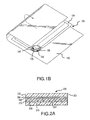
- Figure 1A is an isometric view of a food product packaged in a vented package of microwave interactive material.
- Figure 1B is an isometric view of the vented package of Figure 1A in the process of being surrounded by an insulating material.
- Figure 1C is an isometric view of the vented package of Figure 1A surrounded by an insulating material.
- Figure 2A is an exaggerated elevation, in cross-section, of an exemplary embodiment of the insulating microwave interactive packaging material of the present invention before the packaging is subjected to microwave energy in an operating microwave oven.
- Figure 2B is an isometric view, in cross-section, of the insulating microwave interactive packaging material of Figure 2A before the packaging is subjected to microwave energy in an operating microwave oven.
- Figure 2C is an isometric view, in cross-section, of the insulating microwave interactive packaging material of Figure 2A after the packaging material is subjected to microwave energy in an operating microwave oven.
- Figure 2D is an exaggerated elevation, in cross-section, of an alternative embodiment of the insulating microwave interactive packaging material of the present invention before the packaging is subjected to microwave energy in an operating microwave oven.
- Figure 3A is an isometric view of the bottom of a sheet of insulating microwave interactive packaging material with a hexagonal adhesive pattern according to a second embodiment of the present invention before the packaging is subjected to microwave energy in an operating microwave oven.
- Figure 3B is an isometric view of the top of the sheet of insulating microwave interactive packaging material with the hexagonal adhesive pattern of Figure 3A after the packaging is subjected to microwave energy in an operating microwave oven.
- Figure 4A is a plan view of an unassembled carton employing sheets of insulating microwave interactive packaging material according the present invention on the top and bottom interior surfaces of the carton.
- Figure 4B is a plan view of the unassembled carton of Figure 4A further showing slits cut in the sheets about the perimeter to augment contraction of the sheets in the X and Y dimensions during microwave heating.
- Figure 4C is an isometric view of the carton of Figure 4A assembled with a cutaway portion showing the sheet of insulating microwave interactive packaging material on the bottom interior surface of the carton.
- Figure 4D is an isometric view of the carton of Figure 4C with a cutaway portion showing the sheet of insulating microwave interactive packaging material on the both the top and bottom interior surfaces of the carton after microwave heating.
- Figure 5 is an isometric view of an envelope of insulating microwave interactive packaging material surrounding a food product according to a third embodiment of the present invention after the packaging is subjected to microwave energy in an operating microwave oven.
- Figure 6 is an elevation of two sheets of insulating microwave interactive packaging material fastened together at points along the perimeter of the sheets according to a fourth embodiment of the present invention after the packaging is subjected to microwave energy in an operating microwave oven.
- Figure 7A is a top plan view, in partial cross-section, of two sheets of insulating microwave interactive packaging material fastened together within an aperture in a baking disk with a hexagonal adhesive pattern according to a fifth embodiment of the present invention.
- the susceptor film and paper substrate of the upper sheet are partially cut away to reveal the adhesive pattern.
- the lower sheet is not visible.
- Figure 7B is a top plan view, in partial cross-section, of two sheets of insulating microwave interactive packaging material fastened together within an aperture in a baking disk with an adhesive pattern defining partial sectors of a circle according to a sixth embodiment of the present invention.
- the susceptor film and paper substrate of the upper sheet are partially cut away to reveal the adhesive pattern.
- the lower sheet is not visible.
- Figure 8 is an exaggerated elevation, in cross-section, of abuse-tolerant microwave packaging used in conjunction with the embodiments of Figures 7A and 7B .
- Figure 9A is an isometric view of a closed pouch of insulating microwave interactive packaging material according to another embodiment of the present invention.
- Figure 9B is a top plan view of the closed pouch of figure 9A .
- Figure 9C is a partial isometric view of the closed pouch of Figure 9A flipped top to bottom.
- Figure 10A is an exaggerated elevation, in cross-section, of another embodiment of the insulating microwave interactive packaging material of the present invention before the packaging material is subjected to microwave energy in an operating microwave oven.
- Figure 10B is an isometric view, in cross-section, of the embodiment of Figure 10A after the packaging material is subjected to microwave energy in an operating microwave oven.
- Figure 10C is an isometric view of a further embodiment of the insulating microwave interactive packaging material of the present invention after the packaging material is subjected to microwave energy in an operating microwave oven, wherein the packaging material of Figure 10A is formed into a container.
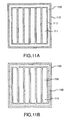
- Figure 11A is a plan view of a sheet of insulating microwave interactive material according to the present invention with elongate cells and indicating the adhesive bond line pattern.
- Figure 11B is plan view of a sheet of insulating microwave interactive material according to the present invention with elongate cells and indicating areas where the microwave interactive material is inactivated.
- Figure 12A is a plan view of a sheet of insulating microwave interactive material according to the present invention with elongate cells and indicating the adhesive bond line pattern.
- Figure 12B is a plan view of a sheet of insulating microwave interactive material according to the present invention with elongate cells and indicating areas where the microwave interactive material is inactivated.
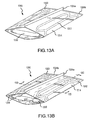
- Figure 13A is an isometric view of a cooking pouch constructed of a sheet of insulating microwave interactive material of Figures 12A and 12B .
- Figure 13B depicts the cooking pouch of Figure 13A after microwave heating.
- Figure 13C depicts the cooking pouch of Figure 13B in cross section as indicated in Figure 13B .
- the cross section is exaggerated to detail the various layers of the insulating microwave interactive material.
- Figure 13D depicts the cooking pouch of Figure 13B in cross section as indicated in Figure 13B .
- Figure 14A is an isometric view of a collapsible cooking package in its collapsed position holding the cooking pouch of Figure 13A without a food product.
- Figure 14B is an isometric view of the collapsible cooking package of Figure 14A in its functional position holding the cooking pouch of Figure 13A filled with a food product.
- Figure 15A is a plan view of a sheet of insulating microwave interactive material according to the present invention with triangular elongate cells and indicating the adhesive bond line pattern.
- Figure 15B is a plan view of a sheet of insulating microwave interactive material according to the present invention with triangular elongate cells and indicating areas where the microwave interactive material is inactivated.
- Figure 15C is an isometric view of a cooking pouch formed of two sheets of the insulating microwave interactive material of Figures 15a and 15B .
- Figure 15D is an elevation view of the open end of the cooking pouch of Figure 15C .
- Figure 16 is an isometric view, in cross-section, of a microwavable package according to the present invention designed to promote airflow through the package.
- Figure 17 is an elevation view of a microwavable package according to the present invention designed for ease of handling by a consumer.
- Figure 18 is an elevation view, in cross-section, of a microwavable package according to the present invention design for ease of handling by a consumer.
- Figure 19 is an elevation view of a microwavable package according to the present invention also designed for ease of handling by a consumer.
- Figure 20 is a top plan view, in cross-section, of another embodiment of a microwavable package according to the present invention with a corrugated susceptor.
- Figure 21 is a chart depicting the differences in temperature during a heating cycle inside a package alternately lined with a regular susceptor material and the insulating susceptor material of the present invention.
- This invention enhances the ability of microwave interactive packaging to improve microwave cooked food quality, when that quality relates to surface browning (i.e., the Maillard reaction), crisp texture, and internal moistness, through the insulation of the microwave interactive packaging.
- Certain types of microwave interactive material for example, susceptor material, utilizes microwave electromagnetic energy to generate package surface heat.
- the metallized, thin-film susceptor is a poor electrical conductor and generates heat like any resistance heater.
- the purpose of microwave susceptor packaging is to create surface heat to brown and crisp food product that it contacts during the microwave cooking process.
- Examples of typical microwave packages with susceptors include a paper pouch lined with a susceptor film and a paperboard sleeve lined with a susceptor film.
- Insulating material for surrounding these microwave packages may be provided by many materials. Examples include cloth, paper towels, non-woven substrates, corrugated paper and paperboard, quilted paper and towels, heat resistant multi-layer films formed with air pockets (e.g., bubble wrap and the insulating microwave packaging material disclosed herein), glass fiber, air cell foams, air cell gels, air cell rubber, cook-in cartons designed to retain heat, and any other material that can surround the susceptor and create a heat barrier.
- susceptor packaging either paper or paperboard construction
- raw dough or partially baked dough foods for example, pizza, filled pastry sandwiches and "finger” foods, waffles, crusted pies (fruit or meat), egg rolls, calzones, tacos, and pastry puffs
- "fried" foods for example, whole muscle and processed meats (e.g., fish and poultry) and other items like French fries, cheese, mushrooms, and vegetables.
- a food product 130 for example, a calzone
- the microwave interactive pouch package 100 may be a paper pouch 108 lined on the interior side with a susceptor film 105.
- the susceptor film 105 is placed adjacent to the food product 130 to promote browning and crisping of the pastry shell.
- the paper 108 provides a dimensionally stable substrate to support the susceptor film 105.
- the microwave interactive package 100 may also be designed to hold moisture so the food product 130 does not dry out and harden, especially on the edges.
- the edges 124 of the microwave interactive package 100 are sealed, for example, with a heat seal wherein the opposing sides of the interior of the pouch lined with susceptor film 105 are laminated around the edges 124.
- the food product 130 should not be cooked with the pouch 100 completely sealed because the pouch may inflate from water vapor released by the food product 130 during cooking, causing the susceptor film 105 to lose contact with the surface of the food product 130.
- a small vent opening 126 may be cut in the pouch 100, for example, in a corner, to allow some small "controlled" venting to occur.
- some moisture retention may be desirable to prevent the food product 130 from drying out during the cooking process. Therefore, a balance must be struck to prevent excessive vapor venting.
- an insulating material 140 is placed around the microwave interactive pouch 100 by, for example, folding the insulating material 140 as indicated by the arrows shown in Figures 1B and 1C .
- the insulating material 140 may be as simple as a paper towel.
- the insulating material 140 is folded over and around all sides of the pouch 100, including over the vent opening 126, to surround the microwave interactive packaging 100.
- the insulating material 140 may completely surround the packaging 100, or it may be selectively placed on or around portions of the packaging 100 to achieve any particular desired insulating effect.
- the insulating material 140 may further be moistened, for example, by dampening with water, to prevent excessive moisture loss and extend the cooking time available for the susceptor to brown and crisp the surface of the food product.
- the first pouch was then wrapped in a paper towel, similar to the depictions in Figure 1B and 1C , to provide insulation around the cooking pouch.
- the second pouch was not insulated and was placed in the microwave oven following the package instructions to place the food product directly into the microwave oven on a plate.
- Frozen calzones were cooked in the pouches for 2 minutes and 30 seconds. The calzones were then removed from the pouches and subjective measurements were recorded.
- the first calzone cooked in the pouch insulated by the paper towel resulted in a much crisper outer pastry surface and enhanced browning than the second calzone that was not insulated during cooking.
- the surface of the calzone cooked in the insulated pouch reflected light (i.e., was shiny) indicating a glazed crispness whereas the second calzone absorbed light indicating soft, soggy, porous surface.
- the first pizza was placed on a standard susceptor covered paper baking tray and was then wrapped in paper towels.
- the second pizza was also placed on a standard susceptor covered paper baking tray without the addition of insulating material.
- the crust on the bottom and edges of the first pizza cooked using insulation achieved greater browning and crisping than the second "control" pizza.
- a raw dough fruit pie was placed in a MicroFlex ® Q (Graphic Packaging Corporation, Golden, Colorado) microwave cooking pouch that completely surrounded the pie crust.
- a MicroFlex ® Q pouch is made of two paper-backed susceptor film sheets, wherein the edges of the sheets are sealed together to form a pouch.
- the susceptor film of one of the sheets is formed in a grid pattern, wherein the gridlines are devoid of metallization, in order to reduce browning effects of the susceptor film.
- the side of the pouch with the grid susceptor is usually placed on the top side of the pie to prevent an overdone top crust.
- the pouch with the pie was then placed in a plain paperboard pie tray for support. The tray and pie were then completely wrapped three times with a paper towel for insulation. The insulation wrapped pie was then placed in a microwave oven for cooking. The results of this experiment were very positive.
- the pie crust was crisp and golden after 16 minutes cooking time in a microwave oven.
- Test 1 Control.
- the chicken nuggets were placed on a paper plate in the microwave oven and cooked without benefit of a susceptor package or insulating covering.
- TEST 1 Cook Time (minutes) Starting Weight (oz) Cooked Weight (oz) Weight Loss (oz) Percent Weight Loss Internal Temperature (°F) 0.5 1.711 1.708 0.003 0.2% 78-143 1.0 1.708 1.547 0.161 9.4% 198-201 1.5 1.726 1.405 0.321 18.5% 180-192 1.5 1.794 1.468 0.326 18.2% 184-204 2.0 1.733 1.215 0.518 29.9% 201-207
- Test 2 MicroFlex ® Q pouch with multiple venting.
- the chicken nuggets were placed in a pouch made of NhcroFlex®Q material. Each side of the pouch was sealed, but each of the four corners of the pouch were cut off to provide vent openings.
- Test 3 MicroFlex ® Q pouch with single vent. Test 3 was performed similar to Test 2, but only one of the four corners of the pouch was cut for a vent opening. TEST 3 Cook Time (minutes) Starting Weight (oz) Cooked Weight (oz) Weight Loss (oz) Percent Weight Loss Internal Temperature (°F) 0.5 1.786 1.779 0.007 0.39% 30-165 1.0 1.802 1.677 0.125 6.9% 174-193 1.5 1.748 1.489 0.259 14.8% 179-199 1.5 1.774 1.552 0.222 12.5% 176-199 2.0 2.064 1.578 0.486 23.5% 178-200 2.0 1.771 1.337 0.434 24.5% 150-202 When cooking the chicken nuggets in a susceptor-lined pouch with only a small amount of venting, the moisture loss, and therefore the weight loss, of the nuggets during cooking was less than in either Test 1 or Test 2. The chicken in this instance was even more moist and tender on the inside, while still achieving a
- Test 4 MicroFlex ® Q pouch without venting. Test 4 used the same pouches as in Tests 2 and 3, but no vent openings were cut into the pouch. TEST 4 Cook Time (minutes) Starting Weight (oz) Cooked Weight (oz) Weight Loss (oz) Percent Weight Loss Internal Temperature (°F) 0.5 1.746 1.743 0.003 0.2% 23-107 1.0 1.771 1.721 0.050 2.8% 163-192 1.5 1.771 1.539 0.232 13.1% 180-202 1.5 1.727 1.508 0.219 12.7% 187-201 2.0 1.782 1.268 0.514 28.8% 168-204 Test 4 produced similar weight loss percentages to Test 3, but without the venting, the nuggets in Test 4 were not as brown and crisp on the surface.
- Test 5 Insulated MicroFlex ® Q pouch with single vent. In Test 5, one corner of the pouch was cut off for venting and the entire pouch was wrapped in three paper towel sheets for insulation and moisture retention. TEST 5 Cook Time (minutes) Starting Weight (oz) Cooked Weight (oz) Weight Loss (oz) Percent Weight Loss Internal Temperature (°F) 0.5 1.770 1.759 0.011 0.6% 25-104 1.0 1.763 1.666 0.097 5.50% 138-193 1.5 1.778 1.492 0.286 16.1% 175-196 2.0 1.762 1.334 0.428 24.3% 186-201 The moisture loss in Test 5, as shown by the percentage weight loss, was similar to the losses in Test 3 wherein another single vent pouch was used. As such, the chicken meat remained moist and tender. However, because of the addition of the insulating paper towel, the chicken nuggets of Test 5 attained greater browning and crisping levels than the nuggets of the previous tests.
- Test 6 Moist insulation around MicroFlex ® Q pouch with single vent. In Test 6, one corner of the pouch was cut off to provide a vent opening and the entire pouch was wrapped in three paper towel sheets moistened with water. TEST 6 Cook Time (minutes) Starting Weight (oz) Cooked Weight (oz) Weight Loss (oz) Percent Weight Loss Internal Temperature (°F) 1.5 1.772 1.666 0.106 6.0% 180-200 2.0 1.776 1.423 0.353 19.9% 184-200 2.5 1.776 1.275 0.501 28.0% 186-204 At 1.5 minutes, good crispness of the battered surface of the chicken nuggets was noted while the interior meat remained tender and moist.
- Test 7 Moist insulation around MicroFlex ® Q pouch without vent.
- Test 7 the same cooking configuration as Test 6 was used, with the exception that no vent opening was provided in the pouch.
- TEST 7 Cook Time (minutes) Starting Weight (oz) Cooked Weight (oz) Weight Loss (oz) Percent Weight Loss Internal Temperature (°F) 2.0 1.792 1.462 0.330 18.4% 180-199 2.5 1.784 1.241 0.543 30.4% 194-203 After 2 minutes of cooking, some areas of the chicken nuggets were crisp. All the nuggets appeared tender and moist on the inside.
- the pouch After 2.5 minutes of cooking, the pouch self-vented on one side, splitting at the seam to create a large opening (thus indicating the desirability for some level of venting).
- the chicken nuggets At the 2.5 minute mark, the chicken nuggets attained a good level of crispness, but were not as tender and moist as the nuggets of Test 6 wherein a small vent opening was provided in the pouch.
- written instructions may be provided on the microwave interactive packaging for a food product directing the consumer to wrap the package in a paper towel, a cloth towel, or some similar insulating material before cooking the food product in a microwave oven.
- the instructions could additionally direct the consumer to moisten the paper towel or other insulating material with water before wrapping it around the microwave interactive packaging. This instruction could further direct the consumer to cut a vent opening in the microwave interactive packaging before surrounding the packaging with the insulating material.
- a goal of product packaging is to provide the consumer with a product that is complete and easy to use.
- the food product can be cooked in the microwave oven in its original packaging to provide ease of use and time savings to the consumer.
- Product packaging should also not be bulky, but compact and uniform for ease of stacking and shipping. Low bulk packaging also reduces shipping and display costs because less space is required in trucks or other transport containers or for shelf display.
- FIG. 2A , 2B and 2C An insulating microwave packaging material 200 according to the present invention for use in consumer food product packaging is depicted in Figures 2A , 2B and 2C .
- the microwave packaging material 200 is the combination of several different material layers.
- a susceptor film 205 which may be the product of the deposition of a thin layer of microwave interactive material 204 on a first plastic film 202, is bonded, for example, by lamination with an adhesive 206 to a dimensionally stable substrate 208.
- the dimensionally stable substrate 208 is then bonded to a second plastic film 210.
- an additional substrate layer 230 may be adhered, for example with adhesive 232, to the first plastic film 202 opposite the microwave interactive material 204.
- This additional substrate layer 230 may be a layer of paper, which is provided to control the possible disintegration of the susceptor film 205 during heating.
- the susceptor film 205 may experience crazing under the extreme heat it generates and flakes of susceptor film 205 may peel away from the dimensionally stable substrate 208.
- the additional substrate 230 prevents any such flakes of the susceptor film 205 from falling into the food product.
- the bond between the dimensionally stable substrate 208 and the second plastic film 210 is in the form of a pattern, for example, a pattern of adhesive 212, that creates a plurality of closed cells 214. Resistance to vapor migration results as the closed cells 214 are bounded by the first plastic film 202, the adhesive 206, the adhesive pattern 212, and the second plastic film layer 210, each of which are resistant to vapor migration. To maximize the sealing of the cells, it may be desirable to achieve an adhesive bond directly between the susceptor 205 and the second plastic film 210, for example, by choosing an adhesive for the adhesive pattern 212 that may penetrate the dimensionally stable substrate 208 and contact the first adhesive layer 206 on the susceptor film 205.
- the microwave packaging material 200 presents as a substantially flat, multi-layered sheet as shown in Figure 2B . Such a flat configuration is desirable for use in packaging because it adds little bulk to the finished package.
- Figure 2C depicts, in cross-section, the microwave packaging material 200 of Figures 2A and 2B subjected to microwave energy in a microwave oven.
- the susceptor film 205 heats upon impingement by microwave energy, water vapor and other gases normally held in the paper substrate 208, and any air trapped in the thin space between the second plastic film 210 and the paper substrate 208 in the closed cells 214, expand due to the heat generated.
- the expansion of water vapor and air in the closed cells 214 applies pressure on the susceptor film 205 and the paper substrate 208 on one side, and the second plastic film 210 on the other side of the closed cells 214.
- each side of the microwave packaging material 200 forming the closed cells 214 reacts simultaneously to the heating and vapor expansion in a unique way.
- the cells 214 expand to form a quilted top surface 220 of pillows 216 separated by channels 218 in the susceptor film 205 and paper substrate 208 lamination, which lofts above a bottom surface 222 formed by the second plastic film 210.
- an originally compact packaging material is transformed into a bulk insulating material, without any further requirements for consumer preparation of the food product package before cooking. This effect occurs within 1 to 10 seconds in an energized microwave oven.
- the pillows 216 formed by expansion of the closed cells 214 in the microwave packaging material 200 provide significant insulation between the food product in the microwave packaging material 200 and the interior surfaces of the microwave oven.
- the base of a microwave oven for example, the glass tray found in most microwave ovens, acts as a large heat sink, absorbing much of the heat generated by the susceptor film 205 or within the food product itself.
- the vapor pockets in the pillows 216 formed by the present invention may be used to insulate the food product and susceptor film 205 from the microwave oven surfaces and the vented air in the microwave oven cavity, thereby increasing the amount of heat that stays within or is transferred to the food product.
- the formation of the pillows 216 creates an ability for the microwave packaging material to more closely conform to the food product, placing the susceptor film 205 in closer contact with the food product. This close contact enhances the ability of the susceptor film 205 to brown and crisp the surfaces of the food product by conduction heating in addition to some convection heating of the food product.
- a biaxially-oriented polyester substrate for example, 48-gauge polyester film web
- a microwave interactive material 204 for example, aluminum
- any suitable lossy substance that will convert microwave radiation into heat energy in a microwave oven can be used as the microwave interactive material 204.
- Such substances fall primarily into four groups: conductors, semi-conductors, ferromagnetic materials, and dielectic materials.
- microwave interactive materials used in the present invention to form microwave interactive layer 204 are compositions containing metals or other materials such as aluminum, iron, nickel, copper, silver, carbon, stainless steel, nichrome, magnetite, zinc, tin, iron, tungsten and titanium. These materials may be used in a powder, flake or fine particle form.
- the polyester-aluminum combination alone is referred to herein as a "susceptor film.”
- Other types of biaxially-oriented, plastic film 202 may also be substituted for the polyester film.
- aluminum When aluminum is used to create the microwave interactive layer of a susceptor film 205, it may be applied to the polyester substrate, for example, by sputter or vacuum deposition processes, to a thickness of between 50 ⁇ and 2,000 ⁇ .
- Exemplary embodiments of susceptors that may be used in the context of this invention include MicroFlex ® Q, MicroRite ® (Graphic Packaging Corporation, Golden, Colorado), and the susceptors described in U.S. Patent Nos. 4,641,005 ; 4,825,025 ; 6,133,560 ; and 6,414,290 .
- the areas of the microwave interactive material layer 204 directly corresponding to the adhesive pattern 212 to be applied may be inactivated.
- U.S. Patent Nos. 4,865,921 ; 4,883,936 ; and RE34,683 each of which is hereby incorporated herein in its entirety, describe various processes for selective and patterned inactivation of microwave interactive materials. Inactivating the microwave interactive material layer 204 opposite the adhesive pattern 212, provides several benefits. The adhesive pattern 212 is more likely to maintain a strong bond between the dimensionally stable substrate 208 and the second plastic film 210 because the extreme heat generated by the microwave interactive material layer 204 is not acting directly on the adhesive and potentially weakening its constitution.
- a stronger adhesive bond results in a better vapor barrier forming the cells 214 and better pillowing effects upon heating. Greater options for possible adhesives are also available because the temperature requirements for maintaining adherence are reduced. Further, because the microwave interactive material layer 204 is removed from the perimeters of the cells 214, upon the contraction of the second plastic film layer 210 and the formation of the pillows 218, ribs that are cool to the touch of a user may be formed opposite the channels 218. These cool to the touch patterned surfaces allow a user to comfortably hold the food product in the packaging while the food product and the packaging are still quite hot from the microwave cooking process. This embodiment is described in greater detail herein with respect to Figures 11A-13D .
- chelating agents are ethylenediaminetetracetic acid (EDTA), diethylenetriaminepentacetic acid (DTPA) and hydroxyethylenediaminetriacetic acid (HOEDTA).
- EDTA ethylenediaminetetracetic acid
- DTPA diethylenetriaminepentacetic acid
- HOEDTA hydroxyethylenediaminetriacetic acid
- Solutions of Zr +4 useful in the present invention may include ammonium zirconium carbonate, sodium zirconium lactate, ammonium zirconium lactate, and zirconium tartrate.
- amines and hydroxyamines useful in the present invention include ethanolamines, choline and salts thereof.
- Acids useful in the present invention include acetic, formic and other organic acids as well as dilute mineral acids such as hydrochloric acid, hydrofluoric acid and mixtures thereof.
- dilute bases useful in the present invention include potassium hydroxide, sodium hydroxide, lithium hydroxide, sodium and potassium carbonates, and sodium and potassium phosphates.
- salt solutions of salts such as ferric chloride, sodium citrate, sodium tartrate, ferric sulphate, ferrous chloride, ferrous ammonium sulphate, ammonium fluoride, sodium fluoride, zinc chloride, zinc oxide and zinc fluoride are examples of salt solutions useful in the present invention.
- Sodium hydroxide is the preferred material used to treat microwave interactive layer 204 in accordance with the present invention, particularly when aluminum metal is the microwave interactive material making up the microwave interactive layer 204.
- the pH of solutions of sodium hydroxide used to inactivate portions of the microwave interactive layer 204 preferably ranges from about 7.5 to about 13 and is more preferably maintained in the range of about 8.5 to about 11.
- the sodium hydroxide solution used to treat an aluminum microwave interactive layer is at room temperature although the temperature may be higher or lower than normal room temperature.
- surfactant it is generally also advantageous to add a small amount of surfactant to solutions of an inactivating chemical used to treat the microwave interactive layer to improve the wetting characteristics of the chemical and the subsequent reaction of the chemical with the microwave interactive layer.
- surfactants which may be used include CERFAK 1400TM produced by E. F. Houghton, KATAMUL-1GTM produced by Scher Chemicals, Inc., IGEPAL-C0630TM produced by GAP Corporation and TRITON X-100TM produced by Rohm & Haas.
- a surfactant preferred for use in conjunction with sodium hydroxide is TRITON X-100TM.
- the completed susceptor film 205 layer is next coated with an adhesive 206, for example, a wet-bond adhesive, preferably on the aluminum deposition layer, rather than the side with the exposed polyester, for creating a laminate with at least one other substrate layer. Bonding the additional substrate to the aluminum deposition allows the polyester to act as a protective layer over the microwave interactive aluminum 204, rather than exposing the aluminum side in the finished product.
- This lamination step adheres the susceptor film 205 to a dimensionally-stable, packaging substrate 208, for example, paper, paperboard, or a plastic substrate. If the chosen substrate is paper or paperboard, a wet bond adhesive is preferably used; if the substrate is a plastic, a dry bond adhesive is preferred.
- Typical types of paper substrates that may be used with this invention range between 10 1b and 100 1b paper, for example, 25 1b paper. Typical ranges for paperboard substrates that may be used with the present invention include 8-point to 50-point paperboard.
- plastic substrates of between 0.5 mils and 100 mils thickness are also applicable.
- Appropriate plastic substrates are polymers that respond in a similar manner to the paper substrates.
- the plastic substrate should be easily pliable to distort and move with the susceptor film 205 as it heats and bulges.
- a plastic substrate should have a higher softening point than the plastic used to create the susceptor film 205.
- the plastic substrate when used to support a susceptor film 205 with an aluminum deposition as the microwave interactive layer 204, the plastic substrate should be able to withstand temperatures in the range of 350° F to 425° F without melting, burning, or otherwise disintegrating.
- dimensionally-stable when describing a substrate 208 refers to the interface of the substrate 208 and the susceptor film 205. Dimensionally-stable indicates a substrate 208 that will not soften, melt, or flow when subjected to the heat generated by the microwave interactive material 204. However, “dimensionally stable” does not mean that a substrate 208 is not malleable or may not be deformed from an original shape or configuration. The purpose of a dimensionally stable substrate 208 is to prevent the susceptor film 205 from disintegrating (e.g., by the melting of the plastic film 202) upon heating.
- a second lamination step completes the manufacturing process.
- a further layer of adhesive 212 is applied to the substrate 208 in a pattern.
- a second layer of polyester film 210 is then adhered to the substrate 208.
- the adhesive pattern 212 renders a nested array of closed cells, wherein the perimeters of adjacent cells are shared borders.
- the adhesive 212 may be chosen to penetrate the paper substrate 208 and contact the first adhesive layer 206, thereby creating cells 214 bounded by the adhesive pattern 212, the first adhesive layer 206 and the adjacent susceptor film 205, and the second polyester film 210.
- the cells 214 thus created, which each encapsulates a portion of the paper substrate 208, are substantially vapor-impermeable and air-tight, thereby holding in the expanding water vapor and air during heating.
- each cell 214 is generally minimal as most of the air is evacuated when the second polyester film 210 is pressed against the paper substrate 208 in the lamination process.
- the amount of moisture trapped in the paper substrate 208 and the cells 214 will influence the amount of cell expansion upon heating. If merely the paper substrate 208 were one of the boundaries of the cells 214, much of the water vapor and air would escape through the porous bulk of the paper substrate 208, and the formation of pillows 216 in the microwave packaging material 200 would be much less pronounced.
- the microwave packaging material 200 undergoes a transformation.
- the microwave interactive layer 204 heats due to the microwave energy, the first plastic film 202 supporting the microwave interactive layer 204 becomes extremely hot, between 350° F and 425° F. At such a high temperature, the first plastic film 202 softens and would flow were it not supported by the substrate 208.
- This vapor expansion creates pressure in the closed cells 214, and the susceptor side of the cells 214 bulges outward under the pressure. Because the plastic film 202 is softened by the heat, it is able to stretch and distort with the substrate 208 under pressure.
- the second plastic film 210 is heated, but not to the same degree as the first plastic film 202 because the substrate 208 and the expanding air and water vapor insulate the second plastic layer 210 from the intense heat of the microwave interactive layer 204. Although softened by the heat, the second plastic layer 210 is not hot enough to flow and it either remains stable or, as in some embodiments described herein, actually contracts in surface area as a result of the biaxial orientation, wherein the polymer chains attempt to contract to their original state.
- each pillow 216 are channels 218 where the patterned adhesive 212 holds the susceptor film 205, the substrate 208, and the second plastic film 210 together.
- the second layer of polyester film 210 is preferably biaxially-oriented polyester as is the first layer of polyester film 202.
- Biaxial orientation means the polyester film has been stretched in both the X and Y directions during its manufacture resulting in uniformly aligned polymer chains of molecules in the polyester film. The alignment of polymer chains creates additional strength in the polyester sheet, even as it is stretched thinner. This increased strength is important to the creation of the susceptor film 205, as the first polyester film 202 is better able to support the deposition of the aluminum microwave interactive layer 204. The increased strength of both the first and second polyester films 202, 210 also makes them easy to work with during the manufacture of the microwave packaging material 200.
- the alignment of the polymer chains further increases the resistance of the polyester films 202, 210 to heat.
- the first polyester film 202 is subjected to very high temperatures when the microwave interactive layer 204 heats upon impingement by microwave energy.
- the biaxial orientation of the polyester film 202 helps maintain the integrity of the susceptor film 205 by raising the heat distortion temperature of the polyester film 202.
- the biaxially-oriented polyester film 202 attempts to contract in the X-Y direction as the polymer chains attempt to return to their original form.
- the polyester film 202 is unable to contract.
- the polyester film 202 does soften, however, allowing it and the paper substrate 208 to yield and pillow-up under the pressure of the expanding water vapor and air. Once formed into the pillow shape, the paper substrate 208 is resistant to returning to its original flat form.
- the heat resistant properties of the biaxial orientation of the second polyester film 210 result in a different effect for the second polyester film 210.
- the second polyester film 210 is separated from the microwave interactive film 204 by the paper substrate 208, which also provides insulation from the heat generated by the susceptor film 205. Therefore, the second polyester film 210 does not heat to the same degree as the first polyester film 202. Further, as the air and water vapor in each cell 214 expand, the second polyester film 210 is further insulated from the heat generated. The heat transferred to the second polyester layer 210 is not as great as the heat transferred to the first polyester film 202.
- the heat transferred to the second polyester film 210 is enough to cause the polymer chains to contract in both the X and Y directions, regressing toward the form of the polyester film 210 before it was stretched to produce the biaxial orientation.
- This contraction creates a taught bottom surface 222 of the microwave packaging material 200, which is more resistant to the pressure of the expanding water vapor, and enhances the pillowing effect on the top surface 220 of the microwave packaging material in the Z direction.
- the amount of Z-direction expansion also greatly depends upon particular microwave oven conditions and various food load factors, for example, size, weight, and temperature. All of these factors combine to create a load factor that may not always be exceeded by the expansion factor of the microwave packaging material to achieve the maximum benefit of the invention.
- Figures 3A and 3B show an exemplary embodiment of many possible adhesive patterns 312 for creating the cells 314 within the packaging material 300.
- a hexagonal adhesive pattern 312, as shown in Figures 3A and 3B is an excellent basic polygonal pattern to select due to its ability to nest perfectly with adjacent hexagons and its high degree of cylindrical symmetry.
- Other shapes for use as adhesive patterns 312, for example, circles, ovals, and other curvilinear shapes, preferably symmetrical curvilinear shapes, for example, multi-lobed flower shapes, triangles, squares, rectangles (a shown in Figures 2A and 2B ), and other polygonal shapes, preferably right polygons, and even more preferably equilateral polygons, are within the scope of the present invention.
- symmetrical curvilinear shape means a closed curvilinear shape that can be divided in half such that the two halves are symmetrical about an axis dividing them.
- right polygon means a polygon that can be divided in half such that the two halves are symmetrical about an axis dividing them. Equilateral polygons would therefore be a subset of right polygons.
- These adhesive patterns 312 are preferably configured in arrays such that they are similarly capable of tiling or nesting as depicted in Figure 3A by the adhesive pattern 312 showing through the second plastic film 310 on the bottom surface 322 of the packaging material 300. When heated by microwave energy, the top surface 320 of the microwave packaging material 300 expands and forms the pillows 316 and channels 318.
- the arrays of adhesive patterns 312 need not be repetitive of a single shape, but instead can be combinations of various shapes, preferably capable of nesting or tiling together to share common perimeters.
- an array of shapes for an adhesive pattern 312 might be an array of nested hexagons and polygons, as in the patchwork of a soccer ball.
- FIGS 4A, 4B , 4C, and 4D depict an exemplary embodiment of a microwave food package 410 that employs two sheets 400a, 400b of the insulating microwave packaging material of the present invention.
- the microwave food package 410 may be a paperboard carton 402, shown as a blank in Figures 4A and 4B and shown assembled in Figures 4C and 4D .
- the carton 402 may be formed of a bottom panel 404a, a top panel 404b, side panels 406a, 406b, 406c, 406d, a bottom flap 408a, a top flap 408b, corner tabs 422a, 422b, 422c, 422d, and a back panel 426.
- a bottom tray of the carton 402 for holding a food item to be cooked is formed out of the bottom panel 404a, the bottom flap 408a, the back panel 426, and the side panels 406a, 406b.
- the side panels 406a and 406b are folded upward along score lines 430a and 430b, respectively.
- the bottom flap 408a is folded upward along score line 428a and the back panel is folded upward along score line 428b.
- the bottom flap 408a is secured to the side panels 406a and 406b by folding tabs 422a and 422b along score lines 438a and 438b, respectively, and then inserting tabs 422a and 422b into slots 424a and 424b, respectively.
- the back panel 426 is secured to the side panels 406a and 406b by folding tabs 422c and 422d along score lines 438c and 438d, respectively, and then inserting tabs 422c and 422d into slots 424c and 424d, respectively.
- a lid for the carton is formed out of the top panel 404b, the side panels 406c, 406d, and the top flap 408b.
- the top panel 404b is folded along score line 428c to rest on the side panels 406a and 406b and the bottom flap 408a.
- the side panels 406c and 406d are folded downward along perforation lines 432a and 432b, respectively, to rest flat against side panels 406a and 406b, respectively.
- the top flap 408b may be folded downward along score line 428d to rest flat against bottom flap 408a.
- top flap 408b and the side panels 406c and 406d may be secured to bottom flap 408a and side panels 406a and 406b, respectively, for example, with adhesive in order to secure the lid to the tray and hold the food item inside until the carton 402 is opened by the user after cooking.
- the carton 402 may be easily opened by the user by pulling upward on the top flap 408b.
- the top flap 408b and the top panel 404b will rip open along perforation lines 432a and 432b allowing the user easy access to the food item while maintaining the integrity of the tray to hold the food item. Cutouts 434a and 434b may be formed in top flap 408b to aid in the initial tearing along perforation lines 432a and 432b, respectively.
- the cells 414 of the sheets 400a, 400b are formed as squares by the adhesive pattern 412.
- the sheets 400a, 400b may be affixed to the bottom panel 404a and top panel 404b of the carton 402 with adhesive tacks 436.
- the adhesive tacks 436 may be placed at the corners of the sheets 400a, 400b to allow for some movement of the sheets 400a, 400b as the polyester layer of the insulating microwave packaging material shrinks during heating.
- centered slits 440a or off-centered slits 440b be may be cut in the sheets 400a, 400 in close proximity to the perimeters between the adhesive tacks 436 to allow for even greater movement of the sheets 400a, 400b as the polyester layer of the insulating microwave packaging material shrinks during heating.
- the location and arrangement of slits 440a and 440b and adhesive tacks 436 are exemplary and many other slit patterns and glue patterns may be used to allow for Z-directional expansion and X-Y directional contraction of sheets 400a and 400b.
- the adhesive used for the tacks 436 may also be heat sensitive and release as the sheets 400a, 400b heat under the excitation of microwave energy.
- the sheets 400a, 400b are able to contract as necessary during heating and allow the cells 414 to expand to form the pillows 416.
- the sheets remain generally in place as they are constrained by the side panels 406a and 406b, the bottom flap 408a, and the back panel 426, as well as the food item resting on the bottom sheet 400a.
- the formation of the pillows 416 by the sheets 400a, 400b of the insulating microwave packaging material of the carton 402 provides several advantages over cartons using flat susceptor sheets or coatings on the interior panels of such cartons.
- the susceptor material pillows 416 to become closer in proximity to the food item, especially to the top surface of the food item as the sheet 402b on the top panel forms pillows 416. This provides for increased surface heating, browning, and crisping of the top of the food item.
- the air and water vapor in the pillows 416 provides added insulation, trapping heat in the carton 402 and enhancing the cooking result of the food item.
- a carton with quilted susceptor sheets of the type shown in Figures 4C and 4D was used to cook French fries in a microwave oven.
- a sheet of microwave packaging material 500 according to the present invention is folded over on itself with the top surface 520 facing inward and the bottom surface 522 composed of the second plastic film 510 facing outward.
- the two edges of the sheet of microwave packaging material 500 opposing the fold line 526 are fastened together, for example, via heat sealing or adhesive, to form a sealed edge 524.
- the sheet of packaging material 500 is thereby transformed into an envelope or sleeve into which a food product 530, for example, a fruit pie snack, may be placed.
- a food product may rest on the base of a microwave package incorporating susceptor material, for example, a cooking sleeve, but the food product may not touch or be in close proximity with the sides or top of the package. While the bottom of the food product may become brown and crisp because of the contact between the packaging and the food product, the sides and top of the food product will have less browning and crisping because of lack of contact with the susceptor material.
- the microwave packaging material 500 expands to form the pillows 516 on the top surface 520, which bring the susceptor film 505 in close proximity to or contact with the food product 530 on all sides, providing the desired cooking effect on all sides of the food product 530.
- the channels 518 between the pillows 516 in the quilted top surface 520 provide the added benefit of venting water vapor released from the food product 530 during cooking, which further enhances the surface browning and crisping effects of the susceptor film 505.
- the vapor filled cells 514 further insulate the food product 530 from the microwave oven and ensure the heat generated remains in the food product 530 rather than transferring to the oven environment.
- the size and shape of a food product may vary and/or shrink during cooking and pull away from a susceptor positioned adjacent the food product.
- the insulating microwave packaging material 500 may fill the void created by the shrinking food product with the expansion of the pillows 516 on the top surface 520, maintaining the susceptor film 505 in constant contact with or close proximity to most surfaces of the food product 530.
- Some food products, for example, bread dough, have the opposite tendency while cooking and actually rise or expand.
- the microwave packaging material 500 is also beneficial for use with such rising food products 530.
- the microwave packaging material 500 initially expands to meet the food product 530 before the food product 530 has risen.
- the microwave packaging material 500 has some give to yield to the rising food product 530 as the pressure within the cells 514 from the heated water vapor is not so high as to fully resist such external pressure.
- the vapor expansion in each of the plurality of closed cells 514 and the simultaneous contraction of the second plastic layer 510 increases the thickness of the packaging material 500 by at least an order of magnitude.
- a novel benefit of the microwave packaging material 200 of the present invention is its ability to insulate against heat transfer from the food product or the microwave packaging material 200 itself to the microwave oven environment during cooking.
- the vented air in the oven cavity and the glass tray, or other cooking platform act as large heat sinks, absorbing much of the heat generated by either the microwave heating of the food product or the microwave interactive materials, for example, susceptor materials, thereby lessening the ability of the microwave packaging material to augment the heating and browning of the food product.
- the vapor and gases from the paper substrate 208 expand into the closed cells 214, as shown in Figure 2C .
- These vapor pockets formed in the closed cells 214 transform the microwave packaging material 200 into an insulator that reduces heat transfer between the microwave packaging material 200 and the microwave oven environment. These insulation qualities result in improved performance of the heating properties of the susceptor film 205.
- a first sheet 600a and a second sheet 600b of the microwave packaging material are placed bottom side 622a to bottom side 622b, the second plastic film 610a of the first sheet 600a facing the second plastic film 610b of the second sheet 600b.
- the sheets 600a, 600b may be tacked together, for example, by adhesive or heat seal, at several points 628 spaced apart from each other along the perimeters of sheets 600a, 600b.
- the corners of the sheets 600a, 600b may be tacked together; if the sheets are round, several points spaced apart along the perimeter of the sheets may be chosen and the sheets tacked together at those points.
- a frozen food product placed upon a microwave oven surface will cool the microwave oven surface before the microwave oven is energized, increasing the amount of heat transfer to the microwave oven surface once the cooking process begins.
- the susceptor film 605b heats the microwave oven surface while the susceptor film 605a of the opposite sheet 600a heats the food product, further reducing the ability of the microwave oven surface to act as a heat sink.
- the bottom sheet 600b of the dual sheet embodiment creates enough heat energy immediately to cause the vapor expansion in the cells 614a, 614b of both sheets of the microwave packaging material 600a, 600b soon after the microwave oven is energized. If there were only one sheet of microwave packaging material, for example 600a, the frozen food product would significantly increase the time required to heat the water vapor and air and achieve expansion of the cells 614a because the surface temperature of the susceptor film 605a will not rise until the surface temperature of the food product accordingly rises.
- the opposing sheets of packaging material 600a, 600b are only attached at points 628 at their perimeters on the corners to allow for movement of the sheets 600a, 600b in the X and Y directions.
- the back-to-back sheets 600a, 600b are exposed to microwave energy in a microwave oven, the cells 614a, 614b expand in the Z direction, and the second plastic film layers 610a, 610b contract in both the X and Y directions as a result of the biaxial orientation of the plastic film 610a, 610b as discussed above. Therefore, some freedom of movement in the X-Y directions is desirable in order to achieve favorable expansion results.
- microwave packaging material 600a, 600b may be desirable, however, to provide some external structure to the microwave packaging material 600a, 600b, such as attachment points on the perimeters, to augment uniform shrinkage in both the X and Y directions and minimize distortion or wrinkling of the microwave packaging material 600a, 600b in any particular direction.
- some external structure to the microwave packaging material 600a, 600b, such as attachment points on the perimeters, to augment uniform shrinkage in both the X and Y directions and minimize distortion or wrinkling of the microwave packaging material 600a, 600b in any particular direction.
- the elevation achieved by individual cells after microwave heating was between 0.375 in and 0.5 in from a starting thickness of the insulating microwave packaging material of less than 0.03125 in.
- the opposing sheets 600a, 600b also deform on a macro scale from their original flat, paper-like form.
- the first sheet 600a deforms into a convex canopy with respect to a plane dividing the first and second sheets 600a, 600b.
- the second sheet 600b deforms into a convex canopy with respect to the plane dividing the first and second sheets 600a, 600b.
- an air space is created between the sheets 600a, 600b providing greater than double the insulation of a single sheet, isolating the food product from the potential heat sink of the microwave oven surface.
- FIG. 7A A particular packaging configuration using the principles of the embodiment of Figure 6 is shown in Figure 7A .
- An aperture 745 may be made in the center of the abuse-tolerant baking disk 740, within which a circular piece of the dual sheet embodiment (as described with reference to Figure 6 herein) of the packaging material 700 is placed.
- the sheets of packaging material 700 may be attached to each other, for example, at areas 728, allowing the perimeter edges of the sheets of packaging material 700 to sandwich a small width of the perimeter of the abuse-tolerant baking disk 740 defining the aperture 745 between each sheet, thus holding the packaging material 700 within the aperture 745 in the abuse-tolerant baking disk 740.
- each sheet of the packaging material 700 may be fastened, for example with a heat sensitive adhesive, to respective opposing sides of the baking disk 740 along portions of the aperture 745.
- a heat sensitive adhesive may break down allowing the second plastic film 710 of the packaging material 700 the necessary range of X-Y dimensional movement to optimize the expansion effect in the cells.
- the microwave packaging material 700 When heated by the impingement of microwave energy, the microwave packaging material 700 expands, insulating the pizza from the heat sink of the microwave oven surface and pushing the susceptor material into close contact with the raised center of the frozen pizza, thereby providing increased heating, browning, and crisping to the center of the pizza.
- the benefit of the dual sheet embodiment of the microwave packaging material 700 in creating immediate expansion of the cells when used with a frozen food product as described previously is readily apparent in the frozen pizza situation.
- the susceptor film 705 against the microwave oven surface also heats that surface, thereby additionally counteracting its effects as a heat sink and allowing heat generated by the susceptor film 705 against the pizza center to transfer only to the pizza.
- the cell areas 716 of the insulating new package material 700 are defined by an adhesive pattern 712 subdividing partial sectors of a circle (rather than the hexagonal pattern in Figure 6 ) to capitalize on the circular configuration of the microwave packaging material 700 within the aperture 745 in the abuse-tolerant baking disk 740.
- Each sheet of the microwave packaging material 700 is fastened as previously described to either the opposing sheet or the abuse-tolerant baking disk 740 at various areas 728, with the susceptor film 705 sides facing outward, to aid in maintaining the perimeter shape of the microwave packaging material 700 during heating, while allowing for X-Y dimensional contraction of the second plastic film 710.
- a cross-section of abuse-tolerant microwave packaging material 800 used for the baking disks of Figures 7A and 7B is shown in Figure 8 .
- the abuse-tolerant packaging material 800 of this exemplary embodiment is formed of a polyester substrate 802 covered by a thin deposition of aluminum 804 to create a susceptor film 805.
- a dimensionally stable substrate e.g., paperboard
- the polyester substrate 802 and aluminum layer 804 function as a susceptor.
- the aluminum layer 804 is covered with a dry bond adhesive layer 806.
- An aluminum foil layer 808 is adhered to the susceptor film 805 via the dry bond adhesive layer 806.
- a patterned ink resist coat 810 is printed on the foil layer 808, and the exposed foil layer 808 is etched away in a caustic bath.
- the patterned foil layer 808 and ink resist coat 810 are covered by a second adhesive layer 812.
- the adhesive layer 812 is a wet bond adhesive.
- the adhesive layer 812 further covers the etched areas between the patterned foil elements 808 and adheres in these areas to the dry bond adhesive layer 806.
- the final component of this exemplary embodiment is a dimensionally stable paperboard substrate 814 that is adhered to the previous layers by the second adhesive layer 812.
- the abuse-tolerant microwave packaging material 800 forming the pizza baking disk redistributes incident microwave energy by increasing the reflection of microwave energy while maintaining high microwave energy absorption.
- a repeated pattern of metallic foil segments 808 can shield microwave energy almost as effectively as a continuous bulk foil material while still absorbing and focusing microwave energy on an adjacent food surface.
- the metallic segments 808 can be made of foil or high optical density evaporated materials deposited on a substrate 802.
- High optical density materials include evaporated metallic films that have an optical density greater than one (optical density being derived from the negative logarithm of the ratio of transmitted light to incident light).
- High optical density materials generally have a shiny appearance, whereas thinner metallic materials, such as susceptor films 805 have a flat, opaque appearance.
- the metallic segments 808 are foil segments.
- the metallic segments 808 may form segmented outlines of various shapes. Such shapes may be, for example, circles, ovals, and other curvilinear shapes, preferably symmetrical curvilinear shapes, for example, multi-lobed flower shapes, triangles, squares, rectangles, and other polygonal shapes, preferably right polygons, and even more preferably equilateral polygons, are within the scope of patterns of the abuse-tolerant packaging material 800.
- the hexagon is an excellent basic polygon to select due to its ability to nest perfectly along with its high degree of cylindrical symmetry.
- the shapes formed by the microwave reflective segments 808 are preferably configured in arrays such that they are similarly capable of tiling or nesting.
- arrays of shapes need not be repetitive of a single shape, but instead can be combinations of various shapes, preferably capable of nesting or tiling together with small gaps between the metallic segments 808.
- an array of shapes might be an array of nested hexagons and polygons, as in the patchwork of a soccer ball.
- the segmented foil 808 (or high optical density material) structure prevents large induced currents from building at the edges of the abuse-tolerant packaging material 800 or around tears or cuts in the abuse-tolerant packaging material 800, thus diminishing the occurrences of arcing, charring, or fires caused by large induced currents and voltages.
- the abuse-tolerant design includes a repeated pattern of small metallic segments 808, wherein each segment acts as a heating element when under the influence of microwave energy. In the absence of a dielectric load (i.e., food), this energy generates only a small induced current in each element and hence a very low electric field strength close to its surface.
- the power reflection of the abuse-tolerant packaging material 800 is increased by combining the abuse-tolerant packaging material 800 with the susceptor film layer 805.
- a high surface-heating environment is created through the additional excitement of the susceptor film 805 due to the composite action of food contacting the small metallic segments 808.
- the quasi-resonant characteristic of perimeters defined by the metallic segments 808 can stimulate stronger and more uniform cooking.
- the present invention can stimulate uniform heating between the edge and center portion of a sheet of the abuse-tolerant metallic segments 808 combined with a susceptor film 805 to achieve a more uniform heating effect.
- the average width and perimeter of the pattern of metallic segments 808 will determine the effective heating strength of the pattern and the degree of abuse-tolerance of the pattern.
- the power transmittance directly toward the food load through the abuse-tolerant metallic segments 808 is dramatically decreased, which leads to a quasi-shielding functionality.
- the array effect of the small metallic segments 808 still maintains a generally transparent characteristic with respect to microwave power energy. Thus, the chances of arcing or burning when the material is unloaded or improperly loaded are diminished.
- each of the metallic segments 808 has an area less than 5 mm 2 and the gap between each of the small metallic segments 808 is larger than 1 mm.
- Metallic segments 808 of such size and arrangement reduce the threat of arcing that exists under no-load conditions in average microwave ovens.
- the capacitance between adjacent metallic segments 808 will be raised as each of these substances has a dielectric constant much larger than a typical substrate on which the small metal segments 808 are located. Of these materials, food has the highest dielectric constant (often by an order of magnitude).
- each set of metallic segments 808 is preferably a predetermined fraction of the effective wavelength of microwaves in an operating microwave oven.
- the predetermined fraction is selected based on the properties of the food to be cooked, including the dielectric constant of the food and the amount of bulk heating desired for the intended food.
- a perimeter of a set of metallic segments 808 can be selected to be equal to predetermined fractions or multiples of the effective microwave wavelength for a particular food product.
- a resonant fraction or multiple of the microwave wavelength is selected when the abuse-tolerant microwave packaging material 800 is to be used to cook a food requiring strong heating, and a smaller, high-density, nested perimeter of a quasi-resonant, fractional wavelength is selected when the abuse-tolerant microwave packaging material 800 is used to cook food requiring less heating, but more shielding. Therefore, the benefit of concentric but slightly dissimilar perimeters is to provide good overall cooking performance across a greater range of food properties (e.g., from frozen to thawed food products).
- FIG. 9A, 9B , and 9C is a combination of the structures of the embodiments of Figures 4 and 5 . It has been found that when the insulating microwave packaging material is made in the form of a bag or pouch, the cells generally expand more uniformly.
- a sealed pouch 900 is formed by bringing two opposing edges of a first sheet of insulating microwave packaging material 940 together with the top surface 920 ( Figure 9C ) composed of the susceptor layer facing inward and the bottom surface 922 composed of the second plastic film facing outward.
- the two opposing edges of the first sheet of packaging material 940 are fastened together, for example, via heat sealing or adhesive, to form a sealed edge 924a.
- the first sheet of packaging material 940 is thereby transformed into an envelope or sleeve into which a food product 930 may be placed.
- the first sheet 940 could be wrapped around the food product 930 with the food product 930 in situ.
- the opposing edges of the first sheet 940 at each open end of the sleeve are also fastened together, again for example, via heat sealing or adhesive, to form sealed edges 924b and 924c, respectively, forming a completely sealed pouch 900.
- the corners of the sealed pouch 900 are then cut off to provide vent holes 926a, 926b, 926c, and 926d that allow steam from the food product 930 to escape.
- a second sheet of insulating microwave packaging material 950 is attached to the bottom side 952 of the pouch 900, i.e., the side of the pouch 900 that will rest on the floor or turntable of a microwave oven during cooking.
- the second plastic film side of the second sheet 950 faces the second plastic film side of the first sheet 940.
- the second sheet 950 may be tacked to the first sheet 940, for example, by adhesive or heat seal, at several points 956 spaced apart from each other along the perimeter of the second sheet 950. For example, if the second sheet 950 is square or rectangular, the corners of the second sheet 950 may be tacked to the outer surface of the first sheet 940.
- the second sheet of packaging material 950 is only attached at points 956 at the corners to allow for movement of the second sheet 950 in the X and Y directions.
- the pouch 900 expands to form the pillows on the top surface 920, which bring the susceptor film in close proximity to or contact with the food product 930 on all sides, providing the desired cooking effect on all sides of the food product 930.
- the channels between the pillows in the quilted top surface 920 provide the added benefit of venting water vapor released from the food product 930 to the vent holes 926a, 926b, 926c, 926d during cooking, which further enhances the surface browning and crisping effects of the susceptor film.
- the vapor filled cells of the first sheet 940 also further insulate the food product 930 from the microwave oven environment and ensure the heat generated remains in the food product 930 rather than transferring to the oven environment.
- the second sheet 950 of microwave packaging material intercedes between the first sheet 940 and the microwave oven floor to insulate the bottom side 952 of the pouch 900 from the microwave oven floor.
- the susceptor film of the second sheet 950 heats the microwave oven surface and forms pockets of water vapor in its cells 954 creating a pillowed surface 958 that insulates the first sheet 940 of the pouch 900 from the floor of the microwave oven.
- the second sheet 950 creates enough heat energy immediately to cause vapor expansion in the cells 914 of the first sheet 940 of the microwave packaging material soon after the microwave oven is energized. If the second sheet 950 of microwave packaging material were not present, the frozen food product would significantly increase the time required to heat the water vapor and air and achieve expansion of the cells 914 in the first sheet 940 because the surface temperature of the susceptor film of the first sheet 940 on the bottom side 952 of the pouch 900 will not rise until the surface temperature of the food product accordingly rises.
- the sealed pouch may be formed of a sheet of a regular susceptor material, for example, MicroFlex ® Q, that does not expand like the first sheet 940 to provide insulation.
- the second sheet of insulating microwave packaging material 950 described above is still attached to the bottom side of the pouch. In this manner, the second sheet 950 will still expand to insulate the pouch of susceptor material from the microwave oven floor and improve the cooking performance of the susceptor material against the food product 930.
- the quilting effect is created in a layer of polyester film separated from the susceptor film.
- the quilted layer also protects a consumer from the residual heat of the susceptor film after cooking.
- an insulating microwave packaging material 1000 is composed of several substrate layers.
- the top layer is a first plastic film 1010, preferably an amorphous polyester film, that is adhered to a dimensionally stable substrate, in this instance paperboard 1008.
- the plastic film 1010 is bonded in a patterned manner, wherein bond lines of adhesive 1012 form an array of very small closed cells 1014 between the plastic film 1010 and the paperboard 1008.
- the area of the cells 1014 may be on the order of 0.625 in 2 and 0.125 in 2 .
- the opposite side of the paperboard 1008 is adhered to a susceptor film 1005 by a layer of adhesive 1006.
- the susceptor film 1005, as in previous embodiments, may be a second plastic film 1002, for example, polyester, coated with a thin layer of metal 1004, for example, aluminum.
- the insulating microwave packaging material 1000 Upon impingement by microwave energy, the insulating microwave packaging material 1000 undergoes a transformation as shown in Figure 10B . As the susceptor film 1005 heats, some of the heat is transferred through the paperboard 1008 to the first plastic film, which softens. Simultaneously, moisture trapped in the paperboard 1008 heats and expands as gaseous water vapor into the cells 1014. Unlike the biaxially-oriented polyester of the previous embodiments, the first plastic film 1010, of amorphous polyester or other plastic with similar characteristics in this embodiment, does not contract when heated and instead puffs out under the pressure of the expanding water vapor as it softens to form tiny pillows 1016 across the top surface 1020 of the insulating microwave packaging material 1000.
- the amorphous polyester film 1010 has a lower heat distortion temperature than the biaxially-oriented polyester of the previous embodiments. Therefore, the amorphous polyester film 1010 will soften and yield to the pressure of expanding water vapor at a lower temperature.
- the quilting effect in the first plastic film 1010 is achieved at a lower surface temperature of the top surface 1020 than in previous embodiments because the necessary heat transfer through the paperboard 1008 is reduced.
- a microwave cooking container 1025 is constructed of the insulating microwave packaging material 1000 of Figure 10A .
- the susceptor film 1005 lines the interior of the container 1025 to contact the food to be cooked within.
- the structure of the container 1025 is provided by the sturdy paperboard 1008 layer.
- Figure 10C depicts the container 1025 after exposure to microwave energy.
- the exterior surface 1020 of the container 1025 is covered by an array of pillowed cells 1016.
- the pillows 1016 provide insulation for the container 1025 from the microwave cooking environment during cooking, the pillows 1016 further provide insulation against heat transfer from the susceptor film 1005 to the consumer upon contacting the container 1025 to remove it from the microwave oven or otherwise hold the container 1025 during consumption of a food product contained therein.
- FIG. 11A depicts a sheet 1100 of insulating microwave interactive material according to the present invention.
- the desired adhesive pattern 1112 is shown outlining the perimeter of the sheet 1100 and outlining the cells 1114 as well.
- each of the cells 1114 is an elongated rectangle that, when heated, will form a tube-like pouch.
- Figure 11B indicates the inactive areas 1106 of the sheet 1100 that will not heat upon impingement by microwave energy.
- the cells 1114 still include a microwave energy interactive layer 1105 in order to heat the surface of a food item and expand the cells 1114 into a pillow form.
- Figures 12A and 12B show a sheet 1200 of insulating microwave interactive material with an alternate cell 1214 design.
- the cells 1214 are elongate diamond shapes.
- the pointed ends of each cell 1214 allow the pouch structure formed upon heating to contract around the food item more uniformly relative to the purely box ended cells 1114 of Figures 11A and 11B .
- the adhesive pattern 1212 is again shown in Figure 12A outlining the perimeter of the sheet 1200 and outlining the cells 1214.
- Figure 12B indicates the inactive areas 1206 of the sheet 1200 that will not heat upon impingement by microwave energy.
- the cells 1214 still include a microwave energy interactive layer 1205 in order to heat the surface of a food item and expand the cells 1214 into a pillow form.
- FIG 13A depicts a cooking pouch 1350 formed by folding a sheet 1300 of insulating microwave interactive material as shown in Figures 12A and 12B to bring two opposite ends together.
- the opposing ends may be sealed as a seam 1324a to form a sleeve.
- One of the open ends of the sleeve is then further sealed forming a seam 1324b to close the end of the sleeve and form a pocket with an opening along the opposing side.
- the edge seams 1324a and 1324b may be adhered together with adhesive or heat sealed as previously described herein.
- the suceptor areas 1305 forming part of the walls of the cells 1314 heat and cause the air and water vapor in the cells 1314 to expand and form elongate insulating elongate pillows 1316 within the cooking pouch 1350 as shown in Figures 13B and 13D .
- Figure 13C shows in exaggerated detail the how the elongate pillows 1316 are formed upon the heating of the cells 1314 by the active portion of the susceptor 1305 of the packaging material 1300.
- the sheet of packaging material 1300 is a single sheet wrapping over and under the food item 1330, for convenience of reference the portions positioned on top of the food item 1330 are denoted with an "a" and the like portions positioned on the bottom of the food item 1330 are denoted with a "b.” Therefore, sheet 1300a on top of the food item 1330 is mirrored by sheet 1300b below the food item.
- the outer layers of sheets 1300a and 1300b are composed of a plastic film layer 1310a, 1310b that upon heating becomes separated from the remaining layers of the sheets 1300a, 1300b by the expansion of air and water vapor.
- the edges of the plastic film layers 1310a, 1310b are adhered to the edges of respective dimensionally stable paper substrate layers 1308a, 1308b by adhesive patterns 1312.
- the sides of the paper layers 1308a, 1308b opposite the plastic film layers 1310a, 1310b are adhered to susceptor film layers 1305a, 1305b by respective comprehensive layers of adhesive 1306a, 1306b.
- the susceptor film layers 1305a, 1305b are as before composed of a layer of plastic film 1302a, 1302b coated with a thin, microwave interactive layer of aluminum 1304a, 1304b.
- portions 1340 of the aluminum layers 1304a, 1304b have been inactivated from heating by microwave energy to provide cool-to-touch areas and to aid in maintaining the edge seal 1324b.
- raised ribs 1340 are formed, as shown in Figures 13B and 13D , in the same pattern as the adhesive pattern 1312 due to the pillowing of the susceptor layer and the contraction of the outer plastic film layer forming the insulating microwave interactive material sheet 1300. These raised ribs 1340 are cool to the touch because they conform to the inactive areas 1306 of the susceptor and therefore were not substantially heated during the cooking process. In this manner a microwave cooking package is created that may be grasped and held by a user immediately after microwave heating without burning the user's hands.
- FIGS. 14A and 14B depict one such potential package combination 1410.
- a folding carton blank 1450 with a front panel 1452 and a back panel 1454 is combined with a flexible pouch 1400 to form the package 1410.
- Opposing panels of the pouch 1400 are adhered to both the front panel 1452 and the back panel 1454 of the folding carton blank 1450.
- the folding carton blank 1450 folds in half along score line 1456 or perforation and further features an arcuate score 1458 or.perforation on each of the front panel 1452 and the back panel 1454.
- the bottom score line fold 1456 allows the carton blank 1450 to fold flat for easy shipping and storage before filling with a food item 1430.
- the arcuate score lines 1458 provide a snap-open design with an arcuate bottom panel 1460.
- the flexible pouch 1400 may be constructed of the insulating microwave packaging material of the present invention, or alternately other non-insulating susceptor materials, for example, MicroFlex ® Q or MicroRite ® . Such susceptor materials are preferably heat sealable so that the edges 1424 may be sealed together to form the pouch 1400.
- the panel edges of the pouch 1400 may alternatively be held together with adhesive.
- the flexible pouch is composed of polyethylene coated paper or clear polymer film, which is heat sealable.
- Patterned microwave active and passive areas may be etched into the susceptor material using the techniques previously described herein. The active areas in the location of the cells 1414 provide the lofting effect to the cells 1414. The passive areas provide for stronger pouch seals 1424 and help in the formation of surfaces, for example, raised ribs 1440, as finger holds, which are cool to the touch.
- One useful examples for such a combination package 1410 is for a master pack, including multiple carton 1450 and pouch 1400 combinations according to this invention, and a package of finger style food items, e.g., French fries.
- the consumer may open the master pack and select an individual package 1410 formed according to this invention, pop open the bottom of the carton 1460, thereby opening the pouch 1400, fill the pouch 1400 with a serving of food, fold over the pouch opening and place the package in the microwave oven. After heating the consumer may reach into the microwave oven and grab the package by hand.
- the microwave inactive portions 1440 of the pouch 1400 and the carton 1450 itself are cool-to-the-touch. In this manner, the user may, unfold the pouch 1400 immediately to form the bowl-like shape and consume the food item 1430.
- the design carton blank 1450 with the arcuate bottom panel 1460 separates the pouch 1400 completely from heat sink contact with the microwave oven floor, resulting in superior cooking performance of the microwave active pouch 1400.
- the package 1410 of this invention can also be executed as a consumer retail package.
- a food processor would form a microwave active pouch 1400 from roll stock, attach the pouch 1400 to the paperboard carton blank 1450 with glue, fill the pouch 1400, and heat seal the pouch 1400 closed.
- the pouch 1400 and carton blank 1450 may be printed with graphics, which promote the product and instruct the consumer in the use of the package 1410.
- the package 1410 may be sized, for example, to fit in a cup holder facilitating eat-on-the-go convenience store sales.
- the package 1410 could be distributed either with the carton bottom 1460 erected open or folded flat. If folded flat, the consumer would be instructed to pop the carton bottom open 1460 and place the package 1410 with the food item 1430 in a microwave oven for heating..
- the pouch seal is peeled opened at a cool-to-the-touch finger hold area 1440, which is microwave inactive.
- Either cold glue or cold glue in combination with hot melt may be used to attach the microwave active pouch 1400 to the carton blank 1450.
- Hot melts bond quickly compared to cold glues, and thus increase package fabrication speeds.
- hot melts may react at the temperatures reached by the susceptor pouch 1400, allowing the pouch to detach from the carton blank 1450 and fall to the oven floor defeating the package design function.
- Cold glues on the other hand may be selected to resist temperatures above those reached by the microwave susceptor pouch 1400, avoiding this problem.
- the hot melt could be placed in corresponding position relative to a microwave susceptor inactive area 1440, also circumventing this problem.
- FIG. 15A-15D is a pouch formed as a right trapezoid designed to hold a triangular-shaped food item 1530, for example, a slice of pizza.
- Figure 15A depicts a sheet 1500 of insulating microwave interactive material according to the present invention.
- the desired adhesive pattern 1512 is shown outlining the perimeter of the sheet 1500 and outlining the cells 1514 as well.
- each of the cells 1514 is a triangle that, when heated, will form an insulating pouch 1516 (see Fig. 15D ).
- Figure 15B indicates the inactive areas 1506 of the sheet 1500 that will not heat upon impingement by microwave energy.
- the cells 1514 still include a microwave energy interactive layer 1505 in order to heat the surface of a food item and expand the cells 1514 into a pillow form.
- FIG 15C depicts a cooking pouch 1510 formed by adhering two sheets 1500a, 1500b of insulating microwave interactive material together around three perimeter edges 1524a, 1524b, 1524c to form a pocket with an opening at the wider parallel side.
- the edges 1524a, 1524b, 1524c may be adhered with adhesive or heat sealed as previously described herein.
- the suceptor areas 1505 forming part of the walls of the cells 1514 heat and cause the air and water vapor in the cells 1514 to expand and form elongate insulating pillows 1516 within the cooking pouch 1510 as shown in Figure 15D .
- raised ribs 1540 are formed in the same pattern as the adhesive pattern 1512 due to the pillowing of the susceptor layer and the contraction of the outer plastic film layer forming the insulating microwave interactive material sheets 1500a, 1500b. These raised ribs 1540 are cool to the touch because they conform to the inactive areas 1506 of the susceptor and therefore were not substantially heated during the cooking process.
- a microwavable package 1600 is provided in the form of a modified microwave cooking sleeve.
- a microwave cooking sleeve is generally a paperboard sleeve that surrounds a food product.
- a microwave interactive layer for example, susceptor film (e.g., MicroFlex ® Q or MicroRite ® ) or the quilted susceptor of the present invention, is generally laminated or otherwise attached to the interior wall of the paperboard sleeve. The susceptor film is used to brown and crisp the exterior of the food product placed within the microwave cooking sleeve.
- the microwavable package 1600 of Figure 16 is actually formed more like a pocket than a sleeve.
- a paperboard outer wall 1602 lined on the interior surface with a susceptor film 1604 surrounds the food product 1620.
- the microwavable package is further constructed to form a base 1606, which may be used to stand the microwavable package 1600 upright for display, storage, cooking, and resting during eating.
- the base 1606 may merely be an extension of the paperboard outer wall 1602. Concealed within the paperboard outer wall 1602 and situated above the base 1606 is a floor 1610 that supports the food product 1620 when the microwavable package 1600 is placed upright on the base 1606.
- the floor 1610 keeps the food product 1620 spaced apart from a surface upon which the base 1606 of the microwavable package 1600 may rest.
- the floor 1610 may be a paperboard panel adhered to the interior surface of the paperboard outer wall 1602, similar to the construction of certain paper cups.
- vent windows 1608 are Provided within the base 1606 at one or more locations. These base vent windows 1608 may be cutouts along the bottom edge of the base 1606 as depicted in Figure 16 , or they may be apertures fully surrounded by the surface area of the base 1606. Further, within the floor 1610 are one or more floor vent holes 1612, provided to cooperate with the base vent windows 1608 to allow air flow into the area of the microwavable package 1600 housing the food product 1620.
- the microwavable package 1600 is open at the top like a chimney 1616 to allow water vapor released by the food product 1620 during cooking to escape the constraints of the microwavable package 1600.
- the reduction of water vapor in the microwavable package 1600 increases the browning and crisping effect of the susceptor film 1604 on the food product, as otherwise the water vapor would counteract the drying effect of the susceptor film 1604.
- the top edge or rim of the paperboard outer wall 1602 may be folded, either outward or inward (as shown in Figure 16 ), to form a lip 1614 surrounding the chimney opening 1616.
- This lip 1614 may be used as a support for a package seal that protects the food product 1620 before consumer use and that may be easily removed by the consumer before cooking and eating the food product 1620.
- a simple paper or plastic sheet adhered to the lip 1614 and pulled off by the consumer may suffice.
- the overall exterior shape of the microwavable package 1600 may taper from bottom to top to enhance the chimney effect.
- the drafting air flow helps with the removal of water vapor as the unsaturated dry air is able to absorb additional water vapor. This increases the crisping and browning effect of the susceptor film 1604 on the food product 1620.
- the drafting air further provides some convection within the microwavable package 1600, thereby distributing the heat within the package and providing a more uniform cooking result.
- FIG. 17 Another embodiment of a microwavable package 1700 is depicted in Figure 17 .
- a top cup 1702 is inverted and placed upon a bottom cup 1704 such that the major openings of each cup 1702, 1704 are adjacent to each other. Together the top cup 1702 and the bottom cup 1704 form a canister that encapsulates a food product 1720.
- the top cup 1702 may be provided with a first lip 1706 along the rim defining the major opening of the top cup 1702, and the bottom cup 1704 may be provided with a second lip 1708 along the rim defining the major opening of the bottom cup 1704.
- the lips 1706, 1708 are preferably folded outwardly, away from the outer surface of the cups 1702, 1704, thereby allowing the top cup 1702 to nest or stack within the bottom cup 1704 (or vice versa) for ease of storage and reduced shipping bulk before the cups 1702, 1704 are formed as a canister to surround a food product 1720.
- Use of the cup shape also provides convenience to the consumer, for example, for holding the microwavable package 1700 while eating the food product 1720, standing the microwavable package 1700 upright for storage or during cooking, or eating on-the-go, as the microwavable package 1700 will easily rest in an automobile cup holder.
- Each of the top cup 1702 and bottom cup 1704 may be constructed of paperboard and lined on its interior surface with a susceptor, as in the embodiment shown in Figure 16 . Further, the bottom cup 1704 may include vent windows 1714 in its base 1716, and similarly vent holes (not shown in Figure 17 , but substantially the same as the vent holes 1612 in Figure 16 ) in the floor 1718 of the cup. The top cup 1702 may be made exactly the same as the bottom cup 1704 with vent windows 1715 in the base 1717 and vent holes (not shown) in its inverted floor 1719.
- the vent holes in the top cup 1702 may perform the same function as the chimney opening 1616 in the microwavable package 1600 of Figure 16 by allowing the water vapor generated during cooking to exhaust and creating an air flow draw in conjunction with the vent windows 1714 and vent holes of the bottom cup 1704.
- the vent windows of the top cup 1702 are nonfunctional in this instance.
- the top cup 1702 can be substituted for the bottom cup 1704 during assembly of the canister arrangement, making the manufacture of only one form of a cup necessary.
- the floor 1719 of the top cup 1702 (and similarly the floor 1718 of the bottom cup 1704) may be made to be easily removable by the consumer to create a large, chimney-like opening in the top cup 1702 as in the embodiment of Figure 16 .
- the top cup 1702 may be sealed to the bottom cup 1704 by adhering the lips 1706, 1708 of the cups together.
- plastic shrink-wrap tear-tape 1710 may be used to hold the top cup 1702 and bottom cup 1704 together at the interface between the lips 1706, 1708.
- the use of tear-tape 1710 further provides tamper evidence to the consumer to assure the safety of the food product 1720.
- tear-tape 1710 the consumer may quickly open the microwavable package 1700 by pulling the tear-tape 1710 and lifting the top cup 1702 off the bottom cup 1704, revealing the food product contained within.
- plastic shrink-wrap may cover the entire microwavable package 1700, for example, for freezer protection.
- a tear-strip 1710 may be placed in a portion of the shrink wrap to facilitate opening of the microwavable package 1700.
- the shrink-wrap may also be printed with graphics and other product information to minimize the cost of manufacture of the microwavable package 1700.
- the consumer may further proceed to eat the food product while holding the bottom cup 1704 in hand. In this manner, the microwavable package 1700 becomes a convenient, portable, on-the-go, serving utensil.
- a corrugated paper sleeve 1712, or other insulating surface may be placed on the outer surface of the bottom cup 1704 to insulate the consumer's hand from the extreme heat of the susceptor film transferred through the paperboard wall of the bottom cup 1704.
- Other materials may be used to provide the desired consumer insulation on the outer surface of the bottom cup 1704. These materials may include, for example, a cavitated film coating; a high density polyethylene coating, a polyvinyl-chloride shrink-wrap sleeve; and the polypropylene substrate configuration that creates the quilted, air-cell surface as shown and described herein with respect to Figure 10C .
- FIG. 18 Another embodiment of a microwavable package 1800 according to the present invention is depicted in Figure 18 .
- the microwavable package 1800 is of a similar configuration to the microwavable package 1700 of Figure 17 .
- the microwavable package 1800 consists of a top cup 1802 inverted and placed upon a bottom cup 1804 such that the major openings of each cup 1802, 1804 are adjacent to each other. Together the top cup 1802 and the bottom cup 1804 form a canister that encapsulates a food product 1820.
- the outer wall 1806 of the top cup 1802 and the outer wall 1808 of the bottom cup 1804 may each be constructed of paperboard and lined on each respective interior surface with a susceptor 1810, 1812.
- the bottom cup 1804 may include vent windows in its base and vent holes in a floor (not shown), similar to the corresponding structures depicted in and described with respect to Figures 16 and 17 .
- the top cup 1802 may also include some type of venting aperture in its inverted floor 1803 as described with respect to Figure 17 , or the floor panel 1803 may be designed to be easily removed by the consumer for cooking, as described with respect to Figure 16 .
- the top cup 1802 has a rim 1814 defining the major opening of the top cup 1802.
- the bottom cup 1804 may be formed with a flange 1816 along its rim 1815 defining the major opening of the bottom cup 1804.
- the flange 1816 may be formed in the rim 1815 of the bottom cup 1804 by compression of the paperboard forming the bottom cup 1804, for example, in a mold or a clamping device.
- the flange 1816 may extend beyond the outer surface of the bottom cup 1804 to form a shelf 1818 along the rim 1815.
- the major opening in the top cup 1802 defined by the rim 1814 and the major opening in the bottom cup 1804 defined by the rim 1815 may be symmetrical in dimension such that the rim 1814 of the top cup 1802 rests upon the shelf 1818.
- the flange 1816 of the bottom cup 1804 extends above the shelf 1818 and covers a portion of the exterior surface of the top cup 1802 along its rim 1814. In this manner, the top cup 1802 nests within the flange 1816 of the bottom cup 1804 to form a canister.
- the bottom cup 1804 may be covered with an insulating surface (not shown) to mitigate heat transfer to the consumer when holding the microwavable package 1800 after it has been heated in a microwave oven.
- a microwavable package 1900 is again formed from a paperboard substrate.
- the upper portion 1902 of the microwavable package 1900 contains the food product 1920 to be heated.
- the inner wall of the paperboard substrate in the upper portion 1902 may be covered by a susceptor (not shown) to enhance the crisping and browning of the food product 1920 inside.
- the food product 1920 may be supported by a floor 1906 in the upper portion 1902 of the microwavable package 1900 that separates the upper portion 1902 from the lower portion 1904.
- the lower portion 1904 of the microwavable package 1900 may not be covered by a susceptor film as there is no food product 1920 in lower portion of the microwavable package 1900. Further, the lower portion 1904 may be tapered for ease of holding the microwavable package 1900 by the consumer. For example, if the upper portion 1902 of the microwavable package 1900 were cylindrical, as the cup embodiments previously described, the lower portion 1904 may be a frustum.
- the bottom 1910 of the lower portion 1904 may be flat in order to support the microwavable package 1900 in an upright position on a flat surface, for example, on a shelf for storage or in the microwave during cooking.
- the microwavable package 1900 depicted in Figure 19 may provide for upward exhausting of water vapor from the upper portion during cooking.
- the top 1908 of the upper portion 1902 may be a sheet, for example of paper or plastic, that is easily removable by the consumer.
- the top 1908 may contain apertures to allow the water vapor released during the cooking process to escape the upper portion 1902.
- the floor 1906 in conjunction with the lower portion 1904, may be configured to provide a draft through vent holes (not shown) in the floor 1906 and vent windows 1912 in the lower portion 1904, creating a chimney effect as described with respect to previous embodiments.
- a microwavable package 2000 is created from a paperboard substrate forming a package wall 2002. Lining the interior of the package wall 2002 is a corrugated susceptor 2004 (i.e., a susceptor film adhered to a dimensionally stable substrate, for example, paper). The corrugated susceptor 2004 provides enhanced browning and crisping to a food product 2020 placed within the microwavable package 2000. The corrugated susceptor 2004 provides an added benefit by mitigating the heat transfer between the corrugated susceptor 2004 and the package wall 2002, and thus heat transfer to the consumer holding the microwavable package 2000 after cooking. This mitigation occurs because of the low surface area contact between the corrugated susceptor 2004 and the package wall 2002.
- the corrugated susceptor 2004 of Figure 20 provides additional benefits. If the food product 2020 is bulky or substantially fills the space within the microwavable package 2000, the corrugated susceptor 2004 may still provide for venting of water vapor from the food product 2020 along the channels forming the corrugation. Similarly, a draft of air from vents in the bottom of the microwavable package 2000 may still be drawn to create a chimney-like effect with an opening in the top of the microwavable package 2000. Further, the channels formed between the corrugated susceptor 2004 and the package wall 2002 may allow air to draft from vents in the bottom of the microwavable package 2000, which further insulates the package wall 2002 from the heat of the corrugated susceptor 2004.
Landscapes
- Engineering & Computer Science (AREA)
- Mechanical Engineering (AREA)
- Life Sciences & Earth Sciences (AREA)
- Food Science & Technology (AREA)
- Physics & Mathematics (AREA)
- Electromagnetism (AREA)
- Package Specialized In Special Use (AREA)
- Packages (AREA)
- Laminated Bodies (AREA)
- Cookers (AREA)
- Wrappers (AREA)
- Constitution Of High-Frequency Heating (AREA)
- Bag Frames (AREA)
Abstract

Description
- This application claims the benefit of priority of
U.S. provisional patent application no. 60/355,149 filed 8 February 2002 - This invention relates generally to the field of microwave packaging for food products and more specifically to the insulation of microwave packaging materials, including microwave interactive packaging material.
- Many combinations of materials of different character have been combined in microwave packaging to influence the cooking effect of the microwave energy on food products. These microwave packaging materials may be either microwave transparent, for example, paper, paperboard, or many plastics, or they may be microwave interactive, for example, metal foils or thin metal deposits. Microwave transparent materials generally provide, for example, food product support, packaging form, insulation, and vapor barrier functions in packaging. Microwave interactive materials generally provide, for example, enhanced surface heating, microwave shielding, enhanced microwave transmission, and energy distribution functions in packaging. Microwave packaging is generally created and configured for a particular food product or type of food product using materials chosen to best exploit the cooking ability of a microwave oven with respect to that food product.
- For example, a microwave package design primarily for heating corn kernels to create popcorn is disclosed in
U.S. Patent No. 4,943,456 issued to Pollart et al. (the '456 patent). The '456 patent describes a package constructed of an inner bag of polyester and an outer bag of paper. A microwave heating element is printed on either the inner surface of the outer bag or the outer surface of the inner bag, such that the heating element resides between the two bags. The heater element may be a solid area or patterned, as in a grid. The outer surface of the inner bag and the inner surface of the outer bag are laminated together. When the area of the heater element is bonded to the opposing bag by fully laminating the bags together, the outer paper bag scorches or ignites during microwave heating. By laminating the inner and outer bags together in the area of the heater element using only a pattern of adhesive between the bags (e.g., a dotted or grid adhesive pattern) the outer paper bag does not scorch during cooking. - In another example of microwave packaging design disclosed in
U.S. Patent No. 5,338,921 issued to Maheux et al. (the '921 patent), an improvement was made to the use of metallized plastic film in surface heating, browning, and crisping of food products. It was found that uneven heating of the metallized film occurred when the film was completely laminated to a stiff substrate backing. The '921 patent describes sealing a sheet of the metallized film to the substrate only at the periphery of the sheet, and further ensuring that the major area of the sheet hangs loose from the substrate such that it traps a large air pocket between the sheet and the substrate. In this manner, convection currents in the air pocket are allowed to form and thus distribute the heat generated by the metallized film more evenly across the entire surface of the metallized film sheet. - While improvements to the use of susceptor technology (the "heater" and "metallized film" discussed in the '456 patent and '921 patent, respectively) have been made as discussed above, the microwave packaging designs may still not achieve optimal performance of the susceptors. For example, with respect to the popcorn bag of the '456 patent, the susceptor area is generally placed against the bottom surface of the microwave oven during cooking so the popcorn kernels are situated against the susceptor to receive the maximum possible heat transfer. In this configuration, the base of the microwave oven is also adjacent to the susceptor. Much of the heat generated by the susceptor is therefore transferred to the microwave oven surface (e.g., the glass turntable or floor) and not to the popcorn kernels. The microwave oven environment is actually a large heat sink, impacting the efficiency of the ability of the susceptor to heat the food. The cavity of air within the microwave oven is also constantly ventilated by a fan and creates a cooling effect while the microwave oven is in operation.
- In the design disclosed in the '921 patent, the placement of the susceptor material is in the top panel of the packaging. In this case, the susceptor is generally separated from the food product to be cooked by a gap between the top of the food in the package and the top of the package where the susceptor is placed. Thus the ability of the susceptor to heat the food is diminished because the susceptor is not in contact with or very close to the surface of the food product. In fact, the air gap between the food and susceptor actually acts as an insulator and prevents the maximum possible heating of the food product by the susceptor from occurring. In some situations, even if the susceptor material is originally against the food product when initially packaged, the food may actually shrink or change shape during cooking, for example, if originally frozen, and the susceptor material loses contact with the food product, impacting the ability of the susceptor to brown and crisp the food product.
- The information included in this Background section of the specification, including any references cited herein and any description or discussion thereof, is included for technical reference purposes only and is not to be regarded as essential subject matter upon which the claims of the present application depend for support, by which the scope of the invention is to be bound, or upon which this application depends for adequate disclosure of the invention.
- The present invention enhances the cooking ability of microwave interactive materials in microwave packaging and provides additional consumer benefits through the addition of insulating materials to the configuration of microwave packaging. Particularly, by insulating around susceptor material and retaining heat generated by the susceptor, increased browning and crisping, as well as moisture retention, are achieved. Several unique new designs for microwave packaging materials involving the combination of microwave transparent and microwave interactive materials that achieve several new and beneficial results are disclosed. In one aspect of the invention, the disclosed microwave packaging provides greater surface heating for a food product and insulation from the effects of the heat sinks found in the microwave oven environment. In another aspect, insulation surrounding microwave interactive packaging provides consumer protection and convenience as added benefits.
- An insulating microwave packaging material and a method of making the same is disclosed. The insulating microwave packaging material is formed by adhering a microwave interactive substrate that creates sensible heat to a second substrate in a pattern bond creating closed cells. Upon impingement of the insulating microwave packaging material by microwave energy in a microwave oven, moisture trapped in either the first microwave interactive substrate or the second substrate heats, expands, and escapes, creating pressure that expands the closed cells to form vapor pockets. The microwave interactive substrate bulges under the vapor pressure while the second substrate contracts to enhance the bulging effect on the cell and create the pocket.
- In one particular embodiment the microwave interactive substrate may be formed by creating a metallized polyester film, i.e., a susceptor film (generally by depositing a thin layer of aluminum on a sheet of polyester). This metallized polyester film is then bonded to a paper substrate to create a susceptor. The susceptor is then bonded to a second polyester film, preferably biaxially-oriented, clear polyester, along bond lines arranged in a pattern to form closed cells. The closed cells are substantially vapor impermeable.
- Simultaneously, the sensible heat generated by the susceptor heats and softens the polyester film of the susceptor, decreasing the resistance of the susceptor to the expansion of the moisture and the formation of the vapor pocket. Additionally, the second polyester film, which is not metallized, also heats because of its proximity to the susceptor. Because it is biaxially-oriented, the second polyester film contracts along its length and width, attempting to return to its original form before stretching. The second polyester layer remains substantially flat rather than lofting. Yielding to the pressure of the expanding water vapor, in each cell the softened susceptor layer bulges opposite the second polyester film layer forming pillow-like pockets on the susceptor side of the microwave packaging material. The contraction of the second polyester layer works in conjunction with the bulging of the susceptor to enhance the loft of the pillow-like side of the cells.
- The loft obtained by the vapor expansion in the cells and the polyester film contraction is generally at least an order of magnitude greater than the original separation between the susceptor and the second sheet of polyester film, and in some cases has been observed to be 30 times more than the original thickness of the microwave packaging material. When a food product is situated on the pillow-like side of the insulating microwave packaging material, the vapor pockets insulate the food product from the microwave oven to reduce heat transfer between the food product and the microwave oven environment, e.g., the air in the oven cavity and the oven floor or turntable surface. The amount of loft may be varied by choosing paper with higher or lower moisture content or otherwise introducing and trapping moisture in the cells during the manufacturing process.
- The pattern of bond lines forming the closed cells of the insulating microwave packaging material generally define an array of shapes. Such shapes may be, for example, circles, ovals, other curvilinear shapes, preferably symmetrical, triangles, squares, rectangles, hexagons, and other polygons, including right polygons and equilateral polygons. The shapes in the array are preferably nested with adjacent shapes in the array in a tile-like pattern. In an alternative embodiment, the shapes may be elongate and arranged in parallel with the long sides of each adjacent shape next to each other. The pattern of bond lines may be formed by the application of adhesive on the paper substrate side of the susceptor to bond the susceptor with the second polyester film. In one embodiment, the susceptor film may be selectively deactivated in the same pattern as the adhesive bond lines. By deactivating the susceptor film in these areas, the adhesive bond may be stronger because the adhesive is not directly subjected to the extreme heat generated by the susceptor film. In another embodiment, by selectively deactivating the susceptor film in coordination with the bond patterns, a consumer-friendly product is created as the bond pattern areas are cooler to the touch than other areas of the packaging material. Thereby the packaging material may be easily handled by the user after microwave heating.
- In one embodiment of the invention, the insulating microwave packaging material is used within a carton. A first sheet of the insulating microwave packaging material is affixed to the top surface of the carton in a manner allowing the first sheet to contract in at least on of the X and Y directions upon microwave heating. Similarly, a second sheet of insulating microwave packaging material is affixed to the bottom surface in a manner allowing the second sheet to likewise contract in at least on of the X and Y directions upon exposure microwave energy. The sheets may be cut along their perimeters to form slits that augment the ability of the sheets to contract in the X and Y directions.
- In one embodiment, a sheet of the insulating microwave packaging material is folded over and the two opposing edges brought into contact are bonded together, for example, with adhesive or by heat sealing the edges. The microwave packaging material thereby forms a sleeve for surrounding the food product. The susceptor layer generally forms the interior surface of the sleeve. When exposed to microwave energy, the cells expand inward toward the food product ensuring the susceptor contacts all the surfaces of the food product. At the same time, that portion of the microwave packaging material resting on the cooking platform in the microwave oven provides improved insulation from the floor or turntable of the microwave oven by the vapor in the cells.
- In a another embodiment of the invention, two sheets of the insulating microwave packaging material are placed back to back and bonded together at several points, generally around the perimeters of the sheets. In this embodiment, the second clear polyester film sides of the sheets may be together, while the susceptor sides of the sheets face outward. By only bonding the sheets together at a few places, for example, on the corners if the sheets are square or rectangular, there is still freedom of movement for contraction of the second clear polyester film layers in the X-Y dimensions upon heating. In this embodiment, the sheets further deform on a macro scale to form opposing convex canopies with an air space in between, providing additional insulation from the microwave oven. Further, the combination of two sheets helps ensure the cell expansion of the top sheet, for example, when the food product to be heated is frozen. In such an instance, the susceptor of the bottom sheet helps heat the top sheet to ensure it reaches a high enough temperature early in the cooking process for the cells in the top sheet to expand.
- In a similar embodiment, the bottom side of a pouch formed of the insulating microwave packaging material may be augmented by the addition of a sheet of the insulating microwave packaging material. In this configuration, the susceptor layer forms the interior walls of the pouch. The second clear polyester layer of the sheet is placed against the clear polyester layer on the bottom side of the pouch and adhered in locations to minimize any restriction of movement by the sheet in the X-Y dimensions. Alternatively, the pouch may be merely a susceptor pouch with a sheet of insulating microwave packaging material attached to the bottom side of the pouch. The interior of the pouch is lined with a susceptor film, and again the susceptor layer of the sheet is oriented toward the floor or turntable of the microwave oven. The insulating microwave packaging sheet enhances the cooking ability of the susceptor pouch by insulating it from the heat sink of the microwave oven floor or turntable.
- In a further embodiment of the invention, the dual sheet configuration of the microwave packaging material described above is combined with any of several known baking substrates. In a preferred example, an aperture is formed in an abuse-tolerant microwave baking substrate and one or two sheets of the insulating microwave packaging material are arranged to cover the aperture. In this manner, the insulating microwave packaging material of the present invention provides increased insulation between a portion of the food product and the microwave oven surface and increased contact between the susceptor and the and that portion of the food product.
- In yet another embodiment of the invention, a layer of an amorphous polyester is pattern bonded along bond lines creating closed cells to a paperboard substrate. A susceptor film is laminated to the opposite side of the paperboard substrate. Upon heating, the heated water vapor escapes from the paperboard creating pressure in the cells on the layer of amorphous polyester. The amorphous polyester expands and each cell forms a pillow-like bump on the surface on the paperboard. The bond lines may be designed to form cells of very small area to create a surface of very small bumps over the paperboard upon heating.
This surface may be used to insulate the consumer from hot packaging when holding the food product in the package after cooking. - In a further embodiment, a microwave package combines a carton form and a pouch formed of microwave interactive material, for example a susceptor or the insulating microwave packaging material of the present invention. The carton form has a base with a central fold line, a first side wall hinged to the base along a first fold line, and a second side wall hinged to the base along a second fold line. The pouch is supported by the carton form and positioned between the base, the first side wall, and the second side wall. The carton form and the pouch may be alternately folded flat and erected to open the pouch. When the carton form is erected by opening the folded base into a V-form, the base may be inverted and the carton form is braced open by the base which is held open in tension between the first side wall and the second side wall. The first fold line and the second fold line may be convexly curved so that, upon inverting, the base of the carton form assumes a concavely curved form with the first side wall and the second side wall of the carton form bowed or convexly curved. The pouch may be affixed to the first side wall and the second side wall of the carton form, for example, by adhesive.
- In another embodiment of the invention, a microwave cooking container is provided where the body of the container includes a microwave interactive material The body has a first end containing an aperture and a second end also containing an aperture. A food product is at least partially surrounded by the body. The first end provides a foundation for maintaining the container in an upright position when the first end is placed upon a surface. The first aperture in the first end is positioned to be exposed to a source of air in a cooking environment when the first end is placed upon the surface. A draft is created during a cooking cycle in a microwave oven wherein air is ported through the aperture in the first end and vented through the aperture in the second end.
- Other features, utilities and advantages of various embodiments of the invention will be apparent from the following more particular description of embodiments of the invention as illustrated in the accompanying drawings and defined in the appended claims.
-
Figure 1A is an isometric view of a food product packaged in a vented package of microwave interactive material. -
Figure 1B is an isometric view of the vented package ofFigure 1A in the process of being surrounded by an insulating material. -
Figure 1C is an isometric view of the vented package ofFigure 1A surrounded by an insulating material. -
Figure 2A is an exaggerated elevation, in cross-section, of an exemplary embodiment of the insulating microwave interactive packaging material of the present invention before the packaging is subjected to microwave energy in an operating microwave oven. -
Figure 2B is an isometric view, in cross-section, of the insulating microwave interactive packaging material ofFigure 2A before the packaging is subjected to microwave energy in an operating microwave oven. -
Figure 2C is an isometric view, in cross-section, of the insulating microwave interactive packaging material ofFigure 2A after the packaging material is subjected to microwave energy in an operating microwave oven. -
Figure 2D is an exaggerated elevation, in cross-section, of an alternative embodiment of the insulating microwave interactive packaging material of the present invention before the packaging is subjected to microwave energy in an operating microwave oven. -
Figure 3A is an isometric view of the bottom of a sheet of insulating microwave interactive packaging material with a hexagonal adhesive pattern according to a second embodiment of the present invention before the packaging is subjected to microwave energy in an operating microwave oven. -
Figure 3B is an isometric view of the top of the sheet of insulating microwave interactive packaging material with the hexagonal adhesive pattern ofFigure 3A after the packaging is subjected to microwave energy in an operating microwave oven. -
Figure 4A is a plan view of an unassembled carton employing sheets of insulating microwave interactive packaging material according the present invention on the top and bottom interior surfaces of the carton. -
Figure 4B is a plan view of the unassembled carton ofFigure 4A further showing slits cut in the sheets about the perimeter to augment contraction of the sheets in the X and Y dimensions during microwave heating. -
Figure 4C is an isometric view of the carton ofFigure 4A assembled with a cutaway portion showing the sheet of insulating microwave interactive packaging material on the bottom interior surface of the carton. -
Figure 4D is an isometric view of the carton ofFigure 4C with a cutaway portion showing the sheet of insulating microwave interactive packaging material on the both the top and bottom interior surfaces of the carton after microwave heating. -
Figure 5 is an isometric view of an envelope of insulating microwave interactive packaging material surrounding a food product according to a third embodiment of the present invention after the packaging is subjected to microwave energy in an operating microwave oven. -
Figure 6 is an elevation of two sheets of insulating microwave interactive packaging material fastened together at points along the perimeter of the sheets according to a fourth embodiment of the present invention after the packaging is subjected to microwave energy in an operating microwave oven. -
Figure 7A is a top plan view, in partial cross-section, of two sheets of insulating microwave interactive packaging material fastened together within an aperture in a baking disk with a hexagonal adhesive pattern according to a fifth embodiment of the present invention. The susceptor film and paper substrate of the upper sheet are partially cut away to reveal the adhesive pattern. The lower sheet is not visible. -
Figure 7B is a top plan view, in partial cross-section, of two sheets of insulating microwave interactive packaging material fastened together within an aperture in a baking disk with an adhesive pattern defining partial sectors of a circle according to a sixth embodiment of the present invention. The susceptor film and paper substrate of the upper sheet are partially cut away to reveal the adhesive pattern. The lower sheet is not visible. -
Figure 8 is an exaggerated elevation, in cross-section, of abuse-tolerant microwave packaging used in conjunction with the embodiments ofFigures 7A and7B . -
Figure 9A is an isometric view of a closed pouch of insulating microwave interactive packaging material according to another embodiment of the present invention. -
Figure 9B is a top plan view of the closed pouch offigure 9A . -
Figure 9C is a partial isometric view of the closed pouch ofFigure 9A flipped top to bottom. -
Figure 10A is an exaggerated elevation, in cross-section, of another embodiment of the insulating microwave interactive packaging material of the present invention before the packaging material is subjected to microwave energy in an operating microwave oven. -
Figure 10B is an isometric view, in cross-section, of the embodiment ofFigure 10A after the packaging material is subjected to microwave energy in an operating microwave oven. -
Figure 10C is an isometric view of a further embodiment of the insulating microwave interactive packaging material of the present invention after the packaging material is subjected to microwave energy in an operating microwave oven, wherein the packaging material ofFigure 10A is formed into a container. -
Figure 11A is a plan view of a sheet of insulating microwave interactive material according to the present invention with elongate cells and indicating the adhesive bond line pattern. -
Figure 11B is plan view of a sheet of insulating microwave interactive material according to the present invention with elongate cells and indicating areas where the microwave interactive material is inactivated. -
Figure 12A is a plan view of a sheet of insulating microwave interactive material according to the present invention with elongate cells and indicating the adhesive bond line pattern. -
Figure 12B is a plan view of a sheet of insulating microwave interactive material according to the present invention with elongate cells and indicating areas where the microwave interactive material is inactivated. -
Figure 13A is an isometric view of a cooking pouch constructed of a sheet of insulating microwave interactive material ofFigures 12A and 12B . -
Figure 13B depicts the cooking pouch ofFigure 13A after microwave heating. -
Figure 13C depicts the cooking pouch ofFigure 13B in cross section as indicated inFigure 13B . The cross section is exaggerated to detail the various layers of the insulating microwave interactive material. -
Figure 13D depicts the cooking pouch ofFigure 13B in cross section as indicated inFigure 13B . -
Figure 14A is an isometric view of a collapsible cooking package in its collapsed position holding the cooking pouch ofFigure 13A without a food product. -
Figure 14B is an isometric view of the collapsible cooking package ofFigure 14A in its functional position holding the cooking pouch ofFigure 13A filled with a food product. -
Figure 15A is a plan view of a sheet of insulating microwave interactive material according to the present invention with triangular elongate cells and indicating the adhesive bond line pattern. -
Figure 15B is a plan view of a sheet of insulating microwave interactive material according to the present invention with triangular elongate cells and indicating areas where the microwave interactive material is inactivated. -
Figure 15C is an isometric view of a cooking pouch formed of two sheets of the insulating microwave interactive material ofFigures 15a and 15B . -
Figure 15D is an elevation view of the open end of the cooking pouch ofFigure 15C . -
Figure 16 is an isometric view, in cross-section, of a microwavable package according to the present invention designed to promote airflow through the package. -
Figure 17 is an elevation view of a microwavable package according to the present invention designed for ease of handling by a consumer. -
Figure 18 is an elevation view, in cross-section, of a microwavable package according to the present invention design for ease of handling by a consumer. -
Figure 19 is an elevation view of a microwavable package according to the present invention also designed for ease of handling by a consumer. -
Figure 20 is a top plan view, in cross-section, of another embodiment of a microwavable package according to the present invention with a corrugated susceptor. -
Figure 21 is a chart depicting the differences in temperature during a heating cycle inside a package alternately lined with a regular susceptor material and the insulating susceptor material of the present invention. - This invention enhances the ability of microwave interactive packaging to improve microwave cooked food quality, when that quality relates to surface browning (i.e., the Maillard reaction), crisp texture, and internal moistness, through the insulation of the microwave interactive packaging. Certain types of microwave interactive material, for example, susceptor material, utilizes microwave electromagnetic energy to generate package surface heat. The metallized, thin-film susceptor is a poor electrical conductor and generates heat like any resistance heater. The purpose of microwave susceptor packaging is to create surface heat to brown and crisp food product that it contacts during the microwave cooking process.
- Through the addition of an insulating material surrounding the susceptor, more of the sensible heat generated by the susceptor is transferred to the surface of the food product rather than to the microwave oven environment. Without the insulating material, much of the heat generated by the susceptor is lost via conduction into the surrounding air and other conductive media, such as the microwave oven floor. When more of the sensible heat generated by the susceptor is directed to the food product, browning and crisping results are enhanced.
- It is also important to retain moisture present in food when cooking in the microwave oven. Typical consumers complaints of "rubber microwave food" or edges hard as a rock are the result of moisture loss. The insulation works with the susceptor package to help retain more moisture and thus enhance food texture and flavor.
- Examples of typical microwave packages with susceptors include a paper pouch lined with a susceptor film and a paperboard sleeve lined with a susceptor film. Insulating material for surrounding these microwave packages may be provided by many materials. Examples include cloth, paper towels, non-woven substrates, corrugated paper and paperboard, quilted paper and towels, heat resistant multi-layer films formed with air pockets (e.g., bubble wrap and the insulating microwave packaging material disclosed herein), glass fiber, air cell foams, air cell gels, air cell rubber, cook-in cartons designed to retain heat, and any other material that can surround the susceptor and create a heat barrier.
- Some examples of typical food items that benefit from susceptor packaging (either paper or paperboard construction) are: raw dough or partially baked dough foods, for example, pizza, filled pastry sandwiches and "finger" foods, waffles, crusted pies (fruit or meat), egg rolls, calzones, tacos, and pastry puffs; and "fried" foods, for example, whole muscle and processed meats (e.g., fish and poultry) and other items like French fries, cheese, mushrooms, and vegetables.
- Insulation of Microwave Packaging Materials
- As depicted in
Figure 1A , afood product 130, for example, a calzone, is placed within a microwaveinteractive pouch package 100 for cooking. The microwaveinteractive pouch package 100 may be apaper pouch 108 lined on the interior side with asusceptor film 105. In this configuration, thesusceptor film 105 is placed adjacent to thefood product 130 to promote browning and crisping of the pastry shell. Thepaper 108 provides a dimensionally stable substrate to support thesusceptor film 105. - The microwave
interactive package 100 may also be designed to hold moisture so thefood product 130 does not dry out and harden, especially on the edges. In order to retain moisture, theedges 124 of the microwaveinteractive package 100 are sealed, for example, with a heat seal wherein the opposing sides of the interior of the pouch lined withsusceptor film 105 are laminated around theedges 124. However, thefood product 130 should not be cooked with thepouch 100 completely sealed because the pouch may inflate from water vapor released by thefood product 130 during cooking, causing thesusceptor film 105 to lose contact with the surface of thefood product 130. To prevent such inflation, asmall vent opening 126 may be cut in thepouch 100, for example, in a corner, to allow some small "controlled" venting to occur. However, some moisture retention may be desirable to prevent thefood product 130 from drying out during the cooking process. Therefore, a balance must be struck to prevent excessive vapor venting. - Next, an insulating
material 140 is placed around the microwaveinteractive pouch 100 by, for example, folding the insulatingmaterial 140 as indicated by the arrows shown inFigures 1B and1C . The insulatingmaterial 140 may be as simple as a paper towel. The insulatingmaterial 140 is folded over and around all sides of thepouch 100, including over thevent opening 126, to surround the microwaveinteractive packaging 100. The insulatingmaterial 140 may completely surround thepackaging 100, or it may be selectively placed on or around portions of thepackaging 100 to achieve any particular desired insulating effect. The insulatingmaterial 140 may further be moistened, for example, by dampening with water, to prevent excessive moisture loss and extend the cooking time available for the susceptor to brown and crisp the surface of the food product. - Experimentation
- Experiments were conducted to verify the enhanced cooking effects achieved by adding insulation to microwave interactive packaging during the microwave cooking process. In one experiment, two calzones were placed in paper cooking pouches lined with susceptor film, similar to the pouch depicted in
Figure 1A . The purpose of this experiment was to determine if browning and crisping of a calzone can be enhanced by utilizing insulation around the susceptor-lined cooking pouch during the microwave cooking process. Pouches were used for this test (instead of paperboard sleeves) because of the ability of a pouch to conform better to the irregular shape of the calzone product. The edges of the pouches were heat sealed and a vent opening was cut in a corner of each pouch. The first pouch was then wrapped in a paper towel, similar to the depictions inFigure 1B and1C , to provide insulation around the cooking pouch. The second pouch was not insulated and was placed in the microwave oven following the package instructions to place the food product directly into the microwave oven on a plate. - Frozen calzones were cooked in the pouches for 2 minutes and 30 seconds.
The calzones were then removed from the pouches and subjective measurements were recorded. The first calzone cooked in the pouch insulated by the paper towel resulted in a much crisper outer pastry surface and enhanced browning than the second calzone that was not insulated during cooking. The surface of the calzone cooked in the insulated pouch reflected light (i.e., was shiny) indicating a glazed crispness whereas the second calzone absorbed light indicating soft, soggy, porous surface. These results indicate browning and crisping are improved by using an insulating "wrap" over susceptor cooking packages. - Two pizzas were cooked in a microwave oven under similar circumstances. The first pizza was placed on a standard susceptor covered paper baking tray and was then wrapped in paper towels. The second pizza was also placed on a standard susceptor covered paper baking tray without the addition of insulating material. The crust on the bottom and edges of the first pizza cooked using insulation achieved greater browning and crisping than the second "control" pizza.
- In a further experiment, a raw dough fruit pie was placed in a MicroFlex®Q (Graphic Packaging Corporation, Golden, Colorado) microwave cooking pouch that completely surrounded the pie crust. A MicroFlex®Q pouch is made of two paper-backed susceptor film sheets, wherein the edges of the sheets are sealed together to form a pouch.
The susceptor film of one of the sheets is formed in a grid pattern, wherein the gridlines are devoid of metallization, in order to reduce browning effects of the susceptor film. The side of the pouch with the grid susceptor is usually placed on the top side of the pie to prevent an overdone top crust. The pouch with the pie was then placed in a plain paperboard pie tray for support. The tray and pie were then completely wrapped three times with a paper towel for insulation. The insulation wrapped pie was then placed in a microwave oven for cooking.
The results of this experiment were very positive. The pie crust was crisp and golden after 16 minutes cooking time in a microwave oven. - Another series of experiments was performed cooking Tyson® - Southern Style Chicken Nuggets in a 700 watt microwave oven. In each test, four chicken nuggets were cooked in multiple sessions (four new nuggets were cooked in each session) of varying amounts of time in various packaging configurations for comparison of cooking results. For each cooking session, a number of variables were recorded. These variables included the cooking time of the cooking session; the starting weight of the four nuggets; the weight of the four nuggets after cooking for the indicated time; the calculated weight loss between the before and after cooking weights; the weight loss as a percentage of the original weight; and the internal temperature of the nuggets after cooking for the specified cooking time. These values are set forth in the tables below for each cooking session performed with each packaging configuration. In certain tests, a particular cooking time was repeated for a second session to ensure consistency in results. In addition, comparisons of subjective qualities of cooking results between the tests, for example, levels of browning, crisping, and moisture, were recorded and are set forth below.
- Test 1 - Control. In
Test 1, the chicken nuggets were placed on a paper plate in the microwave oven and cooked without benefit of a susceptor package or insulating covering.TEST 1Cook Time
(minutes)Starting Weight
(oz)Cooked Weight
(oz)Weight Loss
(oz)Percent Weight Loss Internal Temperature
(°F)0.5 1.711 1.708 0.003 0.2% 78-143 1.0 1.708 1.547 0.161 9.4% 198-201 1.5 1.726 1.405 0.321 18.5% 180-192 1.5 1.794 1.468 0.326 18.2% 184-204 2.0 1.733 1.215 0.518 29.9% 201-207 - Test 2 - MicroFlex®Q pouch with multiple venting. In Test 2 the chicken nuggets were placed in a pouch made of NhcroFlex®Q material. Each side of the pouch was sealed, but each of the four corners of the pouch were cut off to provide vent openings.
TEST 2 Cook Time
(minutes)Starting Weight
(oz)Cooked Weight
(oz)Weight Loss
(oz)Percent Weight Loss Internal Temperature
(°F)0.5 1.673 1.668 0.005 0.3% 60-154 1.0 1.724 1.610 0.114 6.6% 188-198 1.5 1.953 1.604 0.349 17.9% 182-188 1.5 1.760 1.450 0.310 17.6% 186-196 2.0 1.749 1.254 0.494 28.2% 201-203 - Test 3 - MicroFlex®Q pouch with single vent. Test 3 was performed similar to Test 2, but only one of the four corners of the pouch was cut for a vent opening.
TEST 3 Cook Time (minutes) Starting Weight
(oz)Cooked Weight
(oz)Weight Loss
(oz)Percent Weight Loss Internal Temperature
(°F)0.5 1.786 1.779 0.007 0.39% 30-165 1.0 1.802 1.677 0.125 6.9% 174-193 1.5 1.748 1.489 0.259 14.8% 179-199 1.5 1.774 1.552 0.222 12.5% 176-199 2.0 2.064 1.578 0.486 23.5% 178-200 2.0 1.771 1.337 0.434 24.5% 150-202 Test 1 or Test 2. The chicken in this instance was even more moist and tender on the inside, while still achieving a brown and crisp surface. - Test 4 - MicroFlex®Q pouch without venting. Test 4 used the same pouches as in Tests 2 and 3, but no vent openings were cut into the pouch.
TEST 4 Cook Time
(minutes)Starting Weight
(oz)Cooked Weight
(oz)Weight Loss
(oz)Percent Weight Loss Internal Temperature
(°F)0.5 1.746 1.743 0.003 0.2% 23-107 1.0 1.771 1.721 0.050 2.8% 163-192 1.5 1.771 1.539 0.232 13.1% 180-202 1.5 1.727 1.508 0.219 12.7% 187-201 2.0 1.782 1.268 0.514 28.8% 168-204 - Test 5 - Insulated MicroFlex®Q pouch with single vent. In Test 5, one corner of the pouch was cut off for venting and the entire pouch was wrapped in three paper towel sheets for insulation and moisture retention.
TEST 5 Cook Time
(minutes)Starting Weight
(oz)Cooked Weight
(oz)Weight Loss
(oz)Percent Weight Loss Internal Temperature
(°F)0.5 1.770 1.759 0.011 0.6% 25-104 1.0 1.763 1.666 0.097 5.50% 138-193 1.5 1.778 1.492 0.286 16.1% 175-196 2.0 1.762 1.334 0.428 24.3% 186-201 - Additional tests were conducted that show moisture loss can be controlled even more by adding moisture to the insulating material before the cooking process. By adding moisture to the insulating material, the cooking time may be effectively extended because of reduced moisture loss in the food product and thereby even better surface browning and crisping may be attained.
- Test 6 - Moist insulation around MicroFlex®Q pouch with single vent. In Test 6, one corner of the pouch was cut off to provide a vent opening and the entire pouch was wrapped in three paper towel sheets moistened with water.
TEST 6 Cook Time
(minutes)Starting Weight
(oz)Cooked Weight
(oz)Weight Loss
(oz)Percent Weight Loss Internal Temperature
(°F)1.5 1.772 1.666 0.106 6.0% 180-200 2.0 1.776 1.423 0.353 19.9% 184-200 2.5 1.776 1.275 0.501 28.0% 186-204 - Test 7 - Moist insulation around MicroFlex®Q pouch without vent. In Test 7, the same cooking configuration as Test 6 was used, with the exception that no vent opening was provided in the pouch.
TEST 7 Cook Time
(minutes)Starting Weight
(oz)Cooked Weight
(oz)Weight Loss
(oz)Percent Weight Loss Internal Temperature
(°F)2.0 1.792 1.462 0.330 18.4% 180-199 2.5 1.784 1.241 0.543 30.4% 194-203 - While the benefits of insulating a microwave interactive package have been demonstrated above experimentally, a practical method for providing these benefits to the consumer is desirable. In one embodiment, written instructions may be provided on the microwave interactive packaging for a food product directing the consumer to wrap the package in a paper towel, a cloth towel, or some similar insulating material before cooking the food product in a microwave oven. The instructions could additionally direct the consumer to moisten the paper towel or other insulating material with water before wrapping it around the microwave interactive packaging. This instruction could further direct the consumer to cut a vent opening in the microwave interactive packaging before surrounding the packaging with the insulating material.
- Although providing instructions to the consumer may result in the addition of insulating material to the microwave interactive packaging in some instances, it is not infallible. Some consumers fail to read or follow the cooking instructions on the package. On other occasions, the consumer will not have a suitable insulating material readily available for use with the packaging. In such instances, the result of cooking the food product without the insulating material will be of lesser quality than if the directions for the addition of insulating material were followed, resulting in decreased consumer satisfaction with the product.
- Self-Insulating Microwave Packaging Material
- In general, a goal of product packaging is to provide the consumer with a product that is complete and easy to use. For many food products meant for microwave cooking, it is desirable that the food product can be cooked in the microwave oven in its original packaging to provide ease of use and time savings to the consumer. Product packaging should also not be bulky, but compact and uniform for ease of stacking and shipping. Low bulk packaging also reduces shipping and display costs because less space is required in trucks or other transport containers or for shelf display.
- An insulating
microwave packaging material 200 according to the present invention for use in consumer food product packaging is depicted inFigures 2A ,2B and 2C . Themicrowave packaging material 200 is the combination of several different material layers. Asusceptor film 205, which may be the product of the deposition of a thin layer of microwaveinteractive material 204 on afirst plastic film 202, is bonded, for example, by lamination with an adhesive 206 to a dimensionallystable substrate 208. The dimensionallystable substrate 208 is then bonded to asecond plastic film 210. In an alternative embodiment depicted inFigure 2D , anadditional substrate layer 230 may be adhered, for example with adhesive 232, to thefirst plastic film 202 opposite the microwaveinteractive material 204. Thisadditional substrate layer 230 may be a layer of paper, which is provided to control the possible disintegration of thesusceptor film 205 during heating. In certain circumstances, thesusceptor film 205 may experience crazing under the extreme heat it generates and flakes ofsusceptor film 205 may peel away from the dimensionallystable substrate 208. Theadditional substrate 230 prevents any such flakes of thesusceptor film 205 from falling into the food product. - The bond between the dimensionally
stable substrate 208 and thesecond plastic film 210 is in the form of a pattern, for example, a pattern of adhesive 212, that creates a plurality ofclosed cells 214. Resistance to vapor migration results as theclosed cells 214 are bounded by thefirst plastic film 202, the adhesive 206, theadhesive pattern 212, and the secondplastic film layer 210, each of which are resistant to vapor migration. To maximize the sealing of the cells, it may be desirable to achieve an adhesive bond directly between the susceptor 205 and thesecond plastic film 210, for example, by choosing an adhesive for theadhesive pattern 212 that may penetrate the dimensionallystable substrate 208 and contact the firstadhesive layer 206 on thesusceptor film 205. - The
microwave packaging material 200 presents as a substantially flat, multi-layered sheet as shown inFigure 2B . Such a flat configuration is desirable for use in packaging because it adds little bulk to the finished package. Upon heating in a microwave oven, with a minor constraints applied periodically about the perimeter of the sheet, several changes occur in the insulatingmicrowave packaging 200 that provide several novel benefits.Figure 2C depicts, in cross-section, themicrowave packaging material 200 ofFigures 2A and2B subjected to microwave energy in a microwave oven. As thesusceptor film 205 heats upon impingement by microwave energy, water vapor and other gases normally held in thepaper substrate 208, and any air trapped in the thin space between thesecond plastic film 210 and thepaper substrate 208 in theclosed cells 214, expand due to the heat generated. The expansion of water vapor and air in theclosed cells 214 applies pressure on thesusceptor film 205 and thepaper substrate 208 on one side, and thesecond plastic film 210 on the other side of theclosed cells 214. However, each side of themicrowave packaging material 200 forming theclosed cells 214 reacts simultaneously to the heating and vapor expansion in a unique way. Thecells 214 expand to form a quiltedtop surface 220 ofpillows 216 separated bychannels 218 in thesusceptor film 205 andpaper substrate 208 lamination, which lofts above abottom surface 222 formed by thesecond plastic film 210. Thus, an originally compact packaging material is transformed into a bulk insulating material, without any further requirements for consumer preparation of the food product package before cooking. This effect occurs within 1 to 10 seconds in an energized microwave oven. - Several benefits of the
pillows 216 formed by expansion of theclosed cells 214 in themicrowave packaging material 200 are observed. First, the water vapor and air pockets in theclosed cells 214 provide significant insulation between the food product in themicrowave packaging material 200 and the interior surfaces of the microwave oven. The base of a microwave oven, for example, the glass tray found in most microwave ovens, acts as a large heat sink, absorbing much of the heat generated by thesusceptor film 205 or within the food product itself. The vapor pockets in thepillows 216 formed by the present invention may be used to insulate the food product andsusceptor film 205 from the microwave oven surfaces and the vented air in the microwave oven cavity, thereby increasing the amount of heat that stays within or is transferred to the food product. Second, the formation of thepillows 216 creates an ability for the microwave packaging material to more closely conform to the food product, placing thesusceptor film 205 in closer contact with the food product. This close contact enhances the ability of thesusceptor film 205 to brown and crisp the surfaces of the food product by conduction heating in addition to some convection heating of the food product. Several examples of these benefits with regard to particular food products are described herein below. - In an exemplary process for manufacturing the unique insulating
microwave packaging material 200, a biaxially-oriented polyester substrate, for example, 48-gauge polyester film web, is covered with a microwaveinteractive material 204, for example, aluminum, to create a structure that heats upon impingement by microwave energy.
However, any suitable lossy substance that will convert microwave radiation into heat energy in a microwave oven can be used as the microwaveinteractive material 204. Such substances fall primarily into four groups: conductors, semi-conductors, ferromagnetic materials, and dielectic materials. Preferred microwave interactive materials used in the present invention to form microwaveinteractive layer 204 are compositions containing metals or other materials such as aluminum, iron, nickel, copper, silver, carbon, stainless steel, nichrome, magnetite, zinc, tin, iron, tungsten and titanium. These materials may be used in a powder, flake or fine particle form. - Such a microwave interactive material layer when combined with a dimensionally
stable substrate 208, for example, paper, is commonly known as a "susceptor." The polyester-aluminum combination alone is referred to herein as a "susceptor film." Other types of biaxially-oriented,plastic film 202 may also be substituted for the polyester film. When aluminum is used to create the microwave interactive layer of asusceptor film 205, it may be applied to the polyester substrate, for example, by sputter or vacuum deposition processes, to a thickness of between 50 Å and 2,000 Å. Exemplary embodiments of susceptors that may be used in the context of this invention include MicroFlex®Q, MicroRite® (Graphic Packaging Corporation, Golden, Colorado), and the susceptors described inU.S. Patent Nos. 4,641,005 ;4,825,025 ;6,133,560 ; and6,414,290 . - In one embodiment of the invention, the areas of the microwave
interactive material layer 204 directly corresponding to theadhesive pattern 212 to be applied may be inactivated.U.S. Patent Nos. 4,865,921 ;4,883,936 ; andRE34,683 , each of which is hereby incorporated herein in its entirety, describe various processes for selective and patterned inactivation of microwave interactive materials. Inactivating the microwaveinteractive material layer 204 opposite theadhesive pattern 212, provides several benefits. Theadhesive pattern 212 is more likely to maintain a strong bond between the dimensionallystable substrate 208 and thesecond plastic film 210 because the extreme heat generated by the microwaveinteractive material layer 204 is not acting directly on the adhesive and potentially weakening its constitution. A stronger adhesive bond results in a better vapor barrier forming thecells 214 and better pillowing effects upon heating. Greater options for possible adhesives are also available because the temperature requirements for maintaining adherence are reduced. Further, because the microwaveinteractive material layer 204 is removed from the perimeters of thecells 214, upon the contraction of the secondplastic film layer 210 and the formation of thepillows 218, ribs that are cool to the touch of a user may be formed opposite thechannels 218. These cool to the touch patterned surfaces allow a user to comfortably hold the food product in the packaging while the food product and the packaging are still quite hot from the microwave cooking process. This embodiment is described in greater detail herein with respect toFigures 11A-13D . - Conventional printing techniques such as rotogravure, flexography, silk screening, and lithography may be used to treat the selected area of the microwave
interactive layer 204 with an inactivating chemical. In general, a wide variety of chemicals may be used to reduce or eliminate the heat-generating capability of microwaveinteractive layer 204. It has been found that aqueous solutions of chelating agents, solutions of Zr+4, amines and hydroxyamines, dilute acids, and bases and solutions of metal salts are useful in reducing or eliminating the microwave interactive properties of microwaveinteractive layer 204. Examples of chelating agents are ethylenediaminetetracetic acid (EDTA), diethylenetriaminepentacetic acid (DTPA) and hydroxyethylenediaminetriacetic acid (HOEDTA). Solutions of Zr+4 useful in the present invention may include ammonium zirconium carbonate, sodium zirconium lactate, ammonium zirconium lactate, and zirconium tartrate. Examples of amines and hydroxyamines useful in the present invention include ethanolamines, choline and salts thereof. Acids useful in the present invention include acetic, formic and other organic acids as well as dilute mineral acids such as hydrochloric acid, hydrofluoric acid and mixtures thereof. Examples of dilute bases useful in the present invention include potassium hydroxide, sodium hydroxide, lithium hydroxide, sodium and potassium carbonates, and sodium and potassium phosphates. Solutions of salts such as ferric chloride, sodium citrate, sodium tartrate, ferric sulphate, ferrous chloride, ferrous ammonium sulphate, ammonium fluoride, sodium fluoride, zinc chloride, zinc oxide and zinc fluoride are examples of salt solutions useful in the present invention. - Sodium hydroxide is the preferred material used to treat microwave
interactive layer 204 in accordance with the present invention, particularly when aluminum metal is the microwave interactive material making up the microwaveinteractive layer 204. The pH of solutions of sodium hydroxide used to inactivate portions of the microwaveinteractive layer 204 preferably ranges from about 7.5 to about 13 and is more preferably maintained in the range of about 8.5 to about 11. For a commercial process, the sodium hydroxide solution used to treat an aluminum microwave interactive layer is at room temperature although the temperature may be higher or lower than normal room temperature. - It is generally also advantageous to add a small amount of surfactant to solutions of an inactivating chemical used to treat the microwave interactive layer to improve the wetting characteristics of the chemical and the subsequent reaction of the chemical with the microwave interactive layer. Examples of surfactants which may be used include
CERFAK 1400™ produced by E. F. Houghton, KATAMUL-1G™ produced by Scher Chemicals, Inc., IGEPAL-C0630™ produced by GAP Corporation and TRITON X-100™ produced by Rohm & Haas. A surfactant preferred for use in conjunction with sodium hydroxide is TRITON X-100™. - The mechanism by which chemicals modify treated portions of the microwave interactivate layer without removing the layer is not known for every possible combination of chemical and microwave interactive material. It is believed, however, that aluminum is inactivated by a variety of chemicals which oxidize aluminum metal. It is possible, however that different chemicals will inactivate the microwave interactive layer by different mechanisms. Coordination, chelation, oxidation/reduction, and/or formation of salts of the microwave interactive material may contribute to or cause inactivation of aluminum and other suitable lossy materials.
- The completed
susceptor film 205 layer is next coated with an adhesive 206, for example, a wet-bond adhesive, preferably on the aluminum deposition layer, rather than the side with the exposed polyester, for creating a laminate with at least one other substrate layer. Bonding the additional substrate to the aluminum deposition allows the polyester to act as a protective layer over the microwaveinteractive aluminum 204, rather than exposing the aluminum side in the finished product. This lamination step adheres thesusceptor film 205 to a dimensionally-stable,packaging substrate 208, for example, paper, paperboard, or a plastic substrate. If the chosen substrate is paper or paperboard, a wet bond adhesive is preferably used; if the substrate is a plastic, a dry bond adhesive is preferred. Typical types of paper substrates that may be used with this invention range between 10 1b and 100 1b paper, for example, 25 1b paper. Typical ranges for paperboard substrates that may be used with the present invention include 8-point to 50-point paperboard. - Similarly, plastic substrates of between 0.5 mils and 100 mils thickness are also applicable. Appropriate plastic substrates are polymers that respond in a similar manner to the paper substrates. Particularly, the plastic substrate should be easily pliable to distort and move with the
susceptor film 205 as it heats and bulges. To maintain the desired dimensional stability, a plastic substrate should have a higher softening point than the plastic used to create thesusceptor film 205. For example, when used to support asusceptor film 205 with an aluminum deposition as the microwaveinteractive layer 204, the plastic substrate should be able to withstand temperatures in the range of 350° F to 425° F without melting, burning, or otherwise disintegrating. - As used herein, "dimensionally-stable" when describing a
substrate 208 refers to the interface of thesubstrate 208 and thesusceptor film 205. Dimensionally-stable indicates asubstrate 208 that will not soften, melt, or flow when subjected to the heat generated by the microwaveinteractive material 204. However, "dimensionally stable" does not mean that asubstrate 208 is not malleable or may not be deformed from an original shape or configuration. The purpose of a dimensionallystable substrate 208 is to prevent thesusceptor film 205 from disintegrating (e.g., by the melting of the plastic film 202) upon heating. - A second lamination step completes the manufacturing process. A further layer of
adhesive 212 is applied to thesubstrate 208 in a pattern. A second layer ofpolyester film 210 is then adhered to thesubstrate 208. Theadhesive pattern 212 renders a nested array of closed cells, wherein the perimeters of adjacent cells are shared borders. The adhesive 212 may be chosen to penetrate thepaper substrate 208 and contact the firstadhesive layer 206, thereby creatingcells 214 bounded by theadhesive pattern 212, the firstadhesive layer 206 and theadjacent susceptor film 205, and thesecond polyester film 210. Thecells 214 thus created, which each encapsulates a portion of thepaper substrate 208, are substantially vapor-impermeable and air-tight, thereby holding in the expanding water vapor and air during heating. The air trapped in eachcell 214 is generally minimal as most of the air is evacuated when thesecond polyester film 210 is pressed against thepaper substrate 208 in the lamination process. The amount of moisture trapped in thepaper substrate 208 and thecells 214 will influence the amount of cell expansion upon heating. If merely thepaper substrate 208 were one of the boundaries of thecells 214, much of the water vapor and air would escape through the porous bulk of thepaper substrate 208, and the formation ofpillows 216 in themicrowave packaging material 200 would be much less pronounced. - As indicated above, upon impingement by microwave energy in a microwave oven, the
microwave packaging material 200 undergoes a transformation. As the microwaveinteractive layer 204 heats due to the microwave energy, thefirst plastic film 202 supporting the microwaveinteractive layer 204 becomes extremely hot, between 350° F and 425° F. At such a high temperature, thefirst plastic film 202 softens and would flow were it not supported by thesubstrate 208. At the same time, air trapped between thesubstrate 208 and thesecond plastic film 210 in thecells 214 formed by theadhesive pattern 212, and water vapor retained in thesubstrate 208, for example, if thesubstrate 208 is paper, expand due to the heat generated by the microwaveinteractive layer 204 and the excitation of the water vapor by the microwave energy. This vapor expansion creates pressure in theclosed cells 214, and the susceptor side of thecells 214 bulges outward under the pressure. Because theplastic film 202 is softened by the heat, it is able to stretch and distort with thesubstrate 208 under pressure. - Also simultaneously, the
second plastic film 210 is heated, but not to the same degree as thefirst plastic film 202 because thesubstrate 208 and the expanding air and water vapor insulate thesecond plastic layer 210 from the intense heat of the microwaveinteractive layer 204. Although softened by the heat, thesecond plastic layer 210 is not hot enough to flow and it either remains stable or, as in some embodiments described herein, actually contracts in surface area as a result of the biaxial orientation, wherein the polymer chains attempt to contract to their original state. The pressure of the expanding air and water vapor, therefore, presses upon the softenedfirst plastic layer 202 and thepaper substrate 208, which expand over eachcell 214 area to form water vapor pockets and air creating thepillows 216 on thetop surface 220 of the microwave packaging material as shown inFigure 2C . Defining eachpillow 216 arechannels 218 where the patterned adhesive 212 holds thesusceptor film 205, thesubstrate 208, and thesecond plastic film 210 together. - The second layer of
polyester film 210 is preferably biaxially-oriented polyester as is the first layer ofpolyester film 202. Biaxial orientation means the polyester film has been stretched in both the X and Y directions during its manufacture resulting in uniformly aligned polymer chains of molecules in the polyester film. The alignment of polymer chains creates additional strength in the polyester sheet, even as it is stretched thinner. This increased strength is important to the creation of thesusceptor film 205, as thefirst polyester film 202 is better able to support the deposition of the aluminum microwaveinteractive layer 204. The increased strength of both the first andsecond polyester films microwave packaging material 200. - The alignment of the polymer chains further increases the resistance of the
polyester films first polyester film 202 is subjected to very high temperatures when the microwaveinteractive layer 204 heats upon impingement by microwave energy. The biaxial orientation of thepolyester film 202 helps maintain the integrity of thesusceptor film 205 by raising the heat distortion temperature of thepolyester film 202. When the heat distortion temperature is reached, the biaxially-orientedpolyester film 202 attempts to contract in the X-Y direction as the polymer chains attempt to return to their original form. However, because it is adhered to the dimensionally-stable paper substrate 208, thepolyester film 202 is unable to contract. Thepolyester film 202 does soften, however, allowing it and thepaper substrate 208 to yield and pillow-up under the pressure of the expanding water vapor and air. Once formed into the pillow shape, thepaper substrate 208 is resistant to returning to its original flat form. - The heat resistant properties of the biaxial orientation of the
second polyester film 210 result in a different effect for thesecond polyester film 210. Thesecond polyester film 210 is separated from the microwaveinteractive film 204 by thepaper substrate 208, which also provides insulation from the heat generated by thesusceptor film 205. Therefore, thesecond polyester film 210 does not heat to the same degree as thefirst polyester film 202. Further, as the air and water vapor in eachcell 214 expand, thesecond polyester film 210 is further insulated from the heat generated. The heat transferred to thesecond polyester layer 210 is not as great as the heat transferred to thefirst polyester film 202. However, the heat transferred to thesecond polyester film 210 is enough to cause the polymer chains to contract in both the X and Y directions, regressing toward the form of thepolyester film 210 before it was stretched to produce the biaxial orientation. This contraction creates a taughtbottom surface 222 of themicrowave packaging material 200, which is more resistant to the pressure of the expanding water vapor, and enhances the pillowing effect on thetop surface 220 of the microwave packaging material in the Z direction. - The combination of the X-Y contraction of the
second polyester film 210 on thebottom surface 222 of thepackaging material 200, the expansion of the air and water vapor in thecells 214, and the softening of the first layer ofpolyester film 202 together creates the quiltedtop surface 220 ofpillows 216 in themicrowave packaging material 200, resulting in the unique attributes of the invention as depicted inFigure 2C . It should be noted that in actual practice, the amount and variation of pillowing, or Z-direction expansion may vary greatly. Such expansion will be dependent upon the exact material properties of themicrowave packaging material 200, the manufacturing process, the moisture content of the substrates, and packaging construction constraints that my restrict X-Y direction contraction. The amount of Z-direction expansion also greatly depends upon particular microwave oven conditions and various food load factors, for example, size, weight, and temperature. All of these factors combine to create a load factor that may not always be exceeded by the expansion factor of the microwave packaging material to achieve the maximum benefit of the invention. -
Figures 3A and 3B show an exemplary embodiment of many possibleadhesive patterns 312 for creating thecells 314 within thepackaging material 300. A hexagonaladhesive pattern 312, as shown inFigures 3A and 3B , is an excellent basic polygonal pattern to select due to its ability to nest perfectly with adjacent hexagons and its high degree of cylindrical symmetry. Other shapes for use asadhesive patterns 312, for example, circles, ovals, and other curvilinear shapes, preferably symmetrical curvilinear shapes, for example, multi-lobed flower shapes, triangles, squares, rectangles (a shown inFigures 2A and2B ), and other polygonal shapes, preferably right polygons, and even more preferably equilateral polygons, are within the scope of the present invention. As used herein the term "symmetrical curvilinear shape" means a closed curvilinear shape that can be divided in half such that the two halves are symmetrical about an axis dividing them. As used herein, the term "right polygon" means a polygon that can be divided in half such that the two halves are symmetrical about an axis dividing them. Equilateral polygons would therefore be a subset of right polygons. - These
adhesive patterns 312 are preferably configured in arrays such that they are similarly capable of tiling or nesting as depicted inFigure 3A by theadhesive pattern 312 showing through thesecond plastic film 310 on thebottom surface 322 of thepackaging material 300. When heated by microwave energy, thetop surface 320 of themicrowave packaging material 300 expands and forms thepillows 316 andchannels 318. In addition, the arrays ofadhesive patterns 312 need not be repetitive of a single shape, but instead can be combinations of various shapes, preferably capable of nesting or tiling together to share common perimeters. For example, an array of shapes for anadhesive pattern 312 might be an array of nested hexagons and polygons, as in the patchwork of a soccer ball. -
Figures 4A, 4B ,4C, and 4D depict an exemplary embodiment of amicrowave food package 410 that employs twosheets microwave food package 410 may be apaperboard carton 402, shown as a blank inFigures 4A and 4B and shown assembled inFigures 4C and 4D . Thecarton 402 may be formed of abottom panel 404a, atop panel 404b,side panels bottom flap 408a, atop flap 408b,corner tabs back panel 426. A bottom tray of thecarton 402 for holding a food item to be cooked is formed out of thebottom panel 404a, thebottom flap 408a, theback panel 426, and theside panels side panels score lines bottom flap 408a is folded upward alongscore line 428a and the back panel is folded upward alongscore line 428b. Thebottom flap 408a is secured to theside panels tabs score lines tabs slots back panel 426 is secured to theside panels tabs score lines tabs slots - A lid for the carton is formed out of the
top panel 404b, theside panels top flap 408b. Thetop panel 404b is folded alongscore line 428c to rest on theside panels bottom flap 408a. Theside panels perforation lines side panels top flap 408b may be folded downward alongscore line 428d to rest flat againstbottom flap 408a. Thetop flap 408b and theside panels bottom flap 408a andside panels carton 402 is opened by the user after cooking. Thecarton 402 may be easily opened by the user by pulling upward on thetop flap 408b. Thetop flap 408b and thetop panel 404b will rip open alongperforation lines Cutouts top flap 408b to aid in the initial tearing alongperforation lines - In this embodiment, the
cells 414 of thesheets adhesive pattern 412. Thesheets bottom panel 404a andtop panel 404b of thecarton 402 withadhesive tacks 436. The adhesive tacks 436 may be placed at the corners of thesheets sheets sheets 400a, 400 in close proximity to the perimeters between theadhesive tacks 436 to allow for even greater movement of thesheets adhesive tacks 436 are exemplary and many other slit patterns and glue patterns may be used to allow for Z-directional expansion and X-Y directional contraction ofsheets tacks 436 may also be heat sensitive and release as thesheets sheets cells 414 to expand to form thepillows 416. The sheets remain generally in place as they are constrained by theside panels bottom flap 408a, and theback panel 426, as well as the food item resting on thebottom sheet 400a. - The formation of the
pillows 416 by thesheets carton 402 provides several advantages over cartons using flat susceptor sheets or coatings on the interior panels of such cartons. Thesusceptor material pillows 416 to become closer in proximity to the food item, especially to the top surface of the food item as the sheet 402b on the toppanel forms pillows 416. This provides for increased surface heating, browning, and crisping of the top of the food item. Additionally, the air and water vapor in thepillows 416 provides added insulation, trapping heat in thecarton 402 and enhancing the cooking result of the food item. In one experiment, a carton with quilted susceptor sheets of the type shown inFigures 4C and 4D was used to cook French fries in a microwave oven. As a control, a carton with regular susceptor covered panels was used to cook a like amount of French fries for the same period of time. As shown in the graph depicted inFigure 21 , the air temperature inside thecarton 402 during comparable 2.5 minute cooking periods maintained a trend of between 15° F and 50° F higher than the carton with regular susceptor panels due to the insulating properties of the insulating microwave packaging material of the present invention. - Several advantages of the invention are also achieved by the embodiment depicted in
Figure 5 . In this embodiment a sheet ofmicrowave packaging material 500 according to the present invention is folded over on itself with thetop surface 520 facing inward and thebottom surface 522 composed of thesecond plastic film 510 facing outward. The two edges of the sheet ofmicrowave packaging material 500 opposing thefold line 526 are fastened together, for example, via heat sealing or adhesive, to form a sealededge 524. The sheet ofpackaging material 500 is thereby transformed into an envelope or sleeve into which afood product 530, for example, a fruit pie snack, may be placed. - In the prior art a food product may rest on the base of a microwave package incorporating susceptor material, for example, a cooking sleeve, but the food product may not touch or be in close proximity with the sides or top of the package. While the bottom of the food product may become brown and crisp because of the contact between the packaging and the food product, the sides and top of the food product will have less browning and crisping because of lack of contact with the susceptor material. By using the present invention, as the
susceptor film 505 heats, themicrowave packaging material 500 expands to form thepillows 516 on thetop surface 520, which bring thesusceptor film 505 in close proximity to or contact with thefood product 530 on all sides, providing the desired cooking effect on all sides of thefood product 530. Thechannels 518 between thepillows 516 in the quiltedtop surface 520 provide the added benefit of venting water vapor released from thefood product 530 during cooking, which further enhances the surface browning and crisping effects of thesusceptor film 505. The vapor filledcells 514 further insulate thefood product 530 from the microwave oven and ensure the heat generated remains in thefood product 530 rather than transferring to the oven environment. - In other situations, the size and shape of a food product may vary and/or shrink during cooking and pull away from a susceptor positioned adjacent the food product. With the present invention, the insulating
microwave packaging material 500 may fill the void created by the shrinking food product with the expansion of thepillows 516 on thetop surface 520, maintaining thesusceptor film 505 in constant contact with or close proximity to most surfaces of thefood product 530. Some food products, for example, bread dough, have the opposite tendency while cooking and actually rise or expand. Themicrowave packaging material 500 is also beneficial for use with such risingfood products 530. Themicrowave packaging material 500 initially expands to meet thefood product 530 before thefood product 530 has risen. As thefood product 530 rises, themicrowave packaging material 500 has some give to yield to the risingfood product 530 as the pressure within thecells 514 from the heated water vapor is not so high as to fully resist such external pressure. In practice, the vapor expansion in each of the plurality ofclosed cells 514 and the simultaneous contraction of thesecond plastic layer 510 increases the thickness of thepackaging material 500 by at least an order of magnitude. Experiments with the various embodiments discussed herein have resulted in expansion of the thickness of thepackaging material 500 by up to 30 times, providing for a snug fit aroundfood products 530. - As mentioned above, a novel benefit of the
microwave packaging material 200 of the present invention, as inFigures 2A-C , is its ability to insulate against heat transfer from the food product or themicrowave packaging material 200 itself to the microwave oven environment during cooking. In normal microwave oven operation, the vented air in the oven cavity and the glass tray, or other cooking platform, act as large heat sinks, absorbing much of the heat generated by either the microwave heating of the food product or the microwave interactive materials, for example, susceptor materials, thereby lessening the ability of the microwave packaging material to augment the heating and browning of the food product. With the present invention, during cooking, the vapor and gases from thepaper substrate 208 expand into theclosed cells 214, as shown inFigure 2C . These vapor pockets formed in theclosed cells 214 transform themicrowave packaging material 200 into an insulator that reduces heat transfer between themicrowave packaging material 200 and the microwave oven environment. These insulation qualities result in improved performance of the heating properties of thesusceptor film 205. - In an exemplary embodiment shown in
Figure 6 , the insulating properties of the present invention are enhanced over the embodiment depicted inFigures 2B and 2C . InFigure 6 , afirst sheet 600a and asecond sheet 600b of the microwave packaging material are placedbottom side 622a tobottom side 622b, thesecond plastic film 610a of thefirst sheet 600a facing thesecond plastic film 610b of thesecond sheet 600b. Thesheets several points 628 spaced apart from each other along the perimeters ofsheets sheets sheets - Also, oftentimes a frozen food product placed upon a microwave oven surface will cool the microwave oven surface before the microwave oven is energized, increasing the amount of heat transfer to the microwave oven surface once the cooking process begins. In the embodiment of
Figure 6 , as one of the two sheets of microwave packaging material, e.g., 600b, is in contact with the microwave oven surface, the susceptor film 605b heats the microwave oven surface while thesusceptor film 605a of theopposite sheet 600a heats the food product, further reducing the ability of the microwave oven surface to act as a heat sink. Further, in the case of a frozen or cold food product, thebottom sheet 600b of the dual sheet embodiment creates enough heat energy immediately to cause the vapor expansion in thecells 614a, 614b of both sheets of themicrowave packaging material cells 614a because the surface temperature of thesusceptor film 605a will not rise until the surface temperature of the food product accordingly rises. - The opposing sheets of
packaging material points 628 at their perimeters on the corners to allow for movement of thesheets back sheets cells 614a, 614b expand in the Z direction, and the secondplastic film layers plastic film microwave packaging material microwave packaging material - In addition to the expansion of
individual cells 614a, 614b, the opposingsheets first sheet 600a deforms into a convex canopy with respect to a plane dividing the first andsecond sheets second sheet 600b deforms into a convex canopy with respect to the plane dividing the first andsecond sheets sheets - A particular packaging configuration using the principles of the embodiment of
Figure 6 is shown inFigure 7A . Apizza baking disk 740 made of an abuse-tolerant microwave packaging material of the type described inU.S. Patent No. 6,204,492 B1 issued 20 March 2001 to Zeng et al. , which is hereby incorporated by reference as though fully set forth herein, is modified to incorporate the insulatingmicrowave packaging material 700 of the present invention. It is a phenomenon of frozen pizza preparation and packaging that the perimeter of the pizza freezes before its center. As the perimeter freezes, the dough contracts and decreases slightly in circumference. This causes the as yet unfrozen center of the pizza, resting on a flat surface, to bulge upward, creating a pocket between the center of the frozen pizza and any surface it later rests upon. This causes great difficulty in achieving a desirable cooking outcome for a frozen pizza, even when using abaking disk 740 with susceptor material because the center of the pizza is not in contact with the susceptor to be crisped. Therefore, the centers of frozen pizzas often turn out soggy and undercooked. - By combining the present invention with a prior art abuse-
tolerant baking disk 740, this cooking limitation is overcome. Anaperture 745 may be made in the center of the abuse-tolerant baking disk 740, within which a circular piece of the dual sheet embodiment (as described with reference toFigure 6 herein) of thepackaging material 700 is placed. In one exemplary configuration, the sheets ofpackaging material 700 may be attached to each other, for example, atareas 728, allowing the perimeter edges of the sheets ofpackaging material 700 to sandwich a small width of the perimeter of the abuse-tolerant baking disk 740 defining theaperture 745 between each sheet, thus holding thepackaging material 700 within theaperture 745 in the abuse-tolerant baking disk 740. In a second exemplary embodiment, each sheet of thepackaging material 700 may be fastened, for example with a heat sensitive adhesive, to respective opposing sides of thebaking disk 740 along portions of theaperture 745. In this manner, thepackaging material 700 and the abuse-tolerant baking disk 740 are held together during the packaging process. However, when subjected to the heat generated by the susceptor film layers 705 of thepackaging material 700, the heat sensitive adhesive may break down allowing thesecond plastic film 710 of thepackaging material 700 the necessary range of X-Y dimensional movement to optimize the expansion effect in the cells. - When heated by the impingement of microwave energy, the
microwave packaging material 700 expands, insulating the pizza from the heat sink of the microwave oven surface and pushing the susceptor material into close contact with the raised center of the frozen pizza, thereby providing increased heating, browning, and crisping to the center of the pizza. The benefit of the dual sheet embodiment of themicrowave packaging material 700 in creating immediate expansion of the cells when used with a frozen food product as described previously is readily apparent in the frozen pizza situation. Thesusceptor film 705 against the microwave oven surface also heats that surface, thereby additionally counteracting its effects as a heat sink and allowing heat generated by thesusceptor film 705 against the pizza center to transfer only to the pizza. - In an alternative embodiment depicted in
Figure 7B , thecell areas 716 of the insulatingnew package material 700 are defined by anadhesive pattern 712 subdividing partial sectors of a circle (rather than the hexagonal pattern inFigure 6 ) to capitalize on the circular configuration of themicrowave packaging material 700 within theaperture 745 in the abuse-tolerant baking disk 740. Each sheet of themicrowave packaging material 700 is fastened as previously described to either the opposing sheet or the abuse-tolerant baking disk 740 atvarious areas 728, with thesusceptor film 705 sides facing outward, to aid in maintaining the perimeter shape of themicrowave packaging material 700 during heating, while allowing for X-Y dimensional contraction of thesecond plastic film 710. - A cross-section of abuse-tolerant
microwave packaging material 800 used for the baking disks ofFigures 7A and7B is shown inFigure 8 . The abuse-tolerant packaging material 800 of this exemplary embodiment is formed of a polyester substrate 802 covered by a thin deposition ofaluminum 804 to create asusceptor film 805. When laminated in combination with a dimensionally stable substrate (e.g., paperboard) as is the ultimate result of themicrowave packaging material 800, the polyester substrate 802 andaluminum layer 804 function as a susceptor. Thealuminum layer 804 is covered with a dry bondadhesive layer 806. Analuminum foil layer 808 is adhered to thesusceptor film 805 via the dry bondadhesive layer 806. Then a patterned ink resistcoat 810 is printed on thefoil layer 808, and the exposedfoil layer 808 is etched away in a caustic bath. The resultantpatterned foil layer 808 remaining after the etching process, shown inFigures 6 and7 , is covered by the patterned ink resistcoat 810. The patternedfoil layer 808 and ink resistcoat 810 are covered by a secondadhesive layer 812. For the sake of discussion, in this embodiment theadhesive layer 812 is a wet bond adhesive. Theadhesive layer 812 further covers the etched areas between thepatterned foil elements 808 and adheres in these areas to the dry bondadhesive layer 806. The final component of this exemplary embodiment is a dimensionallystable paperboard substrate 814 that is adhered to the previous layers by the secondadhesive layer 812. Thus, the various layers are laminated together to formmicrowave packaging material 800. - The abuse-tolerant
microwave packaging material 800 forming the pizza baking disk redistributes incident microwave energy by increasing the reflection of microwave energy while maintaining high microwave energy absorption. A repeated pattern ofmetallic foil segments 808 can shield microwave energy almost as effectively as a continuous bulk foil material while still absorbing and focusing microwave energy on an adjacent food surface. Themetallic segments 808 can be made of foil or high optical density evaporated materials deposited on a substrate 802. High optical density materials include evaporated metallic films that have an optical density greater than one (optical density being derived from the negative logarithm of the ratio of transmitted light to incident light). High optical density materials generally have a shiny appearance, whereas thinner metallic materials, such assusceptor films 805 have a flat, opaque appearance. Preferably, themetallic segments 808 are foil segments. - The
metallic segments 808 may form segmented outlines of various shapes. Such shapes may be, for example, circles, ovals, and other curvilinear shapes, preferably symmetrical curvilinear shapes, for example, multi-lobed flower shapes, triangles, squares, rectangles, and other polygonal shapes, preferably right polygons, and even more preferably equilateral polygons, are within the scope of patterns of the abuse-tolerant packaging material 800. The hexagon is an excellent basic polygon to select due to its ability to nest perfectly along with its high degree of cylindrical symmetry. The shapes formed by the microwavereflective segments 808 are preferably configured in arrays such that they are similarly capable of tiling or nesting. In addition, the arrays of shapes need not be repetitive of a single shape, but instead can be combinations of various shapes, preferably capable of nesting or tiling together with small gaps between themetallic segments 808. For example, an array of shapes might be an array of nested hexagons and polygons, as in the patchwork of a soccer ball. - The segmented foil 808 (or high optical density material) structure prevents large induced currents from building at the edges of the abuse-
tolerant packaging material 800 or around tears or cuts in the abuse-tolerant packaging material 800, thus diminishing the occurrences of arcing, charring, or fires caused by large induced currents and voltages. The abuse-tolerant design includes a repeated pattern of smallmetallic segments 808, wherein each segment acts as a heating element when under the influence of microwave energy. In the absence of a dielectric load (i.e., food), this energy generates only a small induced current in each element and hence a very low electric field strength close to its surface. - Preferably, the power reflection of the abuse-
tolerant packaging material 800 is increased by combining the abuse-tolerant packaging material 800 with thesusceptor film layer 805. In this configuration, a high surface-heating environment is created through the additional excitement of thesusceptor film 805 due to the composite action of food contacting the smallmetallic segments 808. When the food contacts themetallic segments 808 of the abuse-tolerant packaging material 800, the quasi-resonant characteristic of perimeters defined by themetallic segments 808 can stimulate stronger and more uniform cooking. Unlike a full sheet ofplain susceptor film 805, the present invention can stimulate uniform heating between the edge and center portion of a sheet of the abuse-tolerantmetallic segments 808 combined with asusceptor film 805 to achieve a more uniform heating effect. - The average width and perimeter of the pattern of
metallic segments 808 will determine the effective heating strength of the pattern and the degree of abuse-tolerance of the pattern. However, the power transmittance directly toward the food load through the abuse-tolerantmetallic segments 808 is dramatically decreased, which leads to a quasi-shielding functionality. In the absence of food contacting the abuse-tolerant packaging material 800, the array effect of the smallmetallic segments 808 still maintains a generally transparent characteristic with respect to microwave power energy. Thus, the chances of arcing or burning when the material is unloaded or improperly loaded are diminished. - Preferably, each of the
metallic segments 808 has an area less than 5 mm2 and the gap between each of the smallmetallic segments 808 is larger than 1 mm.Metallic segments 808 of such size and arrangement reduce the threat of arcing that exists under no-load conditions in average microwave ovens. When, for example, food, a glass tray, or a layer ofplain susceptor film 805 contacts themetallic segments 808, the capacitance between adjacentmetallic segments 808 will be raised as each of these substances has a dielectric constant much larger than a typical substrate on which thesmall metal segments 808 are located. Of these materials, food has the highest dielectric constant (often by an order of magnitude). This creates a continuity effect of connectedmetallic segments 808, which then work as a low Q-factor resonate loop, power transmission line, or power reflection sheet with the same function of many designs that would otherwise be unable to withstand abuse conditions. On the other hand, the pattern is detuned from the resonant characteristic in the absence of food. This selectively tuned effect substantially equalizes the heating capability over a fairly large packaging material surface including areas with and without food. - The perimeter of each set of
metallic segments 808 is preferably a predetermined fraction of the effective wavelength of microwaves in an operating microwave oven. The predetermined fraction is selected based on the properties of the food to be cooked, including the dielectric constant of the food and the amount of bulk heating desired for the intended food. For example, a perimeter of a set ofmetallic segments 808 can be selected to be equal to predetermined fractions or multiples of the effective microwave wavelength for a particular food product. Furthermore, a resonant fraction or multiple of the microwave wavelength is selected when the abuse-tolerantmicrowave packaging material 800 is to be used to cook a food requiring strong heating, and a smaller, high-density, nested perimeter of a quasi-resonant, fractional wavelength is selected when the abuse-tolerantmicrowave packaging material 800 is used to cook food requiring less heating, but more shielding. Therefore, the benefit of concentric but slightly dissimilar perimeters is to provide good overall cooking performance across a greater range of food properties (e.g., from frozen to thawed food products). - The embodiment depicted in
Figures 9A, 9B , and9C is a combination of the structures of the embodiments ofFigures 4 and5 . It has been found that when the insulating microwave packaging material is made in the form of a bag or pouch, the cells generally expand more uniformly. In this embodiment a sealedpouch 900 is formed by bringing two opposing edges of a first sheet of insulatingmicrowave packaging material 940 together with the top surface 920 (Figure 9C ) composed of the susceptor layer facing inward and thebottom surface 922 composed of the second plastic film facing outward. The two opposing edges of the first sheet ofpackaging material 940 are fastened together, for example, via heat sealing or adhesive, to form a sealededge 924a. The first sheet ofpackaging material 940 is thereby transformed into an envelope or sleeve into which afood product 930 may be placed. Alternatively, thefirst sheet 940 could be wrapped around thefood product 930 with thefood product 930 in situ. Next, the opposing edges of thefirst sheet 940 at each open end of the sleeve are also fastened together, again for example, via heat sealing or adhesive, to form sealededges pouch 900. The corners of the sealedpouch 900 are then cut off to providevent holes food product 930 to escape. - During the manufacture of the
pouch 900, a second sheet of insulatingmicrowave packaging material 950 is attached to thebottom side 952 of thepouch 900, i.e., the side of thepouch 900 that will rest on the floor or turntable of a microwave oven during cooking. The second plastic film side of thesecond sheet 950 faces the second plastic film side of thefirst sheet 940. Thesecond sheet 950 may be tacked to thefirst sheet 940, for example, by adhesive or heat seal, atseveral points 956 spaced apart from each other along the perimeter of thesecond sheet 950. For example, if thesecond sheet 950 is square or rectangular, the corners of thesecond sheet 950 may be tacked to the outer surface of thefirst sheet 940. The second sheet ofpackaging material 950 is only attached atpoints 956 at the corners to allow for movement of thesecond sheet 950 in the X and Y directions. - In this embodiment, as the susceptor film in the
first sheet 940 heats, thepouch 900 expands to form the pillows on thetop surface 920, which bring the susceptor film in close proximity to or contact with thefood product 930 on all sides, providing the desired cooking effect on all sides of thefood product 930. The channels between the pillows in the quiltedtop surface 920 provide the added benefit of venting water vapor released from thefood product 930 to thevent holes first sheet 940 also further insulate thefood product 930 from the microwave oven environment and ensure the heat generated remains in thefood product 930 rather than transferring to the oven environment. - As discussed above, a frozen food product placed upon a microwave oven surface will cool the microwave oven surface before the microwave oven is energized, increasing the amount of heat transfer to the microwave oven surface once the cooking process begins. In the embodiments of
Figures 9A, 9B , and9C , similar to the embodiment ofFigure 5 , thesecond sheet 950 of microwave packaging material intercedes between thefirst sheet 940 and the microwave oven floor to insulate thebottom side 952 of thepouch 900 from the microwave oven floor. The susceptor film of thesecond sheet 950 heats the microwave oven surface and forms pockets of water vapor in itscells 954 creating apillowed surface 958 that insulates thefirst sheet 940 of thepouch 900 from the floor of the microwave oven. This allows the heat of the susceptor film of thefirst sheet 940 to be concentrated on thefood product 930, counteracting the ability of the microwave oven floor to act as a heat sink. Further, in the case of a frozen or cold food product, thesecond sheet 950 creates enough heat energy immediately to cause vapor expansion in thecells 914 of thefirst sheet 940 of the microwave packaging material soon after the microwave oven is energized. If thesecond sheet 950 of microwave packaging material were not present, the frozen food product would significantly increase the time required to heat the water vapor and air and achieve expansion of thecells 914 in thefirst sheet 940 because the surface temperature of the susceptor film of thefirst sheet 940 on thebottom side 952 of thepouch 900 will not rise until the surface temperature of the food product accordingly rises. - Alternatively, the sealed pouch may be formed of a sheet of a regular susceptor material, for example, MicroFlex®Q, that does not expand like the
first sheet 940 to provide insulation. In this example, the second sheet of insulatingmicrowave packaging material 950 described above is still attached to the bottom side of the pouch. In this manner, thesecond sheet 950 will still expand to insulate the pouch of susceptor material from the microwave oven floor and improve the cooking performance of the susceptor material against thefood product 930. - Cool-to-the-Touch Microwave Packaging Materials
- In a further embodiment of the invention, the quilting effect is created in a layer of polyester film separated from the susceptor film. Not only is the microwave packaging insulated from the vented air of the microwave oven, the quilted layer also protects a consumer from the residual heat of the susceptor film after cooking. As shown in
Figure 10A , an insulatingmicrowave packaging material 1000 is composed of several substrate layers. The top layer is afirst plastic film 1010, preferably an amorphous polyester film, that is adhered to a dimensionally stable substrate, in thisinstance paperboard 1008. Theplastic film 1010 is bonded in a patterned manner, wherein bond lines of adhesive 1012 form an array of very smallclosed cells 1014 between theplastic film 1010 and thepaperboard 1008. In this embodiment, the area of thecells 1014 may be on the order of 0.625 in2 and 0.125 in2. The opposite side of thepaperboard 1008 is adhered to asusceptor film 1005 by a layer of adhesive 1006. Thesusceptor film 1005, as in previous embodiments, may be asecond plastic film 1002, for example, polyester, coated with a thin layer ofmetal 1004, for example, aluminum. - Upon impingement by microwave energy, the insulating
microwave packaging material 1000 undergoes a transformation as shown inFigure 10B . As thesusceptor film 1005 heats, some of the heat is transferred through thepaperboard 1008 to the first plastic film, which softens. Simultaneously, moisture trapped in thepaperboard 1008 heats and expands as gaseous water vapor into thecells 1014. Unlike the biaxially-oriented polyester of the previous embodiments, thefirst plastic film 1010, of amorphous polyester or other plastic with similar characteristics in this embodiment, does not contract when heated and instead puffs out under the pressure of the expanding water vapor as it softens to formtiny pillows 1016 across thetop surface 1020 of the insulatingmicrowave packaging material 1000. - Although the
paperboard 1008 is thicker, and thereby more insulating than the paper layers of previous embodiments, theamorphous polyester film 1010 has a lower heat distortion temperature than the biaxially-oriented polyester of the previous embodiments. Therefore, theamorphous polyester film 1010 will soften and yield to the pressure of expanding water vapor at a lower temperature. Thus, the quilting effect in thefirst plastic film 1010 is achieved at a lower surface temperature of thetop surface 1020 than in previous embodiments because the necessary heat transfer through thepaperboard 1008 is reduced. - The combination of quilting and lower surface temperature may provide several consumer benefits. As depicted in
Figure 10C , amicrowave cooking container 1025 is constructed of the insulatingmicrowave packaging material 1000 ofFigure 10A . Thesusceptor film 1005 lines the interior of thecontainer 1025 to contact the food to be cooked within. The structure of thecontainer 1025 is provided by thesturdy paperboard 1008 layer.Figure 10C depicts thecontainer 1025 after exposure to microwave energy. Theexterior surface 1020 of thecontainer 1025 is covered by an array ofpillowed cells 1016. Not only do thepillowed cells 1016 provide insulation for thecontainer 1025 from the microwave cooking environment during cooking, thepillows 1016 further provide insulation against heat transfer from thesusceptor film 1005 to the consumer upon contacting thecontainer 1025 to remove it from the microwave oven or otherwise hold thecontainer 1025 during consumption of a food product contained therein. - A further embodiment of the invention that provides insulation against heat transfer to the consumer, shown in
Figures 11A and 11B , uses the technology described above to make portions of the susceptor inactive.Figure 11A depicts asheet 1100 of insulating microwave interactive material according to the present invention. The desiredadhesive pattern 1112 is shown outlining the perimeter of thesheet 1100 and outlining thecells 1114 as well. In this embodiment, each of thecells 1114 is an elongated rectangle that, when heated, will form a tube-like pouch.Figure 11B indicates theinactive areas 1106 of thesheet 1100 that will not heat upon impingement by microwave energy. However, thecells 1114 still include a microwave energyinteractive layer 1105 in order to heat the surface of a food item and expand thecells 1114 into a pillow form. -
Figures 12A and 12B show asheet 1200 of insulating microwave interactive material with analternate cell 1214 design. In this design, thecells 1214 are elongate diamond shapes. The pointed ends of eachcell 1214 allow the pouch structure formed upon heating to contract around the food item more uniformly relative to the purely box endedcells 1114 ofFigures 11A and 11B . Theadhesive pattern 1212 is again shown inFigure 12A outlining the perimeter of thesheet 1200 and outlining thecells 1214. Likewise,Figure 12B indicates theinactive areas 1206 of thesheet 1200 that will not heat upon impingement by microwave energy. Again, thecells 1214 still include a microwave energyinteractive layer 1205 in order to heat the surface of a food item and expand thecells 1214 into a pillow form. - Because the
sheets adhesive patterns cells Figures 13A-13D . -
Figure 13A depicts acooking pouch 1350 formed by folding asheet 1300 of insulating microwave interactive material as shown inFigures 12A and 12B to bring two opposite ends together. The opposing ends may be sealed as aseam 1324a to form a sleeve. One of the open ends of the sleeve is then further sealed forming aseam 1324b to close the end of the sleeve and form a pocket with an opening along the opposing side. The edge seams 1324a and 1324b may be adhered together with adhesive or heat sealed as previously described herein. When thecooking pouch 1350 is receives incident microwave energy in a microwave oven, the suceptor areas 1305 forming part of the walls of thecells 1314 heat and cause the air and water vapor in thecells 1314 to expand and form elongate insulatingelongate pillows 1316 within thecooking pouch 1350 as shown inFigures 13B and13D . -
Figure 13C shows in exaggerated detail the how theelongate pillows 1316 are formed upon the heating of thecells 1314 by the active portion of the susceptor 1305 of thepackaging material 1300. Although in actuality the sheet ofpackaging material 1300 is a single sheet wrapping over and under thefood item 1330, for convenience of reference the portions positioned on top of thefood item 1330 are denoted with an "a" and the like portions positioned on the bottom of thefood item 1330 are denoted with a "b." Therefore,sheet 1300a on top of thefood item 1330 is mirrored bysheet 1300b below the food item. The outer layers ofsheets plastic film layer sheets plastic film layers paper substrate layers adhesive patterns 1312. The sides of thepaper layers plastic film layers susceptor film layers susceptor film layers plastic film aluminum portions 1340 of thealuminum layers edge seal 1324b. - On the exterior surface of the
cooking pouch 1350, raisedribs 1340 are formed, as shown inFigures 13B and13D , in the same pattern as theadhesive pattern 1312 due to the pillowing of the susceptor layer and the contraction of the outer plastic film layer forming the insulating microwaveinteractive material sheet 1300. These raisedribs 1340 are cool to the touch because they conform to the inactive areas 1306 of the susceptor and therefore were not substantially heated during the cooking process. In this manner a microwave cooking package is created that may be grasped and held by a user immediately after microwave heating without burning the user's hands. - One embodiment of the invention may include the use of the insulating microwave packaging material of the present invention in conjunction with commercially available fast food packaging designs.
Figures 14A and14B depict one suchpotential package combination 1410. As in the prior commercial designs (developed by Rapid Action Packaging, United Kingdom; further described inU.S. Patent Nos. 5,921,681 ;6,016,950 ;6,335,042 ; and6,431,365 ), a folding carton blank 1450 with afront panel 1452 and aback panel 1454 is combined with aflexible pouch 1400 to form thepackage 1410. Opposing panels of thepouch 1400 are adhered to both thefront panel 1452 and theback panel 1454 of thefolding carton blank 1450. The folding carton blank 1450 folds in half alongscore line 1456 or perforation and further features anarcuate score 1458 or.perforation on each of thefront panel 1452 and theback panel 1454. The bottomscore line fold 1456 allows the carton blank 1450 to fold flat for easy shipping and storage before filling with afood item 1430. Thearcuate score lines 1458 provide a snap-open design with anarcuate bottom panel 1460. When the user moves thefront panel 1452 apart from theback panel 1454, thecarton 1450 snaps open theflexible pouch 1400 in a bowl-like configuration to receive afood item 1430. After thefood item 1430 is placed in thecarton 1450, the open end of theflexible pouch 1400 may be sealed or merely folded over and tucked to close thecarton 1450 around thefood item 1430 securely. - The
flexible pouch 1400 may be constructed of the insulating microwave packaging material of the present invention, or alternately other non-insulating susceptor materials, for example, MicroFlex®Q or MicroRite®. Such susceptor materials are preferably heat sealable so that theedges 1424 may be sealed together to form thepouch 1400. The panel edges of thepouch 1400 may alternatively be held together with adhesive. (In the prior art design, the flexible pouch is composed of polyethylene coated paper or clear polymer film, which is heat sealable.) Patterned microwave active and passive areas may be etched into the susceptor material using the techniques previously described herein. The active areas in the location of thecells 1414 provide the lofting effect to thecells 1414. The passive areas provide forstronger pouch seals 1424 and help in the formation of surfaces, for example, raisedribs 1440, as finger holds, which are cool to the touch. - One useful examples for such a
combination package 1410 is for a master pack, includingmultiple carton 1450 andpouch 1400 combinations according to this invention, and a package of finger style food items, e.g., French fries. The consumer may open the master pack and select anindividual package 1410 formed according to this invention, pop open the bottom of thecarton 1460, thereby opening thepouch 1400, fill thepouch 1400 with a serving of food, fold over the pouch opening and place the package in the microwave oven. After heating the consumer may reach into the microwave oven and grab the package by hand. The microwaveinactive portions 1440 of thepouch 1400 and thecarton 1450 itself are cool-to-the-touch. In this manner, the user may, unfold thepouch 1400 immediately to form the bowl-like shape and consume thefood item 1430. Further, the design carton blank 1450 with thearcuate bottom panel 1460 separates thepouch 1400 completely from heat sink contact with the microwave oven floor, resulting in superior cooking performance of the microwaveactive pouch 1400. - The
package 1410 of this invention can also be executed as a consumer retail package. A food processor would form a microwaveactive pouch 1400 from roll stock, attach thepouch 1400 to the paperboard carton blank 1450 with glue, fill thepouch 1400, and heat seal thepouch 1400 closed. Thepouch 1400 and carton blank 1450 may be printed with graphics, which promote the product and instruct the consumer in the use of thepackage 1410. Thepackage 1410 may be sized, for example, to fit in a cup holder facilitating eat-on-the-go convenience store sales. Thepackage 1410 could be distributed either with thecarton bottom 1460 erected open or folded flat. If folded flat, the consumer would be instructed to pop the carton bottom open 1460 and place thepackage 1410 with thefood item 1430 in a microwave oven for heating.. After removing thepackage 1410 from the microwave oven, the pouch seal is peeled opened at a cool-to-the-touchfinger hold area 1440, which is microwave inactive. - Either cold glue or cold glue in combination with hot melt may be used to attach the microwave
active pouch 1400 to thecarton blank 1450. Hot melts bond quickly compared to cold glues, and thus increase package fabrication speeds. However, hot melts may react at the temperatures reached by thesusceptor pouch 1400, allowing the pouch to detach from the carton blank 1450 and fall to the oven floor defeating the package design function. Cold glues on the other hand may be selected to resist temperatures above those reached by themicrowave susceptor pouch 1400, avoiding this problem. Alternatively, the hot melt could be placed in corresponding position relative to a microwave susceptorinactive area 1440, also circumventing this problem. - Pouches constructed of two sheets of insulating microwave interactive material as used in several of the previous embodiments may take on various forms and shapes. One example depicted in
Figures 15A-15D is a pouch formed as a right trapezoid designed to hold a triangular-shapedfood item 1530, for example, a slice of pizza.Figure 15A depicts asheet 1500 of insulating microwave interactive material according to the present invention. The desiredadhesive pattern 1512 is shown outlining the perimeter of thesheet 1500 and outlining thecells 1514 as well. In this embodiment, each of thecells 1514 is a triangle that, when heated, will form an insulating pouch 1516 (seeFig. 15D ).Figure 15B indicates theinactive areas 1506 of thesheet 1500 that will not heat upon impingement by microwave energy. However, thecells 1514 still include a microwave energyinteractive layer 1505 in order to heat the surface of a food item and expand thecells 1514 into a pillow form. -
Figure 15C depicts acooking pouch 1510 formed by adhering twosheets perimeter edges edges cooking pouch 1510 receives incident microwave energy in a microwave oven, thesuceptor areas 1505 forming part of the walls of thecells 1514 heat and cause the air and water vapor in thecells 1514 to expand and form elongate insulatingpillows 1516 within thecooking pouch 1510 as shown inFigure 15D . On the exterior surface of thecooking pouch 1510, raisedribs 1540 are formed in the same pattern as theadhesive pattern 1512 due to the pillowing of the susceptor layer and the contraction of the outer plastic film layer forming the insulating microwaveinteractive material sheets ribs 1540 are cool to the touch because they conform to theinactive areas 1506 of the susceptor and therefore were not substantially heated during the cooking process. - Another embodiment of the invention for providing low heat transfer packaging surfaces oriented toward the consumer is depicted in
Figure 16 . Amicrowavable package 1600 is provided in the form of a modified microwave cooking sleeve. A microwave cooking sleeve is generally a paperboard sleeve that surrounds a food product. A microwave interactive layer, for example, susceptor film (e.g., MicroFlex®Q or MicroRite®) or the quilted susceptor of the present invention, is generally laminated or otherwise attached to the interior wall of the paperboard sleeve. The susceptor film is used to brown and crisp the exterior of the food product placed within the microwave cooking sleeve. - The
microwavable package 1600 ofFigure 16 is actually formed more like a pocket than a sleeve. A paperboardouter wall 1602 lined on the interior surface with asusceptor film 1604 surrounds thefood product 1620. The microwavable package is further constructed to form abase 1606, which may be used to stand themicrowavable package 1600 upright for display, storage, cooking, and resting during eating. Thebase 1606 may merely be an extension of the paperboardouter wall 1602. Concealed within the paperboardouter wall 1602 and situated above thebase 1606 is afloor 1610 that supports thefood product 1620 when themicrowavable package 1600 is placed upright on thebase 1606. Thefloor 1610 keeps thefood product 1620 spaced apart from a surface upon which thebase 1606 of themicrowavable package 1600 may rest. Thefloor 1610 may be a paperboard panel adhered to the interior surface of the paperboardouter wall 1602, similar to the construction of certain paper cups. - Provided within the
base 1606 at one or more locations arevent windows 1608. Thesebase vent windows 1608 may be cutouts along the bottom edge of the base 1606 as depicted inFigure 16 , or they may be apertures fully surrounded by the surface area of thebase 1606. Further, within thefloor 1610 are one or more floor vent holes 1612, provided to cooperate with thebase vent windows 1608 to allow air flow into the area of themicrowavable package 1600 housing thefood product 1620. - The
microwavable package 1600 is open at the top like achimney 1616 to allow water vapor released by thefood product 1620 during cooking to escape the constraints of themicrowavable package 1600. The reduction of water vapor in themicrowavable package 1600 increases the browning and crisping effect of thesusceptor film 1604 on the food product, as otherwise the water vapor would counteract the drying effect of thesusceptor film 1604. The top edge or rim of the paperboardouter wall 1602 may be folded, either outward or inward (as shown inFigure 16 ), to form alip 1614 surrounding thechimney opening 1616. Thislip 1614 may be used as a support for a package seal that protects thefood product 1620 before consumer use and that may be easily removed by the consumer before cooking and eating thefood product 1620. A simple paper or plastic sheet adhered to thelip 1614 and pulled off by the consumer may suffice. - As the heated water vapor rises and exhausts through the
chimney opening 1616, a draft is created in conjunction with the floor vent holes 1612 and thebase vent windows 1608 whereby relatively drier outside air is drawn through themicrowavable package 1600 and across thefood product 1620. The overall exterior shape of themicrowavable package 1600 may taper from bottom to top to enhance the chimney effect. The drafting air flow helps with the removal of water vapor as the unsaturated dry air is able to absorb additional water vapor. This increases the crisping and browning effect of thesusceptor film 1604 on thefood product 1620. The drafting air further provides some convection within themicrowavable package 1600, thereby distributing the heat within the package and providing a more uniform cooking result. - Another embodiment of a
microwavable package 1700 is depicted inFigure 17 . In this embodiment, atop cup 1702 is inverted and placed upon abottom cup 1704 such that the major openings of eachcup top cup 1702 and thebottom cup 1704 form a canister that encapsulates afood product 1720. Thetop cup 1702 may be provided with afirst lip 1706 along the rim defining the major opening of thetop cup 1702, and thebottom cup 1704 may be provided with asecond lip 1708 along the rim defining the major opening of thebottom cup 1704. Thelips cups top cup 1702 to nest or stack within the bottom cup 1704 (or vice versa) for ease of storage and reduced shipping bulk before thecups food product 1720. Use of the cup shape also provides convenience to the consumer, for example, for holding themicrowavable package 1700 while eating thefood product 1720, standing themicrowavable package 1700 upright for storage or during cooking, or eating on-the-go, as themicrowavable package 1700 will easily rest in an automobile cup holder. - Each of the
top cup 1702 andbottom cup 1704 may be constructed of paperboard and lined on its interior surface with a susceptor, as in the embodiment shown inFigure 16 . Further, thebottom cup 1704 may includevent windows 1714 in itsbase 1716, and similarly vent holes (not shown inFigure 17 , but substantially the same as the vent holes 1612 inFigure 16 ) in thefloor 1718 of the cup. Thetop cup 1702 may be made exactly the same as thebottom cup 1704 withvent windows 1715 in thebase 1717 and vent holes (not shown) in itsinverted floor 1719. The vent holes in thetop cup 1702 may perform the same function as thechimney opening 1616 in themicrowavable package 1600 ofFigure 16 by allowing the water vapor generated during cooking to exhaust and creating an air flow draw in conjunction with thevent windows 1714 and vent holes of thebottom cup 1704. The vent windows of thetop cup 1702 are nonfunctional in this instance. However, by this symmetric design, thetop cup 1702 can be substituted for thebottom cup 1704 during assembly of the canister arrangement, making the manufacture of only one form of a cup necessary. Further, thefloor 1719 of the top cup 1702 (and similarly thefloor 1718 of the bottom cup 1704) may be made to be easily removable by the consumer to create a large, chimney-like opening in thetop cup 1702 as in the embodiment ofFigure 16 . - The
top cup 1702 may be sealed to thebottom cup 1704 by adhering thelips tape 1710 may be used to hold thetop cup 1702 andbottom cup 1704 together at the interface between thelips tape 1710 further provides tamper evidence to the consumer to assure the safety of thefood product 1720. With the use of tear-tape 1710, the consumer may quickly open themicrowavable package 1700 by pulling the tear-tape 1710 and lifting thetop cup 1702 off thebottom cup 1704, revealing the food product contained within. Alternately, plastic shrink-wrap may cover theentire microwavable package 1700, for example, for freezer protection. A tear-strip 1710 may be placed in a portion of the shrink wrap to facilitate opening of themicrowavable package 1700. The shrink-wrap may also be printed with graphics and other product information to minimize the cost of manufacture of themicrowavable package 1700. The consumer may further proceed to eat the food product while holding thebottom cup 1704 in hand. In this manner, themicrowavable package 1700 becomes a convenient, portable, on-the-go, serving utensil. - To aid in the ability of the
bottom cup 1704 to be used as a serving utensil, acorrugated paper sleeve 1712, or other insulating surface may be placed on the outer surface of thebottom cup 1704 to insulate the consumer's hand from the extreme heat of the susceptor film transferred through the paperboard wall of thebottom cup 1704. Other materials may be used to provide the desired consumer insulation on the outer surface of thebottom cup 1704. These materials may include, for example, a cavitated film coating; a high density polyethylene coating, a polyvinyl-chloride shrink-wrap sleeve; and the polypropylene substrate configuration that creates the quilted, air-cell surface as shown and described herein with respect toFigure 10C . - Another embodiment of a
microwavable package 1800 according to the present invention is depicted inFigure 18 . Themicrowavable package 1800 is of a similar configuration to themicrowavable package 1700 ofFigure 17 . Themicrowavable package 1800 consists of atop cup 1802 inverted and placed upon abottom cup 1804 such that the major openings of eachcup top cup 1802 and thebottom cup 1804 form a canister that encapsulates afood product 1820. Theouter wall 1806 of thetop cup 1802 and theouter wall 1808 of thebottom cup 1804 may each be constructed of paperboard and lined on each respective interior surface with asusceptor bottom cup 1804 may include vent windows in its base and vent holes in a floor (not shown), similar to the corresponding structures depicted in and described with respect toFigures 16 and17 . Thetop cup 1802 may also include some type of venting aperture in itsinverted floor 1803 as described with respect toFigure 17 , or thefloor panel 1803 may be designed to be easily removed by the consumer for cooking, as described with respect toFigure 16 . - The
top cup 1802 has arim 1814 defining the major opening of thetop cup 1802. Thebottom cup 1804 may be formed with aflange 1816 along itsrim 1815 defining the major opening of thebottom cup 1804. Theflange 1816 may be formed in therim 1815 of thebottom cup 1804 by compression of the paperboard forming thebottom cup 1804, for example, in a mold or a clamping device. Theflange 1816 may extend beyond the outer surface of thebottom cup 1804 to form ashelf 1818 along therim 1815. The major opening in thetop cup 1802 defined by therim 1814 and the major opening in thebottom cup 1804 defined by therim 1815 may be symmetrical in dimension such that therim 1814 of thetop cup 1802 rests upon theshelf 1818. Theflange 1816 of thebottom cup 1804 extends above theshelf 1818 and covers a portion of the exterior surface of thetop cup 1802 along itsrim 1814. In this manner, thetop cup 1802 nests within theflange 1816 of thebottom cup 1804 to form a canister. As with the second embodiment described with respect toFigure 17 , thebottom cup 1804 may be covered with an insulating surface (not shown) to mitigate heat transfer to the consumer when holding themicrowavable package 1800 after it has been heated in a microwave oven. - In the embodiment of
Figure 19 , amicrowavable package 1900 is again formed from a paperboard substrate. Theupper portion 1902 of themicrowavable package 1900 contains thefood product 1920 to be heated. The inner wall of the paperboard substrate in theupper portion 1902 may be covered by a susceptor (not shown) to enhance the crisping and browning of thefood product 1920 inside. Thefood product 1920 may be supported by afloor 1906 in theupper portion 1902 of themicrowavable package 1900 that separates theupper portion 1902 from thelower portion 1904. - The
lower portion 1904 of themicrowavable package 1900 may not be covered by a susceptor film as there is nofood product 1920 in lower portion of themicrowavable package 1900. Further, thelower portion 1904 may be tapered for ease of holding themicrowavable package 1900 by the consumer. For example, if theupper portion 1902 of themicrowavable package 1900 were cylindrical, as the cup embodiments previously described, thelower portion 1904 may be a frustum. Thebottom 1910 of thelower portion 1904 may be flat in order to support themicrowavable package 1900 in an upright position on a flat surface, for example, on a shelf for storage or in the microwave during cooking. - As in the previous embodiments described with respect to
Figures 16-18 , themicrowavable package 1900 depicted inFigure 19 may provide for upward exhausting of water vapor from the upper portion during cooking. The top 1908 of theupper portion 1902 may be a sheet, for example of paper or plastic, that is easily removable by the consumer. Alternatively, the top 1908 may contain apertures to allow the water vapor released during the cooking process to escape theupper portion 1902. In addition, thefloor 1906, in conjunction with thelower portion 1904, may be configured to provide a draft through vent holes (not shown) in thefloor 1906 and ventwindows 1912 in thelower portion 1904, creating a chimney effect as described with respect to previous embodiments. - Yet another embodiment of the present invention is depicted in
Figure 20 . Amicrowavable package 2000 is created from a paperboard substrate forming apackage wall 2002. Lining the interior of thepackage wall 2002 is a corrugated susceptor 2004 (i.e., a susceptor film adhered to a dimensionally stable substrate, for example, paper). Thecorrugated susceptor 2004 provides enhanced browning and crisping to afood product 2020 placed within themicrowavable package 2000. Thecorrugated susceptor 2004 provides an added benefit by mitigating the heat transfer between thecorrugated susceptor 2004 and thepackage wall 2002, and thus heat transfer to the consumer holding themicrowavable package 2000 after cooking. This mitigation occurs because of the low surface area contact between thecorrugated susceptor 2004 and thepackage wall 2002. - When used in a package configuration as depicted in
Figure 16 , thecorrugated susceptor 2004 ofFigure 20 provides additional benefits. If thefood product 2020 is bulky or substantially fills the space within themicrowavable package 2000, thecorrugated susceptor 2004 may still provide for venting of water vapor from thefood product 2020 along the channels forming the corrugation. Similarly, a draft of air from vents in the bottom of themicrowavable package 2000 may still be drawn to create a chimney-like effect with an opening in the top of themicrowavable package 2000. Further, the channels formed between thecorrugated susceptor 2004 and thepackage wall 2002 may allow air to draft from vents in the bottom of themicrowavable package 2000, which further insulates thepackage wall 2002 from the heat of thecorrugated susceptor 2004. - Although various embodiments of this invention have been described above with a certain degree of particularity, or with reference to one or more individual embodiments, those skilled in the art could make numerous alterations to the disclosed embodiments without departing from the spirit or scope of this invention. It is intended that all matter contained in the above description and shown in the accompanying drawings shall be interpreted as illustrative only of particular embodiments and not limiting. Changes in detail or structure may be made without departing from the basic elements of the invention as defined in the following claims.
-
- 1. A method of enhancing the cooking performance of microwave interactive packaging material comprising:
- placing the microwave interactive packaging material adjacent to a food product; and
- covering at least a portion of the microwave interactive packaging material with an insulating material; wherein
- the insulating material insulates at least the portion of the microwave interactive packaging material and at least a portion of the food product from the environment of a microwave oven.
- 2. The method as described in
clause 1 further comprising surrounding the food product with the microwave interactive packaging material. - 3. The method as described in
clause 1 wherein the step of covering further comprises surrounding the microwave interactive packaging material with the insulating material. - 4. The method as described in
clause 1 further comprising moistening the insulating material. - 5. The method as described in clause 2 further comprising creating a vent opening in the microwave interactive packaging material.
- 6. The method as described in
clause 1, wherein the microwave interactive packaging material comprises a susceptor. - 7. The method as described in
clause 1, wherein the insulating material is at least one material selected from a group comprising: paper towels, cloth, non-woven substrates, corrugated paper, corrugated paperboard, quilted paper, heat resistant multi-layer films formed with air pockets, glass fiber, air cell foams, air cell gels, and air cell rubber. - 8. The method as described in
clause 1, wherein the microwave interactive material comprises:- a first substrate layer adapted to bulge upon impingement of the microwave interactive material by microwave energy; and
- a second substrate layer bonded to the first substrate layer, wherein
- a plurality of insulating pockets are formed between the first substrate layer and the second substrate layer upon impingement of the microwave interactive material by microwave energy; and wherein
- the step of covering further comprises forming the plurality of insulating pockets upon impingement of the microwave interactive material by microwave energy, wherein
- the microwave interactive material is transformed to further comprise the insulating material.
- 9. An insulating microwave packaging material comprising:
- a first substrate layer adapted to bulge upon impingement of the microwave packaging material by microwave energy; and
- a second substrate layer bonded to the first substrate layer, wherein
- a plurality of insulating pockets are formed between the first substrate layer and the second substrate layer upon impingement of the microwave interactive material by microwave energy.
- 10. The insulating microwave packaging material as described in clause 9, wherein the second substrate layer is adapted to contract in at least one of the X and Y directions upon impingement by microwave energy.
- 11. The insulating microwave packaging material as described in clause 9, wherein the bond between the first substrate layer and the second substrate layer comprises a pattern of closed cells that define the insulating pockets.
- 12. The insulating microwave packaging material as described in clause 9, wherein the first substrate layer comprises a microwave interactive material.
- 13. The insulating microwave packaging material as described inclause 12, wherein the microwave interactive material further comprises a susceptor.
- 14. The insulating microwave packaging material as described in clause 9, wherein the second substrate layer comprises a plastic film.
- 15. The insulating microwave packaging material as described in clause 14, wherein the plastic film further comprises a biaxially-oriented polyester film.
- 16. The insulating microwave packaging material as described in clause 9, wherein the second substrate layer comprises a microwave interactive material.
- 17. The insulating microwave packaging material as described in clause 16, wherein the microwave interactive material further comprises a susceptor.
- 18. The insulating microwave packaging material as described in clause 16, wherein the susceptor further comprises a susceptor film supported on paperboard.
- 19. The insulating microwave packaging material as described in clause 9, wherein the first substrate layer comprises a plastic film.
- 20. The insulating microwave packaging material as described in cause 19, wherein the plastic film further comprises an amorphous polyester film.
- 21. An insulating microwave packaging material comprising:
- a first substantially vapor impermeable substrate;
- a layer of microwave interactive material supported by the first substantially vapor impermeable substrate;
- a dimensionally stable substrate bonded to the layer of microwave interactive material; and
- a second substantially vapor impermeable substrate bonded to the dimensionally stable substrate, wherein
the second substantially vapor impermeable substrate and the dimensionally stable substrate are bonded along bond lines formed in a pattern;
the bond lines are substantially vapor impermeable; and
the pattern defines a plurality of closed cells bounded by the second substantially vapor impermeable substrate, the dimensionally stable substrate, and the bond lines; wherein, - upon impingement of the insulating microwave packaging material by microwave energy in a microwave oven, each of the plurality of closed cells expands to form an insulating pocket comprising:
- a bulging side; and
- an opposing side; wherein
the bulging side comprises a portion of each of the first substantially vapor impermeable substrate, the microwave interactive material layer, and the dimensionally stable substrate;
the opposing side comprises a portion of the second substantially vapor impermeable substrate; and
the bulging side lofts away from the opposing side.
- 22. An insulating microwave packaging material comprising:
- a first substantially vapor impermeable substrate;
- a layer of microwave interactive material supported by the first substantially vapor impermeable substrate;
- a dimensionally stable substrate bonded to the layer of microwave interactive material; and
- a second substantially vapor impermeable substrate bonded to the dimensionally stable substrate, wherein
the second substantially vapor impermeable substrate and the dimensionally stable substrate are bonded along bond lines formed in a pattern;
the bond lines are substantially vapor impermeable; and
the pattern defines a plurality of closed cells bounded by the second substantially vapor impermeable substrate, the dimensionally stable substrate, and the bond lines; wherein, - upon impingement of the insulating microwave packaging material by microwave energy in a microwave oven, each of the plurality of closed cells expands to form an insulating pocket comprising:
- a bulging side; and
- an opposing side; wherein
the bulging side comprises a portion of the second substantially vapor impermeable substrate;
the opposing side comprises a portion of each of the first substantially vapor impermeable substrate, the microwave interactive material layer, and the dimensionally stable substrate; and
the bulging side lofts away from the opposing side.
- 23. The insulating microwave packaging material as described clause21, wherein when a food product is situated adjacent to the first substantially vapor impermeable substrate, upon impingement of the insulating microwave packaging material by microwave energy in the microwave oven, each of the insulating pockets insulates at least one of the food product and the layer of microwave interactive material from the microwave oven environment to reduce heat transfer from at least one of the food product and the layer of microwave interactive material to the microwave oven environment.
- 24. The insulating microwave packaging material as described in clause22, wherein when a food product is situated adjacent to the second substantially vapor impermeable substrate, upon impingement of the insulating microwave packaging material by microwave energy in the microwave oven, each of the insulating pockets insulates at least one of the food product and the layer of microwave interactive material from the microwave oven environment to reduce heat transfer from at least one of the food product and the layer of microwave interactive material to the microwave oven environment.
- 25. The insulating microwave packaging material as described in clause22, wherein when a food product is situated adjacent to the second substantially vapor impermeable substrate, upon impingement of the insulating microwave packaging material by microwave energy in the microwave oven, each of the insulating pockets insulates at least one of the food product and the layer of microwave interactive material from a consumer's skin to reduce heat transfer from at least one of the food product and the insulating microwave packaging material to the consumer's skin when the consumer removes the insulating microwave packaging material from the microwave oven after cooking.
- 26. The insulating microwave packaging material as described clause21 or 22, wherein upon impingement of the insulating microwave packaging material by microwave energy in the microwave oven, moisture trapped in the dimensionally stable substrate heats and expands as a vapor, creating pressure, which forms the insulating pocket.
- 27. The insulating microwave packaging material as described clause21 or 22, wherein upon impingement of the insulating microwave packaging material by microwave energy in the microwave oven, the microwave interactive material layer creates sensible heat that further heats moisture trapped in the dimensionally stable substrate, which moisture expands as a vapor, creating pressure, which forms the insulating pocket.
- 28. The insulating microwave packaging material as described clause 21, wherein upon impingement of the insulating microwave packaging material by microwave energy in the microwave oven, the microwave interactive material layer creates sensible heat that further heats and softens the first substantially vapor impermeable substrate, decreasing resistance of the first substantially vapor impermeable substrate to the formation of the insulating pocket.
- 29. The insulating microwave packaging material as described clause 22, wherein upon impingement of the insulating microwave packaging material by microwave energy in the microwave oven, the microwave interactive material layer creates sensible heat that further heats and softens the second substantially vapor impermeable substrate, decreasing resistance of the second substantially vapor impermeable substrate to the formation of the insulating pocket.
- 30. The insulating microwave packaging material as described clause 21, wherein
upon impingement of the insulating microwave packaging material by microwave energy in the microwave oven,
the microwave interactive material layer creates sensible heat that further heats the second substantially vapor impermeable substrate, and
the second substantially vapor impermeable substrate contracts in at least one of the X and Y directions, enhancing the loft of the bulging side. - 31. The insulating microwave packaging material as described clause21 or 22, wherein upon impingement of the insulating microwave packaging material by microwave energy in the microwave oven, the opposing side remains substantially flat.
- 32. The insulating microwave packaging material as described clause 21, wherein upon impingement of the insulating microwave packaging material by microwave energy in the microwave oven, a distance between the second vapor impermeable substrate and the dimensionally stable substrate in a center of each of the plurality of closed cells increases by at least an order of magnitude more than the distance before such impingement.
- 33. The insulating microwave packaging material as described clause 21,wherein upon impingement of the insulating microwave packaging material by microwave energy in the microwave oven, a distance between the second vapor impermeable substrate and the dimensionally stable substrate in a center of each of the plurality of closed cells increases by up to 30 times more than the distance before such impingement.
- 34. The insulating microwave packaging material as described clause21 or 22, wherein upon impingement of the insulating microwave packaging material by microwave energy in the microwave oven, the microwave interactive material layer becomes insulated from the microwave oven environment to reduce heat transfer from the layer of microwave interactive material to the microwave oven environment.
- 35. The insulating microwave packaging material as described clause21, further comprising:
- a first edge; and
- a second edge opposite the first edge; wherein
- the first edge is bonded to the second edge; and
- the microwave packaging material forms a sleeve for surrounding the food product.
- 36. The insulating microwave packaging material as described claim 35, wherein
the first substantially vapor impermeable substrate comprises an interior surface of the sleeve; and
the second substantially vapor impermeable substrate comprises an exterior surface of the sleeve. - 37. The insulating microwave packaging material as described clause 35, wherein the bond between the first edge and the second edge is formed by an adhesive.
- 38. The insulating microwave packaging material as described clause 36, wherein the bond between the first edge and the second edge is formed by a heat seal.
- 39. The insulating microwave packaging material as described in clause 21 or 22, wherein the pattern comprises an array of shapes selected from a group comprising: a circle, an oval, a curvilinear shape, a symmetrical curvilinear shape, a triangle, a square, a rectangle, a polygon, a right polygon, and an equilateral polygon.
- 40. The insulating microwave packaging material as described in clause 39, wherein the equilateral polygon is a hexagon.
- 41. The insulating microwave packaging material as described in clause 39, wherein each of the shapes in the array is nested with each adjacent shape in the array in a tile-like pattern.
- 42. The insulating microwave packaging material as described in clause 39, wherein each of the shapes in the array is elongate and oriented parallel to adjacent shapes.
- 43. The insulating microwave packaging material as described in clause 21, wherein
a portion of a first sheet of the insulating microwave packaging material is bonded to a portion of a second sheet of the insulating microwave packaging material; and
the second substantially vapor impermeable substrate of the first sheet faces the second substantially vapor impermeable substrate of the second sheet. - 44. The insulating microwave packaging material as described in clause43, wherein
the first sheet is defined by a first perimeter;
the second sheet is defined by a second perimeter; and
the first sheet is bonded to the second sheet at a plurality of points spaced apart along the first perimeter and the second perimeter, wherein,
the first sheet and the second sheet are substantially unrestricted from contraction in at least one of the X and Y directions, and wherein
upon impingement of the insulating microwave packaging material by microwave energy in the microwave oven,
the microwave interactive material layer creates sensible heat that further heats the second substantially vapor impermeable substrate of each of the first sheet and the second sheet, and
the second substantially vapor impermeable substrate of each of the first sheet and the second sheet contracts in at least one of the X and Y directions, enhancing the loft of the bulging side of each of the insulating pockets. - 45. The insulating microwave packaging material as described in clause 43, wherein, upon impingement of the insulating microwave packaging material by microwave energy in the microwave oven,
the first sheet deforms into a convex canopy with respect to a plane dividing the first sheet and the second sheet; wherein
a space is created between the first sheet and the second sheet. - 46. The insulating microwave packaging material as described in clause 43, wherein, upon impingement of the insulating microwave packaging material by microwave energy in the microwave oven,
the second sheet deforms into a convex canopy with respect to a plane dividing the first sheet and the second sheet; wherein
a space is created between the first sheet and the second sheet. - 47. The insulating microwave packaging material as described in clause 44, wherein
when the food product is situated over at least a portion of the first sheet, and
the second sheet is situated against a surface of the microwave oven,
upon impingement of the insulating microwave packaging material by microwave energy in the microwave oven,
the microwave interactive material layer of the second sheet heats the surface of the microwave oven and the first sheet,
counteracting the heat transfer between the food product and the surface of the microwave oven;
augmenting the contraction of the second substantially vapor impermeable substrate of the first sheet; and
enhancing the expansion of each of the plurality of closed cells of the first sheet. - 48. The insulating microwave packaging material as described in clause 21, wherein
a first sheet of the insulating microwave packaging material defined by a first perimeter is bonded to a second sheet of the insulating microwave packaging material defined by a second perimeter;
at least a portion of the first perimeter is bonded to at least a portion of the second perimeter creating a cavity between the first sheet and the second sheet for receiving a food product; and
the first substantially vapor impermeable substrate of the first sheet faces the first substantially vapor impermeable substrate of the second sheet. - 49. The insulating microwave packaging material as described in clause 48, wherein an opening to the cavity between the first sheet and the second sheet is provided.
- 50. The insulating microwave packaging material as described in clause49, wherein the opening is large enough to accept the food product, and the cavity comprises a pouch.
- 51. The insulating microwave packaging material as described in clause 49, wherein the opening is a vent to allow water vapor to escape from the cavity during cooking of the food product.
- 52. The insulating microwave packaging material as described in clause48, wherein all of the first perimeter is bonded to all of the second perimeter and the food product in the cavity is completely enclosed by the first sheet and the second sheet.
- 53. The insulating microwave packaging material as described in clause48, wherein
a third sheet of the insulating microwave packaging material defined by a third perimeter is bonded to the second sheet at a plurality of points spaced apart along the third perimeter and the second perimeter; and
the second substantially vapor impermeable substrate of the second sheet faces the second substantially vapor impermeable substrate of the third sheet; and wherein
when the food product is situated within the cavity, and
the third sheet is situated against a surface of the microwave oven,
upon impingement of the insulating microwave packaging material by microwave energy in the microwave oven,
the microwave interactive material layer of the third sheet heats the surface of the microwave oven and the second sheet,
counteracting the heat transfer between the food product and the surface of the microwave oven;
augmenting the contraction of the second substantially vapor impermeable substrate of the second sheet; and
enhancing the expansion of each of the plurality of closed cells of the second sheet. - 54. The insulating microwave packaging material as described in clause 21, wherein the first substantially vapor impermeable substrate comprises a biaxially-oriented polyester film.
- 55. The insulating microwave packaging material as described in clause 21, wherein the second substantially vapor impermeable substrate comprises a biaxially-oriented polyester film.
- 56. The insulating microwave packaging material as described in clause 22, wherein the second substantially vapor impermeable substrate comprises an amorphous polyester film.
- 57. The insulating microwave packaging material as described in clause 21 or 22, wherein the microwave interactive material layer comprises aluminum.
- 58. The insulating microwave packaging material as described in clause 21 or 22, wherein the dimensionally stable substrate is selected from a group comprising: paper, paperboard, and plastic.
- 59. The insulating microwave packaging material as described in clause21 or 22, wherein the bond lines comprise an adhesive.
- 60. The insulating microwave packaging material as described in clause21 or 22, wherein the wherein portions of the microwave interactive material are inactivated in the same pattern as the bond lines.
- 61. The insulating microwave packaging material as described in clause 59, wherein the adhesive penetrates the dimensionally stable substrate to form a substantially vapor impermeable barrier in conjunction with the first substantially vapor impermeable substrate.
- 62. The insulating microwave packaging material as described in clause 21 or 22, wherein the bond lines comprise a heat seal.
- 63. The insulating microwave packaging material as described in clause 62, wherein the heat seal is formed by melting the second substantially vapor impermeable substrate along the bond lines, and wherein a melted portion of the second substantially vapor impermeable substrate penetrates the dimensionally stable substrate to form a substantially vapor impermeable barrier in conjunction with the first substantially vapor impermeable substrate.
- 64. A method of making an insulating microwave packaging material, the method comprising:
- providing a first substantially vapor impermeable substrate;
- supporting a layer of microwave interactive material on the first substantially vapor impermeable substrate;
- bonding a dimensionally stable substrate to the layer of microwave interactive material; and
- bonding a second substantially vapor impermeable substrate to the dimensionally stable substrate along bond lines formed in a pattern, wherein
the bond lines are substantially vapor impermeable; and
the pattern defines a plurality of closed cells bounded by the second substantially vapor impermeable substrate, the dimensionally stable substrate, and the bond lines; and wherein, - upon impingement of the insulating microwave packaging material by microwave energy in a microwave oven, each of the plurality of closed cells expands to form an insulating pocket comprising:
- a bulging side; and
- an opposing side; wherein
the bulging side comprises a portion of each of the first substantially vapor impermeable substrate, the microwave interactive material layer, and the dimensionally stable substrate;
the opposing side comprises a portion of the second substantially vapor impermeable substrate; and
the bulging side lofts away from the opposing side.
- 65. A method of making an insulating microwave packaging material, the method comprising:
- providing a first substantially vapor impermeable substrate;
- supporting a layer of microwave interactive material on the first substantially vapor impermeable substrate;
- bonding a dimensionally stable substrate to the layer of microwave interactive material; and
- bonding a second substantially vapor impermeable substrate to the dimensionally stable substrate along bond lines formed in a pattern, wherein
the bond lines are substantially vapor impermeable; and
the pattern defines a plurality of closed cells bounded by the second substantially vapor impermeable substrate, the dimensionally stable substrate, and the bond lines; and wherein, - upon impingement of the insulating microwave packaging material by microwave energy in a microwave oven, each of the plurality of closed cells expands to form an insulating pocket comprising:
- a bulging side; and
- an opposing side; wherein
the bulging side comprises a portion of the second substantially vapor impermeable substrate;
the opposing side comprises a portion of each of the first substantially vapor impermeable substrate, the microwave interactive material layer, and the dimensionally stable substrate; and
the bulging side lofts away from the opposing side.
- 66. The method as described clause 64, wherein when a food product is situated adjacent to the first substantially vapor impermeable substrate, upon impingement of the insulating microwave packaging material by microwave energy in the microwave oven, each of the insulating pockets insulates at least one of the food product and the layer of microwave interactive material from the microwave oven environment to reduce heat transfer from at least one of the food product and the layer of microwave interactive material to the microwave oven environment.
- 67. The insulating microwave packaging material as described in clause 65, wherein when a food product is situated adjacent to the first substantially vapor impermeable substrate, upon impingement of the insulating microwave packaging material by microwave energy in the microwave oven, each of the insulating pockets insulates at least one of the food product and the layer of microwave interactive material from the microwave oven environment to reduce heat transfer from at least one of the food product and the layer of microwave interactive material to the microwave oven environment.
- 68. The insulating microwave packaging material as described in clause65, wherein when a food product is situated adjacent to the first substantially vapor impermeable substrate, upon impingement of the insulating microwave packaging material by microwave energy in the microwave oven, each of the insulating pockets insulates at least one of the food product and the layer of microwave interactive material from a consumer's skin to reduce heat transfer from at least one of the food product and the insulating microwave packaging material to the consumer's skin when the consumer removes the insulating microwave packaging material from the microwave oven after cooking.
- 69. The method as described clause 64 or 65, wherein upon impingement of the insulating microwave packaging material by microwave energy in the microwave oven, moisture trapped in the dimensionally stable substrate heats and expands as a vapor, creating pressure, which forms the insulating pocket.
- 70. The method as described clause 64 or 65, wherein upon impingement of the insulating microwave packaging material by microwave energy in the microwave oven, the microwave interactive material layer creates sensible heat that further heats moisture trapped in the dimensionally stable substrate, which moisture expands as a vapor, creating pressure, which forms the insulating pocket.
- 71. The method as described clause 64, wherein upon impingement of the insulating microwave packaging material by microwave energy in the microwave oven, the microwave interactive material layer creates sensible heat that further heats and softens the first substantially vapor impermeable substrate decreasing resistance of the first substantially vapor impermeable substrate to the formation of the insulating pocket.
- 72. The method as described clause 65, wherein upon impingement of the insulating microwave packaging material by microwave energy in the microwave oven, the microwave interactive material layer creates sensible heat that further heats and softens the second substantially vapor impermeable substrate decreasing resistance of the second substantially vapor impermeable substrate to the formation of the insulating pocket.
- 73. The method as described clause64, wherein upon impingement of the insulating microwave packaging material by microwave energy in the microwave oven,
the microwave interactive material layer creates sensible heat that further heats the second substantially vapor impermeable substrate, and
the second substantially vapor impermeable substrate contracts in at least one of the X and Y directions, enhancing the loft of the bulging side. - 74. The method as described clause 64 or 65, wherein upon impingement of the insulating microwave packaging material by microwave energy in the microwave oven, the opposing side remains substantially flat.
- 75. The method as described clause 64, wherein upon impingement of the insulating microwave packaging material by microwave energy in the microwave oven, a distance between the second vapor impermeable substrate and the dimensionally stable substrate in a center of each of the plurality of closed cells increases by at least an order of magnitude more than the distance before such impingement.
- 76. The method as described clause 64, wherein upon impingement of the insulating microwave packaging material by microwave energy in the microwave oven, a distance between the second vapor impermeable substrate and the dimensionally stable substrate in a center of each of the plurality of closed cells increases by up to 30 times more than the distance before such impingement.
- 77. The method as described clause 64 or 65, wherein upon impingement of the insulating microwave packaging material by microwave energy in the microwave oven, the microwave interactive material layer becomes insulated from the microwave oven environment to reduce heat transfer from the microwave interactive material layer to the microwave oven environment.
- 78. The method as described clause 64, wherein the insulating microwave packaging material further comprises:
- a first edge; and
- a second edge opposite the first edge; and
- bonding the first edge to the second edge; wherein
- the microwave packaging material forms a sleeve for surrounding the food product.
- 79. The method as described clause 78, wherein
the first substantially vapor impermeable substrate comprises an interior surface of the sleeve; and
the second substantially vapor impermeable substrate comprises an exterior surface of the sleeve. - 80. The method as described clause 78, wherein the step of bonding the first edge to the second edge further comprises dispensing an adhesive between the first edge and the second edge.
- 81. The method as described clause 79, wherein the step of bonding the first edge and the second edge further comprises heat sealing the first substantially vapor impermeable substrate along the first edge to the first substantially vapor impermeable substrate along the second edge.
- 82. The method as described in clause 64 or 65, wherein the pattern comprises an array of shapes selected from a group comprising: a circle, an oval, a curvilinear shape, a symmetrical curvilinear shape, a triangle, a square, a rectangle, a polygon, a right polygon, and an equilateral polygon.
- 83. The method as described in clause 82, wherein the equilateral polygon is a hexagon.
- 84. The method as described in clause 82, wherein each of the shapes in the array is nested with each adjacent shape in the array in a tile-like pattern.
- 85. The method as described in clause 82, wherein each of the shapes in the array is elongate and oriented parallel to adjacent shapes.
- 86. The method as described in clause 64, further comprising:
- dividing the insulating microwave packaging material to form a first sheet and a second sheet;
- placing the second substantially vapor impermeable substrate of the first sheet facing the second substantially vapor impermeable substrate of the second sheet; and
- bonding a portion of the first sheet of the insulating microwave packaging material to a portion of the second sheet of the insulating microwave packaging material.
- 87. The method as described in clause 86, wherein
the first sheet is defined by a first perimeter;
the second sheet is defined by a second perimeter; and
wherein the step of bonding the first sheet to the second sheet further comprises:- bonding the first sheet to the second sheet at a plurality of points spaced apart along the first perimeter and the second perimeter, wherein,
the first sheet and the second sheet are substantially unrestricted from contraction in at least one of the X and Y directions, and wherein
upon impingement of the insulating microwave packaging material by microwave energy in the microwave oven,
the microwave interactive material layer creates sensible heat that further heats the second substantially vapor impermeable substrate of each of the first sheet and the second sheet, and
the second substantially vapor impermeable substrate of each of the first sheet and the second sheet contracts in at least one of the X and Y directions, enhancing the loft of the bulging side of each of the insulating pockets.
- bonding the first sheet to the second sheet at a plurality of points spaced apart along the first perimeter and the second perimeter, wherein,
- 88. The method as described in clause 86, wherein upon impingement of the insulating microwave packaging material by microwave energy in the microwave oven,
the first sheet deforms into a convex canopy with respect to a plane dividing the first sheet and the second sheet; and
a space is created between the first sheet and the second sheet. - 89. The method as described in clause86, wherein upon impingement of the insulating microwave packaging material by microwave energy in the microwave oven,
the second sheet deforms into a convex canopy with respect to a plane dividing the first sheet and the second sheet; wherein
a space is created between the first sheet and the second sheet. - 90. The method as described in cause 87, wherein
when the food product is situated over at least a portion of the first sheet, and
the second sheet is situated against a surface of the microwave oven,
upon impingement of the insulating microwave packaging material by microwave energy in the microwave oven,
the microwave interactive material layer of the second sheet heats the surface of the microwave oven and the first sheet,
counteracting the heat transfer between the food product and the surface of the microwave oven;
augmenting the contraction of the second substantially vapor impermeable substrate of the first sheet; and
enhancing the expansion of each of the plurality of closed cells of the first sheet. - 91. The method as described in clause 64, further comprising:
- dividing the insulating microwave packaging material to form a first sheet and a second sheet, wherein
the first sheet is defined by a first perimeter, and
the second sheet is defined by a second perimeter; - placing the first substantially vapor impermeable substrate of the first sheet facing the first substantially vapor impermeable substrate of the second sheet; and
- bonding at least a portion of the first perimeter to at least a portion of the second perimeter creating a cavity between the first sheet and the second sheet for receiving a food product.
- dividing the insulating microwave packaging material to form a first sheet and a second sheet, wherein
- 92. The method as described in clause 91 further comprising forming an opening to the cavity between the first sheet and the second sheet.
- 93. The method as described in clause 92, wherein the opening is large enough to accept the food product, and the cavity comprises a pouch.
- 94. The method as described in clause 92, wherein the opening is a vent to allow water vapor to escape from the cavity during cooking of the food product.
- 95. The method as described in clause 91, wherein the step of bonding at least a portion of the first perimeter to at least a portion of the second perimeter further comprises bonding all of the first perimeter to all of the second perimeter, wherein the food product in the cavity is completely enclosed by the first sheet and the second sheet.
- 96. The method as described in clause 91, wherein the step of dividing further comprises dividing the insulating microwave packaging material to form a third sheet, wherein
the third sheet is defined by a third perimeter; and
wherein the method further comprises:- placing the second substantially vapor impermeable substrate of the second sheet facing the second substantially vapor impermeable substrate of the third sheet; and
- bonding the third sheet to the second sheet at a plurality of points spaced apart along the third perimeter and the second perimeter; and wherein
- when the food product is situated within the cavity, and
- the third sheet is situated against a surface of the microwave oven,
- upon impingement of the insulating microwave packaging material by microwave energy in the microwave oven,
- the microwave interactive material layer of the third sheet heats the surface of the microwave oven and the second sheet,
- counteracting the heat transfer between the food product and the surface of the microwave oven;
- augmenting the contraction of the second substantially vapor impermeable substrate of the second sheet; and
- enhancing the expansion of each of the plurality of closed cells of the second sheet.
- 97. The method as described in clause 64, wherein the first substantially vapor impermeable substrate comprises a biaxially-oriented polyester film.
- 98. The method as described in clause 64, wherein the second substantially vapor impermeable substrate comprises a biaxially-oriented polyester film.
- 99. The method as described in clause 65, wherein the second substantially vapor impermeable substrate comprises an amorphous polyester film.
- 100. The method as described in clause 64 or 65, wherein the microwave interactive material layer comprises aluminum.
- 101. The method as described in clause 64 or 65, wherein the dimensionally stable substrate is selected from a group comprising: paper, paperboard, and plastic.
- 102. The method as described in clause 64 or 65, wherein the step of bonding the second substantially vapor impermeable substrate and the dimensionally stable substrate further comprises dispensing an adhesive along the bond lines.
- 103. The method as described in clause 64 or 65 further comprising the step of inactivating portions of the microwave interactive material in the same pattern as the bond lines.
- 104. The method as described in clause 102, wherein the adhesive penetrates the dimensionally stable substrate to form a substantially vapor impermeable barrier in conjunction with the first substantially vapor impermeable substrate.
- 105. The method as described in clause 64 or 65, wherein the step of bonding the second substantially vapor impermeable substrate and the dimensionally stable substrate further comprises heat sealing the substantially vapor impermeable substrate to the dimensionally stable substrate along the bond lines.
- 106. The method as described in
clause 105, wherein the step of heat sealing further comprises melting the second substantially vapor impermeable substrate along the bond lines, wherein a melted portion of the second substantially vapor impermeable substrate penetrates the dimensionally stable substrate to form a substantially vapor impermeable barrier in conjunction with the first substantially vapor impermeable substrate. - 107. A microwavable baking surface comprising:
- a baking substrate containing an aperture;
- a first sheet of an insulating microwave packaging material; and
- a second sheet of the insulating microwave packaging material; wherein
- the first sheet and the second sheet are arranged adjacent to each other and substantially cover the aperture; and
- the insulating microwave packaging material comprises:
- a first substantially vapor impermeable substrate;
- a layer of microwave interactive material supported by the first substantially vapor impermeable substrate;
- a dimensionally stable substrate bonded to the layer of microwave interactive material; and
- a second substantially vapor impermeable substrate bonded to the dimensionally stable substrate, wherein
- the second substantially vapor impermeable substrate and the dimensionally stable substrate are bonded along bond lines formed in a pattern;
- the bond lines are substantially vapor impermeable; and
- the pattern defines a plurality of closed cells bounded by the first substantially vapor impermeable substrate, the dimensionally stable substrate, and the bond lines; wherein
- upon impingement of the insulating microwave packaging material by microwave energy in a microwave oven, each of the plurality of closed cells expands to form an insulating pocket comprising:
- a bulging side; and
- an opposing side; wherein
the bulging side comprises a portion of each of the first substantially vapor impermeable substrate, the microwave interactive material layer, and the dimensionally stable substrate;
the opposing side comprises a portion of the second substantially vapor impermeable substrate; and
the bulging side lofts away from the opposing side.
- 108. The microwavable baking surface as described in clause 107, wherein when a food product is situated adjacent to the first sheet, upon impingement of the insulating microwave packaging material by microwave energy in the microwave oven, each of the insulating pockets of the second sheet insulates at least one of the food product and the first sheet from the microwave oven environment to reduce heat transfer from at least one of the food product and the layer of microwave interactive material of the first sheet to the microwave oven environment.
- 109. The microwavable baking surface as described in clause 107, wherein the second substantially vapor impermeable substrate of the first sheet faces the second substantially vapor impermeable substrate of the second sheet.
- 110. The microwavable baking surface as described clause 107, wherein,
upon impingement of the insulating microwave packaging material by microwave energy in the microwave oven,
the microwave interactive material layer of each of the first sheet and the second sheet creates sensible heat that further heats the second substantially vapor impermeable substrate of each of the first sheet and the second sheet; and
the second substantially vapor impermeable substrate of each of the first sheet and the second sheet contracts in at least one of the X and Y directions, enhancing the loft of the bulging side of each of the insulating pockets. - 111. The microwavable baking surface as described in clause 109, wherein the baking substrate further comprises:
- a top side; and
- a bottom side; and wherein
- the first sheet is defined by a first perimeter;
- the second sheet is defined by a second perimeter;
- a portion of the second substantially vapor impermeable substrate of the first sheet along the first perimeter is bonded to the top side of the baking substrate; and
- a portion of the second substantially vapor impermeable substrate of the second sheet along the second perimeter is bonded to the bottom side of the baking substrate.
- 112. The microwavable baking surface as described in clause 111, wherein the bond between the portion of the second substantially vapor impermeable substrate of the first sheet and the top side of the baking substrate and the bond between the portion of the second substantially vapor impermeable substrate of the second sheet and the bottom side of the baking substrate comprise a temperature sensitive adhesive, and wherein
upon impingement of the insulating microwave packaging material by microwave energy in the microwave oven,
the microwave interactive material layer of each of the first sheet and the second sheet creates sensible heat that further heats the temperature sensitive adhesive;
the temperature sensitive adhesive decomposes at a certain temperature, releasing the bonds; and
the second substantially vapor impermeable substrate of each of the first sheet and the second sheet contracts in at least one of the X and Y directions, enhancing the loft of the bulging side of each of the insulating pockets. - 113. The microwavable baking surface as described in clause 109, wherein, upon impingement of the insulating microwave packaging material by microwave energy in the microwave oven,
the first sheet deforms into a convex canopy with respect to a plane dividing the first sheet and the second sheet; and
a space is created between the first sheet and the second sheet. - 114. The microwavable baking surface as described in clause 109, wherein, upon impingement of the insulating microwave packaging material by microwave energy in the microwave oven,
the second sheet deforms into a convex canopy with respect to a plane dividing the first sheet and the second sheet; wherein
a space is created between the first sheet and the second sheet. - 115. The microwavable baking surface as described in clause 107, wherein, upon impingement of the insulating microwave packaging material by microwave energy in the microwave oven, the opposing side remains substantially flat.
- 116. The microwavable baking surface as described in clause 110, wherein
when the food product is situated over at least a portion of the first sheet, and
the second sheet is situated against a surface of the microwave oven,
upon impingement of the insulating microwave packaging material by microwave energy in the microwave oven,
the microwave interactive material layer of the second sheet heats the surface of the microwave oven and the first sheet,
counteracting the heat transfer between the food product and the surface of the microwave oven;
augmenting the contraction of the second substantially vapor impermeable substrate of the first sheet; and
enhancing the expansion of each of the plurality of closed cells of the first sheet. - 117. The microwavable baking surface as described clause 107, wherein, upon impingement of the insulating microwave packaging material by microwave energy in the microwave oven, a distance between the second vapor impermeable substrate and the dimensionally stable substrate in a center of each of the plurality of closed cells of at least one of the first sheet and the second sheet increases by at least an order of magnitude more than the distance before such impingement.
- 118. The microwavable baking surface as described clause 107, wherein, upon impingement of the insulating microwave packaging material by microwave energy in the microwave oven, a distance between the second vapor impermeable substrate and the dimensionally stable substrate in a center of each of the plurality of closed cells of at least one of the first sheet and the second sheet increases by up to 30 times more than the distance before such impingement.
- 119. The microwavable baking surface as described in clause 107, wherein the pattern comprises an array of shapes selected from the group comprising: a circle, an oval, a curvilinear shape, a symmetrical curvilinear shape, a triangle, a square, a rectangle, a polygon, a right polygon, and an equilateral polygon.
- 120. The microwavable baking surface as described in clause 119, wherein the equilateral polygon is a hexagon.
- 121. The microwavable baking surface as described in clause 119, wherein each of the shapes in the array is nested with each adjacent shape in the array in a tile-like pattern.
- 122. The microwavable baking surface as described in clause 107, wherein the baking substrate comprises paperboard.
- 123. The microwavable baking surface as described in clause 107, wherein the baking substrate comprises a susceptor.
- 124. The microwavable baking surface as described in clause 107, wherein the baking substrate comprises an abuse-tolerant microwave packaging material.
- 125. The microwavable baking surface as described in clause 107, wherein the baking substrate is disk-shaped.
- 126. The microwavable baking surface as described in clause 125, wherein the aperture is circular and concentric with the baking surface.
- 127. The microwavable baking surface as described in clause 107, wherein the food product is a frozen pizza.
- 128. The microwavable baking surface as described in clause 107, wherein the first substantially vapor impermeable substrate comprises a biaxially-oriented polyester film.
- 129. The microwavable baking surface as described in clause 107, wherein the second substantially vapor impermeable substrate comprises a biaxially-oriented polyester film.
- 130. The microwavable baking surface as described in clause 107, wherein the microwave interactive material layer comprises aluminum.
- 131. The microwavable baking surface as described in clause 107, wherein the dimensionally stable substrate is selected from a group comprising: paper, paperboard, and plastic.
- 132. The microwavable baking surface as described in clause107, wherein the bond lines comprise an adhesive.
- 133. The microwavable baking surface as described in clause132, wherein the adhesive penetrates the dimensionally stable substrate to form a substantially vapor impermeable barrier in conjunction with the first substantially vapor impermeable substrate.
- 134. The microwavable baking surface as described in clause 107, wherein the bond lines comprise a heat seal.
- 135. The microwavable baking surface as described in clause 134, wherein the heat seal is formed by melting the second substantially vapor impermeable substrate along the bond lines, and wherein a melted portion of the second substantially vapor impermeable substrate penetrates the dimensionally stable substrate to form a substantially vapor impermeable barrier in conjunction with the first substantially vapor impermeable substrate.
- 136. A method of enhancing microwave oven cooking performance of a food product package, the food product package comprising a microwave interactive material, the method comprising:
- placing a food product in the food product package adjacent to the microwave interactive material;
- printing instructions on the food product package directing a consumer to cover at least a portion of the food product package with an insulating material before placing the food product package in a microwave oven; wherein
- the insulating material insulates the microwave interactive material and the food product from the environment of a microwave oven during cooking.
- 137. The method as described in clause 136, wherein the step of printing instructions further comprises printing an instruction directing the consumer to surround the food product package with the insulating material.
- 138. The method as described in clause 136, wherein the step of printing instructions further comprises printing an instruction directing the consumer to moisten the insulating material.
- 139. The method as described in clause 136, wherein the step of printing instructions further comprises printing an instruction directing the consumer to create a vent opening in the food product package.
- 140. The method as described in clause136, wherein the microwave interactive packaging material comprises a susceptor.
- 141. The method as described in clause 136, wherein the insulating material comprises a paper towel.
- 142. A microwave packaging carton comprising:
- a top surface;
- a bottom surface;
- a first sheet of insulating microwave packaging material according to clause21; and
- a second sheet of insulating microwave packaging material according to clause 21; wherein
- the first sheet of insulating microwave packaging material is affixed to the top surface in a manner allowing the first sheet to contract in at least on of the X and Y directions upon impingement of the insulating microwave packaging material by microwave energy; and
- the second sheet of insulating microwave packaging material is affixed to the bottom surface in a manner allowing the first sheet to contract in at least on of the X and Y directions upon impingement of the insulating microwave packaging material by microwave energy.
- 143. The microwave packaging carton of clause142, wherein at least one of the first sheet and the second sheet is affixed to the top surface or the bottom surface, respectively, by an adhesive.
- 144. The microwave packaging carton of clause142, wherein at least one of the first sheet and the second sheet has at least one slit cut adjacent to a portion of a perimeter of the respective first sheet or the second sheet augmenting the ability of the respective first sheet or the second sheet to contract in at least on of the X and Y directions.
- 145. A microwave package comprising:
- a carton form comprising:
- a base with a central fold line;
- a first side wall hinged to the base along a first fold line; and a
- a second side wall hinged to the base along a second fold line; and
- a pouch comprising microwave interactive material, the pouch supported by the carton form; wherein
- the pouch is positioned between the base, the first side wall, and the second side wall of the carton form;
when the carton form is erected by opening the folded base into a V-form, the base may be inverted and the carton form is braced open by the base which is held open in tension between the first side wall and the second side wall. - a carton form comprising:
- 146. The microwave package of clause 145, wherein the first fold line and the second fold line are convexly curved so that, upon inverting, the base of the carton form assumes a concavely curved form with the first side wall and the second side wall of the carton form bowed or convexly curved.
- 147. The microwave package of clause 145, wherein the pouch is affixed to at least one of the first side wall and the second side wall of the carton form.
- 148. The microwave package of clause 145, wherein the microwave interactive material comprises insulating microwave packaging material according to clause 21.
- 149. A microwave cooking container comprising:
- a first end, wherein the first end contains a first aperture;
- a second end, wherein the second end contains a second aperture; and
- a body, wherein the body comprises a microwave interactive material; and wherein
- a food product is at least partially surrounded by the body;
- the first end provides a foundation for maintaining the container in an upright position when the first end is placed upon a surface;
- the first aperture in the first end is exposed to a souice of air in a cooking environment when the first end is placed upon a surface; and
- a draft is created during a cooking cycle in a microwave oven wherein air is ported through the first aperture and vented through the second aperture.
- 150. The microwave cooking container of clause 149, wherein the microwave interactive material comprises an insulating microwave interactive material according to claim 21.
- 151. The microwave cooking container of clause 149, wherein the microwave interactive material comprises an insulating microwave interactive material according to claim 22.
- 152. The microwave cooking container of clause 149, wherein the body further comprises an exterior surface; and
the exterior surface further comprises an insulating material that reduces heat transfer from the container to a consumer touching the container: - 153. The microwave cooking container of clause149, wherein the body further comprises an interior surface; and
at least a first portion of the interior surface further comprises the microwave interactive material. - 154. The microwave cooking container of clause 153, wherein a second portion of the interior surface of the body does not comprise the microwave interactive material; and
the body further comprises an exterior surface;
wherein a portion of the exterior surface opposite the second portion of the interior surface reduces the heat transfer from the container to a consumer touching the container. - 155. The microwave cooking container of clause154, wherein the portion of the exterior surface opposite the second portion of the interior surface is frusto-conical inshape.
- 156. The microwave cooking container of clause149, wherein
the body further comprises an upper portion having the first end and a lower portion having the second end;
the upper portion and the lower portion are each of separate construction; and
the upper portion is attached to the lower portion at a common interface between the upper portion and the lower portion.
Claims (24)
- A microwave packaging material comprising:a susceptor film comprising a layer of microwave energy interactive material supported on a first polymer film layer;a moisture-containing layer joined to the layer of microwave energy interactive material; anda second polymer film layer joined to the moisture-containing layer in a predetermined pattern of bond lines such that the moisture-containing layer is disposed between the layer of microwave energy interactive material and the second polymer film layer, thereby forming a plurality of closed cells between the moisture-containing layer and the second polymer film layer.
- The microwave packaging material of claim 1, wherein the layer of microwave energy interactive material is operative for converting at least a portion of impinging microwave energy into thermal energy.
- The microwave packaging material of claim 1 or 2, wherein the closed cells are operative for inflating upon sufficient exposure to microwave energy.
- The microwave packaging material of claim 3, wherein upon sufficient exposure to microwave energy, the layer of microwave energy interactive material is operative for creating sensible heat, the heat being operative for heating moisture trapped in the moisture-containing layer, the moisture being operative for expanding as a vapor, thereby creating pressure and inflating the closed cells.
- The microwave packaging material of claim 3 or 4, wherein at least one of the inflated closed cells has a height that is at least an order of magnitude greater than the height of the closed cell before exposure to microwave energy.
- The microwave packaging material of any of claims 1 to 5, wherein the first polymer film layer and the second polymer film layer each comprise a biaxially-oriented polyester.
- The microwave packaging material of claim 6, wherein upon sufficient exposure to microwave energy, the susceptor film and the moisture-containing layer are operative for bulging away from the second polymer film layer while the second polymer film remains substantially flat.
- The microwave packaging material of any of claims 1 to 5, wherein the first polymer film layer comprises a biaxially-oriented polyester and the second polymer film layer comprises an amorphous polyester.
- The microwave packaging material of claim 8, wherein upon sufficient exposure to microwave energy, the second polymer film layer is operative for bulging away from the susceptor film and the moisture-containing layer while the susceptor film and the moisture-containing layer remain substantially flat.
- The microwave packaging material of any of claims 1 to 9, wherein the microwave energy interactive material comprises aluminum.
- The microwave packaging material of any of claims 1 to 10, wherein the moisture-containing layer comprises a paper, a paperboard, or any combination thereof.
- The microwave packaging material of any of claims 1 to 11, wherein the bond lines comprise an adhesive.
- The microwave packaging material of claim 12, wherein the adhesive penetrates the moisture-containing layer to form a substantially vapor impermeable barrier.
- The microwave packaging material of any of claims I to 11, wherein the bond lines comprise at least one heat seal.
- The microwave packaging material of claim 14, wherein the heat seal comprises a melted portion of the second polymer film that has penetrated the moisture-containing layer.
- The microwave packaging material of any of claims 1 to 15, further comprising at least one microwave energy inactive area adjacent to at least one bond line.
- A microwavable baking surface comprising:a baking substrate containing an aperture, anda sheet of microwave packaging material of any of claims I to 16 substantially covering the aperture.
- The microwavable baking surface of claim 17, wherein
the sheet of microwave packaging material is a first sheet of microwave packaging material, and
the microwavable baking surface further comprises a second sheet of microwave packaging material of any of claims 1 to 16, the second sheet of microwave packaging material substantially covering the aperture. - The microwavable baking surface of claim 18, wherein
the baking substrate has a top side and a bottom side,
the first sheet is defined by a first perimeter,
the second sheet is defined by a second perimeter,
a portion of the second polymer film layer of the first sheet along the first perimeter is bonded to the top side of the baking substrate, and
a portion of the second polymer film layer of the second sheet along the second perimeter is bonded to the bottom side of the baking substrate. - The microwavable baking surface of claim 19, wherein
the bond between the portion of the second polymer film layer of the first sheet and the top side of the baking substrate and the bond between the portion of the second polymer film layer of the second sheet and the bottom side of the baking substrate each comprise a temperature sensitive adhesive, and
upon impingement of the microwave packaging material by microwave energy, the layer of microwave energy interactive material of each of the first sheet and the second sheet is operative for creating sensible heat that softens the temperature sensitive adhesive, thereby at least partially releasing the bonds and allowing the second polymer film layer of at least one of the first sheet and the second sheet to contract in at least one of an X and Y direction. - The microwavable baking surface of any of claims 17 to 20, wherein the baking substrate comprises an abuse-tolerant microwave energy interactive material including a pattern of metallic foil segments.
- The microwavable baking surface of any of claims 17 to 21, wherein the baking substrate further comprises a susceptor.
- The microwavable baking surface of any of claims 17 to 22, wherein the baking substrate is disk-shaped.
- The microwavable baking surface of claim 23, wherein the aperture is circular and concentric with the baking surface.
Applications Claiming Priority (2)
| Application Number | Priority Date | Filing Date | Title |
|---|---|---|---|
| US35514902P | 2002-02-08 | 2002-02-08 | |
| EP20030709009 EP1480879B1 (en) | 2002-02-08 | 2003-02-07 | Insulating microwave interactive packaging |
Related Parent Applications (2)
| Application Number | Title | Priority Date | Filing Date |
|---|---|---|---|
| EP03709009.9 Division | 2003-02-07 | ||
| EP20030709009 Division EP1480879B1 (en) | 2002-02-08 | 2003-02-07 | Insulating microwave interactive packaging |
Publications (3)
| Publication Number | Publication Date |
|---|---|
| EP2181939A2 true EP2181939A2 (en) | 2010-05-05 |
| EP2181939A3 EP2181939A3 (en) | 2010-08-04 |
| EP2181939B1 EP2181939B1 (en) | 2015-05-20 |
Family
ID=27734469
Family Applications (4)
| Application Number | Title | Priority Date | Filing Date |
|---|---|---|---|
| EP20100000694 Expired - Lifetime EP2181938B1 (en) | 2002-02-08 | 2003-02-07 | Insulating microwave interactive packaging material |
| EP20100000693 Expired - Lifetime EP2181937B1 (en) | 2002-02-08 | 2003-02-07 | Insulating microwave interactive packaging |
| EP20100000695 Expired - Lifetime EP2181939B1 (en) | 2002-02-08 | 2003-02-07 | Microwave interactive packaging material |
| EP20030709009 Expired - Lifetime EP1480879B1 (en) | 2002-02-08 | 2003-02-07 | Insulating microwave interactive packaging |
Family Applications Before (2)
| Application Number | Title | Priority Date | Filing Date |
|---|---|---|---|
| EP20100000694 Expired - Lifetime EP2181938B1 (en) | 2002-02-08 | 2003-02-07 | Insulating microwave interactive packaging material |
| EP20100000693 Expired - Lifetime EP2181937B1 (en) | 2002-02-08 | 2003-02-07 | Insulating microwave interactive packaging |
Family Applications After (1)
| Application Number | Title | Priority Date | Filing Date |
|---|---|---|---|
| EP20030709009 Expired - Lifetime EP1480879B1 (en) | 2002-02-08 | 2003-02-07 | Insulating microwave interactive packaging |
Country Status (8)
| Country | Link |
|---|---|
| US (4) | US7019271B2 (en) |
| EP (4) | EP2181938B1 (en) |
| JP (2) | JP4034267B2 (en) |
| AT (1) | ATE479607T1 (en) |
| CA (4) | CA2474927C (en) |
| DE (1) | DE60333987D1 (en) |
| ES (1) | ES2539156T3 (en) |
| WO (1) | WO2003066435A2 (en) |
Cited By (1)
| Publication number | Priority date | Publication date | Assignee | Title |
|---|---|---|---|---|
| US8866054B2 (en) | 2002-02-08 | 2014-10-21 | Graphic Packaging International, Inc. | Microwave energy interactive heating sheet |
Families Citing this family (230)
| Publication number | Priority date | Publication date | Assignee | Title |
|---|---|---|---|---|
| EP2181938B1 (en) | 2002-02-08 | 2015-04-08 | Graphic Packaging International, Inc. | Insulating microwave interactive packaging material |
| US7323669B2 (en) | 2002-02-08 | 2008-01-29 | Graphic Packaging International, Inc. | Microwave interactive flexible packaging |
| EP2353835B1 (en) * | 2002-03-15 | 2012-09-26 | Graphic Packaging International, Inc. | Method and tool for forming a container having an injection-moulded feature. |
| US20060081625A1 (en) * | 2002-10-11 | 2006-04-20 | The Vivian A. Skaife Trust | Food packaging for microwave pressure cooking and method of using same |
| US7855351B2 (en) * | 2003-03-18 | 2010-12-21 | Nini Policappelli | Microwave expandable product |
| JP2007512187A (en) * | 2003-10-14 | 2007-05-17 | イー・アイ・デュポン・ドウ・ヌムール・アンド・カンパニー | Multi-compartment package with temperature-dependent fragile seal |
| WO2005077783A1 (en) * | 2004-02-09 | 2005-08-25 | Graphic Packaging International, Inc. | Microwave cooking package |
| US7582852B2 (en) * | 2004-03-12 | 2009-09-01 | Acp, Inc. | Microwave intensification system for rapid, uniform processing of food items |
| ATE507162T1 (en) * | 2004-08-25 | 2011-05-15 | Graphic Packaging Int Inc | ABSORBENT MICROWAVE INTERACTIVE PACKAGING |
| US7982168B2 (en) | 2004-08-25 | 2011-07-19 | Graphic Packaging International, Inc. | Absorbent microwave interactive packaging |
| CA2586472A1 (en) * | 2004-11-10 | 2006-05-18 | Graphic Packaging International, Inc. | Insulated packages for microwaveable foods |
| US20060096978A1 (en) * | 2004-11-10 | 2006-05-11 | Graphic Packaging International, Inc | Insulated packages for microwaveable foods |
| US10687391B2 (en) | 2004-12-03 | 2020-06-16 | Pressco Ip Llc | Method and system for digital narrowband, wavelength specific cooking, curing, food preparation, and processing |
| US10857722B2 (en) * | 2004-12-03 | 2020-12-08 | Pressco Ip Llc | Method and system for laser-based, wavelength specific infrared irradiation treatment |
| US7425296B2 (en) * | 2004-12-03 | 2008-09-16 | Pressco Technology Inc. | Method and system for wavelength specific thermal irradiation and treatment |
| DE602006006416D1 (en) * | 2005-01-14 | 2009-06-04 | Graphic Packaging Int Inc | PACKAGING FOR GOLD BROWN AND CRISPY BAKING PASTA-BASED FOOD IN A MICROWAVE OVEN |
| US20120100265A1 (en) * | 2005-01-14 | 2012-04-26 | Lafferty Terrence P | Package for Browning and Crisping Dough-Based Foods in a Microwave Oven |
| JP2006213358A (en) * | 2005-02-04 | 2006-08-17 | Daiwa Gravure Co Ltd | Ink package |
| ES2373236T3 (en) | 2005-02-10 | 2012-02-01 | Micropast Gmbh | PROCEDURE FOR PRESERVING FOOD. |
| WO2006110685A2 (en) | 2005-04-11 | 2006-10-19 | Graphic Packaging International, Inc. | Microwavable food package having an easy-open feature |
| CA2603606C (en) * | 2005-04-14 | 2013-06-25 | Graphic Packaging International, Inc. | Thermally activatable microwave interactive materials |
| US20110204046A1 (en) * | 2005-05-25 | 2011-08-25 | Middleton Scott W | Microwave Heating Construct for Frozen Liquids and Other Items |
| EP2284099B1 (en) * | 2005-05-25 | 2012-08-22 | Graphic Packaging International, Inc. | Microwave packaging for multi-component meals |
| ES2881533T3 (en) | 2005-06-17 | 2021-11-29 | Graphic Packaging Int Llc | A procedure for heating food and a construction for use in it |
| US20090308862A1 (en) * | 2005-07-21 | 2009-12-17 | Yamil Advi Maccise Sade | Microwave oven thawing tray for foodstuff |
| US20070184977A1 (en) * | 2005-07-29 | 2007-08-09 | Spiller Robert W | Microwavable construct with thermally responsive indicator |
| US8186265B2 (en) | 2005-08-08 | 2012-05-29 | Ron's Enterprises, Inc. | Device to efficiently cook food |
| US8850965B2 (en) | 2005-08-08 | 2014-10-07 | Ronald M. Popeil | Device to efficiently cook food |
| US7361872B2 (en) | 2005-08-16 | 2008-04-22 | Graphic Packaging International, Inc. | Variable serving size insulated packaging |
| US20070042146A1 (en) * | 2005-08-19 | 2007-02-22 | Exopack-Technology, Llc | Grease-resistant bag and related methods |
| US8282539B2 (en) * | 2008-12-22 | 2012-10-09 | Exopack, Llc | Multi-layered bags and methods of manufacturing the same |
| US20070047852A1 (en) * | 2005-08-29 | 2007-03-01 | Exopack-Technology, Llc | Grease-resistant pinch-bottom bag, adhesive closure for bag, and related methods |
| US20090324143A1 (en) * | 2005-08-19 | 2009-12-31 | Exopack, Llc. | Bags having composite structures and related methods |
| US20070047853A1 (en) * | 2005-08-29 | 2007-03-01 | Exopack-Technology, Llc | Grease-resistant bag having adhesive closure, adhesive closure for bag, and related methods |
| US20070048421A1 (en) * | 2005-09-01 | 2007-03-01 | Cryovac, Inc. | Flexible package having insulating support member |
| US7345262B2 (en) * | 2005-11-07 | 2008-03-18 | Graphic Packaging International, Inc. | Microwave interactive display package |
| US7414230B2 (en) | 2005-12-08 | 2008-08-19 | Graphic Packaging International, Inc. | Package with removable portion |
| US9242780B2 (en) | 2006-02-10 | 2016-01-26 | Provita Cuisine, Llc | Frozen food package and method of use |
| US20070187397A1 (en) * | 2006-02-10 | 2007-08-16 | Carre Eric A | Frozen food package and method of use |
| US7750274B2 (en) * | 2006-02-10 | 2010-07-06 | Amazing Food Creations, Llc | Frozen food package and method of use |
| ATE508956T1 (en) | 2006-03-10 | 2011-05-15 | Graphic Packaging Int Inc | INJECTION MOLDED COMPOSITE CONTAINERS AND MANUFACTURING PROCESS |
| EP1993928B1 (en) | 2006-03-10 | 2011-05-11 | Graphic Packaging International, Inc. | Container with microwave interactive web |
| JP5718567B2 (en) * | 2006-03-31 | 2015-05-13 | グラフィック パッケージング インターナショナル インコーポレイテッド | Structure to support food |
| EP2077240B1 (en) * | 2006-03-31 | 2010-11-17 | Graphic Packaging International, Inc. | Microwavable construct for heating, browning and crisping rounded food items |
| US8853601B2 (en) | 2006-03-31 | 2014-10-07 | Graphic Packaging International, Inc. | Microwavable construct for heating, browning, and crisping rounded food items |
| US8063344B2 (en) * | 2006-04-27 | 2011-11-22 | Graphic Packaging International, Inc. | Microwave energy interactive food package |
| US8680448B2 (en) * | 2006-05-15 | 2014-03-25 | Graphic Packaging International, Inc. | Microwavable construct with contoured heating surface |
| US8803050B2 (en) * | 2006-05-15 | 2014-08-12 | Graphic Packaging International, Inc. | Microwavable construct with contoured heating surface |
| JP4886031B2 (en) | 2006-05-19 | 2012-02-29 | グラフィック パッケージング インターナショナル インコーポレイテッド | Cooking package |
| WO2007146650A2 (en) * | 2006-06-14 | 2007-12-21 | The Glad Products Company | Microwavable bag or sheet material |
| US9254061B2 (en) | 2006-06-14 | 2016-02-09 | The Glad Products Company | Microwavable bag or sheet material |
| WO2007146640A2 (en) | 2006-06-14 | 2007-12-21 | The Glad Products Company | Microwavable bag or sheet material |
| WO2007146637A2 (en) * | 2006-06-14 | 2007-12-21 | The Glad Products Company | Microwavable bag or sheet material |
| WO2007146649A2 (en) * | 2006-06-14 | 2007-12-21 | The Glad Products Company | Microwavable bag or sheet material |
| US20090250457A1 (en) * | 2006-06-14 | 2009-10-08 | Scott Binger | Microwavable bag or sheet material |
| US20070295794A1 (en) * | 2006-06-21 | 2007-12-27 | Diamond Packaging | Curvilinear product package |
| US20080008792A1 (en) * | 2006-06-27 | 2008-01-10 | Sara Lee Corporation | Microwavable food product packaging and method of making and using the same |
| US8826959B2 (en) | 2006-06-29 | 2014-09-09 | Graphic Packaging International, Inc. | Heat sealing systems and methods, and related articles and materials |
| US8753012B2 (en) | 2006-06-29 | 2014-06-17 | Graphic Flexible Packaging, Llc | High strength packages and packaging materials |
| WO2008005748A1 (en) * | 2006-06-30 | 2008-01-10 | Graphic Packaging International, Inc. | Microwave heating package with thermoset coating |
| US8198571B2 (en) | 2006-07-05 | 2012-06-12 | Graphic Packaging International, Inc. | Multi-compartment microwave heating package |
| EP2772452B1 (en) | 2006-07-27 | 2016-01-06 | Graphic Packaging International, Inc. | Microwave heating construct |
| EP1886926A1 (en) * | 2006-08-11 | 2008-02-13 | Graphic Packaging International, Inc. | Construct for heating multiple food items in a microwave oven |
| EP1886936A1 (en) * | 2006-08-11 | 2008-02-13 | Graphic Packaging International, Inc. | Construct for heating a rounded food item in a microwave oven and blank therefore |
| US20080083750A1 (en) * | 2006-08-24 | 2008-04-10 | Yamil Adiv Maccise Sade | Microwave oven thawing tray for foodstuff |
| WO2008049048A2 (en) | 2006-10-18 | 2008-04-24 | Graphic Packaging International, Inc. | Tool for forming a three dimensional article or container |
| US7851731B2 (en) * | 2006-10-31 | 2010-12-14 | Kraft Foods Global Brands Llc | Apparatus and method for microwave cooking of a food product |
| US7777164B2 (en) * | 2006-10-31 | 2010-08-17 | Kraft Foods Global Brands Llc | Apparatus for microwave cooking of a food product |
| US8610039B2 (en) * | 2010-09-13 | 2013-12-17 | Conagra Foods Rdm, Inc. | Vent assembly for microwave cooking package |
| WO2008086277A2 (en) | 2007-01-08 | 2008-07-17 | Conagra Foods Rdm, Inc. | Microwave popcorn package; methods and product |
| EP2110009A4 (en) | 2007-02-08 | 2012-05-09 | Graphic Packaging Int Inc | Microwave energy interactive insulating sheet and system |
| US9073689B2 (en) * | 2007-02-15 | 2015-07-07 | Graphic Packaging International, Inc. | Microwave energy interactive insulating structure |
| WO2008137525A2 (en) * | 2007-05-01 | 2008-11-13 | Graphic Packaging International, Inc. | Package for heating a food product |
| CA2684507A1 (en) * | 2007-05-01 | 2008-11-13 | Graphic Packaging International, Inc. | Package for heating a food product |
| DE102007035560A1 (en) * | 2007-07-28 | 2009-01-29 | Glatt Systemtechnik Gmbh | Process for producing an absorber for microwaves and absorbers produced therefrom |
| US20090039076A1 (en) * | 2007-08-09 | 2009-02-12 | Albert Vincent Maslowski | Multi-Compartment Microwaveable Food Container |
| EP2208689B1 (en) | 2007-08-13 | 2015-03-11 | Graphic Packaging International, Inc. | Microwavable construct for heating, browning and crisping a food item |
| WO2009032572A2 (en) | 2007-08-31 | 2009-03-12 | Sara Lee Corporation | Microwaveable package for food products |
| JP5220867B2 (en) | 2007-12-28 | 2013-06-26 | グラフィック パッケージング インターナショナル インコーポレイテッド | Injection molded composite structure and tool for forming the structure |
| WO2009088904A2 (en) * | 2007-12-31 | 2009-07-16 | Graphic Packaging International, Inc. | Tool for forming construct |
| US20090186133A1 (en) * | 2008-01-22 | 2009-07-23 | Chris Bjork | Microwaveable cup arrangement and methods |
| ES2449591T3 (en) | 2008-01-23 | 2014-03-20 | Nestec S.A. | Packaging comprising a heat shrink film |
| US10589918B2 (en) * | 2008-02-05 | 2020-03-17 | The Hillshire Brands Company | Microwaveable product |
| JP5451975B2 (en) * | 2008-02-13 | 2014-03-26 | 株式会社ロッテ | Method for deodorizing collagen peptides |
| EP2245376B1 (en) | 2008-02-18 | 2014-10-15 | Graphic Packaging International, Inc. | Apparatus for preparing a food item in a micowave oven |
| EP2245375A4 (en) * | 2008-02-18 | 2013-05-08 | Graphic Packaging Int Inc | Apparatus for cooking raw food items in a microwave oven |
| US8247750B2 (en) * | 2008-03-27 | 2012-08-21 | Graphic Packaging International, Inc. | Construct for cooking raw dough product in a microwave oven |
| ES2563080T3 (en) * | 2008-03-27 | 2016-03-10 | Graphic Packaging International, Inc. | Self-ventilating container for microwave heating |
| US7975871B2 (en) | 2008-04-04 | 2011-07-12 | Graphic Packaging International, Inc. | Container with injection-molded feature and tool for forming container |
| WO2009137642A2 (en) * | 2008-05-09 | 2009-11-12 | Graphic Packaging International, Inc. | Microwave energy interactive tray and wrap |
| EP2286151B1 (en) * | 2008-06-09 | 2016-05-04 | Graphic Packaging International, Inc. | Microwave energy interactive structure with microapertures |
| ES2565753T3 (en) * | 2008-07-14 | 2016-04-06 | Graphic Packaging International, Inc. | Food cooking container |
| EP2493263B1 (en) * | 2008-07-31 | 2014-06-25 | Graphic Packaging International, Inc. | Microwave heating construct |
| CA2729975C (en) | 2008-08-14 | 2014-11-18 | Graphic Packaging International, Inc. | Microwave heating construct with elevatable bottom |
| US20100047402A1 (en) * | 2008-08-21 | 2010-02-25 | Kraft Foods Global Brands Llc | Energy-Differential Microwaveable Food Package |
| EP2320743B1 (en) | 2008-08-21 | 2015-05-06 | Nestec S.A. | Microwaveable laminated dough products and methods for making same |
| RU2493682C2 (en) * | 2008-09-22 | 2013-09-20 | Х. Дж. ХАЙНЦ КОМПАНИ | Box for use in microwave oven, having multiple concentrated absorbers |
| JP2010084955A (en) * | 2008-09-29 | 2010-04-15 | Sooramu Kk | Pizza baking machine |
| EP2346683B8 (en) | 2008-11-12 | 2018-06-06 | Graphic Packaging International, LLC | Susceptor structure |
| US8322263B2 (en) | 2008-11-20 | 2012-12-04 | Lasermax, Inc. | Laser weapon system and method |
| CA2746122C (en) * | 2008-12-12 | 2018-01-09 | General Mills Marketing, Inc. | Packaged frozen precooked dough or batter-based food products and methods |
| US9056697B2 (en) * | 2008-12-15 | 2015-06-16 | Exopack, Llc | Multi-layered bags and methods of manufacturing the same |
| US20100213192A1 (en) * | 2009-02-23 | 2010-08-26 | Middleton Scott W | Plasma Treated Susceptor Films |
| US20110011854A1 (en) * | 2009-02-23 | 2011-01-20 | Middleton Scott W | Low crystallinity susceptor films |
| CA2749377C (en) * | 2009-02-23 | 2014-07-29 | Graphic Packaging International, Inc. | Low crystallinity susceptor films |
| US9284108B2 (en) | 2009-02-23 | 2016-03-15 | Graphic Packaging International, Inc. | Plasma treated susceptor films |
| CH700481A1 (en) * | 2009-02-26 | 2010-08-31 | Micropast Gmbh | A method for preserving foodstuffs. |
| KR100918965B1 (en) * | 2009-04-06 | 2009-09-25 | 주식회사 유엔아이텍 | Exothermic glaze and vessel sped it on the surface |
| ES2696990T3 (en) | 2009-04-20 | 2019-01-21 | Graphic Packaging Int Llc | Multilayer susceptor structure |
| US8167490B2 (en) | 2009-04-22 | 2012-05-01 | Reynolds Consumer Products Inc. | Multilayer stretchy drawstring |
| JP5559307B2 (en) | 2009-04-28 | 2014-07-23 | グラフィック パッケージング インターナショナル インコーポレイテッド | Method for heating, scorching and / or crispy finishing of food in a microwave oven using an aerated susceptor structure |
| WO2010127214A2 (en) * | 2009-05-01 | 2010-11-04 | Graphic Packaging International, Inc. | Construct with locating feature |
| EP2442924A4 (en) | 2009-06-17 | 2017-03-01 | Graphic Packaging International, Inc. | Tool for forming a three dimensional container or construct |
| EP2937378A1 (en) | 2009-07-30 | 2015-10-28 | Graphic Packaging International, Inc. | Low crystallinity susceptor films |
| US9191999B2 (en) * | 2009-09-01 | 2015-11-17 | Manitowoc Foodservice Companies, Llc | Method and apparatus for venting a cooking device |
| CA2853259C (en) | 2009-09-14 | 2017-03-21 | Graphic Packaging International, Inc. | Blank and forming tool for forming a container |
| US8604399B2 (en) * | 2009-10-19 | 2013-12-10 | Exopack, Llc | Microwavable bags for use with liquid oil and related methods |
| WO2011060411A2 (en) * | 2009-11-16 | 2011-05-19 | Graphic Packaging International, Inc. | Expandable carton |
| JP5467201B2 (en) * | 2009-11-19 | 2014-04-09 | クラフト・フーヅ・グループ・ブランヅ リミテッド ライアビリティ カンパニー | Container for microwave oven |
| US8319156B2 (en) * | 2009-12-22 | 2012-11-27 | Teledyne Scientific & Imaging, Llc | System for heating a vapor cell |
| CA2784590C (en) | 2009-12-30 | 2015-04-07 | Graphic Packaging International, Inc. | Apparatus and method for positioning and operating upon a construct |
| EP2544558B1 (en) * | 2010-03-11 | 2019-08-21 | Graphic Packaging International, LLC | Microwave heating package for frozen food items |
| CA2786052C (en) * | 2010-03-29 | 2015-11-24 | Graphic Packaging International, Inc. | Microwave heating apparatus with food supporting cradle |
| CN108937609A (en) | 2010-06-11 | 2018-12-07 | 派拉斯科Ip有限责任公司 | Cook utensil and Packag for food with heating device and its system and method for narrow-band radiated culinary art |
| US9332877B2 (en) | 2010-06-11 | 2016-05-10 | Pressco Ip Llc | Cookware and cook-packs for narrowband irradiation cooking and systems and methods thereof |
| US8263918B2 (en) * | 2010-07-16 | 2012-09-11 | Nordenia Usa Inc. | Microwave packaging |
| BR112013009118B1 (en) * | 2010-10-18 | 2021-06-08 | Graphic Packaging International, Llc | microwave heating construct, blanket to form a microwave heating construct, and microwave heating construct. |
| US8485377B2 (en) | 2010-10-26 | 2013-07-16 | Spartech Corporation | Modular container assembly |
| US8993944B2 (en) | 2011-02-14 | 2015-03-31 | Board Of Trustees Of Michigan State University | Microwaveable packaging for food products including a frozen component |
| US8573845B2 (en) * | 2011-03-21 | 2013-11-05 | The Turover Straus Group, Inc. | Apparatus, systems and methods for preparing food in packages having integral compartments |
| CN103597910B (en) | 2011-04-25 | 2016-10-12 | 印刷包装国际公司 | Microwave energy interaction bag |
| US11814239B2 (en) | 2011-05-16 | 2023-11-14 | The Procter & Gamble Company | Heating of products in an aerosol dispenser and aerosol dispenser containing such heated products |
| US9049751B1 (en) * | 2011-05-31 | 2015-06-02 | Nestec S.A. | Highly conductive microwave susceptors |
| US9078296B2 (en) | 2011-06-08 | 2015-07-07 | Graphic Packaging International, Inc. | Tray with curved bottom surface |
| USD703547S1 (en) | 2011-06-14 | 2014-04-29 | Conagra Foods Rdm, Inc. | Microwavable bag |
| USD671012S1 (en) | 2011-06-14 | 2012-11-20 | Conagra Foods Rdm, Inc. | Microwavable bag |
| US20130048628A1 (en) * | 2011-08-25 | 2013-02-28 | Vered Menashe-Friedman | Baking Helper Device, and Method of Using Thereof |
| US20130071716A1 (en) * | 2011-09-16 | 2013-03-21 | General Electric Company | Thermal management device |
| US20130105471A1 (en) * | 2011-10-27 | 2013-05-02 | Maik Hach | System and apparatus for a flexible moisture absorbent microwave package |
| US9161547B2 (en) | 2012-02-17 | 2015-10-20 | Ovention, Inc. | Conveyor oven |
| US9586746B2 (en) * | 2012-06-11 | 2017-03-07 | Sfc Global Supply Chain, Inc. | Microwave package for single-step cooking of multi-component foodstuffs |
| US9334100B2 (en) | 2012-07-18 | 2016-05-10 | Sfc Global Supply Chain, Inc. | Patterned dual susceptor |
| US9193515B2 (en) * | 2012-09-06 | 2015-11-24 | Frito-Lay North America, Inc. | Package for microwaving dry foods |
| WO2014058437A1 (en) * | 2012-10-12 | 2014-04-17 | Empire Technology Development Llc | Containers with shape-changing materials |
| WO2014062779A1 (en) | 2012-10-17 | 2014-04-24 | Graphic Packaging International, Inc. | Container with score lines |
| ES2804587T3 (en) | 2012-11-05 | 2021-02-08 | Graphic Packaging Int Llc | Procedure and system for making bags |
| US20150298441A1 (en) * | 2012-11-30 | 2015-10-22 | Innventia Ab | Sandwich material |
| JP6014916B2 (en) * | 2012-12-07 | 2016-10-26 | 公益財団法人東洋食品研究所 | Preparation method of food containing cereal flour and dough containing cereal flour in microwave heating bag-like container |
| US9199781B2 (en) | 2013-03-14 | 2015-12-01 | Sonoco Development, Inc. | Hermetic microwavable package with automatically opening steam vent |
| ES2661103T3 (en) | 2013-03-15 | 2018-03-27 | Graphic Packaging International, Inc. | Container provided with heating elements |
| JP6323884B2 (en) | 2013-05-24 | 2018-05-16 | グラフィック パッケージング インターナショナル エルエルシー | Package for food vapor and microwave combined heating |
| JP2015000764A (en) * | 2013-06-14 | 2015-01-05 | 圭佑 西田 | Package-contents mutual adhesion preventive take-out segmentation film sheet |
| CA2915260C (en) | 2013-07-25 | 2018-08-14 | Graphic Packaging International, Inc. | Carton for a food product |
| US9771176B2 (en) | 2013-09-25 | 2017-09-26 | Graphic Packaging International, Inc. | Reinforced package |
| US9957080B2 (en) | 2013-09-25 | 2018-05-01 | Graphic Packaging International, Llc | Reinforced package |
| CN105555672B (en) | 2013-09-25 | 2018-05-25 | 印刷包装国际有限责任公司 | Enhance package |
| ES2700285T3 (en) | 2013-12-16 | 2019-02-14 | Graphic Packaging Int Llc | Structure with reinforcement characteristics |
| CA2961072C (en) | 2014-10-21 | 2019-09-03 | Graphic Packaging International, Inc. | Package for a product |
| US10232973B2 (en) | 2014-11-07 | 2019-03-19 | Graphic Packaging International, Llc | Tray for holding a food product |
| WO2016073676A1 (en) | 2014-11-07 | 2016-05-12 | Graphic Packaging International, Inc. | Tray for holding a food product |
| EP3261942B1 (en) | 2015-02-27 | 2019-12-18 | Graphic Packaging International, LLC | Container with coating |
| BR112017022499B1 (en) | 2015-04-29 | 2022-07-26 | Graphic Packaging International, Llc | METHOD FOR FORMING REINFORCED PACKAGING, AND SYSTEM FOR FORMING REINFORCED PACKAGING |
| AU2016255501B2 (en) | 2015-04-29 | 2019-01-03 | Graphic Packaging International, Llc | Method and system for forming packages |
| US10251223B2 (en) * | 2015-05-20 | 2019-04-02 | Illinois Tool Works Inc. | Apparatus for providing customizable heat zones in an oven |
| EP3322659B1 (en) | 2015-07-14 | 2023-09-06 | Graphic Packaging International, LLC | Method and system for forming packages |
| JP6578788B2 (en) * | 2015-07-28 | 2019-09-25 | 凸版印刷株式会社 | Packaging bag |
| US10023349B2 (en) | 2015-08-21 | 2018-07-17 | Graphic Packaging International, Llc | Reinforced package |
| WO2017066531A1 (en) | 2015-10-15 | 2017-04-20 | Graphic Packaging International, Inc. | Microwave packaging |
| US10687662B2 (en) | 2015-12-30 | 2020-06-23 | Graphic Packaging International, Llc | Susceptor on a fiber reinforced film for extended functionality |
| US10569950B2 (en) | 2015-12-31 | 2020-02-25 | Bemis Company, Inc. | Self-venting bag-in-box package |
| WO2017146698A1 (en) * | 2016-02-24 | 2017-08-31 | Bemis Company, Inc. | Multilayer pouch with heat-shrinkable layer |
| EP3464113A4 (en) | 2016-06-03 | 2019-11-13 | Graphic Packaging International, LLC | Microwave packaging material |
| US10583977B2 (en) | 2016-08-16 | 2020-03-10 | Mp Global Products, L.L.C. | Method of making an insulation material and an insulated mailer |
| CN106586287A (en) * | 2016-12-20 | 2017-04-26 | 重庆市长寿区舒福食品有限公司 | Water permeating and electrifying type packing bag and processing device thereof |
| US10526133B2 (en) * | 2017-02-28 | 2020-01-07 | The Procter & Gamble Company | Aerosol dispenser having a safety valve |
| US10442600B2 (en) | 2017-04-07 | 2019-10-15 | Pratt Retail Specialties, Llc | Insulated bag |
| US10800595B2 (en) | 2017-04-07 | 2020-10-13 | Pratt Retail Specialties, Llc | Box liner |
| JP6912262B2 (en) * | 2017-04-18 | 2021-08-04 | 株式会社クラウン・パッケージ | Packaging container |
| US10954057B2 (en) | 2017-05-09 | 2021-03-23 | Pratt Retail Specialties, Llc | Insulated box |
| US10604304B2 (en) | 2017-05-09 | 2020-03-31 | Pratt Retail Specialties, Llc | Insulated bag with handles |
| US10411222B2 (en) * | 2017-05-23 | 2019-09-10 | University Of Maryland, College Park | Transparent hybrid substrates, devices employing such substrates, and methods for fabrication and use thereof |
| US10384854B2 (en) | 2017-06-28 | 2019-08-20 | Bemis Company, Inc. | Packaging sheet for elevated-temperature use |
| WO2019018077A1 (en) * | 2017-07-20 | 2019-01-24 | Marstonmap, Llc | Package for storing and cooking food with temperature-activated ventilation |
| US10551110B2 (en) | 2017-07-31 | 2020-02-04 | Pratt Retail Specialties, Llc | Modular box assembly |
| BR112019028030A2 (en) | 2017-08-09 | 2020-07-07 | Graphic Packaging International, Llc | method of at least partially forming reinforced packages, system for at least partially forming reinforced packages, method of at least partially forming reinforced packages, and method of at least partially forming reinforced packages |
| WO2019035822A1 (en) * | 2017-08-16 | 2019-02-21 | Xinova, LLC | Food packaging comprising at least one metamaterial |
| CA3067623C (en) | 2017-09-06 | 2022-05-10 | Graphic Packaging International, Llc | Carton with at least one holder |
| USD842095S1 (en) | 2017-10-10 | 2019-03-05 | Graphic Packaging International, Llc | Carton |
| US10507968B2 (en) | 2017-12-18 | 2019-12-17 | Pratt Retail Specialties, Llc | Modular box assembly |
| US10947025B2 (en) | 2017-12-18 | 2021-03-16 | Pratt Corrugated Holdings, Inc. | Insulated block packaging assembly |
| JP7151157B2 (en) * | 2018-05-09 | 2022-10-12 | 凸版印刷株式会社 | packaging bag |
| JP7151158B2 (en) * | 2018-05-09 | 2022-10-12 | 凸版印刷株式会社 | packaging bag |
| JP7151159B2 (en) * | 2018-05-09 | 2022-10-12 | 凸版印刷株式会社 | packaging bag |
| US11059652B2 (en) | 2018-05-24 | 2021-07-13 | Pratt Corrugated Holdings, Inc. | Liner |
| CA3104186C (en) | 2018-07-09 | 2023-10-03 | Graphic Packaging International, Llc | Method and system for forming packages |
| AU2019317542B2 (en) | 2018-08-06 | 2022-11-03 | Graphic Packaging International, Llc | Container with at least one compartment |
| US11066228B2 (en) | 2018-11-13 | 2021-07-20 | Pratt Retail Specialties, Llc | Insulated box assembly and temperature-regulating lid therefor |
| US10858141B2 (en) | 2018-11-13 | 2020-12-08 | Pratt Retail Specialties, Llc | Insulated box assembly with overlapping panels |
| EP3917848A4 (en) | 2019-01-28 | 2022-11-02 | Graphic Packaging International, LLC | Reinforced package |
| WO2020176284A1 (en) | 2019-02-28 | 2020-09-03 | Graphic Packaging International, Llc | Carton for a food product |
| USD899246S1 (en) | 2019-04-24 | 2020-10-20 | Graphic Packaging International, Llc | Carton |
| US10882684B2 (en) | 2019-05-02 | 2021-01-05 | Pratt Retail Specialties, Llc | Box defining walls with insulation cavities |
| US11027875B2 (en) | 2019-05-02 | 2021-06-08 | Pratt Retail Specialties, Llc | Telescoping insulated boxes |
| DE202020103400U1 (en) | 2020-06-15 | 2021-09-16 | profümed Karlheinz Lohr e. K. Inhaber: Georg Scheffer | Thermal container |
| DE202019104350U1 (en) * | 2019-08-07 | 2020-11-10 | Profümed Karlheinz Lohr e. K. | Thermal container |
| AU2020336075B2 (en) | 2019-08-27 | 2024-08-01 | Graphic Packaging International, Llc | Carton with tamper-evident feature |
| US11230404B2 (en) | 2019-11-26 | 2022-01-25 | Pratt Corrugated Holdings, Inc. | Perforated collapsible box |
| USD1042113S1 (en) | 2020-01-24 | 2024-09-17 | Graphic Packaging International, Llc | Reinforcing carton |
| US11718464B2 (en) | 2020-05-05 | 2023-08-08 | Pratt Retail Specialties, Llc | Hinged wrap insulated container |
| USD968950S1 (en) | 2020-08-10 | 2022-11-08 | Pratt Corrugated Holdings, Inc. | Perforated collapsible box |
| US20220297916A1 (en) * | 2020-10-08 | 2022-09-22 | Polymeric Film & Bags, Inc. | Food wrap |
| US11745484B2 (en) | 2020-10-08 | 2023-09-05 | Polymeric Film & Bags, Inc. | Pet sandwich layer |
| CN112262736B (en) * | 2020-10-16 | 2023-04-07 | 中国农业科学院都市农业研究所 | Substrate block with hardened shell, preparation device and preparation method |
| USD999055S1 (en) | 2020-10-29 | 2023-09-19 | Graphic Packaging International, Llc | Carton |
| WO2022098862A1 (en) | 2020-11-06 | 2022-05-12 | Graphic Packaging International, Llc | Tray for food products |
| DE202020106559U1 (en) | 2020-11-16 | 2022-02-18 | profümed Karlheinz Lohr e. K. Inhaber: Georg Scheffer | thermos |
| CA3204463A1 (en) | 2020-12-22 | 2022-06-30 | Graphic Packaging International, Llc | End flap engagement assembly for erecting cartons and related systems and methods |
| USD1042121S1 (en) | 2021-05-27 | 2024-09-17 | Graphic Packaging International, Llc | Tray |
| USD1042116S1 (en) | 2021-05-27 | 2024-09-17 | Graphic Packaging International, Llc | Carton |
| USD1042120S1 (en) | 2021-05-27 | 2024-09-17 | Graphic Packaging International, Llc | Tray |
| USD1042118S1 (en) | 2021-05-27 | 2024-09-17 | Graphic Packaging International, Llc | Tray |
| USD1042119S1 (en) | 2021-05-27 | 2024-09-17 | Graphic Pachaging International, LLC | Tray |
| USD1042117S1 (en) | 2021-05-27 | 2024-09-17 | Graphic Packaging International, Llc | Tray |
| USD1042122S1 (en) | 2021-05-27 | 2024-09-17 | Graphic Packaging International, Llc | Tray |
| KR102356161B1 (en) * | 2021-06-30 | 2022-02-08 | 안상근 | Paper containers for induction heating cooking |
| MX2024001793A (en) | 2021-08-11 | 2024-02-28 | Graphic Packaging Int Llc | Carton for food products. |
| USD1029629S1 (en) | 2022-05-31 | 2024-06-04 | Graphic Packaging International, Llc | Carton |
| USD1032377S1 (en) | 2022-08-05 | 2024-06-25 | Conagra Foods Rdm, Inc. | Microwave food pouch with tear strip vent |
| US20240043195A1 (en) * | 2022-08-05 | 2024-02-08 | Conagra Foods Rdm, Inc. | Microwave food product with vent for roasting |
| US20240246326A1 (en) * | 2023-01-20 | 2024-07-25 | tForm, Inc. | Alternating staggered layer core insulating panel and method of making same |
Citations (14)
| Publication number | Priority date | Publication date | Assignee | Title |
|---|---|---|---|---|
| US4641005A (en) | 1979-03-16 | 1987-02-03 | James River Corporation | Food receptacle for microwave cooking |
| US4825025A (en) | 1979-03-16 | 1989-04-25 | James River Corporation | Food receptacle for microwave cooking |
| US4865921A (en) | 1987-03-10 | 1989-09-12 | James Riker Corporation Of Virginia | Microwave interactive laminate |
| US4883936A (en) | 1988-09-01 | 1989-11-28 | James River Corporation | Control of microwave interactive heating by patterned deactivation |
| US4943456A (en) | 1988-09-01 | 1990-07-24 | James River Corporation Of Virginia | Microwave reactive heater |
| USRE34683E (en) | 1987-03-10 | 1994-08-02 | James River Corporation Of Virginia | Control of microwave interactive heating by patterned deactivation |
| US5338921A (en) | 1993-02-16 | 1994-08-16 | Universal Packaging Corporation | Method of distributing heat in food containers adapted for microwave cooking and novel container structure |
| US5921681A (en) | 1995-08-18 | 1999-07-13 | Pethick & Money Ltd. | Packs for articles of merchandise |
| US6016950A (en) | 1995-07-21 | 2000-01-25 | Pethick & Money Limited | Wrapper and method of its manufacture |
| US6133560A (en) | 1997-02-12 | 2000-10-17 | Fort James Corporation | Patterned microwave oven susceptor |
| US6204492B1 (en) | 1999-09-20 | 2001-03-20 | Graphic Packaging Corporation | Abuse-tolerant metallic packaging materials for microwave cooking |
| US6335042B1 (en) | 1998-07-17 | 2002-01-01 | Pethick & Money Limited | Food packs |
| US6414290B1 (en) | 1998-03-19 | 2002-07-02 | Graphic Packaging Corporation | Patterned microwave susceptor |
| US6431365B1 (en) | 1997-11-18 | 2002-08-13 | Rapid Action Packaging Limited | Containers for foodstuff |
Family Cites Families (159)
| Publication number | Priority date | Publication date | Assignee | Title |
|---|---|---|---|---|
| US3098563A (en) * | 1960-10-03 | 1963-07-23 | Hugh B Skees | Inflatable heat insulating material |
| US3098583A (en) | 1961-08-28 | 1963-07-23 | Olin Mathieson | Carton lock |
| US3439428A (en) * | 1964-11-20 | 1969-04-22 | Cooper Ind Inc | Plastic measuring tapes and methods of making such tapes |
| US3595468A (en) * | 1969-06-06 | 1971-07-27 | Dow Chemical Co | Opening device |
| US3601252A (en) | 1969-08-01 | 1971-08-24 | Kleer Vu Ind Inc | Burst pack |
| US3967998A (en) * | 1972-08-18 | 1976-07-06 | E. I. Du Pont De Nemours And Company | Polyethylene terephthalate/paperboard laminate and method of making it, container blank formed from such laminate and container formed from such blank, and cooking method using such container |
| US3973045A (en) | 1973-05-14 | 1976-08-03 | The Pillsbury Company | Popcorn package for microwave popping |
| US4013798A (en) * | 1973-11-21 | 1977-03-22 | Teckton, Inc. | Selectively ventable food package and micro-wave shielding device |
| US4132811A (en) | 1974-05-30 | 1979-01-02 | The Pillsbury Company | Food package for assuring uniform distribution of microwave energy and process for heating food |
| US4268738A (en) | 1977-09-28 | 1981-05-19 | The Procter & Gamble Company | Microwave energy moderator |
| US4267420A (en) | 1978-05-30 | 1981-05-12 | General Mills, Inc. | Packaged food item and method for achieving microwave browning thereof |
| US4196331A (en) | 1978-07-17 | 1980-04-01 | The Procter & Gamble Company | Microwave energy cooking bag |
| US4283427A (en) | 1978-12-19 | 1981-08-11 | The Pillsbury Company | Microwave heating package, method and susceptor composition |
| US4220684A (en) | 1979-03-12 | 1980-09-02 | Mobil Oil Corporation | Coextruded laminar thermoplastic bags |
| US4267955A (en) * | 1979-07-25 | 1981-05-19 | Diamond International Corporation | Quickly erected scoop-type carton and layout for cutting |
| US4260060A (en) | 1979-09-17 | 1981-04-07 | Champion International Corporation | Food carton for microwave heating |
| US4286136A (en) | 1979-12-10 | 1981-08-25 | Mason Jr Stanley I | Cooking container for more efficient cooking in a microwave oven |
| US4461031A (en) * | 1981-03-10 | 1984-07-17 | Bagcraft Corporation Of America | Tubular bag and method of making the same |
| US4574174A (en) | 1984-05-21 | 1986-03-04 | Mcgonigle Thomas P | Convenience dinner container and method |
| US4873101A (en) | 1985-09-26 | 1989-10-10 | Minnesota Mining And Manufacturing Company | Microwave food package and grease absorbent pad therefor |
| US4848931A (en) | 1985-11-20 | 1989-07-18 | Toyo Aluminium Kabushiki Kaisha | Packaging sheet and containers and pouches using the sheet |
| JPH0532288Y2 (en) | 1986-04-07 | 1993-08-18 | ||
| US4777053A (en) | 1986-06-02 | 1988-10-11 | General Mills, Inc. | Microwave heating package |
| US4786513A (en) * | 1986-12-05 | 1988-11-22 | Conagra, Inc. | Package for sliced bacon adapted for microwave cooking |
| GB2207589A (en) | 1987-07-28 | 1989-02-01 | Mardon Son & Hall Limited | Microwave cooking |
| JPS63185005A (en) * | 1987-01-28 | 1988-07-30 | Daiseru Hiyurusu Kk | Permanent magnet |
| US4745249A (en) | 1987-02-19 | 1988-05-17 | Mrs. Paul's Kitchens Inc. | Package and method for microwave heating of a food product |
| ES2072852T3 (en) * | 1987-03-10 | 1995-08-01 | James River Corp | MICROWAVE SENSITIVE FILM, MICROWAVE SENSITIVE STRATIFICATION AND METHOD TO PRODUCE MICROWAVE SENSITIVE STRATIFICATE. |
| US4968865A (en) | 1987-06-01 | 1990-11-06 | General Mills, Inc. | Ceramic gels with salt for microwave heating susceptor |
| US5041295A (en) | 1987-07-06 | 1991-08-20 | The Pillsbury Company | Package for crisping the surface of food products in a microwave oven |
| ES2020316B3 (en) | 1987-07-11 | 1991-08-01 | Frisco-Findus Ag | PACKAGING WITH COVER FOR FOOD PRODUCTS |
| US4775771A (en) | 1987-07-30 | 1988-10-04 | James River Corporation | Sleeve for crisping and browning of foods in a microwave oven and package and method utilizing same |
| EP0302712B1 (en) | 1987-08-04 | 1996-11-13 | Asahi Kasei Kogyo Kabushiki Kaisha | Novel copolycarbonate |
| AU609187B2 (en) | 1987-10-15 | 1991-04-26 | Minnesota Mining And Manufacturing Company | Microwave absorbing composite |
| US5006684A (en) | 1987-11-10 | 1991-04-09 | The Pillsbury Company | Apparatus for heating a food item in a microwave oven having heater regions in combination with a reflective lattice structure |
| US4894247A (en) | 1987-12-11 | 1990-01-16 | E. I. Du Pont De Nemours And Company | Fibrous microwave susceptor package |
| US4933193A (en) | 1987-12-11 | 1990-06-12 | E. I. Du Pont De Nemours And Company | Microwave cooking package |
| US5084601A (en) | 1988-03-15 | 1992-01-28 | Golden Valley Microwave Foods Inc. | Microwave receptive heating sheets and packages containing them |
| US5177332A (en) | 1988-04-29 | 1993-01-05 | E. I. Du Pont De Nemours And Company | Microwave energy susceptible conformable laminate packaging materials |
| CA1292934C (en) | 1988-05-20 | 1991-12-10 | Donald G. Beckett | Microwave heating material |
| US4970360A (en) | 1988-11-04 | 1990-11-13 | The Pillsbury Company | Susceptor for heating foods in a microwave oven having metallized layer deposited on paper |
| US5003142A (en) | 1988-06-03 | 1991-03-26 | E. I. Du Pont De Nemours And Company | Easy opening microwave pouch |
| US4911938A (en) * | 1988-08-22 | 1990-03-27 | E. I. Du Pont De Nemours And Company | Conformable wrap susceptor with releasable seal for microwave cooking |
| US5410135A (en) * | 1988-09-01 | 1995-04-25 | James River Paper Company, Inc. | Self limiting microwave heaters |
| US4851632A (en) * | 1988-09-16 | 1989-07-25 | E. I. Du Pont De Nemours And Company | Insulated frame package for microwave cooking |
| US4890439A (en) * | 1988-11-09 | 1990-01-02 | James River Corporation | Flexible disposable material for forming a food container for microwave cooking |
| GB8827759D0 (en) | 1988-11-28 | 1988-12-29 | Beckett D E | Selective microwave heating material-ii |
| US5239153A (en) | 1988-11-28 | 1993-08-24 | Beckett Industries Inc. | Differential thermal heating in microwave oven packages |
| US5519195A (en) * | 1989-02-09 | 1996-05-21 | Beckett Technologies Corp. | Methods and devices used in the microwave heating of foods and other materials |
| US4914266A (en) | 1989-03-22 | 1990-04-03 | Westvaco Corporation | Press applied susceptor for controlled microwave heating |
| US4950859A (en) | 1989-03-27 | 1990-08-21 | Anderson Alan R | Bag for containing edibles during microwave cooking |
| CA2011740A1 (en) | 1989-04-07 | 1990-10-07 | Glen Connell | Microwave heatable materials |
| US4959120A (en) | 1989-06-21 | 1990-09-25 | Golden Valley Microwave Foods, Inc. | Demetallization of metal films |
| US4973810A (en) | 1989-07-03 | 1990-11-27 | General Mills, Inc. | Microwave method of popping popcorn and package therefor |
| US5164562A (en) | 1989-08-02 | 1992-11-17 | Westvaco Corporation | Composite susceptor packaging material |
| US4962293A (en) | 1989-09-18 | 1990-10-09 | Dunmore Corporation | Microwave susceptor film to control the temperature of cooking foods |
| US5241150A (en) | 1989-10-02 | 1993-08-31 | Minnesota Mining And Manufacturing Company | Microwave food package |
| CA2025130A1 (en) * | 1989-10-02 | 1991-04-03 | Joseph F. Garvey | Microwave food package |
| US5053594A (en) | 1989-11-09 | 1991-10-01 | Rich-Seapak Processing Corporation | Cook and serve food package for the storing and heating by microwave energy of a food item |
| CA2069432A1 (en) | 1989-11-22 | 1991-05-23 | Barry S. Mikulski | Microwave bread article and method |
| US4970358A (en) | 1989-12-22 | 1990-11-13 | Golden Valley Microwave Foods Inc. | Microwave susceptor with attenuator for heat control |
| US5124519A (en) | 1990-01-23 | 1992-06-23 | International Paper Company | Absorbent microwave susceptor composite and related method of manufacture |
| CA2009207A1 (en) * | 1990-02-02 | 1991-08-02 | D. Gregory Beckett | Controlled heating of foodstuffs by microwave energy |
| US5630959A (en) | 1990-02-26 | 1997-05-20 | Vesture Corporation | Microwavable heating pad for warming food and method |
| US5008024A (en) * | 1990-03-22 | 1991-04-16 | Golden Valley Microwave Foods Inc. | Microwave corn popping package |
| US5180894A (en) * | 1990-06-19 | 1993-01-19 | International Paper Company | Tube from microwave susceptor package |
| US5081330A (en) * | 1990-07-11 | 1992-01-14 | Golden Valley Microwave Foods Inc. | Package with microwave induced insulation chambers |
| US5077455A (en) * | 1990-08-13 | 1991-12-31 | The Stouffer Corporation | Easy open microwave susceptor sleeve for pizza and the like |
| US5044777A (en) | 1990-10-26 | 1991-09-03 | Golden Valley Microwave Foods Inc. | Flat-faced package for improving the microwave popping of corn |
| CA2095118A1 (en) * | 1990-11-29 | 1992-05-30 | Joseph F. Garvey | Microwave hot melt adhesive package and dispenser |
| US5298708A (en) * | 1991-02-07 | 1994-03-29 | Minnesota Mining And Manufacturing Company | Microwave-active tape having a cured polyolefin pressure-sensitive adhesive layer |
| US5266386A (en) | 1991-02-14 | 1993-11-30 | Beckett Industries Inc. | Demetallizing procedure |
| CA2041062C (en) | 1991-02-14 | 2000-11-28 | D. Gregory Beckett | Demetallizing procedure |
| US5628921A (en) * | 1991-02-14 | 1997-05-13 | Beckett Technologies Corp. | Demetallizing procedure |
| US5221419A (en) * | 1991-02-19 | 1993-06-22 | Beckett Industries Inc. | Method for forming laminate for microwave oven package |
| US5213902A (en) * | 1991-02-19 | 1993-05-25 | Beckett Industries Inc. | Microwave oven package |
| US5260536A (en) * | 1991-05-01 | 1993-11-09 | Peery William W | Heat retaining napkin |
| US5230914A (en) | 1991-05-02 | 1993-07-27 | Luigino's, Inc. | Metal foil food package for microwave cooking |
| US5260537A (en) | 1991-06-17 | 1993-11-09 | Beckett Industries Inc. | Microwave heating structure |
| US5294765A (en) * | 1991-06-26 | 1994-03-15 | Hunt-Wesson, Inc. | Perforated susceptor for microwave cooking |
| US5256846A (en) | 1991-09-05 | 1993-10-26 | Advanced Dielectric Technologies, Inc. | Microwaveable barrier films |
| US5217768A (en) | 1991-09-05 | 1993-06-08 | Advanced Dielectric Technologies | Adhesiveless susceptor films and packaging structures |
| US5405663A (en) | 1991-11-12 | 1995-04-11 | Hunt-Wesson, Inc. | Microwave package laminate with extrusion bonded susceptor |
| GB9201932D0 (en) | 1992-01-29 | 1992-03-18 | Beckett Ind Inc | Novel microwave heating structure |
| US5317118A (en) | 1992-02-05 | 1994-05-31 | Golden Valley Microwave Foods Inc. | Package with microwave induced insulation chambers |
| US5189272A (en) * | 1992-02-06 | 1993-02-23 | General Mills, Inc. | Bag utilizing a microwave susceptor and non-heated flaps |
| US5231268A (en) | 1992-03-04 | 1993-07-27 | Westvaco Corporation | Printed microwave susceptor |
| US5357086A (en) | 1992-03-16 | 1994-10-18 | Golden Valley Microwave Foods Inc. | Microwave corn popping package |
| US5389767A (en) | 1993-01-11 | 1995-02-14 | Dobry; Reuven | Microwave susceptor elements and materials |
| US6090706A (en) | 1993-06-28 | 2000-07-18 | Applied Materials, Inc. | Preconditioning process for treating deposition chamber prior to deposition of tungsten silicide coating on active substrates therein |
| US5424517A (en) * | 1993-10-27 | 1995-06-13 | James River Paper Company, Inc. | Microwave impedance matching film for microwave cooking |
| US5932680A (en) | 1993-11-16 | 1999-08-03 | Henkel Kommanditgesellschaft Auf Aktien | Moisture-curing polyurethane hot-melt adhesive |
| US5484984A (en) | 1994-03-04 | 1996-01-16 | Gics & Vermee, L.P. | Ovenable food package including a base with depending leg member and a plurality of raised portions and associated food packages |
| DE59507402D1 (en) | 1994-05-25 | 2000-01-13 | Henkel Kgaa | MOISTURIZING POLYURETHANE MELT ADHESIVE |
| US5510132A (en) | 1994-06-07 | 1996-04-23 | Conagra, Inc. | Method for cooking a food item in microwave heating package having end flaps for elevating and venting the package |
| US5514854A (en) * | 1994-08-23 | 1996-05-07 | Epic Associates, Ltd. | Gusseted microwave popcorn bag with susceptor |
| US5489766A (en) | 1994-10-24 | 1996-02-06 | Advanced Deposition Technologies, Inc. | Food bag for microwave cooking with fused susceptor |
| US5565125A (en) * | 1994-10-24 | 1996-10-15 | Westvaco Corporation | Printed microwave susceptor with improved thermal and migration protection |
| US5773801A (en) | 1995-02-15 | 1998-06-30 | Golden Valley Microwave Foods, Inc. | Microwave cooking construction for popping corn |
| ATE290502T1 (en) | 1995-09-18 | 2005-03-15 | Graphic Packaging Int Inc | MICROWAVE CONTAINER |
| US5690853A (en) | 1995-09-27 | 1997-11-25 | Golden Valley Microwave Foods, Inc. | Treatments for microwave popcorn packaging and products |
| US5759422A (en) * | 1996-02-14 | 1998-06-02 | Fort James Corporation | Patterned metal foil laminate and method for making same |
| US5800724A (en) | 1996-02-14 | 1998-09-01 | Fort James Corporation | Patterned metal foil laminate and method for making same |
| DE69709756T2 (en) | 1996-08-26 | 2002-08-22 | Graphic Packaging Corp., Golden | MICROWAVE HEATABLE CONTAINER |
| AU4006197A (en) * | 1996-08-26 | 1998-03-19 | Fort James Corporation | Microwavable package |
| US6054698A (en) * | 1996-11-01 | 2000-04-25 | Mast; Roy Lee | Microwave retaining package for microwave cooking |
| US5916470A (en) * | 1997-01-10 | 1999-06-29 | Aladdin Industries, Llc | Microwaveable heat retentive receptacle |
| EP0891285B1 (en) | 1997-01-29 | 2003-11-05 | Graphic Packaging Corporation | Microwave oven heating element having broken loops |
| US5780824A (en) | 1997-02-07 | 1998-07-14 | Lulirama International, Inc. | Expandable and self-venting novelty container for cooking microwavable popcorn |
| US6060096A (en) | 1998-04-14 | 2000-05-09 | Conagra, Inc. | Microwaveable bag having stand-up, wide mouth, features; and, method |
| US6005234A (en) | 1998-07-30 | 1999-12-21 | Weaver Popcorn Company | Microwave popcorn bag with cross mitre arrangement |
| US6137098A (en) | 1998-09-28 | 2000-10-24 | Weaver Popcorn Company, Inc. | Microwave popcorn bag with continuous susceptor arrangement |
| US6488973B1 (en) | 1998-10-05 | 2002-12-03 | Food Talk, Inc. | Method of making a cooking pouch containing a raw protein portion, a raw or blanched vegetable portion and a sauce |
| US6303913B1 (en) * | 1999-02-22 | 2001-10-16 | The Procter & Gamble Company | Microwave packaging with improved orientation feature |
| US6414288B1 (en) | 1999-02-22 | 2002-07-02 | The Procter & Gamble Company | Microwave packaging kit for improved cooking performance |
| US6303914B1 (en) | 1999-02-22 | 2001-10-16 | The Procter & Gamble Company | Microwave packaging with improved divider |
| US6093920A (en) * | 1999-07-28 | 2000-07-25 | Beckwith; Darla L. | Method of microwave heating of food |
| US6436457B1 (en) | 1999-06-01 | 2002-08-20 | Mojocoffee Co. | Microwave coffee roasting devices |
| EP1059245B1 (en) | 1999-06-11 | 2002-09-18 | Societe Des Produits Nestle S.A. | Container and method for heating rapidly and evenly frozen foods in microwave oven |
| US6359272B1 (en) | 1999-06-11 | 2002-03-19 | Schwan's Sales Enterprises, Inc. | Microwave package and support tray with features for uniform crust heating |
| US6433322B2 (en) * | 1999-09-20 | 2002-08-13 | Graphic Packaging Corporation | Abuse-tolerant metallic packaging materials for microwave cooking |
| US6501059B1 (en) | 1999-09-27 | 2002-12-31 | Roy Lee Mast | Heavy-metal microwave formations and methods |
| US6455084B2 (en) * | 2000-05-18 | 2002-09-24 | John Jay Johns | Microwavable steamer bags |
| GB0023927D0 (en) * | 2000-09-29 | 2000-11-15 | Dupont Teijin Films Us Ltd | Multilayer polymeric film |
| US7108911B2 (en) * | 2000-11-02 | 2006-09-19 | 3M Innovative Properties Company | Adhesive composition and adhesive sheet |
| US20040130788A1 (en) | 2001-02-02 | 2004-07-08 | Kazuhiko Minami | Optical filter and filter for touch panel type display |
| DE10138298A1 (en) * | 2001-08-10 | 2003-02-27 | Basf Ag | Thermoplastic polyurethanes |
| GB0121623D0 (en) * | 2001-09-07 | 2001-10-31 | Eatwell U K Ltd | Packaging |
| US6717121B2 (en) * | 2001-09-28 | 2004-04-06 | Graphic Packaging International, Inc. | Patterned microwave susceptor element and microwave container incorporating same |
| US6683289B2 (en) | 2001-10-29 | 2004-01-27 | Mars Incorporated | Hand-held food package |
| US6744028B2 (en) | 2001-10-29 | 2004-06-01 | Mars Incorporated | Semi-rigid hand-held food package |
| US6677563B2 (en) * | 2001-12-14 | 2004-01-13 | Graphic Packaging Corporation | Abuse-tolerant metallic pattern arrays for microwave packaging materials |
| EP2181938B1 (en) * | 2002-02-08 | 2015-04-08 | Graphic Packaging International, Inc. | Insulating microwave interactive packaging material |
| US7323669B2 (en) | 2002-02-08 | 2008-01-29 | Graphic Packaging International, Inc. | Microwave interactive flexible packaging |
| US20030206997A1 (en) | 2002-05-01 | 2003-11-06 | Schwan's Sales Enterprises, Inc. | Susceptor sleeve for food products |
| US20040173607A1 (en) | 2003-01-03 | 2004-09-09 | Blankenbeckler Nicole L. | Article containing microwave susceptor material |
| US20050267245A1 (en) | 2003-03-18 | 2005-12-01 | Sandusky Donald A | Alloy blends of polyurethane and rubber |
| US7038182B2 (en) * | 2003-06-27 | 2006-05-02 | Robert C. Young | Microwave oven cooking process |
| TWI366587B (en) | 2003-09-26 | 2012-06-21 | Invista Tech Sarl | Alloy blends of polyurethane and latex rubber |
| JP2007512187A (en) * | 2003-10-14 | 2007-05-17 | イー・アイ・デュポン・ドウ・ヌムール・アンド・カンパニー | Multi-compartment package with temperature-dependent fragile seal |
| US20080105688A1 (en) * | 2003-11-03 | 2008-05-08 | Hopkins Gary L | Microwave Cooking Container With Separate Compartments For Crisping And Steaming |
| WO2005070785A1 (en) * | 2004-01-08 | 2005-08-04 | Food Talk, Inc. | Flexible microwave cooking pouch containing a raw frozen protein portion and method of making |
| WO2005077783A1 (en) * | 2004-02-09 | 2005-08-25 | Graphic Packaging International, Inc. | Microwave cooking package |
| US8026464B2 (en) | 2004-03-01 | 2011-09-27 | Nestec S.A. | Multi-purpose food preparation kit |
| ATE507162T1 (en) * | 2004-08-25 | 2011-05-15 | Graphic Packaging Int Inc | ABSORBENT MICROWAVE INTERACTIVE PACKAGING |
| US20060096978A1 (en) * | 2004-11-10 | 2006-05-11 | Graphic Packaging International, Inc | Insulated packages for microwaveable foods |
| DE602006006416D1 (en) * | 2005-01-14 | 2009-06-04 | Graphic Packaging Int Inc | PACKAGING FOR GOLD BROWN AND CRISPY BAKING PASTA-BASED FOOD IN A MICROWAVE OVEN |
| CA2603606C (en) * | 2005-04-14 | 2013-06-25 | Graphic Packaging International, Inc. | Thermally activatable microwave interactive materials |
| US7592385B2 (en) | 2005-05-06 | 2009-09-22 | Oatey Company | Universal solvent cement |
| ES2881533T3 (en) * | 2005-06-17 | 2021-11-29 | Graphic Packaging Int Llc | A procedure for heating food and a construction for use in it |
| US7812293B2 (en) | 2006-03-14 | 2010-10-12 | Pliant Corporation | Freezable/microwavable packaging films and venting packages |
| US9073689B2 (en) | 2007-02-15 | 2015-07-07 | Graphic Packaging International, Inc. | Microwave energy interactive insulating structure |
| DE102007015083A1 (en) | 2007-03-29 | 2008-10-02 | Clariant International Limited | Flame-retardant adhesives and sealants |
| ES2348625T3 (en) | 2007-05-11 | 2010-12-09 | Sika Technology Ag | LAYERED COMPOSITE BODIES JOINTED THROUGH A POLYURETHANE HOT MELT GLUE, AS WELL AS A PROCEDURE FOR GLUING PLASTICS WITH PLASTIFIER CONTENT. |
| WO2009032572A2 (en) * | 2007-08-31 | 2009-03-12 | Sara Lee Corporation | Microwaveable package for food products |
| ES2563080T3 (en) | 2008-03-27 | 2016-03-10 | Graphic Packaging International, Inc. | Self-ventilating container for microwave heating |
| WO2009137642A2 (en) | 2008-05-09 | 2009-11-12 | Graphic Packaging International, Inc. | Microwave energy interactive tray and wrap |
| RU2493682C2 (en) * | 2008-09-22 | 2013-09-20 | Х. Дж. ХАЙНЦ КОМПАНИ | Box for use in microwave oven, having multiple concentrated absorbers |
| US20100260900A1 (en) | 2009-03-17 | 2010-10-14 | Sara Lee Corporation | Microwaveable product |
-
2003
- 2003-02-07 EP EP20100000694 patent/EP2181938B1/en not_active Expired - Lifetime
- 2003-02-07 EP EP20100000693 patent/EP2181937B1/en not_active Expired - Lifetime
- 2003-02-07 CA CA2474927A patent/CA2474927C/en not_active Expired - Lifetime
- 2003-02-07 ES ES10000694.9T patent/ES2539156T3/en not_active Expired - Lifetime
- 2003-02-07 DE DE60333987T patent/DE60333987D1/en not_active Expired - Lifetime
- 2003-02-07 EP EP20100000695 patent/EP2181939B1/en not_active Expired - Lifetime
- 2003-02-07 US US10/501,003 patent/US7019271B2/en not_active Expired - Lifetime
- 2003-02-07 CA CA2686600A patent/CA2686600C/en not_active Expired - Lifetime
- 2003-02-07 WO PCT/US2003/003779 patent/WO2003066435A2/en active IP Right Grant
- 2003-02-07 CA CA2870030A patent/CA2870030C/en not_active Expired - Lifetime
- 2003-02-07 AT AT03709009T patent/ATE479607T1/en not_active IP Right Cessation
- 2003-02-07 CA CA2814255A patent/CA2814255C/en not_active Expired - Lifetime
- 2003-02-07 JP JP2003565827A patent/JP4034267B2/en not_active Expired - Fee Related
- 2003-02-07 EP EP20030709009 patent/EP1480879B1/en not_active Expired - Lifetime
-
2005
- 2005-12-21 US US11/314,851 patent/US7351942B2/en not_active Expired - Lifetime
-
2007
- 2007-08-06 JP JP2007204579A patent/JP4917990B2/en not_active Expired - Fee Related
- 2007-10-31 US US11/980,860 patent/US7923669B2/en not_active Expired - Lifetime
-
2011
- 2011-03-03 US US13/039,603 patent/US8563906B2/en not_active Expired - Lifetime
Patent Citations (14)
| Publication number | Priority date | Publication date | Assignee | Title |
|---|---|---|---|---|
| US4641005A (en) | 1979-03-16 | 1987-02-03 | James River Corporation | Food receptacle for microwave cooking |
| US4825025A (en) | 1979-03-16 | 1989-04-25 | James River Corporation | Food receptacle for microwave cooking |
| US4865921A (en) | 1987-03-10 | 1989-09-12 | James Riker Corporation Of Virginia | Microwave interactive laminate |
| USRE34683E (en) | 1987-03-10 | 1994-08-02 | James River Corporation Of Virginia | Control of microwave interactive heating by patterned deactivation |
| US4883936A (en) | 1988-09-01 | 1989-11-28 | James River Corporation | Control of microwave interactive heating by patterned deactivation |
| US4943456A (en) | 1988-09-01 | 1990-07-24 | James River Corporation Of Virginia | Microwave reactive heater |
| US5338921A (en) | 1993-02-16 | 1994-08-16 | Universal Packaging Corporation | Method of distributing heat in food containers adapted for microwave cooking and novel container structure |
| US6016950A (en) | 1995-07-21 | 2000-01-25 | Pethick & Money Limited | Wrapper and method of its manufacture |
| US5921681A (en) | 1995-08-18 | 1999-07-13 | Pethick & Money Ltd. | Packs for articles of merchandise |
| US6133560A (en) | 1997-02-12 | 2000-10-17 | Fort James Corporation | Patterned microwave oven susceptor |
| US6431365B1 (en) | 1997-11-18 | 2002-08-13 | Rapid Action Packaging Limited | Containers for foodstuff |
| US6414290B1 (en) | 1998-03-19 | 2002-07-02 | Graphic Packaging Corporation | Patterned microwave susceptor |
| US6335042B1 (en) | 1998-07-17 | 2002-01-01 | Pethick & Money Limited | Food packs |
| US6204492B1 (en) | 1999-09-20 | 2001-03-20 | Graphic Packaging Corporation | Abuse-tolerant metallic packaging materials for microwave cooking |
Cited By (1)
| Publication number | Priority date | Publication date | Assignee | Title |
|---|---|---|---|---|
| US8866054B2 (en) | 2002-02-08 | 2014-10-21 | Graphic Packaging International, Inc. | Microwave energy interactive heating sheet |
Also Published As
Similar Documents
| Publication | Publication Date | Title |
|---|---|---|
| EP1480879B1 (en) | Insulating microwave interactive packaging | |
| US8071924B2 (en) | Package for browning and crisping dough-based foods in a microwave oven | |
| EP2279966B1 (en) | Microwave packaging and use of the packaging | |
| US8642935B2 (en) | Microwave interactive flexible packaging | |
| AU2007200626B2 (en) | Insulating microwave interactive packaging | |
| AU2003212965B2 (en) | Insulating microwave interactive packaging |
Legal Events
| Date | Code | Title | Description |
|---|---|---|---|
| PUAI | Public reference made under article 153(3) epc to a published international application that has entered the european phase |
Free format text: ORIGINAL CODE: 0009012 |
|
| AC | Divisional application: reference to earlier application |
Ref document number: 1480879 Country of ref document: EP Kind code of ref document: P |
|
| AK | Designated contracting states |
Kind code of ref document: A2 Designated state(s): AT BE BG CH CY CZ DE DK EE ES FI FR GB GR HU IE IT LI LU MC NL PT SE SI SK TR |
|
| RIN1 | Information on inventor provided before grant (corrected) |
Inventor name: O'HAGAN, BRIAN Inventor name: MIDDLETON, SCOTT W Inventor name: ROBISON, RICHARD Inventor name: WNEK, PATRICK H Inventor name: COLE, LORIN R. Inventor name: LAFFERTY, TERRENCE |
|
| PUAL | Search report despatched |
Free format text: ORIGINAL CODE: 0009013 |
|
| AK | Designated contracting states |
Kind code of ref document: A3 Designated state(s): AT BE BG CH CY CZ DE DK EE ES FI FR GB GR HU IE IT LI LU MC NL PT SE SI SK TR |
|
| 17P | Request for examination filed |
Effective date: 20100908 |
|
| RIC1 | Information provided on ipc code assigned before grant |
Ipc: B65D 81/34 20060101ALI20120316BHEP Ipc: B65D 81/38 20060101AFI20120316BHEP |
|
| 17Q | First examination report despatched |
Effective date: 20120503 |
|
| REG | Reference to a national code |
Ref country code: DE Ref legal event code: R079 Ref document number: 60347645 Country of ref document: DE Free format text: PREVIOUS MAIN CLASS: B65D0081340000 Ipc: B32B0007020000 |
|
| RIC1 | Information provided on ipc code assigned before grant |
Ipc: B32B 7/02 20060101AFI20141006BHEP Ipc: B32B 27/36 20060101ALI20141006BHEP Ipc: H05B 6/64 20060101ALI20141006BHEP Ipc: B32B 29/00 20060101ALI20141006BHEP |
|
| GRAP | Despatch of communication of intention to grant a patent |
Free format text: ORIGINAL CODE: EPIDOSNIGR1 |
|
| INTG | Intention to grant announced |
Effective date: 20141211 |
|
| GRAS | Grant fee paid |
Free format text: ORIGINAL CODE: EPIDOSNIGR3 |
|
| GRAA | (expected) grant |
Free format text: ORIGINAL CODE: 0009210 |
|
| AC | Divisional application: reference to earlier application |
Ref document number: 1480879 Country of ref document: EP Kind code of ref document: P |
|
| AK | Designated contracting states |
Kind code of ref document: B1 Designated state(s): AT BE BG CH CY CZ DE DK EE ES FI FR GB GR HU IE IT LI LU MC NL PT SE SI SK TR |
|
| REG | Reference to a national code |
Ref country code: GB Ref legal event code: FG4D |
|
| REG | Reference to a national code |
Ref country code: CH Ref legal event code: EP |
|
| REG | Reference to a national code |
Ref country code: AT Ref legal event code: REF Ref document number: 727522 Country of ref document: AT Kind code of ref document: T Effective date: 20150615 |
|
| REG | Reference to a national code |
Ref country code: IE Ref legal event code: FG4D |
|
| REG | Reference to a national code |
Ref country code: DE Ref legal event code: R096 Ref document number: 60347645 Country of ref document: DE |
|
| REG | Reference to a national code |
Ref country code: AT Ref legal event code: MK05 Ref document number: 727522 Country of ref document: AT Kind code of ref document: T Effective date: 20150520 |
|
| REG | Reference to a national code |
Ref country code: NL Ref legal event code: MP Effective date: 20150520 |
|
| PG25 | Lapsed in a contracting state [announced via postgrant information from national office to epo] |
Ref country code: FI Free format text: LAPSE BECAUSE OF FAILURE TO SUBMIT A TRANSLATION OF THE DESCRIPTION OR TO PAY THE FEE WITHIN THE PRESCRIBED TIME-LIMIT Effective date: 20150520 Ref country code: ES Free format text: LAPSE BECAUSE OF FAILURE TO SUBMIT A TRANSLATION OF THE DESCRIPTION OR TO PAY THE FEE WITHIN THE PRESCRIBED TIME-LIMIT Effective date: 20150520 Ref country code: PT Free format text: LAPSE BECAUSE OF FAILURE TO SUBMIT A TRANSLATION OF THE DESCRIPTION OR TO PAY THE FEE WITHIN THE PRESCRIBED TIME-LIMIT Effective date: 20150921 |
|
| PG25 | Lapsed in a contracting state [announced via postgrant information from national office to epo] |
Ref country code: AT Free format text: LAPSE BECAUSE OF FAILURE TO SUBMIT A TRANSLATION OF THE DESCRIPTION OR TO PAY THE FEE WITHIN THE PRESCRIBED TIME-LIMIT Effective date: 20150520 Ref country code: BG Free format text: LAPSE BECAUSE OF FAILURE TO SUBMIT A TRANSLATION OF THE DESCRIPTION OR TO PAY THE FEE WITHIN THE PRESCRIBED TIME-LIMIT Effective date: 20150820 Ref country code: GR Free format text: LAPSE BECAUSE OF FAILURE TO SUBMIT A TRANSLATION OF THE DESCRIPTION OR TO PAY THE FEE WITHIN THE PRESCRIBED TIME-LIMIT Effective date: 20150821 |
|
| PG25 | Lapsed in a contracting state [announced via postgrant information from national office to epo] |
Ref country code: EE Free format text: LAPSE BECAUSE OF FAILURE TO SUBMIT A TRANSLATION OF THE DESCRIPTION OR TO PAY THE FEE WITHIN THE PRESCRIBED TIME-LIMIT Effective date: 20150520 Ref country code: DK Free format text: LAPSE BECAUSE OF FAILURE TO SUBMIT A TRANSLATION OF THE DESCRIPTION OR TO PAY THE FEE WITHIN THE PRESCRIBED TIME-LIMIT Effective date: 20150520 |
|
| REG | Reference to a national code |
Ref country code: FR Ref legal event code: PLFP Year of fee payment: 14 |
|
| REG | Reference to a national code |
Ref country code: DE Ref legal event code: R097 Ref document number: 60347645 Country of ref document: DE |
|
| PG25 | Lapsed in a contracting state [announced via postgrant information from national office to epo] |
Ref country code: SK Free format text: LAPSE BECAUSE OF FAILURE TO SUBMIT A TRANSLATION OF THE DESCRIPTION OR TO PAY THE FEE WITHIN THE PRESCRIBED TIME-LIMIT Effective date: 20150520 Ref country code: CZ Free format text: LAPSE BECAUSE OF FAILURE TO SUBMIT A TRANSLATION OF THE DESCRIPTION OR TO PAY THE FEE WITHIN THE PRESCRIBED TIME-LIMIT Effective date: 20150520 |
|
| PLBE | No opposition filed within time limit |
Free format text: ORIGINAL CODE: 0009261 |
|
| STAA | Information on the status of an ep patent application or granted ep patent |
Free format text: STATUS: NO OPPOSITION FILED WITHIN TIME LIMIT |
|
| 26N | No opposition filed |
Effective date: 20160223 |
|
| PG25 | Lapsed in a contracting state [announced via postgrant information from national office to epo] |
Ref country code: IT Free format text: LAPSE BECAUSE OF FAILURE TO SUBMIT A TRANSLATION OF THE DESCRIPTION OR TO PAY THE FEE WITHIN THE PRESCRIBED TIME-LIMIT Effective date: 20150520 |
|
| PG25 | Lapsed in a contracting state [announced via postgrant information from national office to epo] |
Ref country code: SI Free format text: LAPSE BECAUSE OF FAILURE TO SUBMIT A TRANSLATION OF THE DESCRIPTION OR TO PAY THE FEE WITHIN THE PRESCRIBED TIME-LIMIT Effective date: 20150520 Ref country code: BE Free format text: LAPSE BECAUSE OF NON-PAYMENT OF DUE FEES Effective date: 20160229 |
|
| PG25 | Lapsed in a contracting state [announced via postgrant information from national office to epo] |
Ref country code: BE Free format text: LAPSE BECAUSE OF FAILURE TO SUBMIT A TRANSLATION OF THE DESCRIPTION OR TO PAY THE FEE WITHIN THE PRESCRIBED TIME-LIMIT Effective date: 20150520 |
|
| PG25 | Lapsed in a contracting state [announced via postgrant information from national office to epo] |
Ref country code: MC Free format text: LAPSE BECAUSE OF FAILURE TO SUBMIT A TRANSLATION OF THE DESCRIPTION OR TO PAY THE FEE WITHIN THE PRESCRIBED TIME-LIMIT Effective date: 20150520 Ref country code: LU Free format text: LAPSE BECAUSE OF FAILURE TO SUBMIT A TRANSLATION OF THE DESCRIPTION OR TO PAY THE FEE WITHIN THE PRESCRIBED TIME-LIMIT Effective date: 20160207 |
|
| REG | Reference to a national code |
Ref country code: CH Ref legal event code: PL |
|
| PG25 | Lapsed in a contracting state [announced via postgrant information from national office to epo] |
Ref country code: CH Free format text: LAPSE BECAUSE OF NON-PAYMENT OF DUE FEES Effective date: 20160229 Ref country code: LI Free format text: LAPSE BECAUSE OF NON-PAYMENT OF DUE FEES Effective date: 20160229 |
|
| REG | Reference to a national code |
Ref country code: IE Ref legal event code: MM4A |
|
| PG25 | Lapsed in a contracting state [announced via postgrant information from national office to epo] |
Ref country code: IE Free format text: LAPSE BECAUSE OF NON-PAYMENT OF DUE FEES Effective date: 20160207 |
|
| REG | Reference to a national code |
Ref country code: FR Ref legal event code: PLFP Year of fee payment: 15 |
|
| PG25 | Lapsed in a contracting state [announced via postgrant information from national office to epo] |
Ref country code: NL Free format text: LAPSE BECAUSE OF FAILURE TO SUBMIT A TRANSLATION OF THE DESCRIPTION OR TO PAY THE FEE WITHIN THE PRESCRIBED TIME-LIMIT Effective date: 20150520 Ref country code: SE Free format text: LAPSE BECAUSE OF FAILURE TO SUBMIT A TRANSLATION OF THE DESCRIPTION OR TO PAY THE FEE WITHIN THE PRESCRIBED TIME-LIMIT Effective date: 20150520 |
|
| REG | Reference to a national code |
Ref country code: FR Ref legal event code: PLFP Year of fee payment: 16 |
|
| PG25 | Lapsed in a contracting state [announced via postgrant information from national office to epo] |
Ref country code: CY Free format text: LAPSE BECAUSE OF FAILURE TO SUBMIT A TRANSLATION OF THE DESCRIPTION OR TO PAY THE FEE WITHIN THE PRESCRIBED TIME-LIMIT Effective date: 20150520 Ref country code: HU Free format text: LAPSE BECAUSE OF FAILURE TO SUBMIT A TRANSLATION OF THE DESCRIPTION OR TO PAY THE FEE WITHIN THE PRESCRIBED TIME-LIMIT; INVALID AB INITIO Effective date: 20030207 |
|
| PG25 | Lapsed in a contracting state [announced via postgrant information from national office to epo] |
Ref country code: TR Free format text: LAPSE BECAUSE OF FAILURE TO SUBMIT A TRANSLATION OF THE DESCRIPTION OR TO PAY THE FEE WITHIN THE PRESCRIBED TIME-LIMIT Effective date: 20150520 |
|
| PGFP | Annual fee paid to national office [announced via postgrant information from national office to epo] |
Ref country code: GB Payment date: 20220225 Year of fee payment: 20 Ref country code: DE Payment date: 20220225 Year of fee payment: 20 |
|
| PGFP | Annual fee paid to national office [announced via postgrant information from national office to epo] |
Ref country code: FR Payment date: 20220223 Year of fee payment: 20 |
|
| REG | Reference to a national code |
Ref country code: DE Ref legal event code: R071 Ref document number: 60347645 Country of ref document: DE |
|
| REG | Reference to a national code |
Ref country code: GB Ref legal event code: PE20 Expiry date: 20230206 |
|
| PG25 | Lapsed in a contracting state [announced via postgrant information from national office to epo] |
Ref country code: GB Free format text: LAPSE BECAUSE OF EXPIRATION OF PROTECTION Effective date: 20230206 |