JP5718567B2 - Structure to support food - Google Patents
Structure to support food Download PDFInfo
- Publication number
- JP5718567B2 JP5718567B2 JP2009502955A JP2009502955A JP5718567B2 JP 5718567 B2 JP5718567 B2 JP 5718567B2 JP 2009502955 A JP2009502955 A JP 2009502955A JP 2009502955 A JP2009502955 A JP 2009502955A JP 5718567 B2 JP5718567 B2 JP 5718567B2
- Authority
- JP
- Japan
- Prior art keywords
- edge
- blank
- cut
- panel
- separation
- Prior art date
- Legal status (The legal status is an assumption and is not a legal conclusion. Google has not performed a legal analysis and makes no representation as to the accuracy of the status listed.)
- Expired - Fee Related
Links
Images


Classifications
-
- B—PERFORMING OPERATIONS; TRANSPORTING
- B65—CONVEYING; PACKING; STORING; HANDLING THIN OR FILAMENTARY MATERIAL
- B65D—CONTAINERS FOR STORAGE OR TRANSPORT OF ARTICLES OR MATERIALS, e.g. BAGS, BARRELS, BOTTLES, BOXES, CANS, CARTONS, CRATES, DRUMS, JARS, TANKS, HOPPERS, FORWARDING CONTAINERS; ACCESSORIES, CLOSURES, OR FITTINGS THEREFOR; PACKAGING ELEMENTS; PACKAGES
- B65D5/00—Rigid or semi-rigid containers of polygonal cross-section, e.g. boxes, cartons or trays, formed by folding or erecting one or more blanks made of paper
- B65D5/42—Details of containers or of foldable or erectable container blanks
- B65D5/44—Integral, inserted or attached portions forming internal or external fittings
- B65D5/48—Partitions
- B65D5/48024—Partitions inserted
- B65D5/48042—Strip provided with series of folding lines forming the partitions
-
- A—HUMAN NECESSITIES
- A47—FURNITURE; DOMESTIC ARTICLES OR APPLIANCES; COFFEE MILLS; SPICE MILLS; SUCTION CLEANERS IN GENERAL
- A47J—KITCHEN EQUIPMENT; COFFEE MILLS; SPICE MILLS; APPARATUS FOR MAKING BEVERAGES
- A47J36/00—Parts, details or accessories of cooking-vessels
- A47J36/02—Selection of specific materials, e.g. heavy bottoms with copper inlay or with insulating inlay
- A47J36/027—Cooking- or baking-vessels specially adapted for use in microwave ovens; Accessories therefor
-
- A—HUMAN NECESSITIES
- A47—FURNITURE; DOMESTIC ARTICLES OR APPLIANCES; COFFEE MILLS; SPICE MILLS; SUCTION CLEANERS IN GENERAL
- A47J—KITCHEN EQUIPMENT; COFFEE MILLS; SPICE MILLS; APPARATUS FOR MAKING BEVERAGES
- A47J37/00—Baking; Roasting; Grilling; Frying
- A47J37/06—Roasters; Grills; Sandwich grills
- A47J37/08—Bread-toasters
-
- B—PERFORMING OPERATIONS; TRANSPORTING
- B65—CONVEYING; PACKING; STORING; HANDLING THIN OR FILAMENTARY MATERIAL
- B65D—CONTAINERS FOR STORAGE OR TRANSPORT OF ARTICLES OR MATERIALS, e.g. BAGS, BARRELS, BOTTLES, BOXES, CANS, CARTONS, CRATES, DRUMS, JARS, TANKS, HOPPERS, FORWARDING CONTAINERS; ACCESSORIES, CLOSURES, OR FITTINGS THEREFOR; PACKAGING ELEMENTS; PACKAGES
- B65D81/00—Containers, packaging elements, or packages, for contents presenting particular transport or storage problems, or adapted to be used for non-packaging purposes after removal of contents
- B65D81/34—Containers, packaging elements, or packages, for contents presenting particular transport or storage problems, or adapted to be used for non-packaging purposes after removal of contents for packaging foodstuffs or other articles intended to be cooked or heated within the package
- B65D81/3446—Containers, packaging elements, or packages, for contents presenting particular transport or storage problems, or adapted to be used for non-packaging purposes after removal of contents for packaging foodstuffs or other articles intended to be cooked or heated within the package specially adapted to be heated by microwaves
- B65D81/3453—Rigid containers, e.g. trays, bottles, boxes, cups
-
- B—PERFORMING OPERATIONS; TRANSPORTING
- B65—CONVEYING; PACKING; STORING; HANDLING THIN OR FILAMENTARY MATERIAL
- B65D—CONTAINERS FOR STORAGE OR TRANSPORT OF ARTICLES OR MATERIALS, e.g. BAGS, BARRELS, BOTTLES, BOXES, CANS, CARTONS, CRATES, DRUMS, JARS, TANKS, HOPPERS, FORWARDING CONTAINERS; ACCESSORIES, CLOSURES, OR FITTINGS THEREFOR; PACKAGING ELEMENTS; PACKAGES
- B65D2581/00—Containers, packaging elements, or packages, for contents presenting particular transport or storage problems, or adapted to be used for non-packaging purposes after removal of contents
- B65D2581/34—Containers, packaging elements, or packages, for contents presenting particular transport or storage problems, or adapted to be used for non-packaging purposes after removal of contents for packaging foodstuffs or other articles intended to be cooked or heated within
- B65D2581/3401—Cooking or heating method specially adapted to the contents of the package
- B65D2581/3402—Cooking or heating method specially adapted to the contents of the package characterised by the type of product to be heated or cooked
- B65D2581/3405—Cooking bakery products
- B65D2581/3406—Pizza or bread
-
- B—PERFORMING OPERATIONS; TRANSPORTING
- B65—CONVEYING; PACKING; STORING; HANDLING THIN OR FILAMENTARY MATERIAL
- B65D—CONTAINERS FOR STORAGE OR TRANSPORT OF ARTICLES OR MATERIALS, e.g. BAGS, BARRELS, BOTTLES, BOXES, CANS, CARTONS, CRATES, DRUMS, JARS, TANKS, HOPPERS, FORWARDING CONTAINERS; ACCESSORIES, CLOSURES, OR FITTINGS THEREFOR; PACKAGING ELEMENTS; PACKAGES
- B65D2581/00—Containers, packaging elements, or packages, for contents presenting particular transport or storage problems, or adapted to be used for non-packaging purposes after removal of contents
- B65D2581/34—Containers, packaging elements, or packages, for contents presenting particular transport or storage problems, or adapted to be used for non-packaging purposes after removal of contents for packaging foodstuffs or other articles intended to be cooked or heated within
- B65D2581/3437—Containers, packaging elements, or packages, for contents presenting particular transport or storage problems, or adapted to be used for non-packaging purposes after removal of contents for packaging foodstuffs or other articles intended to be cooked or heated within specially adapted to be heated by microwaves
- B65D2581/3471—Microwave reactive substances present in the packaging material
- B65D2581/3472—Aluminium or compounds thereof
-
- B—PERFORMING OPERATIONS; TRANSPORTING
- B65—CONVEYING; PACKING; STORING; HANDLING THIN OR FILAMENTARY MATERIAL
- B65D—CONTAINERS FOR STORAGE OR TRANSPORT OF ARTICLES OR MATERIALS, e.g. BAGS, BARRELS, BOTTLES, BOXES, CANS, CARTONS, CRATES, DRUMS, JARS, TANKS, HOPPERS, FORWARDING CONTAINERS; ACCESSORIES, CLOSURES, OR FITTINGS THEREFOR; PACKAGING ELEMENTS; PACKAGES
- B65D2581/00—Containers, packaging elements, or packages, for contents presenting particular transport or storage problems, or adapted to be used for non-packaging purposes after removal of contents
- B65D2581/34—Containers, packaging elements, or packages, for contents presenting particular transport or storage problems, or adapted to be used for non-packaging purposes after removal of contents for packaging foodstuffs or other articles intended to be cooked or heated within
- B65D2581/3437—Containers, packaging elements, or packages, for contents presenting particular transport or storage problems, or adapted to be used for non-packaging purposes after removal of contents for packaging foodstuffs or other articles intended to be cooked or heated within specially adapted to be heated by microwaves
- B65D2581/3471—Microwave reactive substances present in the packaging material
- B65D2581/3477—Iron or compounds thereof
-
- B—PERFORMING OPERATIONS; TRANSPORTING
- B65—CONVEYING; PACKING; STORING; HANDLING THIN OR FILAMENTARY MATERIAL
- B65D—CONTAINERS FOR STORAGE OR TRANSPORT OF ARTICLES OR MATERIALS, e.g. BAGS, BARRELS, BOTTLES, BOXES, CANS, CARTONS, CRATES, DRUMS, JARS, TANKS, HOPPERS, FORWARDING CONTAINERS; ACCESSORIES, CLOSURES, OR FITTINGS THEREFOR; PACKAGING ELEMENTS; PACKAGES
- B65D2581/00—Containers, packaging elements, or packages, for contents presenting particular transport or storage problems, or adapted to be used for non-packaging purposes after removal of contents
- B65D2581/34—Containers, packaging elements, or packages, for contents presenting particular transport or storage problems, or adapted to be used for non-packaging purposes after removal of contents for packaging foodstuffs or other articles intended to be cooked or heated within
- B65D2581/3437—Containers, packaging elements, or packages, for contents presenting particular transport or storage problems, or adapted to be used for non-packaging purposes after removal of contents for packaging foodstuffs or other articles intended to be cooked or heated within specially adapted to be heated by microwaves
- B65D2581/3486—Dielectric characteristics of microwave reactive packaging
- B65D2581/3494—Microwave susceptor
- B65D2581/3497—Microwave susceptor attached to the side walls
-
- B—PERFORMING OPERATIONS; TRANSPORTING
- B65—CONVEYING; PACKING; STORING; HANDLING THIN OR FILAMENTARY MATERIAL
- B65D—CONTAINERS FOR STORAGE OR TRANSPORT OF ARTICLES OR MATERIALS, e.g. BAGS, BARRELS, BOTTLES, BOXES, CANS, CARTONS, CRATES, DRUMS, JARS, TANKS, HOPPERS, FORWARDING CONTAINERS; ACCESSORIES, CLOSURES, OR FITTINGS THEREFOR; PACKAGING ELEMENTS; PACKAGES
- B65D2581/00—Containers, packaging elements, or packages, for contents presenting particular transport or storage problems, or adapted to be used for non-packaging purposes after removal of contents
- B65D2581/34—Containers, packaging elements, or packages, for contents presenting particular transport or storage problems, or adapted to be used for non-packaging purposes after removal of contents for packaging foodstuffs or other articles intended to be cooked or heated within
- B65D2581/3437—Containers, packaging elements, or packages, for contents presenting particular transport or storage problems, or adapted to be used for non-packaging purposes after removal of contents for packaging foodstuffs or other articles intended to be cooked or heated within specially adapted to be heated by microwaves
- B65D2581/3486—Dielectric characteristics of microwave reactive packaging
- B65D2581/3494—Microwave susceptor
- B65D2581/3498—Microwave susceptor attached to the base surface
Description
【関連出願の相互参照】
【0001】
本出願は、2006年3月31日出願の、米国仮出願第60/788,344号、および2006年4月27日出願の、米国仮出願第60/795,320号の利益を主張し、その両方は、全体として参照することによって本願に組み込まれる。
【技術分野】
【0002】
本発明は、1つ以上の食品を支持するための、様々なブランク、構造体、パッケージ、およびシステムに関する。かかるブランク、構造体、パッケージ、およびシステムは、電子レンジ内で、かかる食品を加熱する、焦げ目をつける、カリカリに仕上げるための機能を含んでもよい。
【背景技術】
【0003】
菓子・食品缶や調味料・飲料瓶などの、破損し易い複数個の商品を収容する贈答箱用の、板紙製や段ボール紙製などの仕切り板に関する発明が特許文献1に記載されている。
【先行技術文献】
【特許文献】
【特許文献1】特開平10−310127
電子レンジは、使用者による消費のための食品を準備する、便利な手段を提供する。しかしながら、電子レンジは、かかるアイテムの加熱むらを起こす傾向があり、従来のオーブン、オーブントースタ、またはトースタを使用して実現される可能性がある、一部の食品、特に、生地ベースの、またはパン粉をまぶした食品に、焦げ目をつけたり、カリカリに仕上げる同程度のレベルを、多くの場合達成できない。同時に、かかる器具は、多くの場合、かかる食品を予熱や準備するために、より多くの時間を必要とする。さらに、状況によっては、かかる器具は、使用者にとって便利でなかったり、使用することが許可されていない。例えば、多くの大学、病院、ホテル、職場、および他の施設は、居住者が、個々の部屋またはオフィス内で、トースタ、オーブントースタ、または従来のオーブンを使用することを許可していない。
【発明が解決しようとする課題】
しかしながら、かかる施設の多くは、個々の部屋もしくはオフィス内、またはキッチン、カフェテリア、もしくは休憩室などの共有エリア内のいずれかで、電子レンジの使用を許可している。そのようなものとして、使用者が、望ましくは電子レンジ内で焦げ目をつけたり、カリカリに仕上げられるトースト、ワッフル、フレンチトースト、ベーグル、イングリッシュマフィン、サンドイッチ、ペストリ、パン粉をまぶした肉、および他のアイテムを準備することを可能にする、材料、構造体、およびシステムの継続的必要性がある。また、加熱前、中、後に、分離した構成で1つ以上の食品を収容する必要性がある。
【発明の開示】
【0004】
本発明は、概して、1つ以上の食品を支持するための、様々なブランク、構造体、パッケージ、およびシステムに関する。様々な構造体は、食品を収容するために使用されてもよく、任意に、電子レンジ内で食品を加熱する、焦げ目をつける、カリカリに仕上げるために使用されてもよい。必要に応じて、本発明の様々なブランク、構造体、パッケージ、およびシステムは、食品へのマイクロ波エネルギーの作用を変える機能を含んでもよい。また、かかるブランク、構造体、パッケージ、およびシステムは、望ましくは互いに分離している複数の食品の保存を容易にすることができる。
【課題を解決するための手段】
【0005】
本願発明によれば、複数の食品を支持するための構造体が提供され、該構造体は、互いに接続している第一の分離パネル及び第二の分離パネルと、該第一の分離パネルに接続している第一のベースパネルと、該第二の分離パネルに接続している第二のベースパネルとを備えており、該第二のベースパネルは、該構造体の縁部に沿って配置されている第一の固定機能部を含み、該第一のベースパネルは、該構造体の縁部に沿って配置されている第二の固定機能部を含み、該第二の固定機能部と該第一の固定機能部とが互いに重なり合う関係で係合することにより、該第一の分離パネルと該第二の分離パネルとが互いに向き合う関係で該第一の分離パネルと該第二の分離パネルとが少なくとも部分的に保持され、該第一の固定機能部は、該構造体の該縁部からほぼ内方に延在する第一のカットにより画定されており、該第二の固定機能部は、該構造体の該縁部からほぼ内方に延在する第二のカットにより画定されている。
【0006】
また、本願発明によれば、複数の食品を支持するための構造体が提供され、該構造体は、複数の仕切り壁を備え、各仕切り壁は、互いに折り曲げ可能に接続されている第一の分離パネルと第二の分離パネルとを備えおり、複数のベースパネルを備え、各ベースパネルは、隣接する一対の仕切り壁の間に配置されていて該隣接する一対の仕切り壁を接続しており、該構造体の縁部に沿って配置されている第一の固定機能部と第二の固定機能部とを備え、該複数のベースパネルは、第一のベースパネルと第二のベースパネルとを含み、該第一のベースパネルは該第二の固定機能部を含み、該第二のベースパネルは該第一の固定機能部を含み、該第一の固定機能部と該第二の固定機能部とが互いに重なるようにして該構造体の該縁部に沿って互いに係合することにより、該第一の分離パネルと該第二の分離パネルとが互いに向き合う関係で該第一の分離パネルと該第二の分離パネルとを保持するようにされており、該第二の固定機能部は、該構造体の該縁部からほぼ内方に延在している第二のカットにより画定されており、該第一の固定機能部は、該構造体の該縁部からほぼ内方に延在している第一のカットにより画定されている。
【0007】
また、本願発明によれば、構造体を形成するためのブランクが提供され、該ブランクは互いに接続されている複数のパネルを備え、各パネルは、第一の方向に延在する第一の寸法と該第一の方向に対してほぼ垂直な第二の方向に延在する第二の寸法とを有し、該互いに接続されている複数のパネルは、該第一の方向に延在する第一の折り曲げ線に沿って接続されている第一の分離パネル及び第二の分離パネルと、該第一の方向に延在する第二の折り曲げ線に沿って該第一の分離パネルに接続されている第一のベースパネルと、該第一の方向に延在する第三の折り曲げ線に沿って該第二の分離パネルに接続されている第二のベースパネルと、該ブランクの第一の縁部に沿って配置されている第一及び第二の固定機能部とを備え、該ブランクの該第一の縁部は該第二の方向に延在しており、該第一のベースパネルは該第二の固定機能部を含み、該第二のベースパネルは該第一の固定機能部を含み、該第一の固定機能部と該第二の固定機能部は、該ブランクが構造体に組み立てられた際に、該第一の固定機能部と該第二の固定機能部とが該ブランクの第一の縁部に沿って互いに重なり合う関係で互いに係合するようにされており、該第一の固定機能部と該第二の固定機能部との係合により、該第一の分離パネルと該第二の分離パネルとが互いに向き合う関係で該第一の分離パネルと該第二の分離パネルとを保持され、該第一の固定機能部は、該ブランクの該第一の縁部からほぼ内方に延在している第一のカットにより画定されており、該第二の固定機能部は、該ブランクの該第一の縁部からほぼ内方に延在する第二のカットにより画定されている。
【図面の簡単な説明】
【0008】
【図1A】本発明の様々な態様に従った、例示的なブランクの平面図である。
【図1B】図1Aのブランクの一部の詳細図である。
【図1C】部分的に構造体に組み立てられた、図1Aのブランクの一部を図解する。
【図1D】本発明の様々な態様に従って、外側カートンに関して、分解組立図で示した構成で、図1Aのブランクから組み立てられた例示的な構造体を図解する。
【図1E】本発明の様々な態様に従った、マイクロ波エネルギー相互作用要素を有する、図1Aのブランクの平面図である。
【図1F】図1Eのブランクの略および部分断面図である。
【図1G】本発明の様々な態様に従った、複数のマイクロ波エネルギー相互作用要素を有する、図1Aのブランクの平面図である。
【図2】本発明の様々な態様に従った、別の例示的なブランクの平面図である。
【図3A】本発明に対する参考例として例示するブランクの平面図である。
【図3B】部分的に構造体に組み立てられた、図3Aのブランクの一部を図解する。
【図3C】図3Aのブランクから組み立てられた構造体を図解する。
【図4A】本発明に対する参考例として例示するブランクの平面図である。
【図4B】外側カートンに関して、分解図で示した構成で、図4Aのブランクから組み立てられた構造体を示している。
【図5A】本発明に対する参考例として例示する、別のブランクの平面図である。
【図5B】部分的に構造体に組み立てられた、図5Aのブランクを図解する。
【図5C】、図5Aのブランクから組み立てられた、例示的な構造体の頂面図である。
【図6A】本発明に従って使用することができる、例示的なマイクロ波エネルギー相互作用絶縁材料の略断面図である。
【図6B】カットシートの形での、図6Aの絶縁材料の略斜視図である。
【図6C】マイクロ波エネルギーの照射の間の、図6Bの絶縁材料の略斜視図である。
【図7】本発明に従って使用することができる、別の例示的なマイクロ波エネルギー相互作用絶縁材料の略断面図である。
【図8】本発明に従って使用することができる、さらに別の例示的なマイクロ波エネルギー相互作用絶縁材料の略断面図である。
【図9】本発明に従って使用することができる、さらに別の例示的なマイクロ波エネルギー相互作用絶縁材料の略断面図である。
【図10】本発明に従って使用することができる、別の例示的なマイクロ波エネルギー相互作用絶縁材料の略断面図である。
【発明を実施するための形態】
【0009】
本発明の他の態様、機能、および利点は、以下の説明および添付の図面から、明らかとなる。
説明は、添付の図面を参照し、そのいくつかは概略図である。一般的な方法に従って、以下に考察される図面の様々な特徴は、必ずしも原寸に比例して描写されるとは限らない。図面における様々な特徴および要素の寸法は、本発明の特徴をより明確に図解するために、拡大または縮小される可能性がある。
【0010】
本発明の様々な態様が、図面を参照することによって図解することができる。様々な発明のいくつかの異なる例示的な態様、実施、および実施形態が提供されるが、様々な発明、態様、実施、および発明の実施形態の多数の相互関係、組合せ、および修正が、これによって考慮される。
【0011】
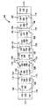
図1Aは、本発明の様々な態様に従った、構造体144(図1Dに図示)を形成するために使用される、例示的なブランク100の平面図である。本態様、および他の態様では、構造体144(図1D)は、輸送、保存、加熱、給仕中、略鉛直の、直立した構成で、1つ以上の食品を支持するために使用することができる。このようにして、アイテムは互いにおおむね分離され、それによって、食品の損傷を最小限に抑え、食品の加熱を容易にする。
【0012】
図1Aを見ると、ブランク100は、横方向の背折り線106に沿って、折り畳み可能に接続される、複数の第1および第2の分離パネル102、104を含む、略細長のストリップ片である。分離パネル102、104は、ブランク100から直立する構造体144(図1D)内に、仕切り壁146を形成する対108内に配列される。図1Aの例示的なブランク100は、ベースパネル110、または112によって互いに接続される、隣接するパネルの対108を有する、5つのパネルの対108を含む。しかしながら、構造体144内で保存、または加熱される食品の数によって、より少ない、またはより多くのパネルの対108を、必要に応じて含むことができる。末端のベースパネル114は、ブランク100の各端部で、パネルの対108に折り曲げ可能に接続される。端部パネル116は、ブランク100の各端部で、折り曲げ可能に接続されてもよい。ブランク100は、長手方向の中心線CLに対して、全体的または部分的に対称であってもよい。
【0013】
例示的な実施形態では、1つのベースパネル110は、ベースパネル112の左側に位置し、それは横方向の中心線CTに対して対称であり、2つのベースパネル110は、対称のベースパネル112の右側に位置する。ベースパネル112の左側のベースパネル110は、右側のベースパネル110のミラーイメージである。同様に、対称のベースパネル112の左側の、分離パネルの対108は、対称のベースパネル112の右側の、分離パネルの対108のミラーイメージである。
【0014】
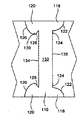
ベースパネル110は、各パネル110の各端部で、第1および第2の固定機能部118、120を含む。各第1の固定機能部118は、横方向のカット124と同一延長であってもよい曲線または弓形カット122によって、一部分において画定される。当然のことながら、ここに開示される各カットは、より正確には、スリットの形であってもよい。
【0015】
各第2の固定機能部120は、曲線または弓形カット126、および曲線カット126の端部から延在する傾斜カット128によって、一部分において画定される。曲線カット126、および傾斜カット128は、第2の固定機能部120の固定突起130を画定する。ベースパネル110の細長く、略長方形の中心部分132は、横方向の折り線134に沿って、隣接する第1の分離パネル102に、折り曲げ可能に接続され、横方向の折り線138に沿って、隣接する第2の分離パネル104に、折り曲げ可能に接続される。
【0016】
対称のベースパネル112は、パネル112の各端部で、一対の第1の固定機能部118を有してもよい。さらに、対称のベースパネル112は、横方向の折り線138に沿って、隣接する第2の分離パネル104に、折り曲げ可能に接続される、細長く、略長方形の中心部分136を含む。同様に、末端のベースパネル114の細長く、略長方形の中心部分140は、横方向の折り線134に沿って、隣接する第1の分離パネル102に、また横方向の折り線142に沿って、隣接する端部パネル116に、折り曲げ可能に接続される。第2の固定機能部120は、末端のベースパネル114のそれぞれの各端部に位置する。
【0017】
当然のことながら、ここに記載され、またはこれによって考慮される様々な折り線のいずれも、それに沿ったブランクの折り、または曲げを容易にする、必ずしも一直線とは限らないが、いかなる実質的に線状の寸断、または弱化形態であってもよい。例えば、横方向の折り線134、138、および142は、カット・クリース線として、図1Aに、概略的に示される。しかしながら、かかる線、およびここでの他の線のいずれも、スコア線、クリース線、部分的に、または完全に、望ましい弱化線に沿って、材料に延在するカット、もしくは一連のカット、またはこれらの特徴の様々な組合せであってもよい。
【0018】
図1A−1Dを参照して、構造体144をブランク100から組み立てる、例示的な一方法をここで考察する。図1Cに示されるように、ブランク100の端部は、ブランク100が、横方向の折り線134、および138に沿って折り曲げられるように、矢印の方向に、互いに向かって進められる。同時に、分離パネル102、104は、横方向の背折り線106に沿って、互いに折り畳む。
【0019】
ベースパネル110および112が、互いに近づけられると、ベースパネル110の一側面にある第2の固定機能部120は、横方向の折り線138に沿って延在する、カット124を介してスライドする。分離パネル102および104が、接している、またはほぼ接しているとき、第2の固定機能部120の固定突起130は、固定機能部118を被覆する固定機能部120によって、図1Cおよび1Dに示される、重複し、連結される位置で、ベースパネル110および112を維持する。ベースパネル110および112が係合された状態で、分離パネル102および104は、鉛直、または略垂直であり、分離壁146を形成する。同様に、さらなる分離壁146が、ブランク100の他の分離パネルの対108から、形成されてもよい。
【0020】
図1Dは、分離壁146に形成されるパネルの対108、および横方向の折り線142に対して上方に折られる、端部パネル116のそれぞれを有する、図1Aのブランク100から形成される、例示的な構造体144を図解する。分離壁146、および垂直な端部パネル116は、1つ以上の食品Fが、略鉛直、直立の構成で収納することができる、複数のレセプタクルスロット148(アコーディオン形状に略類似してもよい)を集合的に形成する。図1Dの前方にある端部パネル116は、一番手前のレセプタクルスロット148内の食品Fの一部を図解するために、部分的に切り取られて示される。ブランク100の連結されるベースパネル110、112、および114は、食品が構造体144に設置することができる、ベース150を形成する。
【0021】
本発明の一態様に従って、構造体144は、のり、または他の接着剤を使用せず、ブランク100から組み立てることができる。別の態様に従って、構造体144が組み立てられた後、構造体144を平坦に輸送することができるように、分離壁146、および端部パネル116を折り曲げることが可能である。
【0022】
必要に応じて、構造体144は、図1Dに示すように、外側コンテナ、またはカートン152内に置かれてもよい。このようにして、1つ以上の食品は、様々な食品の輸送、または販売前に、構造体144のレセプタクルスロット148内に、位置付けられてもよい。本実施例では、カートン152は、対向側壁154,端壁156、底壁158、および構造体144が、カートン152内に置かれるオープントップ160を有する、略平行六面体の構造である。しかしながら、他のカートンの形状、および構成が、これによって考慮される。本明細書において、当然のことながら、「パネル」、「ベース」、または「壁」は、平坦、または平面である必要はない。例えば、「パネル」、「ベース」、または「壁」は、複数の相互接続した略平坦、または平面部分を含むことができる。必要に応じて、カートン152は、カートンの様々な壁が、垂直で固定された位置で、構造体144を維持しやすくするように、寸法決定されてもよい。
【0023】
本発明の本態様、および他の態様では、様々なブランク、構造体、またはコンテナのすべて、または一部は、例えば、板紙材料から少なくとも部分的に形成されてもよい。例えば、様々なブランク、構造体、またはコンテナは、約60から約330lbs/ream(lbs/3000sq.ft)、例えば、約80から約140lbs/reamの坪量を有する、板紙から形成されてもよい。板紙は、概して、約6から約30mil、例えば、約12から約28milの厚さを有してもよい。特定の一実施例では、板紙は、約12milの厚さを有する。例えば、Graphic Packaging Internationalから市販の、SUS(登録商標)板などの、無地漂白(solid bleached)、または無地無漂白クラフト板紙(solid unbleached sulfate board)など、いかなる適した板紙が使用されてもよい。
【0024】
あるいは、様々なブランク、構造体、またはコンテナは、約15から約60lbs/ream、例えば、約20から約40lbs/reamの坪量を概して有する紙、または紙から作られる材料を含んでもよい。特定の一実施例では、紙は、約25lbs/reamの坪量を有する。
【0025】
必要に応じて、1つ以上のマイクロ波エネルギー相互作用要素は、本発明の様々なブランク、または構造体のいずれの少なくとも一部を被覆したり、結合されてもよい。各マイクロ波相互作用要素は、特定のマイクロ波加熱の利用の必要、または要求に応じて、マイクロ波エネルギーを吸収、マイクロ波エネルギーを伝達、マイクロ波エネルギーを反射、またはマイクロ波エネルギーを方向付けるために、特定の構成で配列される、1つ以上のマイクロ波エネルギー相互作用材料、または区分を含んでもよい。結果として、要素の1つ以上は、食品に焦げ目をつけたり、カリカリに仕上げることを容易にし、その範囲内の食品を加熱し過ぎることを防止するために、マイクロ波エネルギーから食品を遮蔽する、または食品の特定の部分に、またはそこからマイクロ波エネルギーを伝達することができる。
【0026】
必要に応じて、マイクロ波相互作用要素は、取り扱いを容易にするために、また、マイクロ波相互作用材料と食品間の接触を防止するために、マイクロ波不活性、または透過基板上で支持されてもよい。限定ではなく利便性の問題として、またマイクロ波透過基板上で支持されるマイクロ波相互作用要素は、マイクロ波相互作用、およびマイクロ波不活性要素、またはコンポーネントの両方を含むことが理解されるが、かかる構造は、ここで、「マイクロ波相互作用ウェブ」と呼ばれる。
【0027】
マイクロ波エネルギー相互作用材料は、例えば、金属箔として提供される金属、もしくは金属合金;真空蒸着金属、もしくは金属合金;または金属インキ、有機インキ、無機インキ、金属ペースト、有機ペースト、無機ペースト、またはそれらのいかなる組合せなどの電気伝導性、または半導体材料を含んでもよい。本発明での使用に適している可能性のある金属、または金属合金の例は、アルミニウム、クロム、銅、インコネル合金(ニオブを有する、ニッケル−クロム−モリブデン合金)、鉄、マグネシウム、ニッケル、ステンレス鋼、スズ、チタニウム、タングステン、およびそれらのいかなる組合せ、または合金を含むが、それらに限定されない。
【0028】
あるいは、マイクロ波エネルギー相互作用材料は、金属酸化物を含んでもよい。本発明での使用に適している可能性のある金属酸化物の例は、必要であれば、導電性材料と合わせて使用される、アルミニウム、鉄、およびスズの酸化物を含むが、それらに限定されない。本発明での使用に適している可能性のある金属酸化物の別の例は、インジウムスズ酸化物(ITO)である。ITOは、加熱効果、遮蔽効果、焦げ目をつけたり、カリカリに仕上げる効果、またはそれらの組合せを提供するために、マイクロ波エネルギー相互作用材料として使用することが可能である。例えば、サセプタを形成するために、ITOは、透過高分子フィルム上にスパッタされてもよい。スパッタプロセスは、通常、金属堆積のために使用される蒸発堆積よりも、低い温度で起こる。ITOは、より均一の結晶構造を有し、したがって、最もコーティングが厚い部分でも透過性である。さらに、ITOは、加熱、または領域管理効果(field management effect)のいずれかに使用することができる。また、ITOは、金属よりも少ない欠陥を有することができ、したがって、ITOの厚いコーティングを、アルミニウムなどの金属の厚いコーティングよりも、領域管理に適したものにする。
【0029】
あるいは、マイクロ波エネルギー相互作用材料は、適した電気伝導性、半導体、または非導電性人工誘電体、または強誘電体を含んでもよい。人工誘電体は、高分子、または他の適したマトリクス、またはバインダー内に、導電性の細分化材料を有し、例えばアルミニウムなどの電気伝導性金属のフレークを含んでもよい。
【0030】
一実施例では、マイクロ波相互作用要素は、マイクロ波エネルギーを吸収する傾向がある、マイクロ波相互作用材料の薄層を含むことができ、したがって、食品との共通領域で熱を生成する。かかる要素は、食品の表面に焦げ目をつけたり、カリカリに仕上げることを促進するために、頻繁に使用される(時に、「焦げ目をつけたり、カリカリに仕上げる要素」と呼ばれる)。フィルム、または他の基板上で支持されるとき、かかる要素は、「サセプタフィルム」、または単に「サセプタ」と呼ばれてもよい。
【0031】
別の実施例として、マイクロ波相互作用要素は、食品の1つ以上の選択された部分を、マイクロ波エネルギーから遮蔽するために十分な厚さを有する、箔を含んでもよい(時に、「遮蔽要素」と呼ばれる)。かかる遮蔽要素は、食品が加熱中に焦げ付く、または乾燥する傾向がある場合に、使用されてもよい。
【0032】
遮蔽要素は、遮蔽要素が使用される特定の用途によって、様々な材料から形成されてもよく、様々な構成を有してもよい。通常、遮蔽要素は、例えば、アルミニウム、銅、またはステンレス鋼などの、伝導性、反射性金属、または金属合金から形成される。遮蔽要素は、約0.000285inchから約0.05inchの厚さを、概して有することができる。一態様では、遮蔽要素は、約0.0003inchから約0.03inchの厚さを有する。別の態様では、遮蔽要素は、約0.00035inchから約0.020inch、例えば、0.016inchの厚さを有する。
【0033】
さらに別の実施例として、マイクロ波相互作用要素は、米国特許第6,204,492号、6,433,322号、6,552,315号、および6,677,563号に記載されるような、しかしそれらに限定されない分割箔を含んでもよく、そのそれぞれは、その全体で、参照することによって組み込まれる。分割箔は連続的ではないが、かかる区分の適切に離間した組み分けは、頻繁に、マイクロ波エネルギーを食品の特定の領域に方向付けするための、伝達要素の機能を果たす。また、かかる箔は、例えばサセプタなど、焦げ目をつけたり、カリカリに仕上げる要素との組合せで使用されてもよい。
【0034】
前述の通り、本発明に従って使用される、上記のマイクロ波エネルギー相互作用要素のいずれも、基板上で支持されてもよい。基板は通常、例えば、重合体、または高分子材料から形成されるフィルムなどの、電気絶縁体を含む。ここで使用されるように、用語「重合体」、または「高分子材料」は、単独重合体、例えば、ブロック、グラフト、ランダム、および交互共重合体、三元重合体などの共重合体、ならびにそれらの混合、および組み換えを含むが、それらに限定されない。さらに、別段の具体的な限定がない限り、用語「重合体」は、分子のすべての可能な幾何学的構成を含むものとする。これらの構成は、イソタクチック、シンジオタクチック、およびランダム対称を含むが、それらに限定されない。
【0035】
フィルムの厚さは、通常、約35gaugeから、約10milであることが可能である。一態様では、フィルムの厚さは、約40から約80gaugeである。別の態様では、フィルムの厚さは、約45から約50gaugeである。さらに別の態様では、フィルムの厚さは、約48gaugeである。適している可能性のある高分子フィルムの例は、ポリオレフィン、ポリエステル、ポリアミド、ポリイミド、ポリスルホン、ポリエーテルケトン、セロファン、またはそれらのいかなる組合せを含むが、それらに限定されない。また、紙およびラミネート紙、金属酸化物、ケイ酸塩、 セルロース、またはそれらのいかなる組合せなどの、他の非導電基板材料が使用されてもよい。
【0036】
高分子フィルムは、例えば、印刷適性、耐熱性、またはいかなる他の特性などの様々な特性を、マイクロ波相互作用ウェブに与えるために、選択されてもよい。一実施例では、高分子フィルムは、ポリエチレンテレフタレート(PET)を含む。ポリエチレンテレフタレートフィルムには、例えば、共にGraphic Packaging International(Marietta,Georgia)から入手可能の、QWIKWAVE(登録商標)Focusサセプタ、およびMICRORITE(登録商標)サセプタなどの、市販されているサセプタが使用される。基板としての使用に適している可能性のある、ポリエチレンテレフタレートフィルムの例は、DuPont Teijan Films(Hopewell,Virginia)から市販されているMELINEX(登録商標)、SKC,Inc.(Covington,Georgia)から市販されているSKYROL、およびToray Films(Front Royal,VA)から市販されているBARRIALOX PET、ならびにToray Films(Front Royal,VA)から入手可能のQU50 High Barrier Coated PETを含むが、それらに限定されない。
【0037】
マイクロ波エネルギー相互作用材料は、いかなる適した方法で、基板に加えられてもよく、場合によっては、マイクロ波エネルギー相互作用材料は、基板上に印刷、押出、スパッタ、蒸着、またはラミネート加工される。マイクロ波エネルギー相互作用材料は、食品の望ましい加熱効果を達成するために、いかなるパターンで、およびいかなる技術を使用して、基板に加えられてもよい。
【0038】
例えば、マイクロ波エネルギー相互作用材料は、円、輪、六角形、島、正方形、長方形、八角形などの、連続または不連続層、またはコーティングとして提供することができる。本発明での使用に適している可能性のある様々なパターン、および方法の例は、米国特許第6,765,182号、第6,717,121号、第6,677,563号、第6,552,315号、第6,455,827号、第6,433,322号、第6,414,290号、第6,251,451号、第6,204,492号、第6,150,646号、第6,114,679号、第5,800,724号、第5,759,422号、第5,672,407号、第5,628,921号、第5,519,195号、第5,424,517号、第5,410,135号、第5,354,973号、第5,340,436号、第5,266,386号、第5,260,537号、第5,221,419号、第5,213,902号、第5,117,078号、第5,039,364号、第4,963,424号、第4,936,935号、第4,890,439号、第4,775,771号、第4,865,921号、および第Re.34,683号において提供され、そのそれぞれは、その全体で、本願で参照することによって組み込まれる。マイクロ波エネルギー相互作用材料のパターンの特定の例は、ここに示され、記載されるが、マイクロ波エネルギー相互作用材料の他のパターンが、本発明によって考慮されることは、理解されるものとする。
【0039】
限定ではなく、実施例として、図1Eは、図1Eのブランク162が、様々なパネルの実質的にすべてを被覆している、マイクロ波エネルギー相互作用要素164を含む以外は、図1Aのブランク100と同様のブランク162を示す。本実施例では、マイクロ波エネルギー相互作用要素164は、サセプタを含み、より詳しくは、図1Fの略断面図に示されるような、高分子フィルム168上に支持される、マイクロ波エネルギー相互作用材料166を含む、サセプタフィルムを含む。マイクロ波エネルギー相互作用材料166の層は、高分子フィルム168と、ブランク162の様々なパネルを形成する、板紙支持170の間に配置される。サセプタフィルム164は、いかなる適した方法で、例えば、接着剤の連続、またはパターン層(不図示)を使用して、支持に結合することができる。しかしながら、他のマイクロ波エネルギー相互作用要素が、これによって考慮される。
【0040】
構造体は、上述の方法で、ブランク162から形成することができ、マイクロ波エネルギー相互作用要素164、本実施例では、サセプタが、様々なパネルの食品接触面を被覆する以外は、図1Dの構造体と同様であろう。
【0041】
ブランクから組み立てられる構造体を使用するために、1つ以上の食品は、構造体に入れられ、任意に、図1Dにおおむね示されるような、外側コンテナ内に置かれる。食品は、消費前にこの状態のままでいてもよい。食品またはアイテムが、加熱される状態にあるとき、任意に外側コンテナ内にある構造体は、電子レンジ(不図示)内に置かれてもよい。加熱サイクルの間、食品は、サセプタと近接または密接触したままである。サセプタは、マイクロ波エネルギーを熱エネルギーに変換し、次に、それは、隣接する食品に移動することができる。結果として、食品またはアイテムの加熱、焦げ目をつけたり、カリカリに仕上げることを、増強することができる。
【0042】
必要に応じて、コンテナの内側表面もまた、電子レンジの食品への効果をさらに強化、または変更するために、1つ以上のマイクロ波エネルギー相互作用要素(不図示)を含むことができる。
ここに記載される、またはこれによって考慮される、多数のマイクロ波相互作用要素のいずれも、実質的に連続的である、つまり、実質的割れ目、もしくは隙間がなくてもよく、または例えば、そこを介してマイクロ波エネルギーを伝達する1つ以上の途切れ、または隙間を含むことによって、不連続的であってもよい。割れ目、または開口は、食品の特定の領域を選択的に加熱するために、大きさが決められ、位置付けられてもよい。かかる割れ目、または開口の数、形状、サイズ、および位置付けは、形成される構造体の種類、この中、またはこの上で加熱される食品、遮蔽の望ましい度合い、焦げ目をつけたり、カリカリに仕上げること、食品の均一な加熱を達成するために、マイクロ波エネルギーの直接照射が必要である、または望ましいかどうか、直接加熱中の食品の温度変化を調整する必要性、ならびに通気の必要性があるかどうか、およびどの程度あるかによって、特定の用途で異なってもよい。
【0043】
当然のことながら、開口は、ブランク、または構造体を形成するために使用される材料内で、物理的開口、または孔隙であってもよく、または非物理的「開口」、または途切れであってもよい。非物理的開口は、不活性化によって、マイクロ波エネルギー不活性ブランク、または構造体の一部、または、マイクロ波エネルギーを通すものであってもよい。したがって、例えば、開口は、マイクロ波エネルギー活性材料なしで形成されるブランク、または構造体の一部であってもよい、あるいは、取り除かれた、または不活性化された、マイクロ波エネルギーが活性な材料で形成されるブランク、または構造体の一部であってもよい。物理的、および非物理的開口、または途切れの両方が、食品が、マイクロ波エネルギーによって、直接加熱されることを可能にする一方で、物理的開口は、湯気や他の蒸気が食品から放出され、取り除かれることを可能にする、通気機能も提供する。
【0044】
構造体の過熱または焦げを防止するために、1つ以上の途切れ、または不活性領域を作成することもまた、有益であり得る。限定ではなく例として、図1Eに図示されるブランク162において、例えば、パネル102および104などの、隣接するパネルの縁に沿って生成される、熱の集中状態は、例えば板紙などの下層支持が焦げる原因となるに、十分であり得る。そのようなものとして、パネル102、104や、110の1つ以上の周辺部は、例えば、マイクロ波エネルギー相互作用材料なしで、これらの領域を形成することによって、またはこれらの領域内のマイクロ波エネルギー相互作用材料を不活性化することによって、マイクロ波不活性に設計することができる。その上、1つ以上のパネル、パネルの一部、または構造体の一部は、マイクロ波エネルギーが、焦げ目をつけたり、カリカリに仕上げられることを目的としていない食品の部分、または加熱環境に失われるよりも、焦げ目をつけたり、カリカリに仕上げられる領域に、効果的に集中することを確実にするために、マイクロ波エネルギー不活性に設計することができる。例えば、図1Gに示される例示的なブランク172において、例えば、異なるサイズの、マイクロ波エネルギー不活性サセプタ「パッチ」などの、複数のマイクロ波エネルギー相互作用要素164は、パネル102および104のそれぞれの非周辺部を被覆するが、パネル110を被覆しない。多数の他の構成が、本発明によって考慮される。
【0045】
図2は、本発明の様々な態様に従って、別の例示的なブランク200を示す。ブランク200は、「1」の代わりに「2」が前に付き、図1Aの要素と同様、または同一の要素を有し、図1Aに示されるブランク100と実質的に同様であってもよい。ブランク200は、長手方向の中心線CLに対して、全体的に、または部分的に対称であってもよい。
【0046】
図2を参照すると、ブランク200は、横方向の背折り線206に沿って、折り畳み可能に接続される複数の第1、および第2の分離パネル202、204を含む、細長のストリップ片である。分離パネル202、204は、組み立てられた構造体(不図示)内に仕切り壁を形成する、対208内に配置される。例示的なブランク200は、ベースパネル210、または212で互いに接続される、隣接するパネルの対208を有する、5つのパネルの対208を含む。末端のベースパネル214は、ブランク200の各端部で、パネルの対208に折り曲げ可能に接続される。端部パネル216は、ブランク200の各端部で、折り曲げ可能に接続されてもよい。
【0047】
図2の第2の固定機能部220は、図1Aに図解される第2の固定機能部120と実質的に同一であってもよい。第1の固定機能部218は、曲線カット222のそれぞれの端部から延在するカット224が、傾斜カットである以外は、図1Aに図解される固定機能部118と同様であってもよい。傾斜カット224、および曲線カット222は、隣接するベースパネルを固定するために、第2の固定機能部220内に、対応する固定突起230を係合する、固定突起262を画定する。例えばサセプタなどの、マイクロ波エネルギー相互作用要素264は、ブランク200のすべて、または一部を被覆してもよい。
【0048】
ブランク200は、構造体に組み立てられてもよく、図1A−Gを参照して上述される方法で、使用されてもよい。さらに、構造体は、図1Dに関連して記載されるような1つ以上の食品を収容する、加熱する、焦げ目をつける、またはカリカリに仕上げるため、上述のようなカートン、または他のコンテナと併せて使用されてもよい。
【0049】
図3Aは、本発明に対する参考例として例示するブランク300を図解する。ブランク300は、「1」の代わりに「3」が前に付き、図1Aの要素と同様、または同一の要素を有し、図1Aに図解されるブランク100と実質的に同様であってもよい。ブランク300は、長手方向の中心線CLに対して、全体的に、または部分的に対称であってもよい。
【0050】
図3Aを参照すると、ブランク300は、横方向の背折り線306に沿って、折り畳み可能に接続される複数の第1、および第2の分離パネル302、304を含む、略細長のストリップ片である。分離パネル302、304は、組み立てられる構造体344(図3C)内に仕切り壁346を形成する、対308内に配置される。本実施例では、ブランク300は、ベースパネル310によって互いに接続される、隣接する分離パネルの対308を有する、5つのパネルの対308を含む。構造体344内で保存、加熱される食品の数によって、必要に応じて、より少ない、または追加のパネルの対308を含むことができる。末端のベースパネル316は、ブランク300の各端部で、パネルの対308に折り曲げ可能に接続される。
【0051】
ベースパネル310は、各パネル310の一側面に第1の固定機能部318を、また第2の側面に第2の固定機能部320を有する、略長方形の細長い部分である。各第1の固定機能部318は、カット322の各端部から延在する横方向のカット324と、実質的に同一延長であってもよい曲線または弓形カット322によって、画定される。各第2の固定機能部320は、曲線または弓形カット326、および曲線カット326の各端部から内側に延在する、傾斜カット328によって画定される。弓形カット326、および傾斜カット328は、第2の固定機能部320の各側面上に、固定突起330を画定する。図3Aでは、固定機能部318、320は、ブランク300の長手方向の中心線CLに沿って配置されるように、図解される。しかしながら、端部から離れたブランク300内のいかなる内側の位置も、固定機能部318、320に適している可能性がある。
【0052】
ベースパネル310は、横方向の折り線334に沿って、隣接する第1の分離パネル302に折り曲げ可能に接続され、それは、第2の固定機能部320によって遮断される。同様に、ベースパネル310は、横方向の折り線336に沿って、隣接する第2の分離パネル304に折り曲げ可能に接続され、それは、第1の固定機能部318によって遮断される。
例えばサセプタなどの、マイクロ波エネルギー相互作用要素364は、ブランク300のすべて、または一部を被覆してもよい。
【0053】
ブランク300から構造体344を組み立てる、例示的な一方法は、図3Bおよび3Cに図解される。図3Bに示されるように、隣接するベースパネル310は、ブランク300が、横方向の折り線334、336に沿って折り曲げられるように、矢印の方向に、互いに向かって進められる。同時に、分離パネル302、304は、横方向の背折り線306に沿って、互いに折り畳まれる。
【0054】
隣接するベースパネル310が、互いに近づけられると、第1の固定機能部318、および第2の固定機能部320は、それぞれの分離パネル304、および302からぶつかり、第2の固定機能部320は、カット322、および324によって画定される開口を介してスライドする。第2の固定機能部320の固定突起330は、固定機能部318を被覆する固定機能部320によって、図3Bに示される、重複し、連結される位置で、ベースパネル310を維持する(図からは隠されている)。本構成では、分離パネル302、304は、鉛直、または略垂直の分離壁346を形成する。同様に、さらなる分離壁346が、ブランク300の他の分離パネルの対308から、形成されてもよい。
【0055】
図3Cは、図3Aのブランク300から形成される、例示的な構造体344を示す。分離壁346は、食品(不図示)を収納することができる、一連のレセプタクルスロット348を形成する。ブランク300の連結されたベースパネル310は、構造体344のベース350を形成する。必要に応じて、図1Cに関連して記載されるように、輸送前にカートン、または他のコンテナ内に構造体344を置くことができる。特に、構造体344は、接着剤の使用を必要とすることなく、ブランク300から組み立てることができ、必要に応じて、ベース350に向かって分離壁346を折り曲げることによって、平坦に輸送することができる。構造体344は、その中で様々な食品を保存する、加熱する、焦げ目をつけたり、カリカリに仕上げるために、上述の方法で使用されてもよい。
【0056】
図4Aは、本発明に対する参考例として例示するブランク400を図解する。ブランク400は、例えば、図4Bに図解される構造体444などの、構造体を形成するために使用される。ブランク400は、「1」の代わりに「4」が前に付き、図1Aの要素と同様、または同一の要素を有し、図1Aに図解されるブランク100と実質的に同様であってもよい。ブランク400は、長手方向の中心線CLに対して、全体的に、または部分的に対称であってもよい。
【0057】
図4Aを参照すると、ブランク400は、横方向の背折り線406に沿って、折り畳み式に接続される複数の第1、および第2の分離パネル402を含む、略細長のストリップ片である。分離パネル402は、ブランク400から組み立てられる構造体444(図4B)内に仕切り壁446を形成する、対408内に配置される。例示的なブランク400は、横方向の折り線434に沿って、ベースパネル410によって互いに接続される、隣接するパネルの対408を有する、5つの分離パネルの対408を含む。しかしながら、構造体444によって加熱される食品の数によって、より少ない、または追加の分離パネルの対408を含むことができる。分離パネル402、およびベースパネル410は、略長方形の形状である。
【0058】
例えばサセプタなどの、マイクロ波エネルギー相互作用要素464は、ブランク400のすべて、または一部を被覆してもよい。
ブランク400から構造体444を形成するために、ブランク400の端部は、隣接する分離パネル402が、横方向の背折り線406に沿って、互いに向かって折り畳めるように、互いに向かって押し進められる。同時に、ブランク400は、分離パネル402が、図4Bに示される略垂直の位置を取るように、横方向の折り線434に沿って折り曲げられる。本構成では、分離パネルの対408は垂直であり、食品Fが収納される、複数のレセプタクルスロット448を画定する、分離壁446を形成する。特に、構造体444は、のり、または他の接着剤を使用せず、ブランク400から組み立てることができる。別の態様に従って、構造体444が組み立てられた後、分離壁446は、構造体を平坦に輸送することができるように、折り曲げられてもよい。
【0059】
必要に応じて、構造体は、カートン452内に置かれてもよく、それは、組み立てられた構成で、構造体444の形状を保持しやすくするために、寸法決定されてもよい。構造体444は、上記の様々な構造体に関連して記載される方法で、使用されてもよい。
【0060】
図5Aは、本発明に対する参考例として例示する別のブランク500を図解する。ブランク500は、長手方向の中心線CL周辺で、全体的に、または部分的に対称であってもよい。ブランク500は、横方向の背折り線506に沿って、折り畳み可能に接続される複数の第1、および第2の分離パネル502、504を含む、略細長のストリップ片である。分離パネル502、504は、ブランク500から組み立てられる構造体544(図5C)内に、仕切り壁546を形成する、分離パネルの対508内に配置される。例示的なブランク500は、ベースパネル510で互いに接続される、隣接するパネルの対508を有する、5つの分離パネル508を含む。しかしながら、構造体544内で保存、加熱される食品の数によって、より少ない、または追加の分離パネル508を含むことができる。
【0061】
ベースパネル510は、横方向の折り線534に沿って、隣接する第1の分離パネル502に折り曲げ可能に接続され、横方向の折り線536に沿って、隣接する第2の分離パネル504に折り曲げ可能に接続される、細長く、略長方形の部分である。
【0062】
固定機能部518は、ブランク500の上部、および下部周縁領域に位置する。固定機能部518は、長手方向の折り線566に沿って、ベースパネル510の1つの各端部に、それぞれ折り畳み可能に接続される。各固定機能部518は、ベース570から延在する複数の固定突起568を含む。固定機能部518は、細長いクリアランス開口572によって互いに分離される。各固定機能部518のベース570は、長手方向のカット574によって、それぞれの隣接する分離パネル502、504から分離される。クリアランス切り抜き576、578は、分離パネル502、504内に形成される。クリアランス切り抜き576、578は、図5Bを参照して以下でさらに考察されるように、固定機能部518が、折り線566に対して内側に折り畳まれることを可能にする。
【0063】
例えばサセプタなどの、マイクロ波エネルギー相互作用要素564は、ブランク500のすべて、または一部を被覆してもよい。
ブランク500から構造体544を形成するために、ブランク500の端部は、隣接する分離パネル502、504が、折り線506、534、および536に沿って、互いに向かって折り曲げられるように、同時に押し進められる。その際、分離パネル502、504は、図5Bに示されるように、略垂直の位置を取り、分離壁546を形成する。次に、固定機能部518は、固定機能部518が、図5Cに示されるように、平坦に折り畳まれるまで、曲線矢印の方向に、長手方向の折り線566に対して、内側に180度折り畳まれる。分離パネル502、504内のクリアランス切り抜き576、578は、固定機能部518のベース570が、構造体の残りの部分の妨げとなることなく、折り重なることを可能にする。垂直の分離壁546は、固定機能部518内の、クリアランス開口572を通過する。
【0064】
分離壁546は、食品(不図示)を収納することができる、複数のレセプタクルスロット548を形成する。構造体544は、のり、または他の接着剤を使用せず、ブランク500から組み立てられることができる。構造体は、電子レンジ内で、1つ以上の食品を収容する、および任意に加熱する、焦げ目をつけたり、カリカリに仕上げるために、様々な他の構造体に関して上述される方法で、使用することができる。
【0065】
当然のことながら、状況次第で、特に、食品が、焦げ目をつけたり、カリカリに仕上げることが困難な、凸凹した表面を有する場合、ブランク、構造体、または外側カートンは、マイクロ波エネルギー交互作用絶縁材料を有する、マイクロ波エネルギー相互作用要素を含んでもよい。ここで使用されるように、用語「マイクロ波エネルギー交互作用絶縁材料」、もしくは「マイクロ波エネルギー交互作用絶縁構造」、または「絶縁材料」、もしくは「絶縁構造」は、例えば紙層、高分子フィルム層、およびマイクロ波エネルギー相互作用要素などの、材料の層のいかなる組合せを意味し、それは、マイクロ波エネルギーに対する反応性を有し、また、食品を加熱するために使用されるとき、ある程度の断熱を提供することもできる。絶縁材料は、例えば、様々な形で示されるサセプタの代わりに、様々なブランク、構造体、またはカートンの、様々な食品接触領域のすべて、または一部を被覆してもよい。しかしながら、絶縁材料の他の位置が、これによって考慮される。
【0066】
絶縁材料は、それぞれが、通常の電子レンジの加熱温度、例えば、約250°Fから約425°Fで、軟化、焼け付き、燃焼、または劣化に耐性を有するという条件で、様々なコンポーネントを含んでもよい。絶縁材料は、マイクロ波エネルギー反応性、または相互作用コンポーネント、およびマイクロ波エネルギー透過、または不活性コンポーネントの両方を含んでもよい。
【0067】
一態様では、絶縁材料は、1つ以上の膨張性絶縁セルとの組合せで、1つ以上のサセプタ層を含む。かかる材料は、「膨張性セル絶縁材料」と呼ばれてもよい。さらに、絶縁材料は、寸法安定性を提供するために、マイクロ波エネルギー相互作用材料の取り扱い易さを改善するために、また、マイクロ波エネルギー相互作用材料と食品間の接触を防止するために、1つ以上のマイクロ波エネルギー透過、または不活性材料を含んでもよい。例えば、絶縁材料は、第1の高分子フィルム層上に支持される、マイクロ波エネルギー相互作用材料、マイクロ波エネルギー相互作用材料と重ね合わせられる、水分含有層、および所定のパターンで水分含有層に結合される、第2の高分子フィルム層を含んでもよく、それによって、水分含有層と第2の高分子フィルム層の間に、1つ以上の閉塞セルを形成する。閉塞セルは、マイクロ波エネルギーの照射に反応して、膨張または膨大し、それによって、マイクロ波エネルギー相互作用材料が、膨隆および変形する原因となる。
【0068】
いくつかの例示的な絶縁材料が、図6A乃至10に描写される。ここに示される実施例のそれぞれにおいて、当然のことながら、層の幅は、必ずしも遠近法によって示されるとは限らない。実施例として、いくつかの層は、他の層に対して非常に薄い可能性があるが、それにもかかわらず、層の配列を明確に図解する目的で、多少の厚さで示される。
【0069】
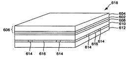
図6Aは、本発明に従って使用することができる、例示的な絶縁構造、または材料600を描写する。本実施例では、マイクロ波エネルギー相互作用材料の薄層602は、第1の高分子フィルム604(サセプタ606を集合的に含む)上で支持され、例えば紙などの、寸法的に適した基板610に、接着剤608(または別の方法)でラミネート加工することによって、接合される。基板610は、閉塞、膨張性セル616(それぞれ、孔隙として示される)が、材料600内に形成されるように、パターン化された接着剤614、または他の材料を使用して、第2の高分子フィルム612に接合される。絶縁材料600は、図6Bに示すように、カットされ、実質的に平坦な多層シート618として提供されてもよい。
【0070】
マイクロ波エネルギー相互作用材料602が、マイクロ波エネルギーによって衝突加熱すると、図6Cに示されるように、例えば紙などの基板610内で、通常保持される水蒸気、または他の気体、および閉塞セル616内の第2の高分子フィルム612と基板610の間の薄い空間に閉じこめられた、空気が膨張する。その結果として得られた絶縁材料618’は、キルト状、または枕状の上部表面620、および下部表面622を有する。マイクロ波加熱が停止すると、セル626は、通常収縮し、若干平坦な状態に戻る。
【0071】
図7は、本発明に従って使用することができる、別の例示的なマイクロ波エネルギー相互作用絶縁構造、または材料700を図解する。図6Aに図解される構造600と非常に似ており、図7の構造700は、第1の高分子フィルム704上に支持される、マイクロ波エネルギー相互作用材料702の薄層を含み、それは、サセプタ706を集合的に含む。サセプタ706は、例えば紙などの寸法的に適した基板710に、接着剤708、または別の方法で、ラミネート加工することによって接合され、それは同様に、複数の閉塞、膨張性セル716(孔隙として示される)を形成するために、パターン化された接着剤714、または他の材料を使用して、第2の高分子フィルム712に接合される。しかしながら、本実施例では、構造700は、さらなる寸法安定性を提供するために、また構造700からの、マイクロ波エネルギー相互作用材料702のいかなる剥離も防止するために、接着剤の層720、または他の適した材料を使用して、構造の残りの部分に結合される、紙の追加層718を含む。
【0072】
図8は、本発明に従って使用することができる、さらに別の例示的な絶縁構造、または材料800を描写する。材料800は、パターン化された接着層によって、共に接着される2つの対称層配列を含む。図面の上部から始まる第1の対称層配列は、例えばポリエチレンテレフタレートなどの、高分子フィルム層802、金属層804、接着層806、および紙、または板紙層808を含む。金属層804は、高分子フィルム層802の少なくとも一部に沿って置かれる、アルミニウムなどの金属を含む。高分子フィルム層802、および金属層804は共に、サセプタを画定する。接着層806は、高分子フィルム層802、および金属層804を、板紙層808に接合する。
【0073】
図面の下部から始まる第2の対称層配列もまた、高分子フィルム層810、金属層812、接着層814、および紙、または板紙層816を含む。必要に応じて、2つの対称配列は、そのものに1つの層配列を折り曲げることによって、形成されてもよい。第2の対称層配列の層は、第1の対称配列の層と同様の方法で、共に接合される。パターン化された接着層818は、2つの紙層808と816の間に設けられ、マイクロ波エネルギーが照射するとき膨張するように構成される、閉塞セル820(それぞれ、孔隙として示される)のパターンを画定する。2つの金属層804、および812を有する、絶縁材料800を使用することによって、より多くの熱が生成され、したがって、より大きいセルのロフトを達成する。結果として、かかる材料は、その上に設置される食品を、単一のマイクロ波エネルギー相互作用材料層を有する絶縁材料よりも、大きい程度まで昇温する(elevate)ことができる。
【0074】
ここで図9を見てみると、さらに別の絶縁材料900が示される。材料900は、高分子フィルム層902、金属層904、接着層906、および紙層908を含む。さらに、材料900は、第2の高分子フィルム層910、接着剤912、および紙層914を含んでもよい。層は、複数の閉塞膨張性セル918(それぞれ、孔隙として示される)を画定するために、パターン化された接着剤916によって接着、または貼付される。
【0075】
図10は、さらに別の例示的な絶縁材料1000を描写する。本実施例では、1つ以上の試薬が、絶縁材料のセルを膨張させる気体を生成するために、使用される。図10に示される実施例では、マイクロ波相互作用材料の薄層1002は、サセプタフィルム1006を形成するために、第1の高分子フィルム1004上で支持される。任意にコーティング内にある、1つ以上の試薬1008は、マイクロ波相互作用材料の層1002の、少なくとも一部を被覆する。試薬1008は、閉塞セル1014(それぞれ、孔隙として示される)が、材料1000内で形成されるように、パターン化された接着剤1012、もしくは他の材料を使用して、または熱接合、超音波接合、もしくはいかなる他の適した技術を使用して、第2の高分子フィルム1010に結合される。
【0076】
マイクロ波相互作用材料1002が、マイクロ波エネルギーによって衝突加熱すると、水蒸気、または他の気体が、試薬1008から放出されるか、またはそれによって生成される。結果として得られた気体は、閉塞セル1014の一側面上のサセプタフィルム1006、および他の側面上の第2の高分子フィルム1010上に、圧力を印加する。閉塞セル1014を形成する材料1000の各側面は、キルト状の絶縁材料(図示しないが、図6Cの絶縁材料と同様の外観)を形成するために、加熱および蒸気膨張に同時に、しかし一意に反応する。この膨張は、電圧を印加した電子レンジ内で、1から15秒以内に起こる可能性があり、場合によっては、2から10秒以内に起こる可能性がある。紙、または板紙層がなくても、試薬から得られた水蒸気は、膨張性セルを膨大させる、およびマイクロ波エネルギー相互作用材料から、いかなる過剰熱も吸収するに十分である。
【0077】
当然のことながら、本発明の様々な絶縁材料は、電子レンジ内で食品を加熱する、焦げ目をつける、カリカリに仕上げることを増強する。はじめに、閉塞セル内に含まれる水蒸気、空気、および他の気体は、食品と電子レンジの周囲環境の間に絶縁を提供し、それによって、食品内にとどまる、または食品に移動される顕熱の量を増加する。さらに、セルの形成は、材料を食品の表面によりしっかりと適合することを可能にし、サセプタフィルムを食品により近接させ、それによって、焦げ目をつけたり、カリカリに仕上げることを増強する。さらに、絶縁材料は、電子レンジ内での調理中、食品内の水分を保持するのに役立つことができ、それによって、食品の質感および風味を改善する。かかる材料のさらなる利点および態様は、PCT出願第PCT/US03/03779号、米国出願第10/501,003号、および米国出願第11/314,851号に記載され、そのそれぞれは、その全体で、本願で参照することによって組み込まれる。
【0078】
ここに記載される、またはこれによって考慮される絶縁材料のいずれも、特定の食品の調理を増強するために選択される、接着パターン、または熱接合パターンを含んでもよい。例えば、食品がより大きいアイテムである場合、接着パターンは、実質的に均一形状の膨張性セルを形成するように、選択されてもよい。食品が小さいアイテムである場合、接着パターンは、アイテムが、その様々な表面上で可変的に接触されることを可能にするために、複数の異なるサイズのセルを形成するように、選択されてもよい。いくつかの実施例がここで提供されているが、当然のことながら、多数の他のパターンがこれによって考慮され、選択されるパターンは、特定の食品を加熱する、焦げ目をつける、カリカリに仕上げる、および絶縁する必要性による。
【0079】
必要に応じて、絶縁材料の多層は、絶縁材料の絶縁特性を増強するために使用されてもよく、したがって、食品に焦げ目をつける、およびカリカリに仕上げることを増強する。多層が使用される場合、層は、分離したままでもよく、または例えば、熱接合、 接着接合、超音波接合、もしくは溶接、機械的締め付け、またはそれらのいかなる組合せなどの、いかなる適したプロセス、または技術を使用して、結合されてもよい。一実施例では、絶縁材料2つのシートは、それらのそれぞれのサセプタフィルム層が、互いから見て外方に向くように、配列されてもよい。別の実施例では、絶縁材料2つのシートは、それらのそれぞれのサセプタフィルム層が、互いに向かい合うように、配列されてもよい。さらに別の実施例では、絶縁材料の多シートは、同様の方法で配列され、重ね合わせられてもよい。さらなる実施例では、様々な絶縁材料の多シートは、特定の用途の必要または要求に応じて、いかなる他の構成で重ね合わせられてもよい。
【0080】
任意に、ここに記載される、またはこれによって考慮される様々なブランク、構造体、またはシステムの1つ以上の部分は、ニス、粘土、または他の材料で、単独または組合せで、コーティングされてもよい。次に、コーティングは、製品広告、または他の情報もしくは画像で刷り重ねられてもよい。様々なブランク、構造体、またはシステムはまた、その上に印刷されるいかなる情報も保護するために、コーティングされてもよい。
【0081】
あるいは、またはさらに、本発明のブランク、構造体、またはシステムのいずれも、吸収性、撥水性、不透過性、色調、印刷適性、剛性、または緩衝性などの、他の特性を与えるために、他の材料でコーティング、またはラミネート加工されてもよい。例えば、吸収性サセプタは、2004年8月25日出願の、米国仮出願第60/604,637号、および2005年8月25日出願の、米国特許出願第11/211,858号、Middleton,et al.による、表題“Absorbent Microwave Interactive Packaging”に記載され、その両方は、全体として参照することによって本願に組み込まれる。あるいは、構造体は、その上に印刷されるグラフィック、または証印を含んでもよい。
【0082】
当然のことながら、要素および材料のいくつかの組合せで、マイクロ波相互作用要素は、基板または支持部から視覚的に区別できる、灰または銀色を有してもよい。しかしながら、場合によっては、均一の色、外観を有するウェブ、または構造体を設けることが望ましい場合もある。かかるウェブ、または構造体は、特に、消費者が、例えば無地、特定のパターンなどの、特定の視覚属性を有する製品になれている場合、消費者にとって、より見て美しい可能性がある。したがって、例えば、本発明は、基板にマイクロ波相互作用要素を結合するために、銀または灰色の色調の接着剤を使用すること、銀または灰色の色調の、マイクロ波相互作用要素の存在を覆うために、銀または灰色の色調の基板を使用すること、銀または灰色の色調の、マイクロ波相互作用要素の存在を隠すために、例えば黒の色調の基板などの、暗い色調の基板を使用すること、色の変化を曖昧にするために、銀または灰色の色調のインクで、ウェブの金属化面を刷り重ねること、マイクロ波相互作用要素の存在を覆う、または隠すために、適したパターンで、または無地層として、銀または灰色のインク、または他の隠蔽色で、ウェブの非金属化面を印刷すること、もしくはいかなる他の適した技術、またはそれらの組合せを考慮する。
【0083】
本発明の特定の実施形態は、ある程度詳細に記載されてきたが、当業者は、添付の請求項に記載の、本発明の精神および範囲から逸脱することなく、開示される実施形態に多数の変更を行ってもよい。すべての方向の参照(例えば、上部、下部、上方、下方、左、右、左方、右方、頂部、底部、上側、下側、鉛直、水平、右回り、および左回り)は、本発明の様々な実施形態に関する読み手の理解を助長する、同定目的のためのみに使用され、請求項において特に記載されない限り、特に、本発明の位置付け、方向付け、または使用に関して限定を与えない。結合の参照(例えば、結合される、貼付される、連結される、接続されるなど)は、広く解釈されるものとし、要素の接続間の中間部材、および要素間の相対運動を含んでもよい。そのようなものとして、結合の参照は必ずしも、2つの要素が直接、および互いとの一定の関係で接続されることを示唆しない。
【0084】
当業者には認識されるが、様々な実施形態を参照して考察される、様々な要素は、本発明の範囲内になる、全く新しい実施形態を作成するために、置換されてもよい。上記の説明に包含される、または添付の図面に示されるすべての事柄は、説明のためのみであり、限定しないと解釈されるものとすることを、目的をする。詳細、および構造の変更は、本発明の精神、および範囲から逸脱することなく、行われてもよい。ここに記載される詳細な説明は、本発明を限定すると解釈されることも、または本発明の、いかなるそのような他の実施形態、改造、変更、修正、および同等の配列を除外することも目的としていない。
【0085】
したがって、当業者には容易に理解されるが、本発明の上記の詳細な説明を考慮して、本発明は、幅広い利用および応用が可能である。多くの変更、修正、および同等の配列だけではなく、ここに記載されるもの以外の本発明の多くの改造は、添付の請求項に記載の、本発明の内容、または範囲から逸脱することなく、本発明、およびその上記の詳細な説明から明らかとなり、またはそれらによって適度に提案されるであろう。
【0086】
本発明が、特定の態様に関して詳細に、ここに記載される一方で、この詳細な説明が、本発明の説明に役立つ、例示的なものにすぎず、本発明の完全で、権限が付与された開示を提供する目的にのみ作成されることは、理解されるものとする。ここに記載される詳細な説明は、本発明を限定すると解釈されることも、または本発明の、いかなるそのような他の実施形態、改造、変更、修正、および同等の配列を除外することも目的としていない。
【符号の説明】
【0087】
100、162、172、200、300、400、500…ブランク
102、104、202、204、302、304、402、502、504…分離パネル
106、134,138,142、206、306、334、336、406,434,506,534,536,566…折り線
108、208、308、408、508…分離パネルの対
110、112,114、210、214、310、316、410、510…ベースパネル
118,120、218、220、318,320,518,520…固定機能部
122、126,222、322,326…弓形カット
124,574…カット
128、224、228、324、328…傾斜カット
130,230,262,330,568…固定突起
144、344、444,544…構造体
[Cross-reference of related applications]
[0001]
This application claims the benefit of US Provisional Application No. 60 / 788,344, filed Mar. 31, 2006, and US Provisional Application No. 60 / 795,320, filed Apr. 27, 2006; Both are incorporated herein by reference in their entirety.
【Technical field】
[0002]
The present invention relates to various blanks, structures, packages, and systems for supporting one or more food items. Such blanks, structures, packages, and systems heat and burn such food in a microwave oven,You may include the function to finish it crunchy.
[Background]
[0003]
Patent Document 1 discloses an invention related to a partition board made of paperboard or cardboard for a gift box that accommodates a plurality of easily damaged items such as confectionery, food cans, seasonings, and beverage bottles.
[Prior art documents]
[Patent Literature]
[Patent Document 1] JP-A-10-310127
Microwave ovens provide a convenient means of preparing food for consumption by the user. However, microwave ovens tend to cause uneven heating of such items and may be realized using conventional ovens, oven toasters, or toasters, some foods, especially dough-based, or Burnt breaded foodOrThe same level of crispness is often not achieved. At the same time, such appliances often preheat such foods.AndYou need more time to prepare. Furthermore, in some situations, such an instrument is convenient for the user.NotNot allowed to use. For example, many universities, hospitals, hotels, workplaces, and other facilities do not allow residents to use toasters, oven toasters, or conventional ovens in individual rooms or offices.
[Problems to be solved by the invention]
However, many such facilities permit the use of microwave ovens either in individual rooms or offices, or in common areas such as kitchens, cafeterias, or break rooms. As such, the user preferably burns in the microwave.OrContinuous need for ingredients, structures, and systems that allow to prepare crisp toasts, waffles, French toasts, bagels, English muffins, sandwiches, pastries, breaded meats, and other items There is sex. Also, before heating, inside,Later, there is a need to contain one or more food items in a separate configuration.
DISCLOSURE OF THE INVENTION
[0004]
The present invention generally relates to various blanks, structures, packages, and systems for supporting one or more food items. Various structures may be used to contain food, optionally scorching, heating food in a microwave oven,It may be used for a crisp finish. If desired, the various blanks, structures, packages, and systems of the present invention may include features that alter the action of microwave energy on the food. Such blanks, structures, packages, and systems can also facilitate the storage of multiple foods that are desirably separate from one another.
[Means for Solving the Problems]
[0005]
According to the present invention, a structure for supporting a plurality of foods is provided, and the structure is connected to the first separation panel and the second separation panel connected to each other, and the first separation panel. A first base panel connected thereto and a second base panel connected to the second separation panel, the second base panel extending along an edge of the structure A first fixed function portion disposed; and the first base panel includes a second fixed function portion disposed along an edge of the structure, the second fixed function portion. And the first fixed function partIn an overlapping relationshipEngagementByThe first separation panel and the second separation panel are at least partially held in a relationship where the first separation panel and the second separation panel face each other, and the first fixing function portion is , Defined by a first cut extending generally inward from the edge of the structure, the second securing feature extending substantially inward from the edge of the structure. Defined by a second cut.
[0006]
Moreover, according to this invention, the structure for supporting a some foodstuff is provided, this structure is provided with the some partition wall, and each partition wall is connected so that bending is mutually possible. A separation panel and a second separation panel, each having a plurality of base panels, each base panel being disposed between a pair of adjacent partition walls and connecting the adjacent pair of partition walls; Arranged along the edge of the structureFirstFixed function sectionAnd second fixed function partAndThe plurality of base panels include a first base panel and a second base panel, the first base panel includes the second securing feature, and the second base panel includes the first base panel. Including a fixed function part, and engaging each other along the edge of the structure so that the first fixed function part and the second fixed function part overlap each other,The first separation panel and the second separation panel are configured to hold the first separation panel and the second separation panel so that the first separation panel and the second separation panel face each other. Defined by a second cut extending generally inward from the edge of the structure, the first securing feature extending substantially inward from the edge of the structure. Defined by the first cut present.
[0007]
The invention also provides a blank for forming a structure, the blank comprising a plurality of panels connected to each other, each panel having a first dimension extending in a first direction. And a second dimension extending in a second direction substantially perpendicular to the first direction, the plurality of panels connected to each other having a first dimension extending in the first direction. A first separation panel and a second separation panel connected along one fold line, and connected to the first separation panel along a second fold line extending in the first direction. A first base panel, a second base panel connected to the second separation panel along a third fold line extending in the first direction, and a first of the blank Arranged along the edgeFirst and secondA first feature of the blank extending in the second direction;The first base panel includes the second fixing function unit, the second base panel includes the first fixing function unit, and the first fixing function unit and the second fixing function unit include ,When the blank is assembled into a structure,The first fixed function part and the second fixed function part are adapted to engage with each other in a superposed relationship along the first edge of the blank, and By engagement with the second fixed function part,The first separation panel and the second separation panel are held in a relationship where the first separation panel and the second separation panel face each other.Is,The first securing feature is defined by a first cut extending generally inward from the first edge of the blank, and the second securing feature is defined by the blank. Defined by a second cut extending generally inward from the first edgeHas been.
[Brief description of the drawings]
[0008]
FIG. 1A is a plan view of an exemplary blank according to various aspects of the present invention.
1B is a detailed view of a portion of the blank of FIG. 1A.
FIG. 1C illustrates a portion of the blank of FIG. 1A partially assembled into a structure.
FIG. 1D illustrates an exemplary structure assembled from the blank of FIG. 1A in the configuration shown in exploded view with respect to the outer carton, in accordance with various aspects of the present invention.
1E is a plan view of the blank of FIG. 1A having microwave energy interactive elements in accordance with various aspects of the present invention. FIG.
1F is a schematic and partial cross-sectional view of the blank of FIG. 1E.
1G is a plan view of the blank of FIG. 1A having a plurality of microwave energy interactive elements in accordance with various aspects of the present invention. FIG.
FIG. 2 is a plan view of another exemplary blank in accordance with various aspects of the present invention.
FIG. 3A shows the present invention.As a reference example forExemplificationDoIt is a top view of a blank.
3B illustrates a portion of the blank of FIG. 3A partially assembled into a structure.
FIG. 3C illustrates a structure assembled from the blank of FIG. 3A.
FIG. 4A.As a reference example forExemplificationDoIt is a top view of a blank.
4B shows the structure assembled from the blank of FIG. 4A in the configuration shown in exploded view with respect to the outer carton.
FIG. 5A shows the present invention.As a reference example forIt is a top view of another blank.
FIG. 5B illustrates the blank of FIG. 5A partially assembled into a structure.
FIG. 5C is a top view of an exemplary structure assembled from the blank of FIG. 5A.
6A is a schematic cross-sectional view of an exemplary microwave energy interactive insulating material that can be used in accordance with the present invention. FIG.
6B is a schematic perspective view of the insulating material of FIG. 6A in the form of a cut sheet.
6C is a schematic perspective view of the insulating material of FIG. 6B during microwave energy irradiation.
FIG. 7 is a schematic cross-sectional view of another exemplary microwave energy interactive insulating material that can be used in accordance with the present invention.
FIG. 8 is a schematic cross-sectional view of yet another exemplary microwave energy interactive insulating material that can be used in accordance with the present invention.
FIG. 9 is a schematic cross-sectional view of yet another exemplary microwave energy interactive insulating material that can be used in accordance with the present invention.
FIG. 10 is a schematic cross-sectional view of another exemplary microwave energy interactive insulating material that can be used in accordance with the present invention.
BEST MODE FOR CARRYING OUT THE INVENTION
[0009]
Other aspects, features and advantages of the present invention will become apparent from the following description and accompanying drawings.
The description refers to the accompanying drawings, some of which are schematic. In accordance with common practice, the various features of the drawings discussed below are not necessarily drawn to scale. Various features and element dimensions in the drawings may be expanded or reduced in order to more clearly illustrate the features of the present invention.
[0010]
Various aspects of the invention can be illustrated by reference to the drawings. While several different exemplary aspects, implementations, and embodiments of various inventions are provided, numerous interrelationships, combinations, and modifications of the various inventions, aspects, implementations, and embodiments of the invention are contemplated. Is considered by.
[0011]
FIG. 1A is a plan view of an exemplary blank 100 used to form a structure 144 (shown in FIG. 1D) in accordance with various aspects of the present invention. In this and other aspects, the structure 144 (FIG. 1D) is transported, stored, heated,During serving, it can be used to support one or more food items in a generally vertical, upright configuration. In this way, the items are largely separated from each other, thereby minimizing food damage,Facilitates heating of food.
[0012]
Referring to FIG. 1A, the blank 100 is a generally elongated strip piece that includes a plurality of first and
[0013]
In the exemplary embodiment, one
[0014]
The
[0015]
Each
[0016]
The
[0017]
It will be appreciated that any of the various fold lines described or contemplated herein are not necessarily in a straight line, but facilitate any folding or bending of the blank along it. It may be a linear cut or weakened form. For example,
[0018]
With reference to FIGS. 1A-1D, one exemplary method of assembling the
[0019]
As the
[0020]
1D is formed from the blank 100 of FIG. 1A having a pair of
[0021]
In accordance with one aspect of the present invention, the
[0022]
If desired, the
[0023]
In this and other aspects of the invention, various blanks, structures,Alternatively, all or part of the container may be at least partially formed from, for example, a paperboard material. For example, various blanks, structures,Alternatively, the container may be formed from paperboard having a basis weight of about 60 to about 330 lbs / ream (lbs / 3000 sq. Ft), for example, about 80 to about 140 lbs / ream. The paperboard may generally have a thickness of about 6 to about 30 mils, such as about 12 to about 28 mils. In one particular embodiment, the paperboard has a thickness of about 12 mils. Any suitable paperboard may be used, such as solid bleached or solid unbleached sulfate board, such as SUS® board, commercially available from Graphic Packaging International.
[0024]
Or various blanks and structures,Or, the container may comprise paper having a basis weight of about 15 to about 60 lbs / ream, for example about 20 to about 40 lbs / ream, or a material made from paper. In one particular example, the paper has a basis weight of about 25 lbs / ream.
[0025]
If desired, one or more microwave energy interactive elements may be included in the various blanks of the present invention.,Or covering at least part of any structureOr, May be combined. Each microwave interaction element absorbs microwave energy, transmits microwave energy, reflects microwave energy, or directs microwave energy as required or required for the use of a specific microwave heating May include one or more microwave energy interactive materials, or sections, arranged in a particular configuration. As a result, one or more of the elements shields the food from microwave energy to facilitate scorching or crispy the food and preventing overheating of the food within that range, or Microwave energy can be transmitted to or from specific parts of the food.
[0026]
If necessary, the microwave interaction element can be used for ease of handling and,It may be supported on a microwave inert or transmissive substrate to prevent contact between the microwave interactive material and the food product. As a matter of convenience, not limitation, and it is understood that microwave interaction elements supported on a microwave transparent substrate include both microwave interaction and microwave inert elements, or components. Such a structure is referred to herein as a “microwave interaction web”.
[0027]
The microwave energy interactive material can be, for example, a metal or metal alloy provided as a metal foil; a vacuum deposited metal or metal alloy; or a metal ink, organic ink, inorganic ink, metal paste, organic paste, inorganic paste, or It may include electrically conductive, such as any combination thereof, or semiconductor material. Examples of metals or metal alloys that may be suitable for use in the present invention include aluminum, chromium, copper, inconel alloys (nickel-containing nickel-chromium-molybdenum alloys), iron, magnesium, nickel, stainless steel Including, but not limited to, steel, tin, titanium, tungsten, and any combination or alloy thereof.
[0028]
Alternatively, the microwave energy interactive material may include a metal oxide. Examples of metal oxides that may be suitable for use in the present invention include, if necessary, oxides of aluminum, iron, and tin, used in combination with conductive materials. It is not limited. Another example of a metal oxide that may be suitable for use in the present invention is indium tin oxide (ITO). ITO has a heating effect, shielding effect, and scorchingOrIt can be used as a microwave energy interactive material to provide a crisp finishing effect, or a combination thereof. For example, ITO may be sputtered onto a transmissive polymer film to form a susceptor. Sputtering processes typically occur at lower temperatures than the evaporative deposition used for metal deposition. ITO has a more uniform crystal structure and is therefore transparent even at the thickest part of the coating. Further, ITO can be used for either heating or field management effects. ITO can also have fewer defects than metal, thus making a thick coating of ITO more suitable for area management than a thick coating of metal such as aluminum.
[0029]
Alternatively, the microwave energy interactive material may comprise a suitable electrically conductive, semiconductor, or non-conductive artificial dielectric, or ferroelectric. The artificial dielectric has a conductive fragmented material in a polymer, or other suitable matrix, or binder, and may include flakes of an electrically conductive metal such as aluminum.
[0030]
In one example, the microwave interaction element can include a thin layer of microwave interactive material that tends to absorb microwave energy, thus generating heat in a common area with the food product. Such elements can scorch the surface of food.OrOften used to promote crisp, crunchy (sometimes "burntOrCalled the “crisp and crisp” element). When supported on a film, or other substrate, such an element may be referred to as a “susceptor film” or simply a “susceptor”.
[0031]
As another example, the microwave interactive element may include a foil having a thickness sufficient to shield one or more selected portions of the food from microwave energy (sometimes “shielding”). Called "elements"). Such shielding elements may be used when the food product tends to burn or dry out during heating.
[0032]
The shielding element may be formed from a variety of materials and may have a variety of configurations, depending on the particular application in which the shielding element is used. Typically, the shielding element is formed from a conductive, reflective metal, or metal alloy, such as, for example, aluminum, copper, or stainless steel. The shielding element can generally have a thickness of about 0.000285 inches to about 0.05 inches. In one aspect, the shielding element has a thickness of about 0.0003 inches to about 0.03 inches. In another aspect, the shielding element has a thickness of about 0.00035 inch to about 0.020 inch, such as 0.016 inch.
[0033]
As yet another example, microwave interactive elements are as described in US Pat. Nos. 6,204,492, 6,433,322, 6,552,315, and 6,677,563. Including but not limited to split foils, each of which is incorporated by reference in its entirety. Although split foils are not continuous, properly spaced combinations of such sections often serve as transfer elements to direct microwave energy to specific areas of the food product. In addition, the foil is burnt, such as a susceptor.OrIt may be used in combination with a crispy finishing element.
[0034]
As noted above, any of the above microwave energy interactive elements used in accordance with the present invention may be supported on a substrate. The substrate typically includes an electrical insulator, such as, for example, a polymer or a film formed from a polymeric material. As used herein, the term “polymer” or “polymeric material” refers to homopolymers, eg, copolymers such as block, graft, random, and alternating copolymers, terpolymers, As well as mixtures thereof and recombination, but not limited thereto. Further, unless otherwise specifically limited, the term “polymer” is intended to include all possible geometric configurations of the molecule. These configurations include, but are not limited to, isotactic, syndiotactic, and random symmetries.
[0035]
The thickness of the film can typically be from about 35 gauge to about 10 mils. In one aspect, the thickness of the film is from about 40 to about 80 gauge. In another aspect, the film thickness is from about 45 to about 50 gauge. In yet another aspect, the thickness of the film is about 48 gauge. Examples of polymeric films that may be suitable include, but are not limited to, polyolefins, polyesters, polyamides, polyimides, polysulfones, polyether ketones, cellophanes, or any combination thereof. Other non-conductive substrate materials may also be used such as paper and laminated paper, metal oxides, silicates, cellulose, or any combination thereof.
[0036]
The polymeric film may be selected to provide the microwave interactive web with various properties such as, for example, printability, heat resistance, or any other property. In one example, the polymer film comprises polyethylene terephthalate (PET). Commercially available susceptors such as QWIKWAVE® Focus susceptor and MICRORITE® susceptor, both available from Graphic Packaging International (Marietta, Georgia), are used for the polyethylene terephthalate film. Examples of polyethylene terephthalate films that may be suitable for use as a substrate are MELINEX®, SKC, Inc., commercially available from DuPont Teijan Films (Hopewell, Virginia). SKYROL commercially available from Covington, Georgia, BARRIALOX PET commercially available from Toray Films (Front Royal, VA), and QUA50 High Barrier PET, available from Toray Films (Front Royal, VA). , But not limited to them.
[0037]
The microwave energy interactive material may be applied to the substrate in any suitable manner, and in some cases, the microwave energy interactive material is printed, extruded, sputtered, vapor deposited, or laminated onto the substrate. . The microwave energy interactive material may be applied to the substrate in any pattern and using any technique to achieve the desired heating effect of the food product.
[0038]
For example, the microwave energy interactive material can be provided as a continuous or discontinuous layer, or coating, such as a circle, ring, hexagon, island, square, rectangle, octagon. Examples of various patterns and methods that may be suitable for use in the present invention are described in US Pat. Nos. 6,765,182, 6,717,121, 6,677,563, 6,552,315, 6,455,827, 6,433,322, 6,414,290, 6,251,451, 6,204,492, 6, 150,646, 6,114,679, 5,800,724, 5,759,422, 5,672,407, 5,628,921, 5,519, 195, 5,424,517, 5,410,135, 5,354,973, 5,340,436, 5,266,386, 5,260,537 No. 5,221,419, No. 5,213,902, No. 5,11 No. 5,078, No. 5,039,364, No. 4,963,424, No. 4,936,935, No. 4,890,439, No. 4,775,771, No. 4,865,921 No. and No. Re. 34,683, each of which is incorporated by reference herein in its entirety. While specific examples of microwave energy interactive material patterns are shown and described herein, it should be understood that other patterns of microwave energy interactive materials are contemplated by the present invention. To do.
[0039]
By way of example, and not limitation, FIG. 1E illustrates that the blank 100 of FIG. 1A includes a microwave energy
[0040]
The structure can be formed from the blank 162 in the manner described above, except that the microwave energy
[0041]
To use a structure that is assembled from a blank, one or more food items are placed in the structure and optionally placed in an outer container, generally as shown in FIG. 1D. The food product may remain in this state before consumption. When the food or item is in a heated state, the structure optionally in the outer container may be placed in a microwave oven (not shown). During the heating cycle, the food is close to the susceptor.ContactOr remain in close contact. The susceptor converts microwave energy into thermal energy, which can then be transferred to the adjacent food. As a result, food or items are heated and burntOr, Crisp, finishing can be enhanced.
[0042]
If desired, the inner surface of the container can also include one or more microwave energy interactive elements (not shown) to further enhance or modify the effect of the microwave on the food.
Any of the numerous microwave interactive elements described or contemplated herein may be substantially continuous, i.e., substantially free of cracks or gaps, or, for example, there It may be discontinuous by including one or more breaks or gaps that transmit microwave energy through. The crevices, or openings, may be sized and positioned to selectively heat specific areas of the food product. The number, shape, size, and positioning of such cracks or openings depends on the type of structure being formed, the food being heated in or on it, the desired degree of shielding, and the scoring.OrThe need for adjusting the temperature change of food during direct heating, as well as the need for adjusting the temperature change of the food during direct heating, as well as whether or not direct irradiation of microwave energy is necessary or desirable to achieve a uniform heating of the food Depending on whether and how much there is a need, it may vary for a particular application.
[0043]
Of course, the openings may be physical openings, or pores, or non-physical “openings”, or breaks in the material used to form the blank or structure. Also good. A non-physical aperture may be a microwave energy inert blank, or a portion of a structure, or one that passes microwave energy upon deactivation. Thus, for example, the aperture may be a blank formed without microwave energy active material, or part of a structure, or removed or deactivated, microwave energy active. It may be a blank made of material, or part of a structure. Both physical and non-physical openings, or breaks, allow food to be heated directly by microwave energy, while physical openings allow steam and other vapors to be released from the food. It also provides a venting function that allows it to be removed.
[0044]
It may also be beneficial to create one or more breaks or inactive areas to prevent overheating or scorching of the structure. By way of example and not limitation, in the blank 162 illustrated in FIG. 1E, the heat concentration produced along the edges of adjacent panels, such as, for example,
[0045]
FIG. 2 illustrates another exemplary blank 200 in accordance with various aspects of the present invention.
[0046]
Referring to FIG. 2, blank 200 is an elongated strip piece that includes a plurality of first and
[0047]
The second fixed
[0048]
The blank 200 may be assembled into a structure and used in the manner described above with reference to FIGS. 1A-G. In addition, the structure contains, heats, or burns one or more food items as described in connection with FIG. 1D.,Or it may be used in combination with a carton as described above, or other containers to finish it crunchy.
[0049]
FIG. 3A illustrates the present invention.As a reference example forExemplificationDoIllustrates blank 300. Blank 300 may be preceded by “3” instead of “1” and may have the same or identical elements as FIG. 1A and substantially similar to blank 100 illustrated in FIG. 1A. Good. The blank 300 may be wholly or partially symmetric with respect to the longitudinal centerline CL.
[0050]
Referring to FIG. 3A, blank 300 is a generally elongated strip piece that includes a plurality of first and
[0051]
The
[0052]
The
A microwave energy
[0053]
One exemplary method of assembling the
[0054]
When the
[0055]
FIG. 3C shows an
[0056]
FIG. 4A illustrates the present invention.As a reference example forExemplificationDoIllustrates blank 400. The blank 400 is used to form a structure, such as the
[0057]
Referring to FIG. 4A, the blank 400 is a generally elongated strip piece that includes a plurality of first and
[0058]
A microwave energy
To form the
[0059]
If desired, the structure may be placed in a
[0060]
FIG. 5A illustrates the present invention.As a reference example forAnother blank 500 is illustrated. The blank 500 may be entirely or partially symmetric around the longitudinal centerline CL. The blank 500 is a generally elongated strip piece that includes a plurality of first and
[0061]
The
[0062]
The fixed
[0063]
A microwave energy
To form the
[0064]
[0065]
Naturally, depending on the situation, especially if the food has a rough surface that is difficult to burn or crispy, blanks, structures,Or the outer carton may include a microwave energy interactive element having a microwave energy interactive insulating material. As used herein, the term “microwave energy interactive insulating material” or “microwave energy interactive insulating structure” or “insulating material” or “insulating structure” includes, for example, paper layers, polymer films Means any combination of layers of material, such as layers, and microwave energy interactive elements, which are reactive to microwave energy and also have some thermal insulation when used to heat food Can also be provided. The insulating material can be, for example, various blanks, structures instead of susceptors shown in various forms.,Or all or part of the various food contact areas of the carton may be coated. However, other positions of the insulating material are considered hereby.
[0066]
Insulating materials include various components, provided that each is resistant to softening, seizing, burning, or degradation at normal microwave heating temperatures, eg, about 250 ° F. to about 425 ° F. But you can. The insulating material may include both microwave energy responsive or interactive components and microwave energy transmissive or inert components.
[0067]
In one aspect, the insulating material includes one or more susceptor layers in combination with one or more expandable insulating cells. Such a material may be referred to as an “expandable cell insulating material”. In addition, the insulating material to improve the ease of handling of microwave energy interactive material to provide dimensional stability,Also,One or more microwave energy transmissive or inert materials may be included to prevent contact between the microwave energy interactive material and the food. For example, the insulating material is supported on the first polymer film layer, is superposed on the microwave energy interactive material, superimposed on the microwave energy interactive material, and the moisture containing layer in a predetermined pattern. A second polymeric film layer that is bonded may be included, thereby forming one or more occluded cells between the moisture-containing layer and the second polymeric film layer. The occluded cell expands or bulges in response to microwave energy irradiation, thereby causing the microwave energy interactive material to bulge and deform.
[0068]
Some exemplary insulating materials are depicted in FIGS. 6A-10. In each of the examples shown here, it should be understood that the layer width is not necessarily shown in perspective. As an example, some layers may be very thin relative to others, but are nevertheless shown with some thickness for purposes of clearly illustrating the layer arrangement.
[0069]
FIG. 6A depicts an exemplary insulating structure or
[0070]
When the microwave energy
[0071]
FIG. 7 illustrates another exemplary microwave energy interactive insulation structure or
[0072]
FIG. 8 depicts yet another exemplary insulating structure or
[0073]
The second symmetric layer arrangement starting from the bottom of the drawing also includes a
[0074]
Turning now to FIG. 9, yet another insulating
[0075]
FIG. 10 depicts yet another exemplary insulating
[0076]
When the microwave
[0077]
Of course, the various insulating materials of the present invention are charred, which heats food in a microwave oven.,Strengthen the crispy finish. First, water vapor, air, and other gases contained within the closed cell provide insulation between the food and the surrounding environment of the microwave, thereby allowing sensible heat to remain in or be transferred to the food. Increase the amount. In addition, the formation of the cells allows the material to better fit the surface of the food, bringing the susceptor film closer to the food and thereby scorching.OrEnhances the crispy finish. In addition, the insulating material can help retain moisture in the food during cooking in the microwave, thereby improving the texture and flavor of the food. Additional advantages and aspects of such materials are described in PCT Application No. PCT / US03 / 033797, US Application No. 10 / 501,003, and US Application No. 11 / 314,851, each in its entirety. , Incorporated herein by reference.
[0078]
Any of the insulating materials described or contemplated herein may include an adhesive pattern or a thermal bonding pattern that is selected to enhance cooking of a particular food product. For example, if the food is a larger item, the adhesion pattern may be selected to form a substantially uniform shaped expandable cell. If the food is a small item, the adhesive pattern is selected to form a plurality of different sized cells to allow the item to be variably contacted on its various surfaces. Also good. Although several examples are provided herein, it should be appreciated that many other patterns are contemplated by this, and the selected pattern heats certain foods, burns, crispy , And depending on the need to insulate.
[0079]
If desired, multiple layers of insulating material may be used to enhance the insulating properties of the insulating material, thus enhancing the charring and crispy finish of the food. If multiple layers are used, the layers may remain separated or any suitable process, such as, for example, thermal bonding, adhesive bonding, ultrasonic bonding, or welding, mechanical clamping, or any combination thereof, or It may be combined using technology. In one example, the two sheets of insulating material may be arranged so that their respective susceptor film layers face outward as viewed from one another. In another example, the two sheets of insulating material may be arranged so that their respective susceptor film layers face each other. In yet another embodiment, multiple sheets of insulating material may be arranged and stacked in a similar manner. In further examples, multiple sheets of various insulating materials may be stacked in any other configuration, depending on the needs or requirements of a particular application.
[0080]
Optionally, various blanks, structures described or considered herein,Alternatively, one or more parts of the system may be coated with varnish, clay, or other materials, alone or in combination. The coating may then be overprinted with product advertisements, or other information or images. Various blanks and structures,Or the system may also be coated to protect any information printed thereon.
[0081]
Alternatively or in addition, the blank or structure of the present invention,Or any of the systems may be coated or laminated with other materials to provide other properties such as absorbency, water repellency, impermeability, color tone, printability, stiffness, or cushioning. . For example, absorbent susceptors are disclosed in U.S. Provisional Application No. 60 / 604,637, filed Aug. 25, 2004, and U.S. Patent Application No. 11 / 211,858, filed Aug. 25, 2005, Midleton, et al. In the title “Absorptive Microwave Interactive Packaging”, both of which are incorporated herein by reference in their entirety. Alternatively, the structure may include graphics or indicia printed thereon.
[0082]
Of course, in some combinations of elements and materials, the microwave interactive element may have a gray or silver color that is visually distinguishable from the substrate or support. However, in some cases, a uniform color,It may be desirable to provide a web or structure that has an appearance. Such a web, or structure, may be more aesthetically pleasing to the consumer, especially if the consumer is familiar with a product that has certain visual attributes, such as, for example, plain color, certain patterns. Thus, for example, the present invention covers the presence of microwave interactive elements in silver or gray tones, using an adhesive in silver or gray tones to bond the microwave interactive elements to a substrate In order to conceal the presence of microwave interacting elements in silver or gray tones, to use a substrate in dark tones, for example a substrate in black tones In order to obscure the color change, in a suitable pattern to overprint the metallized surface of the web with silver or gray tone ink, cover or hide the presence of microwave interactive elements Or printing the non-metalized surface of the web with a silver or gray ink, or other hiding color, as a plain layer, or any other suitable technique, or combinations thereof
[0083]
While particular embodiments of the present invention have been described in some detail, those skilled in the art will recognize that the disclosed embodiments are numerous and without departing from the spirit and scope of the present invention as set forth in the appended claims. Changes may be made. All directional references (eg, top, bottom, top, bottom, left, right, left, right, top, bottom, top, bottom, vertical, horizontal, clockwise, and counterclockwise) It is used for identification purposes only to facilitate the reader's understanding of the various embodiments of the invention, and is not particularly limited regarding the positioning, orientation, or use of the invention unless specifically recited in the claims. References to coupling (eg, coupled, affixed, linked, connected, etc.) shall be interpreted broadly and may include intermediate members between the connections of the elements, and relative movement between the elements. . As such, a combined reference does not necessarily imply that the two elements are connected directly and in a fixed relationship with each other.
[0084]
As will be appreciated by those skilled in the art, various elements discussed with reference to various embodiments may be substituted to create entirely new embodiments that fall within the scope of the invention. It is intended that all matter contained in the above description or shown in the accompanying drawings shall be interpreted as illustrative only and not limiting. Changes in detail and structure may be made without departing from the spirit and scope of the invention. The detailed description set forth herein is to be construed as limiting the invention or excludes any such other embodiments, modifications, changes, modifications, and equivalent arrangements of the invention. Not intended.
[0085]
Accordingly, as will be readily appreciated by those skilled in the art, in view of the above detailed description of the present invention, the present invention can be widely utilized and applied. Many modifications, variations, and equivalent arrangements of the invention other than those described herein may be made without departing from the spirit or scope of the invention as set forth in the appended claims. , Will be apparent from, or will be modestly suggested by, the present invention and the above detailed description thereof.
[0086]
While this invention has been described in detail herein with reference to specific embodiments, this detailed description is only exemplary and serves to illustrate the invention, and is complete and empowered of the invention. It is to be understood that this information is prepared solely for the purpose of providing a disclosure. The detailed description set forth herein is to be construed as limiting the invention or excludes any such other embodiments, modifications, changes, modifications, and equivalent arrangements of the invention. Not intended.
[Explanation of symbols]
[0087]
100, 162, 172, 200, 300, 400, 500 ... Blank
102, 104, 202, 204, 302, 304, 402, 502, 504 ... separation panel
106,134,138,142,206,306,334,336,406,434,506,534,536,566 ... fold line
108, 208, 308, 408, 508 ... a pair of separation panels
110, 112, 114, 210, 214, 310, 316, 410, 510 ... base panel
118, 120, 218, 220, 318, 320, 518, 520 ... fixed function part
122, 126, 222, 322, 326 ... bow cut
124,574 ... cut
128, 224, 228, 324, 328 ... inclined cut
130, 230, 262, 330, 568 ... fixed projection
144, 344, 444, 544 ... structure
Claims (28)
互いに接続している第一の分離パネル(102,202)及び第二の分離パネル(104,204)と、
該第一の分離パネルに接続している第一のベースパネル(110、114、210,214)と、
該第二の分離パネルに接続している第二のベースパネル(110、112、210,212)とを備え、
該第一の分離パネル、該第二の分離パネル、該第一のベースパネル及び該第二のベースパネルの少なくとも一つは、マイクロ波エネルギー相互作用材料(164、264)を含んでおり、
該第二のベースパネルは、該構造体の縁部に沿って配置されている第一の固定機能部(118,218)を含み、該第一のベースパネルは、該構造体の縁部に沿って配置されている第二の固定機能部(120、220)を含み、
該第二の固定機能部(120,220)と該第一の固定機能部(118,218)とが互いに重なり合う関係で係合することにより、該第一の分離パネルと該第二の分離パネルとが互いに向き合う関係で該第一の分離パネルと該第二の分離パネルとが少なくとも部分的に保持され、
該第一の固定機能部(118,218)は、該構造体の該縁部からほぼ内方に延在する第一のカットにより画定されており、該第二の固定機能部(120,220)は、該構造体の該縁部からほぼ内方に延在する第二のカットにより画定されている、構造体。 A structure (144) for supporting a plurality of foods,
A first separation panel (102, 202) and a second separation panel (104, 204) connected to each other;
A first base panel (110, 114, 210, 214) connected to the first separation panel;
A second base panel (110, 112, 210, 212) connected to the second separation panel;
At least one of the first separation panel, the second separation panel, the first base panel, and the second base panel comprises a microwave energy interactive material (164, 264);
The second base panel includes a first securing feature (118, 218) disposed along an edge of the structure, the first base panel being at the edge of the structure. A second fixed feature (120, 220) disposed along the
By engaging the second fixed function part (120, 220) and the first fixed function part (118, 218) in an overlapping relationship, the first separation panel and the second separation panel And at least partially holding the first separation panel and the second separation panel in a mutually facing relationship,
The first securing feature (118, 218) is defined by a first cut extending generally inward from the edge of the structure, and the second securing feature (120, 220). ) Is defined by a second cut extending generally inward from the edge of the structure.
複数の仕切り壁(146)を備え、各仕切り壁は、互いに折り曲げ可能に接続されている第一の分離パネル(102,202)と第二の分離パネル(104,204)とを備えおり、
複数のベースパネル(110、112、114、210、212、214)を備え、各ベースパネルは、隣接する一対の仕切り壁の間に配置されていて該隣接する一対の仕切り壁を接続しており、
該複数の仕切り壁及び該複数のベースパネルの少なくとも一つは、マイクロ波エネルギー相互作用材料(164,264)を含んでおり、
該構造体の縁部に沿って配置されている第一の固定機能部(118,218)と第二の固定機能部(120,220)とを備え、
該複数のベースパネルは、第一のベースパネル(110、114、210、214)と第二のベースパネル(110,112,210,212)とを含み、該第一のベースパネルは該第二の固定機能部(120,220)を含み、該第二のベースパネルは該第一の固定機能部(118,218)を含み、
該第一の固定機能部と該第二の固定機能部とが互いに重なるようにして該構造体の該縁部に沿って互いに係合することにより、該第一の分離パネルと該第二の分離パネルとが互いに向き合う関係で該第一の分離パネルと該第二の分離パネルとを保持するようにされており、
該第一の固定機能部(118,218)は、該構造体の該縁部からほぼ内方に延在している第一のカットにより画定されており、該第二の固定機能部(120,220)は、該構造体の該縁部からほぼ内方に延在している第二のカットにより画定されている、構造体。 A structure (144) for supporting a plurality of foods,
A plurality of partition walls (146), each partition wall including a first separation panel (102, 202) and a second separation panel (104, 204) connected to each other in a foldable manner;
A plurality of base panels (110, 112, 114, 210, 212, 214) are provided, and each base panel is disposed between a pair of adjacent partition walls and connects the pair of adjacent partition walls. ,
At least one of the plurality of partition walls and the plurality of base panels includes a microwave energy interactive material (164, 264);
A first fixed function part (118, 218) and a second fixed function part (120, 220) disposed along the edge of the structure;
The plurality of base panels includes a first base panel (110, 114, 210, 214) and a second base panel (110, 112, 210, 212), wherein the first base panel is the second base panel. And the second base panel includes the first fixed function portion (118, 218),
The first separation panel and the second fixation feature are engaged with each other along the edge of the structure such that the first fixation feature and the second fixation feature overlap each other. The separation panel is configured to hold the first separation panel and the second separation panel in a mutually facing relationship,
The first securing feature (118, 218) is defined by a first cut extending generally inward from the edge of the structure, and the second securing feature (120 , 220) is defined by a second cut extending generally inward from the edge of the structure.
該互いに接続されている複数のパネルは、
該第一の方向に延在する第一の折り曲げ線(106,206)に沿って接続されている第一の分離パネル(102、202)及び第二の分離パネル(104,204)と、
該第一の方向に延在する第二の折り曲げ線(134、232)に沿って該第一の分離パネルに接続されている第一のベースパネル(110、114、210、214)と、
該第一の方向に延在する第三の折り曲げ線(138、238)に沿って該第二の分離パネルに接続されている第二のベースパネル(110、112、210、212)と、
該ブランクの第一の縁部に沿って配置されている第一及び第二の固定機能部(118、120、218、220)とを備え、
該ブランクの該第一の縁部は該第二の方向に延在しており、
該第一のベースパネルは該第二の固定機能部(120,220)を含み、該第二のベースパネルは該第一の固定機能部(118,218)を含み、
該第一の固定機能部と該第二の固定機能部は、該ブランクが構造体に組み立てられた際に、該第一の固定機能部と該第二の固定機能部とが該ブランクの第一の縁部に沿って互いに重なり合う関係で互いに係合するようにされており、該第一の固定機能部と該第二の固定機能部との係合により、該第一の分離パネルと該第二の分離パネルとが互いに向き合う関係で該第一の分離パネルと該第二の分離パネルとが保持され、
該第一の固定機能部(118,218)は、該ブランクの該第一の縁部からほぼ内方に延在している第一のカットにより画定されており、該第二の固定機能部(120,220)は、該ブランクの該第一の縁部からほぼ内方に延在する第二のカットにより画定されている、ブランク。 A blank (100, 200) for forming a structure, the blank comprising a plurality of panels connected to each other, wherein at least one of the plurality of panels connected to each other is a microwave energy mutual It includes acting material (164,264), each panel, the second extending substantially perpendicular second direction relative to the first dimension and said first direction extending in a first direction With dimensions of
The plurality of panels connected to each other are
A first separation panel (102, 202) and a second separation panel (104, 204) connected along a first fold line (106, 206) extending in the first direction;
A first base panel (110, 114, 210, 214) connected to the first separation panel along a second fold line (134, 232) extending in the first direction;
A second base panel (110, 112, 210, 212) connected to the second separation panel along a third fold line (138, 238) extending in the first direction;
First and second securing features (118, 120, 218, 220) disposed along the first edge of the blank,
The first edge of the blank extends in the second direction;
The first base panel includes the second fixed feature (120, 220); the second base panel includes the first fixed function (118, 218);
When the blank is assembled into a structure, the first fixing function portion and the second fixing function portion are connected to the first fixing function portion and the second fixing function portion. Are engaged with each other in an overlapping relationship along one edge, and the first separation panel and the second fixing function portion are engaged by engagement between the first fixing function portion and the second fixing function portion. The first separation panel and the second separation panel are held in a relationship in which the second separation panel faces each other,
The first securing feature (118, 218) is defined by a first cut extending generally inward from the first edge of the blank, and the second securing feature (120, 220) is a blank defined by a second cut extending generally inward from the first edge of the blank.
Applications Claiming Priority (5)
| Application Number | Priority Date | Filing Date | Title |
|---|---|---|---|
| US78834406P | 2006-03-31 | 2006-03-31 | |
| US60/788,344 | 2006-03-31 | ||
| US79532006P | 2006-04-27 | 2006-04-27 | |
| US60/795,320 | 2006-04-27 | ||
| PCT/US2007/007589 WO2007126829A2 (en) | 2006-03-31 | 2007-03-29 | Construct for supporting food items |
Publications (3)
| Publication Number | Publication Date |
|---|---|
| JP2009532280A JP2009532280A (en) | 2009-09-10 |
| JP2009532280A5 JP2009532280A5 (en) | 2010-05-20 |
| JP5718567B2 true JP5718567B2 (en) | 2015-05-13 |
Family
ID=38521695
Family Applications (1)
| Application Number | Title | Priority Date | Filing Date |
|---|---|---|---|
| JP2009502955A Expired - Fee Related JP5718567B2 (en) | 2006-03-31 | 2007-03-29 | Structure to support food |
Country Status (5)
| Country | Link |
|---|---|
| US (2) | US7994456B2 (en) |
| EP (1) | EP2001753B1 (en) |
| JP (1) | JP5718567B2 (en) |
| CA (1) | CA2645061C (en) |
| WO (1) | WO2007126829A2 (en) |
Families Citing this family (21)
| Publication number | Priority date | Publication date | Assignee | Title |
|---|---|---|---|---|
| WO2007126829A2 (en) * | 2006-03-31 | 2007-11-08 | Graphic Packaging International, Inc. | Construct for supporting food items |
| US7851731B2 (en) * | 2006-10-31 | 2010-12-14 | Kraft Foods Global Brands Llc | Apparatus and method for microwave cooking of a food product |
| US7777164B2 (en) * | 2006-10-31 | 2010-08-17 | Kraft Foods Global Brands Llc | Apparatus for microwave cooking of a food product |
| WO2010009073A2 (en) * | 2008-07-14 | 2010-01-21 | Graphic Packaging International, Inc. | Cooking package |
| WO2010056696A2 (en) * | 2008-11-12 | 2010-05-20 | Graphic Packaging International, Inc. | Susceptor structure |
| US9284108B2 (en) | 2009-02-23 | 2016-03-15 | Graphic Packaging International, Inc. | Plasma treated susceptor films |
| US20110011854A1 (en) * | 2009-02-23 | 2011-01-20 | Middleton Scott W | Low crystallinity susceptor films |
| ITMI20090302A1 (en) * | 2009-03-02 | 2010-09-03 | Spuntinoteca Breakfast S R L | SUPPORT ELEMENT FOR COOKING FOOD PRODUCTS, IN PARTICULAR FOR MICROWAVE COOKING OF CONICAL FOOD PRODUCTS |
| WO2011112770A2 (en) * | 2010-03-11 | 2011-09-15 | Graphic Packaging International, Inc. | Microwave heating package for frozen food items |
| JP2013544713A (en) * | 2010-10-14 | 2013-12-19 | ネステク ソシエテ アノニム | Stretched and baked food tray |
| JP6065482B2 (en) * | 2012-04-25 | 2017-01-25 | 凸版印刷株式会社 | Tray with divider |
| JP6003554B2 (en) * | 2012-11-12 | 2016-10-05 | 凸版印刷株式会社 | Paper box with partition |
| USD767753S1 (en) * | 2015-01-15 | 2016-09-27 | Allan G. Edmund | Fireplace log holder |
| WO2017066531A1 (en) * | 2015-10-15 | 2017-04-20 | Graphic Packaging International, Inc. | Microwave packaging |
| WO2017117495A1 (en) | 2015-12-30 | 2017-07-06 | Graphic Packaging International, Inc. | Susceptor on a fiber reinforced film for extended functionality |
| WO2018148562A1 (en) * | 2017-02-10 | 2018-08-16 | Invention Development Management Company, Llc | Food packaging tray |
| US20180325126A1 (en) * | 2017-05-11 | 2018-11-15 | Alex J. Phinn | Product packaging and method of using the same |
| US20190315517A1 (en) * | 2018-04-17 | 2019-10-17 | Alon Ohana | Device Apparatus System and Method for Separating Components of a Multi-Component Food Item |
| US20210178721A1 (en) * | 2019-12-12 | 2021-06-17 | Inno-Pak, Llc | Food carton insert and methods for providing multiple food compartments in a food container |
| USD1018297S1 (en) | 2019-12-12 | 2024-03-19 | Inno-Pak, Llc | Tray insert |
| US20220369834A1 (en) * | 2021-05-19 | 2022-11-24 | Walmart Apollo, Llc | Configurable horizontal divider bridge system |
Family Cites Families (50)
| Publication number | Priority date | Publication date | Assignee | Title |
|---|---|---|---|---|
| US1913655A (en) * | 1930-09-13 | 1933-06-13 | Benoit Leon | Packing of eggs |
| US2961123A (en) * | 1958-06-27 | 1960-11-22 | Diamond National Corp | Molded pulp bottle carrier |
| DE2718133A1 (en) * | 1977-04-23 | 1978-11-02 | Ver Verpackungs Gmbh | Packing base for bottles lying flat - is of single sheet folded to form double layer walls |
| US4108349A (en) * | 1977-11-15 | 1978-08-22 | Boise Cascade Corporation | Space divider for cartons and the like |
| FR2466401A2 (en) * | 1979-10-03 | 1981-04-10 | Rochette Cenpa | Packing divider for grated bottles - is made for single sheet folded to form grille inserted between adjacent bottles |
| JPS5668661U (en) * | 1979-10-31 | 1981-06-06 | ||
| US4848931A (en) | 1985-11-20 | 1989-07-18 | Toyo Aluminium Kabushiki Kaisha | Packaging sheet and containers and pouches using the sheet |
| US4748308A (en) | 1987-01-12 | 1988-05-31 | Drews Robert C | Microwave oven toaster |
| US4865921A (en) | 1987-03-10 | 1989-09-12 | James Riker Corporation Of Virginia | Microwave interactive laminate |
| USRE34683E (en) | 1987-03-10 | 1994-08-02 | James River Corporation Of Virginia | Control of microwave interactive heating by patterned deactivation |
| US4775771A (en) | 1987-07-30 | 1988-10-04 | James River Corporation | Sleeve for crisping and browning of foods in a microwave oven and package and method utilizing same |
| JPH0516093Y2 (en) * | 1987-12-25 | 1993-04-27 | ||
| US5034234A (en) * | 1988-03-15 | 1991-07-23 | Golden Valley Microwave Foods Inc. | Microwave heating and serving package |
| US5175404A (en) * | 1988-03-15 | 1992-12-29 | Golden Valley Microwave Foods Inc. | Microwave receptive heating sheets and packages containing them |
| CA1292934C (en) | 1988-05-20 | 1991-12-10 | Donald G. Beckett | Microwave heating material |
| US5410135A (en) | 1988-09-01 | 1995-04-25 | James River Paper Company, Inc. | Self limiting microwave heaters |
| US4890439A (en) | 1988-11-09 | 1990-01-02 | James River Corporation | Flexible disposable material for forming a food container for microwave cooking |
| GB8827759D0 (en) | 1988-11-28 | 1988-12-29 | Beckett D E | Selective microwave heating material-ii |
| US4935592A (en) | 1988-12-05 | 1990-06-19 | Oppenheimer Douglas F | Microwave cooking carton for browning and crisping food products |
| JP2790184B2 (en) * | 1989-01-27 | 1998-08-27 | ゴールデン バレー マイクロウエーブ フーズ インコーポレーテツド | Microwave cooking package |
| US5310977A (en) | 1989-02-03 | 1994-05-10 | Minnesota Mining And Manufacturing Company | Configured microwave susceptor |
| US5519195A (en) | 1989-02-09 | 1996-05-21 | Beckett Technologies Corp. | Methods and devices used in the microwave heating of foods and other materials |
| CA2009207A1 (en) | 1990-02-02 | 1991-08-02 | D. Gregory Beckett | Controlled heating of foodstuffs by microwave energy |
| US5628921A (en) | 1991-02-14 | 1997-05-13 | Beckett Technologies Corp. | Demetallizing procedure |
| CA2041062C (en) | 1991-02-14 | 2000-11-28 | D. Gregory Beckett | Demetallizing procedure |
| US5266386A (en) | 1991-02-14 | 1993-11-30 | Beckett Industries Inc. | Demetallizing procedure |
| US5213902A (en) | 1991-02-19 | 1993-05-25 | Beckett Industries Inc. | Microwave oven package |
| US5221419A (en) | 1991-02-19 | 1993-06-22 | Beckett Industries Inc. | Method for forming laminate for microwave oven package |
| US5260537A (en) | 1991-06-17 | 1993-11-09 | Beckett Industries Inc. | Microwave heating structure |
| GB9201932D0 (en) | 1992-01-29 | 1992-03-18 | Beckett Ind Inc | Novel microwave heating structure |
| US5334820A (en) * | 1992-02-28 | 1994-08-02 | Golden Valley Microwave Foods Inc. | Microwave food heating package with accordion pleats |
| US5424517A (en) | 1993-10-27 | 1995-06-13 | James River Paper Company, Inc. | Microwave impedance matching film for microwave cooking |
| JPH0834480A (en) * | 1994-07-21 | 1996-02-06 | Tomoyasu Sugiyama | Package for micro-wave heating |
| US5800724A (en) | 1996-02-14 | 1998-09-01 | Fort James Corporation | Patterned metal foil laminate and method for making same |
| US5759422A (en) | 1996-02-14 | 1998-06-02 | Fort James Corporation | Patterned metal foil laminate and method for making same |
| EP1655240A1 (en) | 1996-08-26 | 2006-05-10 | Graphic Packaging International, Inc. | Microwavable package |
| US6150646A (en) | 1996-08-26 | 2000-11-21 | Graphic Packaging Corporation | Microwavable container having active microwave energy heating elements for combined bulk and surface heating |
| CA2250434C (en) | 1997-01-29 | 2002-11-26 | Fort James Corporation | Microwave oven heating element having broken loops |
| JPH10310127A (en) * | 1997-05-12 | 1998-11-24 | Toppan Printing Co Ltd | Partition plate for gift case or the like |
| US6414290B1 (en) | 1998-03-19 | 2002-07-02 | Graphic Packaging Corporation | Patterned microwave susceptor |
| US6414288B1 (en) | 1999-02-22 | 2002-07-02 | The Procter & Gamble Company | Microwave packaging kit for improved cooking performance |
| US6303913B1 (en) | 1999-02-22 | 2001-10-16 | The Procter & Gamble Company | Microwave packaging with improved orientation feature |
| US6303914B1 (en) | 1999-02-22 | 2001-10-16 | The Procter & Gamble Company | Microwave packaging with improved divider |
| US6204492B1 (en) | 1999-09-20 | 2001-03-20 | Graphic Packaging Corporation | Abuse-tolerant metallic packaging materials for microwave cooking |
| US6433322B2 (en) | 1999-09-20 | 2002-08-13 | Graphic Packaging Corporation | Abuse-tolerant metallic packaging materials for microwave cooking |
| US6717121B2 (en) | 2001-09-28 | 2004-04-06 | Graphic Packaging International, Inc. | Patterned microwave susceptor element and microwave container incorporating same |
| US6677563B2 (en) | 2001-12-14 | 2004-01-13 | Graphic Packaging Corporation | Abuse-tolerant metallic pattern arrays for microwave packaging materials |
| EP2181939B1 (en) * | 2002-02-08 | 2015-05-20 | Graphic Packaging International, Inc. | Microwave interactive packaging material |
| DE602005027763D1 (en) * | 2004-08-25 | 2011-06-09 | Graphic Packaging Int Inc | Absorbing microwave interactive packaging |
| WO2007126829A2 (en) * | 2006-03-31 | 2007-11-08 | Graphic Packaging International, Inc. | Construct for supporting food items |
-
2007
- 2007-03-29 WO PCT/US2007/007589 patent/WO2007126829A2/en active Application Filing
- 2007-03-29 EP EP07754155.5A patent/EP2001753B1/en not_active Not-in-force
- 2007-03-29 JP JP2009502955A patent/JP5718567B2/en not_active Expired - Fee Related
- 2007-03-29 CA CA2645061A patent/CA2645061C/en not_active Expired - Fee Related
- 2007-03-29 US US11/729,583 patent/US7994456B2/en not_active Expired - Fee Related
-
2011
- 2011-03-23 US US13/069,554 patent/US20110168698A1/en not_active Abandoned
Also Published As
| Publication number | Publication date |
|---|---|
| WO2007126829B1 (en) | 2008-10-02 |
| EP2001753A2 (en) | 2008-12-17 |
| CA2645061A1 (en) | 2007-11-08 |
| CA2645061C (en) | 2012-10-23 |
| WO2007126829A3 (en) | 2008-04-24 |
| JP2009532280A (en) | 2009-09-10 |
| US7994456B2 (en) | 2011-08-09 |
| WO2007126829A2 (en) | 2007-11-08 |
| US20070246460A1 (en) | 2007-10-25 |
| US20110168698A1 (en) | 2011-07-14 |
| EP2001753B1 (en) | 2013-07-17 |
Similar Documents
| Publication | Publication Date | Title |
|---|---|---|
| JP5718567B2 (en) | Structure to support food | |
| CA2648628C (en) | Microwave energy interactive food package | |
| JP4812875B2 (en) | Microwave energy interaction heating sheet | |
| US7824719B2 (en) | Cooking package | |
| US8008609B2 (en) | Microwavable construct for heating, browning, and crisping rounded food items | |
| US8063345B2 (en) | Microwavable food package having an easy-open feature | |
| US8853601B2 (en) | Microwavable construct for heating, browning, and crisping rounded food items | |
| US9114913B2 (en) | Multi-compartment microwave heating package | |
| WO2008022016A1 (en) | Construct for heating multiple food items in a microwave oven |
Legal Events
| Date | Code | Title | Description |
|---|---|---|---|
| A521 | Written amendment |
Free format text: JAPANESE INTERMEDIATE CODE: A523 Effective date: 20100329 |
|
| A621 | Written request for application examination |
Free format text: JAPANESE INTERMEDIATE CODE: A621 Effective date: 20100329 |
|
| A977 | Report on retrieval |
Free format text: JAPANESE INTERMEDIATE CODE: A971007 Effective date: 20120130 |
|
| A131 | Notification of reasons for refusal |
Free format text: JAPANESE INTERMEDIATE CODE: A131 Effective date: 20120404 |
|
| A601 | Written request for extension of time |
Free format text: JAPANESE INTERMEDIATE CODE: A601 Effective date: 20120628 |
|
| A602 | Written permission of extension of time |
Free format text: JAPANESE INTERMEDIATE CODE: A602 Effective date: 20120705 |
|
| A521 | Written amendment |
Free format text: JAPANESE INTERMEDIATE CODE: A523 Effective date: 20121004 |
|
| A02 | Decision of refusal |
Free format text: JAPANESE INTERMEDIATE CODE: A02 Effective date: 20130418 |
|
| A521 | Written amendment |
Free format text: JAPANESE INTERMEDIATE CODE: A523 Effective date: 20130819 |
|
| A521 | Written amendment |
Free format text: JAPANESE INTERMEDIATE CODE: A821 Effective date: 20130820 |
|
| A911 | Transfer of reconsideration by examiner before appeal (zenchi) |
Free format text: JAPANESE INTERMEDIATE CODE: A911 Effective date: 20131024 |
|
| A912 | Removal of reconsideration by examiner before appeal (zenchi) |
Free format text: JAPANESE INTERMEDIATE CODE: A912 Effective date: 20131213 |
|
| A601 | Written request for extension of time |
Free format text: JAPANESE INTERMEDIATE CODE: A601 Effective date: 20140416 |
|
| A602 | Written permission of extension of time |
Free format text: JAPANESE INTERMEDIATE CODE: A602 Effective date: 20140421 |
|
| A601 | Written request for extension of time |
Free format text: JAPANESE INTERMEDIATE CODE: A601 Effective date: 20140516 |
|
| A602 | Written permission of extension of time |
Free format text: JAPANESE INTERMEDIATE CODE: A602 Effective date: 20140521 |
|
| A602 | Written permission of extension of time |
Free format text: JAPANESE INTERMEDIATE CODE: A602 Effective date: 20140522 |
|
| A602 | Written permission of extension of time |
Free format text: JAPANESE INTERMEDIATE CODE: A602 Effective date: 20140523 |
|
| A521 | Written amendment |
Free format text: JAPANESE INTERMEDIATE CODE: A523 Effective date: 20141202 |
|
| A61 | First payment of annual fees (during grant procedure) |
Free format text: JAPANESE INTERMEDIATE CODE: A61 Effective date: 20150319 |
|
| R150 | Certificate of patent or registration of utility model |
Ref document number: 5718567 Country of ref document: JP Free format text: JAPANESE INTERMEDIATE CODE: R150 |
|
| LAPS | Cancellation because of no payment of annual fees |