EP2181907B1 - Weichendiagnosesystem - Google Patents
Weichendiagnosesystem Download PDFInfo
- Publication number
- EP2181907B1 EP2181907B1 EP09171617A EP09171617A EP2181907B1 EP 2181907 B1 EP2181907 B1 EP 2181907B1 EP 09171617 A EP09171617 A EP 09171617A EP 09171617 A EP09171617 A EP 09171617A EP 2181907 B1 EP2181907 B1 EP 2181907B1
- Authority
- EP
- European Patent Office
- Prior art keywords
- measuring
- points
- measurement
- converter
- conductor
- Prior art date
- Legal status (The legal status is an assumption and is not a legal conclusion. Google has not performed a legal analysis and makes no representation as to the accuracy of the status listed.)
- Not-in-force
Links
- 238000003745 diagnosis Methods 0.000 title claims description 9
- 238000011156 evaluation Methods 0.000 claims abstract description 5
- 230000002093 peripheral effect Effects 0.000 claims abstract description 4
- 238000005259 measurement Methods 0.000 claims description 18
- 239000004020 conductor Substances 0.000 claims description 6
- 230000015654 memory Effects 0.000 claims description 5
- 238000001514 detection method Methods 0.000 claims description 4
- 230000007935 neutral effect Effects 0.000 claims description 3
- 230000006978 adaptation Effects 0.000 claims description 2
- 238000011144 upstream manufacturing Methods 0.000 claims 1
- 238000013480 data collection Methods 0.000 description 8
- 238000012545 processing Methods 0.000 description 6
- 238000004364 calculation method Methods 0.000 description 4
- 238000012544 monitoring process Methods 0.000 description 4
- 230000008878 coupling Effects 0.000 description 3
- 238000010168 coupling process Methods 0.000 description 3
- 238000005859 coupling reaction Methods 0.000 description 3
- 230000003750 conditioning effect Effects 0.000 description 2
- 238000009826 distribution Methods 0.000 description 2
- 230000006870 function Effects 0.000 description 2
- 238000012432 intermediate storage Methods 0.000 description 2
- 238000000034 method Methods 0.000 description 2
- 238000012806 monitoring device Methods 0.000 description 2
- 238000003860 storage Methods 0.000 description 2
- 230000006399 behavior Effects 0.000 description 1
- 230000001143 conditioned effect Effects 0.000 description 1
- 238000013523 data management Methods 0.000 description 1
- 238000009434 installation Methods 0.000 description 1
- 238000012423 maintenance Methods 0.000 description 1
- 230000007257 malfunction Effects 0.000 description 1
- 230000008520 organization Effects 0.000 description 1
- 230000010363 phase shift Effects 0.000 description 1
- 239000000047 product Substances 0.000 description 1
- 239000013589 supplement Substances 0.000 description 1
- 238000012546 transfer Methods 0.000 description 1
Images


Classifications
-
- B—PERFORMING OPERATIONS; TRANSPORTING
- B61—RAILWAYS
- B61L—GUIDING RAILWAY TRAFFIC; ENSURING THE SAFETY OF RAILWAY TRAFFIC
- B61L1/00—Devices along the route controlled by interaction with the vehicle or train
- B61L1/20—Safety arrangements for preventing or indicating malfunction of the device, e.g. by leakage current, by lightning
-
- B—PERFORMING OPERATIONS; TRANSPORTING
- B61—RAILWAYS
- B61L—GUIDING RAILWAY TRAFFIC; ENSURING THE SAFETY OF RAILWAY TRAFFIC
- B61L5/00—Local operating mechanisms for points or track-mounted scotch-blocks; Visible or audible signals; Local operating mechanisms for visible or audible signals
- B61L5/06—Electric devices for operating points or scotch-blocks, e.g. using electromotive driving means
Definitions
- the invention relates to a switch diagnosis system with a measured value detection device, which is connected to a drive wiring of the switches and is designed to detect electrical variables, wherein in the drive wiring of each switch a measuring module is looped, which means for measuring value, evaluation and display and interface means for connection peripheral devices, in particular data collection computer, remote control device and software update device has.
- a switch diagnostics system is out EP 1 541 441 A1 known.
- EP 864 099 B1 is a monitoring device electrical power actuators for drives of various types known.
- current and voltage are measured in a measuring unit, the output signals are weighted - conditioned - and fed to a higher-level unit for power calculation, wherein a controller is provided with memories for clipboard not simultaneous data.
- the data is passed as pre-compressed information to a higher-level data processing system and compared with reference or alarm values.
- the resulting diagnostic data in particular with regard to detected alarm states, are transferred to a control level.
- This known monitoring device processes signals with drive-specific characteristics in order to be able to assign error states to that drive from which the signal originated.
- For the higher-level data processing at least one separate module is provided.
- the invention has for its object to provide a switch diagnosis system of the generic type, which can be adapted with reduced effort to different requirements.
- FIG. 2 shows measurement modules 21 in a first configuration for autonomous operation.
- the measuring module 21 is looped into the drive cabling 22 of a switch drive 23, wherein a common power supply device 24 is provided for all measuring modules 21.
- the measuring module 21 detects electrical parameters which are predetermined by an actuating part 25 controlled on the control side and are further processed by the point machine 23 in accordance with its functional state.
Landscapes
- Engineering & Computer Science (AREA)
- Mechanical Engineering (AREA)
- Automation & Control Theory (AREA)
- Arrangements For Transmission Of Measured Signals (AREA)
- Selective Calling Equipment (AREA)
- Remote Monitoring And Control Of Power-Distribution Networks (AREA)
- Testing Or Calibration Of Command Recording Devices (AREA)
- Monitoring And Testing Of Nuclear Reactors (AREA)
- Paper (AREA)
- Crucibles And Fluidized-Bed Furnaces (AREA)
Description
- Die Erfindung betrifft ein Weichendiagnosesystem mit einer Messwerterfassungseinrichtung, die mit einer Antriebsverkabelung der Weichen verbunden ist und zur Erfassung elektrischer Messgrößen ausgebildet ist, wobei in die Antriebsverkabelung jeder Weiche ein Messmodul eingeschleift ist, welches Mittel zur Messwerterfassung, -auswertung und -anzeige sowie Schnittstellenmittel zum Anschluss peripherer Geräte, insbesondere Datensammelrechner, Fernsteuereinrichtung und Softwareupdateeinrichtung, aufweist. Ein derartiges Weichendiagnosesystem ist aus
EP 1 541 441 A1 bekannt. - Zur Erhöhung der Verfügbarkeit von elektrischen Weichenstellsystemen der Eisenbahn ist die Weichendiagnose im Sinne einer rechtzeitigen Erkennung von Schwergängigkeiten, Wartungszuständen oder mit Wahrscheinlichkeit eintretender Schäden von entscheidender Bedeutung. Durch die Erfassung, Bewertung und Analyse elektrischer Messgrößen - vorzugsweise Strom und Spannung - kann eine Aussage über den Zustand des Weichenstellsystems getroffen werden. Ausgewertet wird üblicherweise die Wirkleistung, welche sich als Produkt der Messgrößen Strom und Spannung unter Berücksichtigung der Phasenverschiebung ergibt.
- Aus der
EP 864 099 B1 - Der Erfindung liegt die Aufgabe zugrunde, ein Weichendiagnosesystem der gattungsgemäßen Art anzugeben, welches sich mit verringertem Aufwand an unterschiedliche Anforderungen anpassen lässt. Insbesondere ist anzustreben, sowohl ein autonomes Messsystem ohne Kopplung an übergeordnete Auswerteeinheiten als auch ein hochkomplexes Messsystem mit Historienverfolgung hinsichtlich der Änderung des Verhaltens der Weichenantriebe, Datenarchivierung und Verteilung der Informationen an verschiedene Leit- und Serviceebenen zu realisieren.
- Die Aufgabe wird mit einem Weichendiagnosesystem gelöst, bei dem in dem Messmodul folgende Hardware-Komponenten enthalten sind:
- Stromwandler in jeder Ader der Antriebskabelung mit Hallsensor für die Anwendung im Frequenzbereich von DC - 0Hz- bis ca. 100Hz Wechsel-/Drehstrom,
- Spannungsmesseinrichtung zwischen jeder Ader und einem Nullleiter mit einem Potential trennenden Wandler,
- Anpassschaltungen zur Anschaltung der Strom- und Spannungs-Messkanäle jeder Ader an A/D-Wandler eines Controllers,
- den Controller mit dem A/D-Wandler und einem Speicher,
- die Schnittstellenmittel zur Kommunikation mit einer übergeordneten Datenverarbeitungseinheit und
- Anzeige- und Bedienelemente.
- Das Messmodul ist somit für folgende Funktionen konzipiert:
- Messung von Strom und Spannung eines Weichenantriebes,
- Signalanpassung an die Controller-Hardware,
- Berechnung der Wirkleistung des zu überwachenden Weichenantriebes in Echtzeit, d. h. ohne Zwischenspeicherung von Strom- und Spannungswerten,
- Speicherung der letzten Messergebnisse,
- Speicherung von Referenzwerten und Alarmwerten,
- Vergleich der letzten Messergebnisse mit den Referenz- bzw. Alarmwerten,
- Darstellung der Vergleichsergebnisse auf einer Anzeigeeinheit und
- Organisation der Telegramme bei Kopplung an die Schnittstelle.
- In einer ersten Konfiguration kann das kompakte Messmodul als autark arbeitendes Weichendiagnosesystem eingesetzt werden, da alle Messungen, Informationen, Vergleiche und Meldungen direkt in dem Messmodul erzeugt werden und die Ergebnisse angezeigt werden. Jedes Messmodul gibt dabei Aufschluss über den Funktionszustand der zugeordneten Weiche.
- In einer zweiten Konfiguration sind mehrere derartige Messmodule über die Schnittstellenmittel seriell mit einem Datensammelrechner verknüpft. Der Datensammelrechner greift über die Schnittstelle die in den Messmodulen vorliegenden Informationen ab, verwaltet diese, speichert Abläufe, erstellt Histogramme und erzeugt komfortable Anzeigen über die Zustände der Antriebe. Darüber hinaus ist über diese Schnittstelle ein Update der Firmware auf den Messmodulen sowie eine Fernsteuerung möglich. Die Anzahl der an einen Datensammelrechner anschließbaren Messmodule ist flexibel entsprechend dem Bedarf wählbar und leicht änderbar. Eine Schnittstellenüberwachung erlaubt den Ein- und Ausbau von Messmodulen ohne Unterbrechung der Verbindungen zum Datensammelrechner.
- Die Messmodule in der ersten Konfiguration und ggf. die übergeordnete Datenverarbeitung in der zweiten Konfiguration sind stellwerkseitig angeordnet, so dass es sich um ein Ferndiagnosesystem handelt. Dabei sind die Messmodule konstruktiv als "intelligente Klemmen" ausgeführt, d. h. die Messmodule werden auf Klemmleisten von Kabelabschlusseinheiten des Stellwerks aufgerastet und wie eine Klemme angeschlossen. Eine zusätzliche Verkabelung oder Schleifenführung der Weichenantriebsleitung entfällt.
- Für Konfiguration 1 - Anwendungen ergibt sich eine sehr einfache und kostengünstige Lösung. Vorteilhaft ist darüber hinaus, dass ausgehend von der Konfiguration 1 lediglich eine Ergänzung mit einem beliebigen Datensammelrechner, beispielsweise PC, IPC oder Kontrolleinheit, und einem Datenkabel über die standardisierte serielle Schnittstelle erforderlich ist, um ein sehr komfortables Diagnose- und Überwachungssystem aufzubauen. Die Intelligenz der Diagnose und Überwachung liegt konzentriert im Messmodul vor. Der Datensammelrechner übernimmt nur noch Verwaltungsfunktionen. Letztlich sind durch die Kompaktheit des Messmoduls Verteilungen der Funktionalität auf verschiedene Einheiten zur Signalkonditionierung, Zwischenspeicherung, Verarbeitung, Berechnung und Übergabe an übergeordnete Datenverarbeitungseinheiten entbehrlich. Die Berechnung der Wirkleistung findet in Realtime statt, so dass Zwischenspeicherungs- und Synchronisationsprobleme nicht auftreten.
- Die Erfindung wird nachfolgend anhand figürlicher Darstellungen erläutert. Es zeigen:
- Figur 1
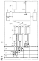
- eine Hardware-Architektur eines Messmoduls,
- Figur 2
- eine erste Konfiguration zum Einsatz der Messmodule und
- Figur 3
- eine zweite Konfiguration zum Einsatz der Messmo- dule.
-
Figur 1 veranschaulicht die wesentlichen Hardwarekomponenten eines Messmoduls 21 als autonom funktionsfähiges Kernelement eines Weichendiagnosesystems. Die drei Adern 1, 2 und 3 zur Bestromung eines Weichenantriebs 23 (Fig. 2/3 ) sind jeweils mit einer Strommesseinrichtung 4 mit Hallsensor 5 und Stromwandler 6 beschaltet. Außerdem ist jede Ader 1, 2 und 3 mit einer Spannungsmesseinrichtung 7 verbunden, wobei die Spannung relativ zu einem Nullleiter 8 gemessen wird und über einen Potential trennenden Wandler 9 ausgegeben wird. Ein Strommesskanal 10 und ein Spannungsmesskanal 11 jeder Ader 1, 2 und 3 ist jeweils über eine Messkanalanpassung 12 bzw. 13 mit einem A/D-Wandler 14 eines Controllers 15 verbunden. Der Controller 15 ermittelt aus den Spannungs- und Stromwerten die Wirkleistung und vergleicht diese mit in einem Speicher 16 abgelegten Sollwerten. Der Controller 15 ist außerdem mit Bedienelementen 17 und Anzeigeelementen 18 verbunden. Über eine Buskopplung 19 können die Diagnoseergebnisse an einer Schnittstelle 20 des Messmoduls 21 abgegriffen werden. -
Figur 2 zeigt Messmodule 21 in einer ersten Konfiguration zum autonomen Betrieb. Dazu ist in die Antriebsverkabelung 22 eines Weichenantriebes 23 das Messmodul 21 eingeschleift, wobei für alle Messmodule 21 eine gemeinsame Stromversorgungseinrichtung 24 vorgesehen ist. Das Messmodul 21 erfasst elektrische Parameter, die von einem stellwerkseitig angesteuerten Stellteil 25 vorgegeben werden und von dem Weichenantrieb 23 entsprechend seines Funktionszustandes weiterverarbeitet werden. - In einer zweiten Konfiguration, die in
Figur 3 veranschaulicht ist, werden zusätzlich die peripheren Schnittstellen 20 der Messmodule 21 zum Anschluss eines Datensammelrechners 26 genutzt. Der Datensammelrechner 26 beinhaltet verschiedene Funktionalitäten, die insbesondere zur automatischen Auswertung der Diagnoseergebnisse dienen. Dazu ist der Datensammelrechner 26 mit einem Massenspeicher 27 zur Datenverwaltung und -archivierung ausgestattet. Zum Anschluss an übergeordnete Einrichtungen der Leit- und Serviceebene können verschiedene Schnittstellen, beispielsweise ISDN 28, Funk 29 oder Ethernet 30 vorgesehen sein. Optional kann der Datensammelrechner 26 mit einem Monitor 31 zur Visualisierung der ausgewerteten Zusammenhänge ausgestattet sein.
Claims (1)
- Weichendiagnosesystem mit einer Messwerterfassungseinrichtung, die mit einer Antriebsverkabelung der Weichen verbunden ist und zur Erfassung elektrischer Messgrößen ausgebildet ist, wobei in die Antriebsverkabelung jeder Weiche ein Messmodul (21) eingeschleift ist, welches Mittel zur Messwerterfassung, -auswertung und -anzeige sowie Schnittstellenmittel (20) zum Anschluss peripherer Geräte, insbesondere Datensammelrechner (26), Fernsteuereinrichtung und Softwareupdateeinrichtung, aufweist,
dadurch gekennzeichnet, dass
das Messmodul (21) in jeder Ader (1, 2, 3) der Antriebsverkabelung eine Strommesseinrichtung (4) mit einem Hallsensor (5), zwischen jeder Ader (1, 2, 3) und einem Nullleiter (8) eine Spannungsmesseinrichtung (7) mit einem Potential trennenden Wandler (9), einem A/D-Wandler (14) vorgeschaltete Messkanalanpassungen (12, 13) für jeden Strommesskanal (10) und jeden Spannungsmesskanal (11) jeder Ader (1, 2, 3), einen den A/D-Wandler (14) und einen Speicher (16) umfassenden Controller (15), die Schnittstellenmittel (20) sowie Anzeige- und Bedienelemente (17, 18) aufweist.
Priority Applications (2)
| Application Number | Priority Date | Filing Date | Title |
|---|---|---|---|
| PL09171617T PL2181907T3 (pl) | 2008-10-29 | 2009-09-29 | System diagnostyczny zwrotnic |
| SI200930267T SI2181907T1 (sl) | 2008-10-29 | 2009-09-29 | Diagnostični sistem za kretnice |
Applications Claiming Priority (1)
| Application Number | Priority Date | Filing Date | Title |
|---|---|---|---|
| DE102008055651A DE102008055651A1 (de) | 2008-10-29 | 2008-10-29 | Weichendiagnosesystem |
Publications (2)
| Publication Number | Publication Date |
|---|---|
| EP2181907A1 EP2181907A1 (de) | 2010-05-05 |
| EP2181907B1 true EP2181907B1 (de) | 2012-04-18 |
Family
ID=41426243
Family Applications (1)
| Application Number | Title | Priority Date | Filing Date |
|---|---|---|---|
| EP09171617A Not-in-force EP2181907B1 (de) | 2008-10-29 | 2009-09-29 | Weichendiagnosesystem |
Country Status (9)
| Country | Link |
|---|---|
| EP (1) | EP2181907B1 (de) |
| AT (1) | ATE553976T1 (de) |
| DE (1) | DE102008055651A1 (de) |
| DK (1) | DK2181907T3 (de) |
| ES (1) | ES2383484T3 (de) |
| HR (1) | HRP20120574T1 (de) |
| PL (1) | PL2181907T3 (de) |
| PT (1) | PT2181907E (de) |
| SI (1) | SI2181907T1 (de) |
Families Citing this family (5)
| Publication number | Priority date | Publication date | Assignee | Title |
|---|---|---|---|---|
| DE102011052449A1 (de) * | 2011-08-05 | 2013-02-07 | Efen Gmbh | Stromwandler sowie Lasttrenner mit einem solchen |
| AU2012396428B2 (en) * | 2012-12-13 | 2017-01-05 | Efen Gmbh | Current transformer and load interrupter having such a current transformer |
| DE102014223234B3 (de) * | 2014-11-14 | 2016-03-17 | Db Netz Ag | Verfahren und Vorrichtung zur Diagnose elektrischer Weichen |
| DE102017217414A1 (de) * | 2017-09-29 | 2019-04-04 | Siemens Mobility GmbH | Verfahren zum Ermitteln einer Stellkraft basierend auf Schallemissionsmessungen |
| DE102018210568A1 (de) | 2018-06-28 | 2020-01-02 | Siemens Aktiengesellschaft | Sensoreinrichtung und Verfahren zur Bestimmung einer Wechselspannung |
Family Cites Families (7)
| Publication number | Priority date | Publication date | Assignee | Title |
|---|---|---|---|---|
| DE3043661A1 (de) * | 1980-11-19 | 1982-07-08 | Siemens AG, 1000 Berlin und 8000 München | Einrichtung bei einem elektronischen stellwerk zum speisen und fernueberwachen von weichenantrieben |
| DE3404825C2 (de) * | 1984-02-09 | 1989-01-12 | Licentia Patent-Verwaltungs-Gmbh, 6000 Frankfurt | Schaltungsanordnung zur Steuerung und Sicherung einer durch eine Fernstelleinrichtung (Stellwerk) oder eine Ortsstelleinrichtung bedienbaren Weiche |
| DE3638681A1 (de) * | 1986-11-13 | 1988-05-19 | Siemens Ag | Einrichtung zum fernueberwachen von drehstromweichenantrieben |
| CN1084478C (zh) | 1995-11-30 | 2002-05-08 | 西门子公司 | 用于检查电气驱动装置的方法和装置 |
| FR2754386B1 (fr) | 1996-10-03 | 1998-10-30 | Commissariat Energie Atomique | Structure comprenant une partie isolee dans un substrat massif et procede de realisation d'une telle structure |
| DE50302423D1 (de) * | 2003-12-08 | 2006-04-20 | Alcatel Sa | Verfahren zur Bestimmung der Wirkleistung eines Drehstrommotors und elektronische Weichensteuerung |
| DE502004000880D1 (de) * | 2004-05-07 | 2006-08-10 | Cit Alcatel | Elektronische Weichensteuerung in einem elektronischen Stellwerk |
-
2008
- 2008-10-29 DE DE102008055651A patent/DE102008055651A1/de not_active Withdrawn
-
2009
- 2009-09-29 ES ES09171617T patent/ES2383484T3/es active Active
- 2009-09-29 SI SI200930267T patent/SI2181907T1/sl unknown
- 2009-09-29 AT AT09171617T patent/ATE553976T1/de active
- 2009-09-29 EP EP09171617A patent/EP2181907B1/de not_active Not-in-force
- 2009-09-29 DK DK09171617.5T patent/DK2181907T3/da active
- 2009-09-29 PT PT09171617T patent/PT2181907E/pt unknown
- 2009-09-29 PL PL09171617T patent/PL2181907T3/pl unknown
-
2012
- 2012-07-10 HR HRP20120574AT patent/HRP20120574T1/hr unknown
Also Published As
| Publication number | Publication date |
|---|---|
| PL2181907T3 (pl) | 2012-09-28 |
| DK2181907T3 (da) | 2012-07-23 |
| EP2181907A1 (de) | 2010-05-05 |
| PT2181907E (pt) | 2012-05-07 |
| SI2181907T1 (sl) | 2012-07-31 |
| DE102008055651A1 (de) | 2010-05-06 |
| ES2383484T3 (es) | 2012-06-21 |
| HRP20120574T1 (hr) | 2012-08-31 |
| ATE553976T1 (de) | 2012-05-15 |
Similar Documents
| Publication | Publication Date | Title |
|---|---|---|
| DE10392421B4 (de) | Handdiagnose- und kommunikationsgerät mit automatischer Buserkennung | |
| EP1638880B1 (de) | Sicherheitssystem einer aufzugsanlage | |
| EP2181907B1 (de) | Weichendiagnosesystem | |
| EP3328771B1 (de) | Verfahren und vorrichtung zum ermitteln eines betriebszustandes einer aufzuganlage | |
| EP2167413B1 (de) | Überwachungsverfahren einer aufzugsanlage | |
| DE4234654A1 (de) | Diagnosesystem für Roboter und Anwendungsverfahren dafür | |
| EP1710647A2 (de) | Integration von Feldgeräten in ein Automatisierungssystem | |
| DE102005047894B4 (de) | Verfahren zur Prüfung der Betriebsfähigkeit von Messumformern | |
| EP0858143A2 (de) | Überwachungseinrichtung für netzbetriebene Haushaltsgeräte | |
| WO2007082773A1 (de) | Drahtlose feldbus verwaltung | |
| EP2963752A2 (de) | Fehlerstromschutzvorrichtung zur ableitstromerfassung | |
| EP1043643B1 (de) | Kabelsystem zur Verkabelung einer Zelle | |
| EP0749628A1 (de) | Einrichtung zur funktionssicherheitsüberwachung von leistungsschalteinrichtungen (diagnosegerät) | |
| EP2437228B1 (de) | Gefahrenmelder, Gefahrenmeldeanlage und Verfahren zum Erkennen von Leitungsfehlern | |
| AT406857B (de) | Einrichtung zum überwachen von gleisfrei-meldeanlagen | |
| EP0327720B1 (de) | Computer-Ein-Ausgabe-Schaltungsanordnung | |
| DE102010037995A1 (de) | Stromversorgungsgerät und Stromversorgungssystem mit ebensolchem | |
| EP3305622A1 (de) | Verfahren zur diagnose von räumlich verteilt angeordneten anlagentechnischen komponenten | |
| EP2684204B1 (de) | Leitungsschaltersystem für ein leitungssystem zur elektrischen versorgung eines fahrzeugs | |
| EP1420495B1 (de) | Installation einer Schutzfunktion in einem Schutzgerät eines elektrischen Energieverteilnetzes | |
| DE102012111018A1 (de) | Mehrkanaliges Messdatenerfassungsgerät | |
| DE102010038459A1 (de) | Sicherheitssystem | |
| EP3686615A1 (de) | Integrierter oder modular aufgebauter kontroller für einen optimierten stromnetzbetrieb eines aus einem wechselspannungs- oder gleichspannungsnetz generierten gleichspannungsnetzes oder hybridnetzes, seine anwendungen sowie ein verfahren für einen optimierten stromnetzbetrieb | |
| EP2362232A2 (de) | Überwachungseinheit für Solarmodule | |
| EP3617114A1 (de) | Verfahren und überwachungsvorrichtung zum überwachen einer sicherheitskettenschaltung in einer aufzuganlage |
Legal Events
| Date | Code | Title | Description |
|---|---|---|---|
| PUAI | Public reference made under article 153(3) epc to a published international application that has entered the european phase |
Free format text: ORIGINAL CODE: 0009012 |
|
| AK | Designated contracting states |
Kind code of ref document: A1 Designated state(s): AT BE BG CH CY CZ DE DK EE ES FI FR GB GR HR HU IE IS IT LI LT LU LV MC MK MT NL NO PL PT RO SE SI SK SM TR |
|
| AX | Request for extension of the european patent |
Extension state: AL BA RS |
|
| 17P | Request for examination filed |
Effective date: 20101102 |
|
| 17Q | First examination report despatched |
Effective date: 20101126 |
|
| GRAP | Despatch of communication of intention to grant a patent |
Free format text: ORIGINAL CODE: EPIDOSNIGR1 |
|
| GRAS | Grant fee paid |
Free format text: ORIGINAL CODE: EPIDOSNIGR3 |
|
| GRAA | (expected) grant |
Free format text: ORIGINAL CODE: 0009210 |
|
| AK | Designated contracting states |
Kind code of ref document: B1 Designated state(s): AT BE BG CH CY CZ DE DK EE ES FI FR GB GR HR HU IE IS IT LI LT LU LV MC MK MT NL NO PL PT RO SE SI SK SM TR |
|
| REG | Reference to a national code |
Ref country code: GB Ref legal event code: FG4D Free format text: NOT ENGLISH |
|
| REG | Reference to a national code |
Ref country code: CH Ref legal event code: NV Representative=s name: SIEMENS SCHWEIZ AG Ref country code: CH Ref legal event code: EP |
|
| REG | Reference to a national code |
Ref country code: PT Ref legal event code: SC4A Free format text: AVAILABILITY OF NATIONAL TRANSLATION Effective date: 20120423 |
|
| REG | Reference to a national code |
Ref country code: IE Ref legal event code: FG4D Free format text: LANGUAGE OF EP DOCUMENT: GERMAN |
|
| REG | Reference to a national code |
Ref country code: AT Ref legal event code: REF Ref document number: 553976 Country of ref document: AT Kind code of ref document: T Effective date: 20120515 |
|
| REG | Reference to a national code |
Ref country code: DE Ref legal event code: R096 Ref document number: 502009003295 Country of ref document: DE Effective date: 20120614 |
|
| REG | Reference to a national code |
Ref country code: ES Ref legal event code: FG2A Ref document number: 2383484 Country of ref document: ES Kind code of ref document: T3 Effective date: 20120621 |
|
| REG | Reference to a national code |
Ref country code: NL Ref legal event code: T3 |
|
| REG | Reference to a national code |
Ref country code: HR Ref legal event code: TUEP Ref document number: P20120574 Country of ref document: HR |
|
| REG | Reference to a national code |
Ref country code: RO Ref legal event code: EPE |
|
| REG | Reference to a national code |
Ref country code: NO Ref legal event code: T2 Effective date: 20120418 |
|
| REG | Reference to a national code |
Ref country code: DK Ref legal event code: T3 |
|
| REG | Reference to a national code |
Ref country code: SE Ref legal event code: TRGR |
|
| REG | Reference to a national code |
Ref country code: EE Ref legal event code: FG4A Ref document number: E006710 Country of ref document: EE Effective date: 20120611 |
|
| REG | Reference to a national code |
Ref country code: HR Ref legal event code: T1PR Ref document number: P20120574 Country of ref document: HR |
|
| REG | Reference to a national code |
Ref country code: GR Ref legal event code: EP Ref document number: 20120401357 Country of ref document: GR Effective date: 20120713 Ref country code: SK Ref legal event code: T3 Ref document number: E 11990 Country of ref document: SK |
|
| REG | Reference to a national code |
Ref country code: PL Ref legal event code: T3 |
|
| PG25 | Lapsed in a contracting state [announced via postgrant information from national office to epo] |
Ref country code: CY Free format text: LAPSE BECAUSE OF FAILURE TO SUBMIT A TRANSLATION OF THE DESCRIPTION OR TO PAY THE FEE WITHIN THE PRESCRIBED TIME-LIMIT Effective date: 20120418 Ref country code: IS Free format text: LAPSE BECAUSE OF FAILURE TO SUBMIT A TRANSLATION OF THE DESCRIPTION OR TO PAY THE FEE WITHIN THE PRESCRIBED TIME-LIMIT Effective date: 20120818 |
|
| REG | Reference to a national code |
Ref country code: HU Ref legal event code: AG4A Ref document number: E014621 Country of ref document: HU |
|
| PLBE | No opposition filed within time limit |
Free format text: ORIGINAL CODE: 0009261 |
|
| STAA | Information on the status of an ep patent application or granted ep patent |
Free format text: STATUS: NO OPPOSITION FILED WITHIN TIME LIMIT |
|
| RAP2 | Party data changed (patent owner data changed or rights of a patent transferred) |
Owner name: SIEMENS AKTIENGESELLSCHAFT |
|
| 26N | No opposition filed |
Effective date: 20130121 |
|
| REG | Reference to a national code |
Ref country code: DE Ref legal event code: R097 Ref document number: 502009003295 Country of ref document: DE Effective date: 20130121 |
|
| REG | Reference to a national code |
Ref country code: HR Ref legal event code: ODRP Ref document number: P20120574 Country of ref document: HR Payment date: 20130826 Year of fee payment: 5 |
|
| PGFP | Annual fee paid to national office [announced via postgrant information from national office to epo] |
Ref country code: MC Payment date: 20130911 Year of fee payment: 5 Ref country code: IE Payment date: 20130927 Year of fee payment: 5 Ref country code: BG Payment date: 20130911 Year of fee payment: 5 Ref country code: CZ Payment date: 20130923 Year of fee payment: 5 Ref country code: LT Payment date: 20130823 Year of fee payment: 5 Ref country code: NL Payment date: 20130902 Year of fee payment: 5 Ref country code: SI Payment date: 20130828 Year of fee payment: 5 Ref country code: NO Payment date: 20130916 Year of fee payment: 5 Ref country code: SE Payment date: 20130909 Year of fee payment: 5 Ref country code: SK Payment date: 20130926 Year of fee payment: 5 Ref country code: FI Payment date: 20130911 Year of fee payment: 5 Ref country code: EE Payment date: 20130911 Year of fee payment: 5 Ref country code: RO Payment date: 20130826 Year of fee payment: 5 Ref country code: DK Payment date: 20130918 Year of fee payment: 5 Ref country code: PT Payment date: 20130401 Year of fee payment: 5 Ref country code: GR Payment date: 20130918 Year of fee payment: 5 |
|
| PG25 | Lapsed in a contracting state [announced via postgrant information from national office to epo] |
Ref country code: MT Free format text: LAPSE BECAUSE OF FAILURE TO SUBMIT A TRANSLATION OF THE DESCRIPTION OR TO PAY THE FEE WITHIN THE PRESCRIBED TIME-LIMIT Effective date: 20120418 |
|
| PGFP | Annual fee paid to national office [announced via postgrant information from national office to epo] |
Ref country code: PL Payment date: 20130826 Year of fee payment: 5 Ref country code: TR Payment date: 20130826 Year of fee payment: 5 Ref country code: GB Payment date: 20130911 Year of fee payment: 5 Ref country code: LV Payment date: 20130910 Year of fee payment: 5 Ref country code: FR Payment date: 20130924 Year of fee payment: 5 Ref country code: HR Payment date: 20130826 Year of fee payment: 5 |
|
| PGFP | Annual fee paid to national office [announced via postgrant information from national office to epo] |
Ref country code: IT Payment date: 20130919 Year of fee payment: 5 |
|
| PGFP | Annual fee paid to national office [announced via postgrant information from national office to epo] |
Ref country code: BE Payment date: 20131010 Year of fee payment: 5 Ref country code: CH Payment date: 20131210 Year of fee payment: 5 Ref country code: LU Payment date: 20131002 Year of fee payment: 5 Ref country code: DE Payment date: 20131120 Year of fee payment: 5 |
|
| PGFP | Annual fee paid to national office [announced via postgrant information from national office to epo] |
Ref country code: HU Payment date: 20131120 Year of fee payment: 5 Ref country code: ES Payment date: 20131004 Year of fee payment: 5 |
|
| PG25 | Lapsed in a contracting state [announced via postgrant information from national office to epo] |
Ref country code: SM Free format text: LAPSE BECAUSE OF FAILURE TO SUBMIT A TRANSLATION OF THE DESCRIPTION OR TO PAY THE FEE WITHIN THE PRESCRIBED TIME-LIMIT Effective date: 20120418 |
|
| REG | Reference to a national code |
Ref country code: DE Ref legal event code: R119 Ref document number: 502009003295 Country of ref document: DE |
|
| REG | Reference to a national code |
Ref country code: HR Ref legal event code: PBON Ref document number: P20120574 Country of ref document: HR Effective date: 20140929 |
|
| REG | Reference to a national code |
Ref country code: PT Ref legal event code: MM4A Free format text: LAPSE DUE TO NON-PAYMENT OF FEES Effective date: 20150330 |
|
| REG | Reference to a national code |
Ref country code: DK Ref legal event code: EBP Effective date: 20140930 |
|
| PG25 | Lapsed in a contracting state [announced via postgrant information from national office to epo] |
Ref country code: PT Free format text: LAPSE BECAUSE OF NON-PAYMENT OF DUE FEES Effective date: 20150330 Ref country code: RO Free format text: LAPSE BECAUSE OF NON-PAYMENT OF DUE FEES Effective date: 20140929 Ref country code: FI Free format text: LAPSE BECAUSE OF NON-PAYMENT OF DUE FEES Effective date: 20140929 Ref country code: CZ Free format text: LAPSE BECAUSE OF NON-PAYMENT OF DUE FEES Effective date: 20140929 Ref country code: LU Free format text: LAPSE BECAUSE OF NON-PAYMENT OF DUE FEES Effective date: 20140929 Ref country code: MC Free format text: LAPSE BECAUSE OF NON-PAYMENT OF DUE FEES Effective date: 20140930 |
|
| REG | Reference to a national code |
Ref country code: CH Ref legal event code: PL |
|
| REG | Reference to a national code |
Ref country code: SE Ref legal event code: EUG |
|
| REG | Reference to a national code |
Ref country code: EE Ref legal event code: MM4A Ref document number: E006710 Country of ref document: EE Effective date: 20140930 |
|
| REG | Reference to a national code |
Ref country code: LT Ref legal event code: MM4D Effective date: 20140929 |
|
| REG | Reference to a national code |
Ref country code: GR Ref legal event code: ML Ref document number: 20120401357 Country of ref document: GR Effective date: 20150403 |
|
| GBPC | Gb: european patent ceased through non-payment of renewal fee |
Effective date: 20140929 |
|
| PG25 | Lapsed in a contracting state [announced via postgrant information from national office to epo] |
Ref country code: SE Free format text: LAPSE BECAUSE OF NON-PAYMENT OF DUE FEES Effective date: 20140930 Ref country code: LV Free format text: LAPSE BECAUSE OF NON-PAYMENT OF DUE FEES Effective date: 20140929 |
|
| REG | Reference to a national code |
Ref country code: SK Ref legal event code: MM4A Ref document number: E 11990 Country of ref document: SK Effective date: 20140929 |
|
| REG | Reference to a national code |
Ref country code: DE Ref legal event code: R119 Ref document number: 502009003295 Country of ref document: DE Effective date: 20150401 |
|
| REG | Reference to a national code |
Ref country code: FR Ref legal event code: ST Effective date: 20150529 |
|
| PG25 | Lapsed in a contracting state [announced via postgrant information from national office to epo] |
Ref country code: NL Free format text: LAPSE BECAUSE OF NON-PAYMENT OF DUE FEES Effective date: 20150401 Ref country code: BE Free format text: LAPSE BECAUSE OF NON-PAYMENT OF DUE FEES Effective date: 20140930 |
|
| REG | Reference to a national code |
Ref country code: SI Ref legal event code: KO00 Effective date: 20150504 |
|
| REG | Reference to a national code |
Ref country code: IE Ref legal event code: MM4A |
|
| PG25 | Lapsed in a contracting state [announced via postgrant information from national office to epo] |
Ref country code: EE Free format text: LAPSE BECAUSE OF NON-PAYMENT OF DUE FEES Effective date: 20140930 Ref country code: LI Free format text: LAPSE BECAUSE OF NON-PAYMENT OF DUE FEES Effective date: 20140930 Ref country code: SI Free format text: LAPSE BECAUSE OF NON-PAYMENT OF DUE FEES Effective date: 20140930 Ref country code: NO Free format text: LAPSE BECAUSE OF NON-PAYMENT OF DUE FEES Effective date: 20140930 Ref country code: CH Free format text: LAPSE BECAUSE OF NON-PAYMENT OF DUE FEES Effective date: 20140930 Ref country code: GB Free format text: LAPSE BECAUSE OF NON-PAYMENT OF DUE FEES Effective date: 20140929 Ref country code: SK Free format text: LAPSE BECAUSE OF NON-PAYMENT OF DUE FEES Effective date: 20140929 Ref country code: DE Free format text: LAPSE BECAUSE OF NON-PAYMENT OF DUE FEES Effective date: 20150401 Ref country code: BG Free format text: LAPSE BECAUSE OF NON-PAYMENT OF DUE FEES Effective date: 20150630 Ref country code: LT Free format text: LAPSE BECAUSE OF NON-PAYMENT OF DUE FEES Effective date: 20140929 Ref country code: HR Free format text: LAPSE BECAUSE OF NON-PAYMENT OF DUE FEES Effective date: 20140929 |
|
| PG25 | Lapsed in a contracting state [announced via postgrant information from national office to epo] |
Ref country code: IE Free format text: LAPSE BECAUSE OF NON-PAYMENT OF DUE FEES Effective date: 20140929 Ref country code: GR Free format text: LAPSE BECAUSE OF NON-PAYMENT OF DUE FEES Effective date: 20150403 Ref country code: IT Free format text: LAPSE BECAUSE OF NON-PAYMENT OF DUE FEES Effective date: 20140929 Ref country code: HU Free format text: LAPSE BECAUSE OF NON-PAYMENT OF DUE FEES Effective date: 20140930 Ref country code: FR Free format text: LAPSE BECAUSE OF NON-PAYMENT OF DUE FEES Effective date: 20140930 |
|
| PG25 | Lapsed in a contracting state [announced via postgrant information from national office to epo] |
Ref country code: DK Free format text: LAPSE BECAUSE OF NON-PAYMENT OF DUE FEES Effective date: 20140930 |
|
| REG | Reference to a national code |
Ref country code: AT Ref legal event code: MM01 Ref document number: 553976 Country of ref document: AT Kind code of ref document: T Effective date: 20140929 |
|
| REG | Reference to a national code |
Ref country code: PL Ref legal event code: LAPE |
|
| REG | Reference to a national code |
Ref country code: ES Ref legal event code: FD2A Effective date: 20160104 |
|
| PG25 | Lapsed in a contracting state [announced via postgrant information from national office to epo] |
Ref country code: AT Free format text: LAPSE BECAUSE OF NON-PAYMENT OF DUE FEES Effective date: 20140929 Ref country code: PL Free format text: LAPSE BECAUSE OF NON-PAYMENT OF DUE FEES Effective date: 20140929 Ref country code: ES Free format text: LAPSE BECAUSE OF NON-PAYMENT OF DUE FEES Effective date: 20140930 |
|
| PG25 | Lapsed in a contracting state [announced via postgrant information from national office to epo] |
Ref country code: TR Free format text: LAPSE BECAUSE OF NON-PAYMENT OF DUE FEES Effective date: 20140929 |
|
| PGFP | Annual fee paid to national office [announced via postgrant information from national office to epo] |
Ref country code: MK Payment date: 20130904 Year of fee payment: 5 |
|
| PG25 | Lapsed in a contracting state [announced via postgrant information from national office to epo] |
Ref country code: MK Free format text: LAPSE BECAUSE OF NON-PAYMENT OF DUE FEES Effective date: 20130930 |