EP2181883A1 - Controller for ac electric train - Google Patents
Controller for ac electric train Download PDFInfo
- Publication number
- EP2181883A1 EP2181883A1 EP07805979A EP07805979A EP2181883A1 EP 2181883 A1 EP2181883 A1 EP 2181883A1 EP 07805979 A EP07805979 A EP 07805979A EP 07805979 A EP07805979 A EP 07805979A EP 2181883 A1 EP2181883 A1 EP 2181883A1
- Authority
- EP
- European Patent Office
- Prior art keywords
- power
- current
- failure
- detection
- signal
- Prior art date
- Legal status (The legal status is an assumption and is not a legal conclusion. Google has not performed a legal analysis and makes no representation as to the accuracy of the status listed.)
- Granted
Links
Images
Classifications
-
- B—PERFORMING OPERATIONS; TRANSPORTING
- B60—VEHICLES IN GENERAL
- B60L—PROPULSION OF ELECTRICALLY-PROPELLED VEHICLES; SUPPLYING ELECTRIC POWER FOR AUXILIARY EQUIPMENT OF ELECTRICALLY-PROPELLED VEHICLES; ELECTRODYNAMIC BRAKE SYSTEMS FOR VEHICLES IN GENERAL; MAGNETIC SUSPENSION OR LEVITATION FOR VEHICLES; MONITORING OPERATING VARIABLES OF ELECTRICALLY-PROPELLED VEHICLES; ELECTRIC SAFETY DEVICES FOR ELECTRICALLY-PROPELLED VEHICLES
- B60L9/00—Electric propulsion with power supply external to the vehicle
- B60L9/16—Electric propulsion with power supply external to the vehicle using AC induction motors
- B60L9/24—Electric propulsion with power supply external to the vehicle using AC induction motors fed from AC supply lines
- B60L9/28—Electric propulsion with power supply external to the vehicle using AC induction motors fed from AC supply lines polyphase motors
-
- B—PERFORMING OPERATIONS; TRANSPORTING
- B60—VEHICLES IN GENERAL
- B60L—PROPULSION OF ELECTRICALLY-PROPELLED VEHICLES; SUPPLYING ELECTRIC POWER FOR AUXILIARY EQUIPMENT OF ELECTRICALLY-PROPELLED VEHICLES; ELECTRODYNAMIC BRAKE SYSTEMS FOR VEHICLES IN GENERAL; MAGNETIC SUSPENSION OR LEVITATION FOR VEHICLES; MONITORING OPERATING VARIABLES OF ELECTRICALLY-PROPELLED VEHICLES; ELECTRIC SAFETY DEVICES FOR ELECTRICALLY-PROPELLED VEHICLES
- B60L3/00—Electric devices on electrically-propelled vehicles for safety purposes; Monitoring operating variables, e.g. speed, deceleration or energy consumption
-
- B—PERFORMING OPERATIONS; TRANSPORTING
- B60—VEHICLES IN GENERAL
- B60L—PROPULSION OF ELECTRICALLY-PROPELLED VEHICLES; SUPPLYING ELECTRIC POWER FOR AUXILIARY EQUIPMENT OF ELECTRICALLY-PROPELLED VEHICLES; ELECTRODYNAMIC BRAKE SYSTEMS FOR VEHICLES IN GENERAL; MAGNETIC SUSPENSION OR LEVITATION FOR VEHICLES; MONITORING OPERATING VARIABLES OF ELECTRICALLY-PROPELLED VEHICLES; ELECTRIC SAFETY DEVICES FOR ELECTRICALLY-PROPELLED VEHICLES
- B60L9/00—Electric propulsion with power supply external to the vehicle
- B60L9/005—Interference suppression
-
- H—ELECTRICITY
- H02—GENERATION; CONVERSION OR DISTRIBUTION OF ELECTRIC POWER
- H02P—CONTROL OR REGULATION OF ELECTRIC MOTORS, ELECTRIC GENERATORS OR DYNAMO-ELECTRIC CONVERTERS; CONTROLLING TRANSFORMERS, REACTORS OR CHOKE COILS
- H02P27/00—Arrangements or methods for the control of AC motors characterised by the kind of supply voltage
- H02P27/04—Arrangements or methods for the control of AC motors characterised by the kind of supply voltage using variable-frequency supply voltage, e.g. inverter or converter supply voltage
- H02P27/06—Arrangements or methods for the control of AC motors characterised by the kind of supply voltage using variable-frequency supply voltage, e.g. inverter or converter supply voltage using DC to AC converters or inverters
-
- B—PERFORMING OPERATIONS; TRANSPORTING
- B60—VEHICLES IN GENERAL
- B60L—PROPULSION OF ELECTRICALLY-PROPELLED VEHICLES; SUPPLYING ELECTRIC POWER FOR AUXILIARY EQUIPMENT OF ELECTRICALLY-PROPELLED VEHICLES; ELECTRODYNAMIC BRAKE SYSTEMS FOR VEHICLES IN GENERAL; MAGNETIC SUSPENSION OR LEVITATION FOR VEHICLES; MONITORING OPERATING VARIABLES OF ELECTRICALLY-PROPELLED VEHICLES; ELECTRIC SAFETY DEVICES FOR ELECTRICALLY-PROPELLED VEHICLES
- B60L2200/00—Type of vehicles
- B60L2200/26—Rail vehicles
Definitions
- the present invention relates to a controller for an AC electric train that is driven by an AC motor, and, more particularly to a controller for an AC electric train having a function of detecting a power failure in an overhead wire (hereinafter, "AC overhead wire”) through which AC electric power is supplied.
- AC overhead wire an overhead wire
- a conventional controller for an AC electric train it is first detected for a current signal of a specific frequency component that is applied from a substation to an AC overhead wiring whether there is a specific frequency component superimposed in the substation using a wave detector on an input side of a main transformer.
- a power failure is detected by a fact that a current signal of the specific frequency component detected by the wave detector could not be detected due to opening of a breaker of a feeding system (see Patent Document 1, for example).
- Patent Document 1 Japanese Patent Application Laid-open No. H6-197401 (Page 3 and Fig. 2 )
- the present invention has been achieved in view of the above problems, and an object of the present invention is to provide a controller for an AC electric train capable of detecting a power failure more swiftly and more reliably than the conventional technique when a power failure is to be detected using a current signal.
- a controller for an AC electric train is constructed in such a manner as to include: a converter that converts an AC voltage input from an AC overhead wire through a transformer, into a DC voltage; an inverter that converts a DC voltage of the converter into an AC voltage and outputs the same to an AC motor; a current detector that detects an output current of the transformer; and a control unit including a converter control device that controls an output of the converter based on a detection current signal detected by the current detector, and a power failure detector that detects a power failure occurring in the AC overhead wire based on the detection current signal, wherein the power failure detector includes: a specific-frequency-signal calculating unit that extracts a current component corresponding to a predetermined specific-frequency set value from the detection current signal and outputs the extracted signal as a specific-frequency current signal; a subtracter that subtracts the detection current signal from the specific-frequency current signal and outputs a result of subtraction as a current deviation;
- a current component corresponding to a predetermined specific-frequency set value is extracted as a specific-frequency current signal from a detection current signal obtained by detecting an output current of a transformer, and a power-failure detection signal is output when a current deviation that is a subtraction result obtained by subtracting the detection current signal from the extracted specific-frequency current signal is greater than a predetermined power-failure-detection set value.
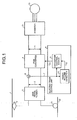
- Fig. 1 depicts a structure of a drive system and a control system of an AC electric train according to an exemplary embodiment of the present invention.
- the drive system of the AC electric train includes a main transformer 3 using AC electric power as an input, a pulse width modulation (PWM) converter 4 using an AC output of the main transformer 3 as an input, an inverter 10 using a DC output of the PWM converter 4 as an input, and one or more motors 13 that are driven by AC output of the inverter 10.
- PWM pulse width modulation
- the motor 13 are an induction motor and a synchronous motor.
- the control system of the AC electric train includes an electric-train control unit 8 that controls the PWM converter 4 based on a current detector 6 and a main-transformer output-current detection signal 7.
- the current detector 6 detects an output current of the main transformer 3.
- the main-transformer output-current detection signal 7 is an output of the current detector 6.
- the electric-train control unit 8 includes a converter control device 9 and a power failure detector 14, and is configured to input the main-transformer output-current detection signal 7 to both of the converter control device 9 and the power failure detector 14.
- one end on a primary side of the main transformer 3 is connected to an AC overhead wire 1 through a pantagraph 2, and the other end thereof is connected to a rail 32 that is a ground potential through a wheel 31. That is, electric power transmitted from a substation (not shown) is received through the AC overhead wire 1, the pantagraph 2, the wheel 31, and the rail 32.
- the operation in the normal conditions is explained first.
- the main transformer 3 When AC electric power collected from the AC overhead wire 1 through the pantagraph 2 is supplied to the main transformer 3, the main transformer 3 outputs a lowered AC voltage to the PWM converter 4 as a main-transformer output voltage 5.
- the PWM converter 4 converts the input main-transformer output voltage 5 into a desired DC voltage, and outputs the converted DC voltage to the inverter 10 as a DC output voltage 11.
- the current detector 6 detects a current flowing between buses that connect the main transformer 3 and the PWM converter 4 with each other, and outputs a detected signal to the converter control device 9 and the power failure detector 14 of the electric-train control unit 8 as the main-transformer output-current detection signal 7.
- the converter control device 9 performs output control on a gate enable signal 12 for keeping the DC output voltage 11 generated by the PWM converter 4 using the main-transformer output voltage 5 at a constant value based on the main-transformer output-current detection signal 7. That is, an output level of the DC output voltage 11 output from the PWM converter 4 to the inverter 10 is controlled by the gate enable signal 12 output from the converter control device 9.
- the inverter 10 converts the input DC output voltage 11 into an AC voltage of a desired frequency and a desired potential, and outputs the same to the motor 13.
- the motor 13 controls running of the electric train using the input AC voltage.
- the electric power is converted as described above to accelerate the motor 13, while at the time of braking (at the time of deceleration), the motor 13 is operated as a power generator.
- the inverter 10 functions as a converter
- the PWM converter 4 functions as an inverter to apply AC-power regenerative braking.
- the controller of the present embodiment can provide control that satisfies both the reliability and the swiftness of the power failure detection.
- a power-failure detection signal 15 is output from the power failure detector 14 to the converter control device 9.
- the power-failure detection signal 15 is generated using the main-transformer output-current detection signal 7 detected by the current detector 6.
- the converter control device 9 completely stops the output of the gate enable signal 12 based on the input power-failure detection signal 15.
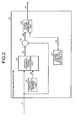
- FIG. 2 depicts a detailed structure of the power failure detector 14 shown in Fig. 1 .
- the power failure detector 14 includes a specific-frequency setting unit 25 that outputs a set value (hereinafter, "specific-frequency set value") 26 representing a specific frequency, a power-failure-detection setting unit 21 that outputs a power-failure-detection set value 22 that is a threshold for determining a power failure based on a current level, a specific-frequency-signal calculating unit 16 using the main-transformer output-current detection signal 7 and the specific-frequency set value 26 as input signals, a subtracter 19 that uses the main-transformer output-current detection signal 7 and a specific-frequency current signal 18 that is an output signal of the specific-frequency-signal calculating unit 16 as input signals, and a power-failure detecting unit 23 using the power-failure-detection set value 22 and a current deviation 20 that is an output signal of the subtracter 19 as input signals.
- An output of the power-failure detecting unit 23 is output as the
- the specific-frequency set value 26 output by the specific-frequency setting unit 25 and the power-failure-detection set value 22 output by the power-failure-detection setting unit 21 can be set at arbitrary values according to a frequency used in a feeding device, electric power to be supplied, the number of vehicles coupled and running together, a type of the coupled vehicles, and the like.
- the specific-frequency-signal calculating unit 16 extracts a current component corresponding to the specific-frequency set value 26 from the main-transformer output-current detection signal 7 that is output from the current detector 6, and outputs the current component to the subtracter 19 as the specific-frequency current signal 18.
- the subtracter 19 subtracts the main-transformer output-current detection signal 7 from the specific-frequency current signal 18, and outputs the subtraction result to the power-failure detecting unit 23 as the current deviation 20.
- the current deviation 20 and the power-failure-detection set value 22 are compared in terms of sizes with each other.
- the current deviation 20 is greater than the power-failure-detection set value 22, it is determined that power fails, and the power-failure detection signal 15 is output to the converter control device 9.
- the current deviation 20 is smaller than the power-failure-detection set value 22, it is determined that power does not fail, and the power-failure detection signal 15 is not output.
- the power failure detector 14 provided in the electric-train control unit 8 swiftly and reliably detects a power failure of the AC overhead wire 1, and if a power failure is detected, the operation of the PWM converter 4 is stopped. Therefore, the regenerative braking operation of the electric train that is supplied with electric power from the AC overhead wire 1 does not function. As a result, AC electric power flowing through the AC overhead wire 1 is lowered, and a power failure on the side of the ground equipment is also detected swiftly and reliably.
- the current signal (main-transformer output-current detection signal 7) flowing at the output of the main transformer 3 is compared with the specific-frequency set value 26, and the output of itself, i.e., the main-transformer output-current detection signal 7 is further subtracted from the comparison output. Therefore, an output difference between a non-power failure case and a power failure case can be increased (the output of the subtracter is small when power does not fail and the output of the subtracter is great when power fails). Therefore, the threshold (power-failure-detection set value 22) for detecting a power failure can be set at a large value, and detection sensitivity and detection precision can be enhanced. As a result, it is possible to suppress an erroneous detection and a detection delay of power failure caused by an operation of the plural vehicles, and it is possible to prevent a failure in the ground equipment such as a substation and to stabilize the vehicle travel.
- the controller for an AC electric train according to the present invention is useful as an invention capable of detecting a power failure swiftly and reliably when a power failure is to be detected using a current signal.
Landscapes
- Engineering & Computer Science (AREA)
- Power Engineering (AREA)
- Life Sciences & Earth Sciences (AREA)
- Sustainable Development (AREA)
- Sustainable Energy (AREA)
- Transportation (AREA)
- Mechanical Engineering (AREA)
- Electric Propulsion And Braking For Vehicles (AREA)
- Protection Of Static Devices (AREA)
Abstract
Description
- The present invention relates to a controller for an AC electric train that is driven by an AC motor, and, more particularly to a controller for an AC electric train having a function of detecting a power failure in an overhead wire (hereinafter, "AC overhead wire") through which AC electric power is supplied.
- According to a conventional controller for an AC electric train, it is first detected for a current signal of a specific frequency component that is applied from a substation to an AC overhead wiring whether there is a specific frequency component superimposed in the substation using a wave detector on an input side of a main transformer. A power failure is detected by a fact that a current signal of the specific frequency component detected by the wave detector could not be detected due to opening of a breaker of a feeding system (see Patent Document 1, for example).
- Patent Document 1: Japanese Patent Application Laid-open No.
H6-197401 Fig. 2 ) - However, in the controller for an AC electric train according to the conventional technique as typified by Patent Document 1 mentioned above, the presence of a detection result of a specific frequency current that flows through the wave detector provided on the input side of the main transformer is used as a determination value for the power failure detection. Therefore, when a plurality of electric trains are connected as loads of the substation, travel of the electric train is delayed due to erroneous detection of the power failure because a current value of the wave detector is high, which hinders smooth travel of the electric train.
- Meanwhile, in this conventional technique, it is possible to change a power-failure-detection set value to lower the probability of the erroneous detection. In this case, however, there is a problem that detection of a power failure at interruption of a feeding circuit is delayed, overcurrent flows through a ground installation such as a substation depending on conditions, which may cause the device to break down.
- The present invention has been achieved in view of the above problems, and an object of the present invention is to provide a controller for an AC electric train capable of detecting a power failure more swiftly and more reliably than the conventional technique when a power failure is to be detected using a current signal.
- In order to solve the aforementioned problems, a controller for an AC electric train according to one aspect of the present invention is constructed in such a manner as to include: a converter that converts an AC voltage input from an AC overhead wire through a transformer, into a DC voltage; an inverter that converts a DC voltage of the converter into an AC voltage and outputs the same to an AC motor; a current detector that detects an output current of the transformer; and a control unit including a converter control device that controls an output of the converter based on a detection current signal detected by the current detector, and a power failure detector that detects a power failure occurring in the AC overhead wire based on the detection current signal, wherein the power failure detector includes: a specific-frequency-signal calculating unit that extracts a current component corresponding to a predetermined specific-frequency set value from the detection current signal and outputs the extracted signal as a specific-frequency current signal; a subtracter that subtracts the detection current signal from the specific-frequency current signal and outputs a result of subtraction as a current deviation; and a power-failure detecting unit that compares the current deviation and a predetermined power-failure-detection set value with each other, and outputs a power-failure detection signal when the current deviation is greater than the power-failure-detection set value.
- According to the controller for an AC electric train of the present invention capable of power running and regenerative running and capable of detecting a power failure in an AC overhead wire through which AC electric power is supplied, a current component corresponding to a predetermined specific-frequency set value is extracted as a specific-frequency current signal from a detection current signal obtained by detecting an output current of a transformer, and a power-failure detection signal is output when a current deviation that is a subtraction result obtained by subtracting the detection current signal from the extracted specific-frequency current signal is greater than a predetermined power-failure-detection set value. Thus, a power failure in the AC overhead wire can be detected swiftly and reliably.
-
- [
Fig. 1] Fig. 1 depicts a structure of a drive system and a control system of an AC electric train according to an exemplary embodiment of the present invention. - [
Fig. 2] Fig. 2 depicts a detailed structure of a power failure detector shown inFig. 1 . -
- 1 AC overhead wire
- 2 pantagraph
- 3 main transformer
- 4 PWM converter
- 5 main-transformer output voltage
- 6 current detector
- 7 main-transformer output-current detection signal
- 8 electric-train control unit
- 9 converter control device
- 10 inverter
- 11 DC output voltage
- 12 gate enable signal
- 13 motor
- 14 power failure detector
- 15 power-failure detection signal
- 16 specific-frequency-signal calculating unit
- 18 specific-frequency current signal
- 19 subtracter
- 20 current deviation
- 21 power-failure-detection setting unit
- 22 power-failure-detection set value
- 23 power-failure detecting unit
- 25 specific-frequency setting unit
- 26 specific-frequency set value
- 31 wheel
- 32 rail
- Exemplary embodiments of a controller for an AC electric train according to the present invention will be explained below in detail with reference to the accompanying drawings. The present invention is not limited to the embodiments.
-
Fig. 1 depicts a structure of a drive system and a control system of an AC electric train according to an exemplary embodiment of the present invention. As shown inFig. 1 , the drive system of the AC electric train includes a main transformer 3 using AC electric power as an input, a pulse width modulation (PWM) converter 4 using an AC output of the main transformer 3 as an input, aninverter 10 using a DC output of the PWM converter 4 as an input, and one ormore motors 13 that are driven by AC output of theinverter 10. Preferable examples of themotor 13 are an induction motor and a synchronous motor. - Meanwhile, the control system of the AC electric train includes an electric-
train control unit 8 that controls the PWM converter 4 based on a current detector 6 and a main-transformer output-current detection signal 7. The current detector 6 detects an output current of the main transformer 3. The main-transformer output-current detection signal 7 is an output of the current detector 6. The electric-train control unit 8 includes a converter control device 9 and apower failure detector 14, and is configured to input the main-transformer output-current detection signal 7 to both of the converter control device 9 and thepower failure detector 14. - Further, one end on a primary side of the main transformer 3 is connected to an AC overhead wire 1 through a pantagraph 2, and the other end thereof is connected to a
rail 32 that is a ground potential through awheel 31. That is, electric power transmitted from a substation (not shown) is received through the AC overhead wire 1, the pantagraph 2, thewheel 31, and therail 32. - An operation of the AC electric train is explained next. In the explanations, the operation of the AC electric train is divided into an operation in normal conditions (when power does not fail) and an operation at detection of a power failure when power fails.
- The operation in the normal conditions (when power does not fail) is explained first. When AC electric power collected from the AC overhead wire 1 through the pantagraph 2 is supplied to the main transformer 3, the main transformer 3 outputs a lowered AC voltage to the PWM converter 4 as a main-
transformer output voltage 5. The PWM converter 4 converts the input main-transformer output voltage 5 into a desired DC voltage, and outputs the converted DC voltage to theinverter 10 as aDC output voltage 11. The current detector 6 detects a current flowing between buses that connect the main transformer 3 and the PWM converter 4 with each other, and outputs a detected signal to the converter control device 9 and thepower failure detector 14 of the electric-train control unit 8 as the main-transformer output-current detection signal 7. The converter control device 9 performs output control on a gate enablesignal 12 for keeping theDC output voltage 11 generated by the PWM converter 4 using the main-transformer output voltage 5 at a constant value based on the main-transformer output-current detection signal 7. That is, an output level of theDC output voltage 11 output from the PWM converter 4 to theinverter 10 is controlled by the gate enablesignal 12 output from the converter control device 9. Theinverter 10 converts the inputDC output voltage 11 into an AC voltage of a desired frequency and a desired potential, and outputs the same to themotor 13. Themotor 13 controls running of the electric train using the input AC voltage. - At the time of power running (at the time of acceleration control) of the electric train, the electric power is converted as described above to accelerate the
motor 13, while at the time of braking (at the time of deceleration), themotor 13 is operated as a power generator. At that time, theinverter 10 functions as a converter, and the PWM converter 4 functions as an inverter to apply AC-power regenerative braking. - An operation at detection of a power failure is explained below. Before that, the reason why a power failure needs to be detected reliably and swiftly is explained. A case in which a breaker of the substation is turned OFF due to an accident of a ground installation or the like is conceived. In this case, some vehicles are applied with AC-power regenerative brakes and some are power running. Therefore, there is a possibility that electric power supplied to the electric train is balanced in terms of electric power, and detection of a power failure on the side of ground equipment is delayed. Thus, when the power fails, it is necessary to swiftly and reliably detect a power failure and to promptly stop the regenerative braking operation not only on the side of the ground equipment but also on the side of the electric train.
- When the reliability (stability) of the power failure detection is sought, the power failure detection is delayed, while when the speed in the power failure detection is increased, this results in precision not being maintained. Although the conventional technique cannot achieve control that satisfies these viewpoints, the controller of the present embodiment can provide control that satisfies both the reliability and the swiftness of the power failure detection.
- Referring back to
Fig. 1 , if a power failure of the AC overhead wire 1 occurs, a power-failure detection signal 15 is output from thepower failure detector 14 to the converter control device 9. The power-failure detection signal 15 is generated using the main-transformer output-current detection signal 7 detected by the current detector 6. The converter control device 9 completely stops the output of the gate enablesignal 12 based on the input power-failure detection signal 15. - A structure of the
power failure detector 14 is explained next.Fig. 2 depicts a detailed structure of thepower failure detector 14 shown inFig. 1 . - In
Fig. 2 , thepower failure detector 14 includes a specific-frequency setting unit 25 that outputs a set value (hereinafter, "specific-frequency set value") 26 representing a specific frequency, a power-failure-detection setting unit 21 that outputs a power-failure-detection set value 22 that is a threshold for determining a power failure based on a current level, a specific-frequency-signal calculating unit 16 using the main-transformer output-current detection signal 7 and the specific-frequency set value 26 as input signals, asubtracter 19 that uses the main-transformer output-current detection signal 7 and a specific-frequencycurrent signal 18 that is an output signal of the specific-frequency-signal calculating unit 16 as input signals, and a power-failure detecting unit 23 using the power-failure-detection set value 22 and acurrent deviation 20 that is an output signal of thesubtracter 19 as input signals. An output of the power-failure detecting unit 23 is output as the power-failure detection signal 15. - The specific-
frequency set value 26 output by the specific-frequency setting unit 25 and the power-failure-detection set value 22 output by the power-failure-detection setting unit 21 can be set at arbitrary values according to a frequency used in a feeding device, electric power to be supplied, the number of vehicles coupled and running together, a type of the coupled vehicles, and the like. - An operation of the
power failure detector 14 is explained next with reference toFigs. 1 and2 . The specific-frequency-signal calculating unit 16 extracts a current component corresponding to the specific-frequency set value 26 from the main-transformer output-current detection signal 7 that is output from the current detector 6, and outputs the current component to thesubtracter 19 as the specific-frequencycurrent signal 18. Thesubtracter 19 subtracts the main-transformer output-current detection signal 7 from the specific-frequencycurrent signal 18, and outputs the subtraction result to the power-failure detecting unit 23 as thecurrent deviation 20. - In the power-
failure detecting unit 23, thecurrent deviation 20 and the power-failure-detection set value 22 are compared in terms of sizes with each other. When thecurrent deviation 20 is greater than the power-failure-detection set value 22, it is determined that power fails, and the power-failure detection signal 15 is output to the converter control device 9. When thecurrent deviation 20 is smaller than the power-failure-detection set value 22, it is determined that power does not fail, and the power-failure detection signal 15 is not output. - As described above, according to the controller for an AC electric train of the present embodiment, the
power failure detector 14 provided in the electric-train control unit 8 swiftly and reliably detects a power failure of the AC overhead wire 1, and if a power failure is detected, the operation of the PWM converter 4 is stopped. Therefore, the regenerative braking operation of the electric train that is supplied with electric power from the AC overhead wire 1 does not function. As a result, AC electric power flowing through the AC overhead wire 1 is lowered, and a power failure on the side of the ground equipment is also detected swiftly and reliably. - In the
power failure detector 14 shown inFig. 2 , the current signal (main-transformer output-current detection signal 7) flowing at the output of the main transformer 3 is compared with the specific-frequency set value 26, and the output of itself, i.e., the main-transformer output-current detection signal 7 is further subtracted from the comparison output. Therefore, an output difference between a non-power failure case and a power failure case can be increased (the output of the subtracter is small when power does not fail and the output of the subtracter is great when power fails). Therefore, the threshold (power-failure-detection set value 22) for detecting a power failure can be set at a large value, and detection sensitivity and detection precision can be enhanced. As a result, it is possible to suppress an erroneous detection and a detection delay of power failure caused by an operation of the plural vehicles, and it is possible to prevent a failure in the ground equipment such as a substation and to stabilize the vehicle travel. - As described above, the controller for an AC electric train according to the present invention is useful as an invention capable of detecting a power failure swiftly and reliably when a power failure is to be detected using a current signal.
Claims (2)
- A controller for an AC electric train, comprising:a converter that converts an AC voltage input from an AC overhead wire through a transformer, into a DC voltage;an inverter that converts a DC voltage of the converter into an AC voltage and outputs the same to an AC motor;a current detector that detects an output current of the transformer; anda control unit including a converter control device that controls an output of the converter based on a detection current signal detected by the current detector, and a power failure detector that detects a power failure occurring in the AC overhead wire based on the detection current signal, whereinthe power failure detector includes:a specific-frequency-signal calculating unit that extracts a current component corresponding to a predetermined specific-frequency set value from the detection current signal and outputs the extracted signal as a specific-frequency current signal;a subtracter that subtracts the detection current signal from the specific-frequency current signal and outputs a result of subtraction as a current deviation; anda power-failure detecting unit that compares the current deviation and a predetermined power-failure-detection set value with each other, and outputs a power-failure detection signal when the current deviation is greater than the power-failure-detection set value.
- The controller for an AC electric train according to claim 1, wherein in the power failure detector, the specific-frequency set value and the power-failure-detection set value are variable.
Applications Claiming Priority (1)
| Application Number | Priority Date | Filing Date | Title |
|---|---|---|---|
| PCT/JP2007/066307 WO2009025049A1 (en) | 2007-08-22 | 2007-08-22 | Controller for ac electric train |
Publications (3)
| Publication Number | Publication Date |
|---|---|
| EP2181883A1 true EP2181883A1 (en) | 2010-05-05 |
| EP2181883A4 EP2181883A4 (en) | 2010-08-04 |
| EP2181883B1 EP2181883B1 (en) | 2012-10-17 |
Family
ID=40377960
Family Applications (1)
| Application Number | Title | Priority Date | Filing Date |
|---|---|---|---|
| EP07805979A Not-in-force EP2181883B1 (en) | 2007-08-22 | 2007-08-22 | Controller for ac electric train |
Country Status (8)
| Country | Link |
|---|---|
| US (1) | US8803356B2 (en) |
| EP (1) | EP2181883B1 (en) |
| JP (1) | JP4243321B1 (en) |
| KR (1) | KR20100009636A (en) |
| CN (1) | CN101687467B (en) |
| CA (1) | CA2692508C (en) |
| ES (1) | ES2396490T3 (en) |
| WO (1) | WO2009025049A1 (en) |
Cited By (2)
| Publication number | Priority date | Publication date | Assignee | Title |
|---|---|---|---|---|
| EP2868515A4 (en) * | 2012-06-29 | 2016-04-13 | Mitsubishi Electric Corp | METHOD FOR CONTROLLING AC ELECTRIC VEHICLE |
| EP2647521A4 (en) * | 2010-12-01 | 2017-05-24 | Mitsubishi Electric Corporation | Control device for electric vehicle |
Families Citing this family (7)
| Publication number | Priority date | Publication date | Assignee | Title |
|---|---|---|---|---|
| US8274804B2 (en) * | 2008-03-04 | 2012-09-25 | Mitsubishi Electric Corporation | Voltage transforming apparatus |
| CN101799521B (en) * | 2010-03-31 | 2011-12-28 | 惠州市德赛西威汽车电子有限公司 | Power supply power-fail method of auto sound singlechip and peripheral circuit equipment |
| KR101260611B1 (en) * | 2011-07-20 | 2013-05-03 | 엘에스산전 주식회사 | Apparatus and method for controlling high voltage inverter |
| CN102529731A (en) * | 2012-01-12 | 2012-07-04 | 赛锐(青岛)自动化技术有限公司 | Electric vehicle driving system and electric vehicle |
| JP2014207735A (en) | 2013-04-10 | 2014-10-30 | ファナック株式会社 | Motor control device capable of taking measures against blackout |
| JP6687423B2 (en) * | 2016-03-01 | 2020-04-22 | 東海旅客鉄道株式会社 | Current collector monitoring device |
| JP6352967B2 (en) * | 2016-03-25 | 2018-07-04 | ファナック株式会社 | Motor control device with power failure detection condition setting function |
Family Cites Families (13)
| Publication number | Priority date | Publication date | Assignee | Title |
|---|---|---|---|---|
| JPS6277062A (en) * | 1985-09-27 | 1987-04-09 | Toshiba Corp | Power interruption detector for power converter |
| JPS62217803A (en) * | 1986-03-19 | 1987-09-25 | Toshiba Corp | Control unit for electric rolling stock |
| JP2548738B2 (en) | 1987-08-28 | 1996-10-30 | 株式会社日立製作所 | PWM converter device |
| JPH01259702A (en) | 1988-04-11 | 1989-10-17 | Toshiba Corp | Controller for ac electrical vehicle |
| JP2672885B2 (en) * | 1990-09-04 | 1997-11-05 | 三菱電機株式会社 | Power failure detection device for AC electric vehicles |
| JP3144848B2 (en) | 1991-09-04 | 2001-03-12 | 東海旅客鉄道株式会社 | Power converter for electric vehicles |
| JP2994892B2 (en) | 1992-11-30 | 1999-12-27 | 東海旅客鉄道株式会社 | Electric vehicle power converter |
| JPH06197401A (en) | 1992-12-24 | 1994-07-15 | Hitachi Ltd | Blackout detection method for electric vehicles |
| JP3314256B2 (en) * | 1994-07-20 | 2002-08-12 | 株式会社日立製作所 | Electric vehicle power converter |
| JPH08182105A (en) * | 1994-12-21 | 1996-07-12 | Toshiba Corp | Electric car control device |
| JPH0956005A (en) * | 1995-08-18 | 1997-02-25 | Hitachi Ltd | Electric car control device |
| EP1885055A4 (en) * | 2005-05-26 | 2011-05-25 | Mitsubishi Electric Corp | ALTERNATING CURRENT MOTOR CONTROL MODULE WITH VARIABLE SPEED |
| KR101066700B1 (en) * | 2006-10-19 | 2011-09-21 | 미쓰비시덴키 가부시키가이샤 | Power converter |
-
2007
- 2007-08-22 ES ES07805979T patent/ES2396490T3/en active Active
- 2007-08-22 JP JP2008520655A patent/JP4243321B1/en active Active
- 2007-08-22 CN CN2007800535226A patent/CN101687467B/en not_active Expired - Fee Related
- 2007-08-22 WO PCT/JP2007/066307 patent/WO2009025049A1/en not_active Ceased
- 2007-08-22 KR KR1020097026244A patent/KR20100009636A/en not_active Ceased
- 2007-08-22 CA CA2692508A patent/CA2692508C/en not_active Expired - Fee Related
- 2007-08-22 US US12/667,709 patent/US8803356B2/en active Active
- 2007-08-22 EP EP07805979A patent/EP2181883B1/en not_active Not-in-force
Cited By (3)
| Publication number | Priority date | Publication date | Assignee | Title |
|---|---|---|---|---|
| EP2647521A4 (en) * | 2010-12-01 | 2017-05-24 | Mitsubishi Electric Corporation | Control device for electric vehicle |
| EP2868515A4 (en) * | 2012-06-29 | 2016-04-13 | Mitsubishi Electric Corp | METHOD FOR CONTROLLING AC ELECTRIC VEHICLE |
| US9845013B2 (en) | 2012-06-29 | 2017-12-19 | Mitsubishi Electric Corporation | Controller of AC electric vehicle |
Also Published As
| Publication number | Publication date |
|---|---|
| CA2692508C (en) | 2014-12-02 |
| ES2396490T3 (en) | 2013-02-21 |
| CN101687467B (en) | 2012-07-18 |
| JP4243321B1 (en) | 2009-03-25 |
| CA2692508A1 (en) | 2009-02-26 |
| WO2009025049A1 (en) | 2009-02-26 |
| EP2181883A4 (en) | 2010-08-04 |
| HK1140457A1 (en) | 2010-10-15 |
| CN101687467A (en) | 2010-03-31 |
| EP2181883B1 (en) | 2012-10-17 |
| KR20100009636A (en) | 2010-01-28 |
| US20100176655A1 (en) | 2010-07-15 |
| JPWO2009025049A1 (en) | 2010-11-18 |
| US8803356B2 (en) | 2014-08-12 |
Similar Documents
| Publication | Publication Date | Title |
|---|---|---|
| US8803356B2 (en) | Controller for AC electric train | |
| EP3159202B1 (en) | Vehicle-use control device | |
| JP5119229B2 (en) | Vehicle control device | |
| CN100550599C (en) | Electric car control device | |
| US9837950B2 (en) | Vehicle control device and railroad vehicle | |
| US9013125B2 (en) | Electric power converter of electric rolling stock | |
| EP2868515B1 (en) | Method for controlling ac electric vehicle | |
| US9716442B2 (en) | Power converter, electric rolling stock and method for controlling sequence test | |
| JPWO2020105080A1 (en) | Power converter and disconnection detection method | |
| JP2014075938A (en) | Electric power converter for electric motor vehicle | |
| JPH06197402A (en) | Controller for ac electric rolling stock | |
| JP4153879B2 (en) | Vehicle drive control device | |
| JP2008228540A (en) | Vehicle drive control device | |
| HK1140457B (en) | Controller for ac electric train | |
| EP2302774A2 (en) | Inverter malfunction stop system | |
| JP2012110075A (en) | Electric vehicle control device | |
| JP2587889B2 (en) | Failure selection device that can determine vehicle failure | |
| JP7059173B2 (en) | Power conversion system | |
| EP3340452B1 (en) | Power conversion device | |
| JPS6311001A (en) | Controller for electric rolling stock |
Legal Events
| Date | Code | Title | Description |
|---|---|---|---|
| PUAI | Public reference made under article 153(3) epc to a published international application that has entered the european phase |
Free format text: ORIGINAL CODE: 0009012 |
|
| 17P | Request for examination filed |
Effective date: 20100105 |
|
| AK | Designated contracting states |
Kind code of ref document: A1 Designated state(s): AT BE BG CH CY CZ DE DK EE ES FI FR GB GR HU IE IS IT LI LT LU LV MC MT NL PL PT RO SE SI SK TR |
|
| AX | Request for extension of the european patent |
Extension state: AL BA HR MK RS |
|
| A4 | Supplementary search report drawn up and despatched |
Effective date: 20100706 |
|
| DAX | Request for extension of the european patent (deleted) | ||
| 17Q | First examination report despatched |
Effective date: 20110314 |
|
| REG | Reference to a national code |
Ref country code: DE Ref legal event code: R079 Ref document number: 602007026176 Country of ref document: DE Free format text: PREVIOUS MAIN CLASS: B60L0009280000 Ipc: B60L0003000000 |
|
| RIC1 | Information provided on ipc code assigned before grant |
Ipc: B60L 3/00 20060101AFI20120112BHEP Ipc: B60L 9/00 20060101ALI20120112BHEP Ipc: B60L 9/28 20060101ALI20120112BHEP Ipc: H02P 27/06 20060101ALI20120112BHEP |
|
| GRAP | Despatch of communication of intention to grant a patent |
Free format text: ORIGINAL CODE: EPIDOSNIGR1 |
|
| GRAS | Grant fee paid |
Free format text: ORIGINAL CODE: EPIDOSNIGR3 |
|
| GRAA | (expected) grant |
Free format text: ORIGINAL CODE: 0009210 |
|
| AK | Designated contracting states |
Kind code of ref document: B1 Designated state(s): AT BE BG CH CY CZ DE DK EE ES FI FR GB GR HU IE IS IT LI LT LU LV MC MT NL PL PT RO SE SI SK TR |
|
| REG | Reference to a national code |
Ref country code: GB Ref legal event code: FG4D |
|
| REG | Reference to a national code |
Ref country code: CH Ref legal event code: EP |
|
| REG | Reference to a national code |
Ref country code: IE Ref legal event code: FG4D |
|
| REG | Reference to a national code |
Ref country code: AT Ref legal event code: REF Ref document number: 579741 Country of ref document: AT Kind code of ref document: T Effective date: 20121115 |
|
| REG | Reference to a national code |
Ref country code: DE Ref legal event code: R096 Ref document number: 602007026176 Country of ref document: DE Effective date: 20121206 |
|
| REG | Reference to a national code |
Ref country code: ES Ref legal event code: FG2A Ref document number: 2396490 Country of ref document: ES Kind code of ref document: T3 Effective date: 20130221 |
|
| REG | Reference to a national code |
Ref country code: AT Ref legal event code: MK05 Ref document number: 579741 Country of ref document: AT Kind code of ref document: T Effective date: 20121017 |
|
| REG | Reference to a national code |
Ref country code: NL Ref legal event code: VDEP Effective date: 20121017 |
|
| REG | Reference to a national code |
Ref country code: LT Ref legal event code: MG4D |
|
| PG25 | Lapsed in a contracting state [announced via postgrant information from national office to epo] |
Ref country code: LT Free format text: LAPSE BECAUSE OF FAILURE TO SUBMIT A TRANSLATION OF THE DESCRIPTION OR TO PAY THE FEE WITHIN THE PRESCRIBED TIME-LIMIT Effective date: 20121017 Ref country code: SE Free format text: LAPSE BECAUSE OF FAILURE TO SUBMIT A TRANSLATION OF THE DESCRIPTION OR TO PAY THE FEE WITHIN THE PRESCRIBED TIME-LIMIT Effective date: 20121017 Ref country code: IS Free format text: LAPSE BECAUSE OF FAILURE TO SUBMIT A TRANSLATION OF THE DESCRIPTION OR TO PAY THE FEE WITHIN THE PRESCRIBED TIME-LIMIT Effective date: 20130217 Ref country code: NL Free format text: LAPSE BECAUSE OF FAILURE TO SUBMIT A TRANSLATION OF THE DESCRIPTION OR TO PAY THE FEE WITHIN THE PRESCRIBED TIME-LIMIT Effective date: 20121017 Ref country code: FI Free format text: LAPSE BECAUSE OF FAILURE TO SUBMIT A TRANSLATION OF THE DESCRIPTION OR TO PAY THE FEE WITHIN THE PRESCRIBED TIME-LIMIT Effective date: 20121017 |
|
| PG25 | Lapsed in a contracting state [announced via postgrant information from national office to epo] |
Ref country code: PT Free format text: LAPSE BECAUSE OF FAILURE TO SUBMIT A TRANSLATION OF THE DESCRIPTION OR TO PAY THE FEE WITHIN THE PRESCRIBED TIME-LIMIT Effective date: 20130218 Ref country code: LV Free format text: LAPSE BECAUSE OF FAILURE TO SUBMIT A TRANSLATION OF THE DESCRIPTION OR TO PAY THE FEE WITHIN THE PRESCRIBED TIME-LIMIT Effective date: 20121017 Ref country code: PL Free format text: LAPSE BECAUSE OF FAILURE TO SUBMIT A TRANSLATION OF THE DESCRIPTION OR TO PAY THE FEE WITHIN THE PRESCRIBED TIME-LIMIT Effective date: 20121017 Ref country code: BE Free format text: LAPSE BECAUSE OF FAILURE TO SUBMIT A TRANSLATION OF THE DESCRIPTION OR TO PAY THE FEE WITHIN THE PRESCRIBED TIME-LIMIT Effective date: 20121017 Ref country code: GR Free format text: LAPSE BECAUSE OF FAILURE TO SUBMIT A TRANSLATION OF THE DESCRIPTION OR TO PAY THE FEE WITHIN THE PRESCRIBED TIME-LIMIT Effective date: 20130118 Ref country code: SI Free format text: LAPSE BECAUSE OF FAILURE TO SUBMIT A TRANSLATION OF THE DESCRIPTION OR TO PAY THE FEE WITHIN THE PRESCRIBED TIME-LIMIT Effective date: 20121017 |
|
| PG25 | Lapsed in a contracting state [announced via postgrant information from national office to epo] |
Ref country code: AT Free format text: LAPSE BECAUSE OF FAILURE TO SUBMIT A TRANSLATION OF THE DESCRIPTION OR TO PAY THE FEE WITHIN THE PRESCRIBED TIME-LIMIT Effective date: 20121017 |
|
| PG25 | Lapsed in a contracting state [announced via postgrant information from national office to epo] |
Ref country code: EE Free format text: LAPSE BECAUSE OF FAILURE TO SUBMIT A TRANSLATION OF THE DESCRIPTION OR TO PAY THE FEE WITHIN THE PRESCRIBED TIME-LIMIT Effective date: 20121017 Ref country code: CZ Free format text: LAPSE BECAUSE OF FAILURE TO SUBMIT A TRANSLATION OF THE DESCRIPTION OR TO PAY THE FEE WITHIN THE PRESCRIBED TIME-LIMIT Effective date: 20121017 Ref country code: DK Free format text: LAPSE BECAUSE OF FAILURE TO SUBMIT A TRANSLATION OF THE DESCRIPTION OR TO PAY THE FEE WITHIN THE PRESCRIBED TIME-LIMIT Effective date: 20121017 Ref country code: SK Free format text: LAPSE BECAUSE OF FAILURE TO SUBMIT A TRANSLATION OF THE DESCRIPTION OR TO PAY THE FEE WITHIN THE PRESCRIBED TIME-LIMIT Effective date: 20121017 Ref country code: BG Free format text: LAPSE BECAUSE OF FAILURE TO SUBMIT A TRANSLATION OF THE DESCRIPTION OR TO PAY THE FEE WITHIN THE PRESCRIBED TIME-LIMIT Effective date: 20130117 |
|
| PLBE | No opposition filed within time limit |
Free format text: ORIGINAL CODE: 0009261 |
|
| STAA | Information on the status of an ep patent application or granted ep patent |
Free format text: STATUS: NO OPPOSITION FILED WITHIN TIME LIMIT |
|
| PG25 | Lapsed in a contracting state [announced via postgrant information from national office to epo] |
Ref country code: IT Free format text: LAPSE BECAUSE OF FAILURE TO SUBMIT A TRANSLATION OF THE DESCRIPTION OR TO PAY THE FEE WITHIN THE PRESCRIBED TIME-LIMIT Effective date: 20121017 Ref country code: RO Free format text: LAPSE BECAUSE OF FAILURE TO SUBMIT A TRANSLATION OF THE DESCRIPTION OR TO PAY THE FEE WITHIN THE PRESCRIBED TIME-LIMIT Effective date: 20121017 |
|
| 26N | No opposition filed |
Effective date: 20130718 |
|
| REG | Reference to a national code |
Ref country code: DE Ref legal event code: R097 Ref document number: 602007026176 Country of ref document: DE Effective date: 20130718 |
|
| PG25 | Lapsed in a contracting state [announced via postgrant information from national office to epo] |
Ref country code: CY Free format text: LAPSE BECAUSE OF FAILURE TO SUBMIT A TRANSLATION OF THE DESCRIPTION OR TO PAY THE FEE WITHIN THE PRESCRIBED TIME-LIMIT Effective date: 20121017 |
|
| REG | Reference to a national code |
Ref country code: CH Ref legal event code: PL |
|
| GBPC | Gb: european patent ceased through non-payment of renewal fee |
Effective date: 20130822 |
|
| PG25 | Lapsed in a contracting state [announced via postgrant information from national office to epo] |
Ref country code: LI Free format text: LAPSE BECAUSE OF NON-PAYMENT OF DUE FEES Effective date: 20130831 Ref country code: CH Free format text: LAPSE BECAUSE OF NON-PAYMENT OF DUE FEES Effective date: 20130831 Ref country code: MC Free format text: LAPSE BECAUSE OF FAILURE TO SUBMIT A TRANSLATION OF THE DESCRIPTION OR TO PAY THE FEE WITHIN THE PRESCRIBED TIME-LIMIT Effective date: 20121017 |
|
| REG | Reference to a national code |
Ref country code: IE Ref legal event code: MM4A |
|
| PG25 | Lapsed in a contracting state [announced via postgrant information from national office to epo] |
Ref country code: GB Free format text: LAPSE BECAUSE OF NON-PAYMENT OF DUE FEES Effective date: 20130822 Ref country code: IE Free format text: LAPSE BECAUSE OF NON-PAYMENT OF DUE FEES Effective date: 20130822 |
|
| PGFP | Annual fee paid to national office [announced via postgrant information from national office to epo] |
Ref country code: DE Payment date: 20140821 Year of fee payment: 8 |
|
| REG | Reference to a national code |
Ref country code: DE Ref legal event code: R084 Ref document number: 602007026176 Country of ref document: DE |
|
| PGFP | Annual fee paid to national office [announced via postgrant information from national office to epo] |
Ref country code: FR Payment date: 20140808 Year of fee payment: 8 Ref country code: ES Payment date: 20140711 Year of fee payment: 8 |
|
| REG | Reference to a national code |
Ref country code: ES Ref legal event code: GC2A Effective date: 20141209 |
|
| REG | Reference to a national code |
Ref country code: DE Ref legal event code: R084 Ref document number: 602007026176 Country of ref document: DE Effective date: 20141107 |
|
| PG25 | Lapsed in a contracting state [announced via postgrant information from national office to epo] |
Ref country code: TR Free format text: LAPSE BECAUSE OF FAILURE TO SUBMIT A TRANSLATION OF THE DESCRIPTION OR TO PAY THE FEE WITHIN THE PRESCRIBED TIME-LIMIT Effective date: 20121017 Ref country code: MT Free format text: LAPSE BECAUSE OF FAILURE TO SUBMIT A TRANSLATION OF THE DESCRIPTION OR TO PAY THE FEE WITHIN THE PRESCRIBED TIME-LIMIT Effective date: 20121017 |
|
| PG25 | Lapsed in a contracting state [announced via postgrant information from national office to epo] |
Ref country code: LU Free format text: LAPSE BECAUSE OF NON-PAYMENT OF DUE FEES Effective date: 20130822 Ref country code: HU Free format text: LAPSE BECAUSE OF FAILURE TO SUBMIT A TRANSLATION OF THE DESCRIPTION OR TO PAY THE FEE WITHIN THE PRESCRIBED TIME-LIMIT; INVALID AB INITIO Effective date: 20070822 |
|
| REG | Reference to a national code |
Ref country code: DE Ref legal event code: R119 Ref document number: 602007026176 Country of ref document: DE |
|
| REG | Reference to a national code |
Ref country code: FR Ref legal event code: ST Effective date: 20160429 |
|
| PG25 | Lapsed in a contracting state [announced via postgrant information from national office to epo] |
Ref country code: DE Free format text: LAPSE BECAUSE OF NON-PAYMENT OF DUE FEES Effective date: 20160301 |
|
| PG25 | Lapsed in a contracting state [announced via postgrant information from national office to epo] |
Ref country code: FR Free format text: LAPSE BECAUSE OF NON-PAYMENT OF DUE FEES Effective date: 20150831 |
|
| REG | Reference to a national code |
Ref country code: ES Ref legal event code: FD2A Effective date: 20161128 |
|
| PG25 | Lapsed in a contracting state [announced via postgrant information from national office to epo] |
Ref country code: ES Free format text: LAPSE BECAUSE OF NON-PAYMENT OF DUE FEES Effective date: 20150823 |